EP1374397B1 - Receiver circuit for mobile radio receivers with automatic amplification control - Google Patents
Receiver circuit for mobile radio receivers with automatic amplification control Download PDFInfo
- Publication number
- EP1374397B1 EP1374397B1 EP01962670A EP01962670A EP1374397B1 EP 1374397 B1 EP1374397 B1 EP 1374397B1 EP 01962670 A EP01962670 A EP 01962670A EP 01962670 A EP01962670 A EP 01962670A EP 1374397 B1 EP1374397 B1 EP 1374397B1
- Authority
- EP
- European Patent Office
- Prior art keywords
- signal
- signal strength
- pgc
- amplifier
- stage
- Prior art date
- Legal status (The legal status is an assumption and is not a legal conclusion. Google has not performed a legal analysis and makes no representation as to the accuracy of the status listed.)
- Expired - Lifetime
Links
Images

Classifications
-
- H—ELECTRICITY
- H03—ELECTRONIC CIRCUITRY
- H03G—CONTROL OF AMPLIFICATION
- H03G3/00—Gain control in amplifiers or frequency changers without distortion of the input signal
- H03G3/20—Automatic control
- H03G3/30—Automatic control in amplifiers having semiconductor devices
- H03G3/3089—Control of digital or coded signals
-
- H—ELECTRICITY
- H03—ELECTRONIC CIRCUITRY
- H03G—CONTROL OF AMPLIFICATION
- H03G3/00—Gain control in amplifiers or frequency changers without distortion of the input signal
- H03G3/001—Digital control of analog signals
-
- H—ELECTRICITY
- H03—ELECTRONIC CIRCUITRY
- H03G—CONTROL OF AMPLIFICATION
- H03G3/00—Gain control in amplifiers or frequency changers without distortion of the input signal
- H03G3/20—Automatic control
- H03G3/30—Automatic control in amplifiers having semiconductor devices
- H03G3/3052—Automatic control in amplifiers having semiconductor devices in bandpass amplifiers (H.F. or I.F.) or in frequency-changers used in a (super)heterodyne receiver
Definitions
- the invention relates to a receiving circuit for a mobile radio receiver, in particular a cordless telephone, which is equipped with a controllable amplifier variable gain. Furthermore, the invention relates to a method for processing a received signal in a mobile radio receiver.
- AGC Automatic Gain Control
- signal strength estimation is in the analog signal processing, i. in the signal path before the analog-to-digital converter stage.
- PGC programmable gain control
- the gain setting is derived from a digital control word output from a signal strength estimator located in the digital signal processing area.
- HSP50214B the company HARRIS Semiconductor (Intersil) is known, which has a PGC and the channel selection in the digital signal processing area (using digital filters).
- the PGC consists of a cascade consisting of 36 individual amplifier stages, each with a gain of 2 dB, which can be individually switched on or off.
- the signal strength estimation takes place in the digital domain on the total signal, ie before the channel selection.
- the disadvantage of this module is mainly the high implementation cost of PGC. Further disadvantages can be seen in the likewise complex realization of the external analog-to-digital converter stage and the digital filter arrangement.
- US Pat. No. 6,005,506 A discloses a receiving circuit for a mobile radio receiver in which a variable gain controllable amplifier, an analogue-to-digital converter stage, a digital filter arrangement for channel selection and a signal strength estimator for determining the signal strength in the selected useful channel are arranged in the signal path ,
- the amplifier is controllable in response to the useful channel signal strength determined by the signal strength estimator.
- the receiving circuit comprises a controllable amplifier 32, an analog-to-digital converter stage 11-1 and 11-2, a digital filter arrangement 12-1 to 12-3 and a signal strength estimator 104.
- An evaluation unit 105 sets the gain of the amplifier 32 on the basis of the estimated value of Signal strength in the selected traffic channel.
- the signal filter arrangement 12-1 to 12-3 consists of band-pass filters for channel selection.
- the invention has for its object to provide a receiving circuit for a mobile radio receiver with a channel selection in the digital signal processing area, which should be ensured that at the input of the analog-to-digital converter stage applied signal does not overdrive the analog-to-digital converter stage. Furthermore, a corresponding method for processing a received signal in a mobile radio receiver is to be specified.
- the signal strength of the broadband input signal drops, while the signal strength of the useful channel signal remains constant, only slightly decreases or even increases. In these cases, an adjustment of the amplifier for the purpose of a level adjustment can be omitted.
- the gain must be readjusted immediately at each drop in the total signal strength, because it must be assumed that the channel-selected useful signal is affected by the loss of energy.
- the circuit has a very good control behavior.
- An advantageous embodiment of the receiving circuit according to the invention is characterized in that the controllable amplifier, in particular PGC, is composed of several amplifier stages, that the receiving circuit comprises an evaluation device which is informed of the signal strength estimator determined useful channel signal strength, and that a Connection of an amplifier stage is always made when the evaluation determines that a predetermined signal-to-noise ratio is exceeded in the received signal.
- This form of level adjustment ensures that the connection of a further amplifier stage of the amplifier is only requested if it is actually required for reasons of too low a signal quality (expressed by the signal-to-noise ratio). This ensures that a minimum number of gain switching points occur over the entire dynamic range. This in turn makes it possible to minimize the number of gain stages of the amplifier. Since the implementation complexity and the cost of the amplifier (eg PGC) is determined by the number of stages, this allows the implementation of a very low-cost hardware for level matching before analog-to-digital conversion.
- this protection against overdriving of the analog-to-digital converter stage is achieved in that the receiving circuit further comprises a memory means in which signal strength values for the useful channel and adjacent channels can be stored, and in that the evaluation device can read out the signal strength values stored in the memory means .
- the receiving circuit further comprises a memory means in which signal strength values for the useful channel and adjacent channels can be stored, and in that the evaluation device can read out the signal strength values stored in the memory means .
- An additional signal strength estimator may be omitted before (in the case of an AGC) or behind (in the case of a PGC) the analog-to-digital converter stage.
- controllable amplifier comprises between three and six, in particular four, amplifier stages.
- a further advantageous embodiment of the invention is characterized in that the analog-to-digital converter stage is implemented by a delta-sigma converter.
- This type of converter is characterized by a reduced implementation cost compared to the commonly used flash digital-to-analog converter.
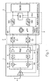
- Fig. 1 shows in the form of a block diagram in an exemplary manner the structure of a receiving circuit according to the invention.
- the receiving circuit can be used in cordless digital communication systems (e.g., DECT, WDCT, Bluetooth, SWAP, WLAN, etc.).
- the receiving circuit has a receiving side arranged circuit part 1, in which an analog signal processing is performed, an output side arranged circuit part 2, in which the signal processing is digital, and an analog-to-digital converter stage 3, which in the signal path between the analog circuit part 1 and the digital circuit part 2 is provided.
- a radio signal is picked up by an antenna A and fed to a low-noise input amplifier LNA.
- the gain of the LNA can be made adjustable so that the LNA simultaneously represents the foremost stage of the PGC as shown in FIG.
- the input amplifier LNA amplifies the high-frequency antenna signal.
- An output of the amplifier LNA is supplied to a high-frequency mixer M.
- the RF mixer M comprises two mixers M1, M2 which downconvert the amplified high frequency signal to an intermediate frequency range.
- the mixers M1 and M2 are operated in a known manner with a phase offset of 90 ° with an adjustable mixing frequency. At their outputs is in each case an analog intermediate frequency signal (in-phase branch or quadrature branch) ready.
- the RF mixer M is followed by a unit E for prefiltering and amplification of the received from the RF mixer M intermediate frequency signals.
- the unit E has on the input side for each signal branch on an analog low-pass filter TP, which is also referred to in the art as an anti-aliasing filter.
- the outputs of the two low-pass filters TP are each supplied to a PGC.
- the gain of both PGCs is variable and can be adjusted via a common control signal input to which a common control signal S is applied. Since the control signal S is a digital control word, the setting of the gain of the PGC is also referred to as programming.
- Each PGC is constructed in a manner not shown from a plurality of series-connected amplifier stages of a constant but not necessarily identical gain. The gain adjustment then takes place by simply switching an amplifier stage on or off in response to an instruction by the control signal word S.
- the outputs of the two PGC simultaneously represent the outputs of the analog circuit part 1.
- the said outputs are each supplied to an analog-to-digital converter 3.1 or 3.2.
- the two analog-to-digital converters 3.1 and 3.2 realize the analog-to-digital converter stage 3.
- a digital intermediate frequency signal is output whose bandwidth is limited only by the low-pass filter TP. This means that the digital intermediate-frequency signals output by the analog-to-digital converter stage 3 can cover several, in particular also all available user channels.
- the outputs of the analog-to-digital converters 3.1 and 3.2 are fed to a complex digital intermediate frequency (IF) mixer dM.
- the digital IF mixer dM multiplies the digital signal values by a phase signal exp (jw 0 t) of the angular frequency w 0 .
- t denotes the time and j the imaginary unit.
- the digital IF mixer dM shifts the frequency position of the received digital signal by the ia fixed frequency w 0 / 2 ⁇ .
- the digital mixer dM has two outputs at which wideband digital receive signals of the I-branch and the Q-branch are output.
- a channel selection and decimation stage KS1 or KS2 is provided in each signal branch.
- the two channel selection and decimation KS1, KS2 are identical and will be described in more detail in connection with FIG.
- a digital signal is output, whose bandwidth is limited to the channel bandwidth and compared to the sampling rate of the analog-to-digital converters 3.1 and 3.2 has lowered signal rate (data symbol rate).
- the tuning of this signal to a desired Traffic channel is carried out by means of the analog, adjustable mixers M1, M2.
- the two outputs of the channel selection and decimation KS1, KS2 are fed into a digital demodulator DMOD, which demodulates the signals according to the standard underlying the signal transmission in a known manner.
- the demodulation may include, for example, adaptive channel estimation, equalization, channel decoding, etc.
- the demodulated signal is subsequently suitably further processed, i. e.g. deinterleaved, source decoded, converted into an analog signal, amplified and fed to a suitable output unit (e.g., speaker, monitor).
- the outputs of the two channel selection and decimation stages KS1, KS2 are also connected to a power estimator PE.
- the power estimator PE makes a power estimation in the traffic channel based on the obtained digital signals of the I and Q branches.
- the result of this power estimation i.e., a digitally coded value indicating the power measured in the payload channel
- PGC programmer PGC-PROG via a data line DL1.
- the PGC programming unit PGC-PROG controls the PGC. In the event that the PGC is made up of several amplifier stages that can be switched on and off, the PGC programming unit PGC-PROG tells the PGC how many amplifier stages are to be activated. If the amplifier stages have different gains, the control signal issued by the PGC programmer PGC-PROG also notifies the PGC, which of the amplifier stages are to be activated or deactivated.
- the switching of the PGC to a greater gain always takes place when a predetermined minimum signal-to-noise ratio in the bandwidth-limited useful channel signal is exceeded.
- a threshold can be defined which ensures that a maximum bit error rate, e.g. at the output of the digital demodulator DMOD is not exceeded.
- the signal-to-noise ratio is calculated in the PGC programming unit PGC-PROG from the power value communicated via the data line DL1 and a noise power.
- the noise power (or noise level) is determined by the input noise of the receiver and the inherent noise of the analog circuit part 1 of the receiver, ie the dimensioning of the analog signal path.
- the noise power depends on the selected gain of the PGC.
- a value for the corresponding noise power is stored in the PGC programming unit PGC-PROG.
- the signal-to-noise ratio occurring in the useful channel is then determined by quotienting the power value output by the power estimator PE with the noise power value stored in the PGC programming unit PGC-PROG with respect to the selected programming calculated. Another possibility is to determine the noise power in the user channel by direct measurement.
- FIGS. 3a and 3b the logarithmic signal-to-noise ratio SNR (in dB) is plotted against the logarithmic ratio of the level of the input signal before the PGC to the maximum allowable signal level of that input signal (in dBm).
- the minimum permissible signal-to-noise ratio is 20 dB in this example.
- the connection of an amplifier stage takes place whenever the signal-to-noise ratio becomes less than 20 dB, i. at the switching points P1, P2, P3.
- a PGC comprising four amplifier stages is sufficient.
- Fig. 3b the level of the signal in the useful channel behind the channel selection and decimation KS1 or KS2 (curve K1), the level of the (broadband) total signal behind the PGC (curve K2) and the (gain-dependent) noise level (curve K3) in the useful channel compared to the level of the input signal before the PGC (in dBm in each case) (the two diagrams of FIGS. 3a and 3b have a common x-axis). It becomes clear that with each connection of an amplifier stage, a sudden increase in the useful signal level (curve K1) occurs. The opposite applies to the deactivation of an amplifier stage with increasing level of the input signal.
- the curve K3 makes it clear that the noise level in the useful channel does not necessarily have to reduce when an amplifier stage is switched off. Since an amplifier stage also amplifies the noise of the signal paths in front of it lying function blocks, is indeed when switching off an amplifier stage basically to expect a reduction of the total noise. At point P3, however, this effect is not significant since there (in the particular example illustrated) the gain in the foremost amplifier stage is changed. At point P2, a noise reduction is detected as a middle amplifier stage is taken out. The gain adjustment at point P1 is done (in the concrete example) by a change in the gain of a switch capacitor realization that forms the rearmost amplifier stage. This amplifier stage has a much larger inherent noise with a small amplifier setting, so that the resulting total noise in the reception path increases (even).
- the magnitude of the switched gain (when the input signal level drops) must be selected so that the overall broadband signal behind the PGC does not lead to overmodulation of the analog-to-digital converters 3.1 or 3.2. Since the overall signal behind the PGC is composed of the useful signal and possible (possibly larger) signals in adjacent channels, it is for a reliable prevention of overdriving at the input of the analog-to-digital converter 3.1. or 3.2 is not sufficient to evaluate only the power in the payload signal (according to the information output by the power estimator PE).
- One way to prevent overdriving the analog-to-digital converter 3.1, 3.2 is to remove the signal power of adjacent channels of a channel list. To explain this possibility, reference is made to FIGS. 2 and 4.
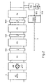
- FIG. 2 shows the detail A of the receiving circuit shown in FIG. 1, which is bordered by a dashed line.
- the digital circuit part 2 has a memory SP whose input is connected to the output of the power estimator PE. An exit of the memory SP is connected to the PGC programming unit PGC-PROG via a data line DL2.
- a so-called RSSI scan is performed at regular intervals, in which the signal strength (or power) is determined in all available channels and registered in a list, which is managed by the memory SP.
- An example of such a channel list is shown in FIG. The example is based on an FDMA / TDMA multiple access system with ten available frequency bands (channels) and twelve time slots. In the example shown, a useful signal in the frequency band 5 is now to be received within the time slot 5.
- the signal strength values of all available channels which were determined by the power estimator PE in the RSSI scan, are entered in the unit dBm. Channels with signal strengths less than e.g. -96 dBm are marked as free channels in the list. Channels 1 to 4, 6, 9 and 10 are therefore free. Channels in which larger signals are measured (channels 5, 7, 8) are marked as occupied.
- the channel list is only used to find out which channels are free and thus available for a possible handover.
- the information contained in the channel list is also used to exclude an override of the input of the analog-to-digital converter stage 3.
- the PGC programming unit PGC-PROG reads out the signal strength values entered in the channel list for the time slot 5 and determines the largest signal value. in the present case -30 dBm in the channel 8.
- the gain of the PGC is then set via the control signal S so that even taking into account the largest interference signal (channel 8) no Override at the input of the analog-to-digital converter stage 3 occurs.
- that amplifier stage can be selected and switched on, which has the maximum gain among those amplifier stages that would cause a clipping no overdriving of the analog-to-digital converter 3.1 and 3.2, respectively.
- Shutdown of a transmitter stage may also be performed based on the signal strength values stored in the channel list whenever a signal level value appears in the list indicating that the analog to digital converter stage is overdriven, i. which takes a maximum value. If an additional signal level estimator is provided at the input (for an AGC) or at the output (for a PGC) of the analog-to-digital converter stage 3, of course, this can also be used to initiate a shutdown of an amplifier stage.
- the analog-to-digital converter stage 3 is shown in more detail in connection with the low-pass filters TP of FIG.
- the analog-to-digital conversion is performed by a delta-sigma modulator MOD of order L and the channel filtering by a cascade consisting of three decimation stages DZ1, DZ2, DZ3 and four filter stages F1, F2, F3, F4.
- the filter stages F1, F2, F3, F4 and the decimation stages DZ1, DZ2, DZ3 are arranged alternately, so that from filter stage to filter stage in each case a sampling rate reduction takes place for example by a factor of 2.
- the filter stage F1 arranged on the input side in the signal path can be realized by a so-called sinc k filter of the L + 1th order.
- the two subsequent filter stages F2 and F3 are realized by minimal-phase bridge wave or wave digital filters.
- the second filter stage F2 may be a bifilar wave digital filter and the third filter stage F3 may be a bridge wave digital filter.
- the output-side filter stage F4 can be realized in the form of a simple attenuation filter (equalizer filter). This filter F4 serves to compensate for group delay distortions caused by the upstream recursive filters.
- the minimum-phase bridge wave or wave digital filters F2 and F3 are characterized in that they have a minimum group delay.
- the implementation cost of these filters F2 and F3 is significantly lower than that of FIR filter.
- the illustrated filter concept thus has clear advantages over a filter cascade using FIR filters.
- Fig. 2 delta-sigma modulator MOD, F1, DZ1, F2, DZ2, F3, DZ3, F4 beyond a reduced implementation effort in the field of analog signal processing (ie in the delta-sigma modulator MOD).
- a data control line running from the PGC programmer PGC-PROG to the low-noise input amplifier is designated DL3 in FIG.
Abstract
Description
Die Erfindung betrifft eine Empfangsschaltung für einen Mobilfunkempfänger, insbesondere ein schnurloses Telefon, die mit einem steuerbaren Verstärker variabler Verstärkung ausgerüstet ist. Ferner betrifft die Erfindung ein Verfahren zum Verarbeiten eines empfangenen Signals in einem Mobilfunkempfänger.The invention relates to a receiving circuit for a mobile radio receiver, in particular a cordless telephone, which is equipped with a controllable amplifier variable gain. Furthermore, the invention relates to a method for processing a received signal in a mobile radio receiver.
Durch die Weiterentwicklung der mobilen Kommunikationssysteme, u.a. hinsichtlich eines flexibleren Dienstangebots, werden neue Anforderungen an die zukünftigen Endgeräte und an deren Systemkomponenten gestellt. Insbesondere wird eine höhere Flexibilität, geringerer Leistungsverbrauch, kleinere Abmessungen und geringere Kosten gefordert.Through the further development of mobile communication systems, i.a. With regard to a more flexible service offering, new requirements are placed on the future terminals and their system components. In particular, higher flexibility, lower power consumption, smaller dimensions and lower costs are required.
Eine Möglichkeit, diesen Anforderungen gerecht zu werden, besteht darin, die analoge Signalverarbeitung, die in heutigen Mobilfunkempfängern überwiegend zum Einsatz kommt, weitestgehend durch digitale Signalverarbeitung zu ersetzen. So ist es durch die Leistungssteigerung der Digitaltechnik in den letzten Jahren möglich geworden, auch höherfrequente Zwischenfrequenzsignale digital weiter zu verarbeiten, wodurch der Anteil der Analogfunktionen im Hochfrequenzteil des Empfängers deutlich reduziert werden kann. Generell führt die zunehmende Verlagerung von Signalverarbeitungsaufgaben in den Digitalbereich zu einer besseren Integrierbarkeit und Flexibilität des Systemkonzepts, einer Verbesserung der Langzeitstabilität sowie zu einer reduzierten Anzahl von Abgleichpunkten bei der Optimierung des Empfängers.One way to meet these requirements is to largely replace the analog signal processing used in today's mobile radio receivers with digital signal processing. It has become possible through the increase in performance of digital technology in recent years, even digitally process higher frequency intermediate frequency signals, whereby the proportion of analog functions in the high frequency part of the receiver can be significantly reduced. In general, the increasing shift of signal processing tasks into the digital domain leads to better integratability and flexibility of the system concept, an improvement of the long-term stability as well as to a reduced number of adjustment points in the optimization of the receiver.
In diesem Zusammenhang ist es bereits bekannt, auf eine Kanalselektion im Analogbereich zu verzichten, stattdessen das breitbandige Zwischenfrequenzsignal zu digitalisieren und die Kanalselektion mittels digitaler Filter im Digitalbereich vorzunehmen.In this context, it is already known to dispense with a channel selection in the analog domain, instead digitizing the wideband intermediate frequency signal and the Channel selection using digital filters in the digital domain.
Den bereits genannten Systemvorteilen einer solchen Lösung stehen jedoch auch Nachteile gegenüber. Bei der Umsetzung eines breitbandigen und hochfrequenten Zwischenfrequenzsignals in den Digitalbereich ist ein erheblicher Zusatzaufwand für den Analog-Digital-Umsetzer erforderlich. Dieser muß bei der Digitalisierung des breitbandigen Zwischenfrequenzsignals hohen Dynamik- und Bandbreitanforderungen gerecht werden.However, the already mentioned system advantages of such a solution are also faced with disadvantages. In the implementation of a broadband and high-frequency intermediate frequency signal in the digital domain, a significant overhead for the analog-to-digital converter is required. This must meet high dynamic and bandwidth requirements in the digitization of the broadband intermediate frequency signal.
Um den hohen Bandbreiteanforderungen gerecht zu werden, ist es bereits bekannt, Analog-Digital-Wandler einzusetzen, die nach dem Flash-Verfahren arbeiten. Nachteilig ist, daß dieser Wandlertyp sehr aufwendig und teuer ist.In order to meet the high bandwidth requirements, it is already known to use analog-to-digital converters which operate according to the flash method. The disadvantage is that this type of converter is very complicated and expensive.
Zur Reduzierung der Dynamikanforderungen an den Analog-Digital-Umsetzer (es können Dynamikunterschiede bis zu 100 dB im Empfangssignal auftreten) ist es bereits bekannt, eine automatische Verstärkungssteuerung AGC (Automatic Gain Control) im Analogteil zu realisieren. Die AGC bewirkt, daß das Eingangssignal des Analog-Digital-Umsetzers stets auf einen optimalen Pegel eingestellt wird. Nachteilig ist, daß auch die AGC einen erheblichen Implementierungsaufwand erfordert.To reduce the dynamic demands on the analog-to-digital converter (dynamic differences of up to 100 dB can occur in the received signal), it is already known to realize an automatic gain control AGC (Automatic Gain Control) in the analog part. The AGC causes the input signal of the analog-to-digital converter is always set to an optimal level. The disadvantage is that the AGC requires a considerable implementation effort.
Bei einer AGC erfolgt die Signalstärkenschätzung im Bereich der analogen Signalverarbeitung, d.h. im Signalweg vor der Analog-Digital-Umsetzerstufe. Eine bekannte Modifikation einer AGC ist die PGC (programmable gain control). Bei einer PGC wird die Verstärkungseinstellung aus einem digitalen Steuerwort abgeleitet, welches von einem Signalstärkenschätzer ausgegeben wird, welcher im digitalen Signalverarbeitungsbereich angeordnet ist.In an AGC, signal strength estimation is in the analog signal processing, i. in the signal path before the analog-to-digital converter stage. One known modification of an AGC is the PGC (programmable gain control). In a PGC, the gain setting is derived from a digital control word output from a signal strength estimator located in the digital signal processing area.
Es ist ein Mobilfunk-Umsetzerbaustein der Bezeichnung HSP50214B der Firma HARRIS Semiconductor (Intersil) bekannt, der eine PGC aufweist und die Kanalselektion im digitalen Signalverarbeitungsbereich (mittels digitaler Filter) vornimmt. Die PGC ist aus einer Kaskade bestehend aus 36 Einzelverstärkerstufen jeweils einer Verstärkung von 2 dB aufgebaut, die einzeln zu- bzw. abschaltbar sind. Die Signalstärkenschätzung erfolgt im digitalen Bereich am Gesamtsignal, d.h. vor der Kanalselektion.It is a mobile converter module called HSP50214B the company HARRIS Semiconductor (Intersil) is known, which has a PGC and the channel selection in the digital signal processing area (using digital filters). The PGC consists of a cascade consisting of 36 individual amplifier stages, each with a gain of 2 dB, which can be individually switched on or off. The signal strength estimation takes place in the digital domain on the total signal, ie before the channel selection.
Nachteilig bei diesem Baustein ist vor allem der hohe Realisierungsaufwand der PGC. Weitere Nachteile sind in der ebenfalls aufwendigen Realisierung der externen Änalog-Digital-Umsetzerstufe und der Digitalfilteranordnung zu sehen.The disadvantage of this module is mainly the high implementation cost of PGC. Further disadvantages can be seen in the likewise complex realization of the external analog-to-digital converter stage and the digital filter arrangement.
In der Druckschrift US 6,005,506 A ist eine Empfangsschaltung für einen Mobilfunkempfänger offenbart, bei welcher im Signalweg ein steuerbarer Verstärker mit variabler Verstärkung, eine Analog-Digital-Umsetzerstufe, eine Digital-Filteranordnung zur Kanalselektion und ein Signalstärkenschätzer zur Ermittlung der Signalstärke im selektierten Nutzkanal angeordnet sind. Der Verstärker ist in Abhängigkeit von der von dem Signalstärkenschätzer ermittelten Nutzkanal-Signalstärke steuerbar.US Pat. No. 6,005,506 A discloses a receiving circuit for a mobile radio receiver in which a variable gain controllable amplifier, an analogue-to-digital converter stage, a digital filter arrangement for channel selection and a signal strength estimator for determining the signal strength in the selected useful channel are arranged in the signal path , The amplifier is controllable in response to the useful channel signal strength determined by the signal strength estimator.
In der Druckschrift JP 11-261433 ist ebenfalls eine Empfangsschaltung für einen Mobilfunkempfänger offenbart. Die Empfangsschaltung umfasst einen steuerbaren Verstärker 32, eine Analog-Digital-Umsetzerstufe 11-1 und 11-2, eine DigitalFilteranordnung 12-1 bis 12-3 sowie einen Signalstärkenschätzer 104. Eine Auswerteeinrichtung 105 stellt die Verstärkung des Verstärkers 32 anhand des geschätzten Werts der Signalstärke im selektierten Nutzkanal ein. Die Signalfilteranordnung 12-1 bis 12-3 besteht aus Bandpaßfiltern zur Kanalselektion.In the publication JP 11-261433 a receiving circuit for a mobile radio receiver is also disclosed. The receiving circuit comprises a controllable amplifier 32, an analog-to-digital converter stage 11-1 and 11-2, a digital filter arrangement 12-1 to 12-3 and a signal strength estimator 104. An evaluation unit 105 sets the gain of the amplifier 32 on the basis of the estimated value of Signal strength in the selected traffic channel. The signal filter arrangement 12-1 to 12-3 consists of band-pass filters for channel selection.
Der Erfindung liegt die Aufgabe zugrunde, eine Empfangsschaltung für einen Mobilfunkempfänger mit einer Kanalselektion im digitalen Signalverarbeitungsbereich anzugeben, wobei gewährleistet sein soll, daß das am Eingang der Analog-Digital-Umsetzerstufe anliegende Signal die Analog-Digital-Umsetzerstufe nicht übersteuert. Ferner soll ein entsprechendes Verfahren zum Verarbeiten eines empfangenen Signals in einem Mobilfunkempfänger angegeben werden.The invention has for its object to provide a receiving circuit for a mobile radio receiver with a channel selection in the digital signal processing area, which should be ensured that at the input of the analog-to-digital converter stage applied signal does not overdrive the analog-to-digital converter stage. Furthermore, a corresponding method for processing a received signal in a mobile radio receiver is to be specified.
Die der Erfindung zugrunde liegende Aufgabe wird durch die Merkmale der unabhängigen Ansprüche gelöst.The object underlying the invention is solved by the features of the independent claims.
Dadurch, daß für die Einstellung einer geeigneten Verstärkung des steuerbaren Verstärkers eine Information zur Verfügung steht, die die Signalstärke im Nutzkanal betrifft, kann eine gezieltere, d.h. besser an die tatsächlichen Erfordernisse angepaßte Verstärkungs-Nachstellung im Verstärker vorgenommen werden.Characterized in that for the setting of a suitable gain of the controllable amplifier information is available, which relates to the signal strength in the traffic channel, a more targeted, i. better adapted to the actual requirements amplification adjustment in the amplifier are made.
Beispielsweise kann es vorkommen, daß die Signalstärke des breitbandigen Eingangssignals sinkt, während die Signalstärke des Nutzkanal-Signals konstant bleibt, nur unwesentlich abnimmt oder sich sogar erhöht. In diesen Fällen kann eine Nachstellung des Verstärkers zum Zwecke einer Pegelanpassung unterbleiben. Wenn andererseits eine die Signalstärke im Nutzkanal betreffende Information nicht verfügbar ist, muß bei jedem Abfallen der Gesamtsignalstärke die Verstärkung sofort nachgeregelt werden, weil davon ausgegangen werden muß, daß auch das kanalselektierte Nutzsignal von dem Energieverlust betroffen ist.For example, it may happen that the signal strength of the broadband input signal drops, while the signal strength of the useful channel signal remains constant, only slightly decreases or even increases. In these cases, an adjustment of the amplifier for the purpose of a level adjustment can be omitted. On the other hand, if a signal strength in the useful channel information is not available, the gain must be readjusted immediately at each drop in the total signal strength, because it must be assumed that the channel-selected useful signal is affected by the loss of energy.
Im Ergebnis wird durch die Erfindung eine aufwandsgünstige Realisierung des Verstärkers ermöglicht, wobei die Schaltung ein sehr gutes Regelverhalten aufweist.As a result, a low-cost implementation of the amplifier is made possible by the invention, the circuit has a very good control behavior.
Eine vorteilhafte Ausführungsform der erfindungsgemäßen Empfangsschaltung kennzeichnet sich dadurch, daß der steuerbare Verstärker, insbesondere PGC, aus mehreren Verstärkerstufen aufgebaut ist, daß die Empfangsschaltung eine Auswerteeinrichtung umfaßt, der die von dem Signalstärkenschätzer ermittelte Nutzkanal-Signalstärke mitgeteilt wird, und daß eine Zuschaltung einer Verstärkerstufe immer dann vorgenommen wird, wenn die Auswerteeinrichtung feststellt, daß ein vorgegebenes Signal-zu-Rauschverhältnis im Empfangssignal unterschritten wird. Durch diese Form der Pegelanpassung wird erreicht, daß die Zuschaltung einer weiteren Verstärkerstufe des Verstärkers nur dann angefordert wird, wenn sie aus Gründen einer zu geringen Signalqualität (ausgedrückt durch das Signal-zu-Rauschverhältnis) auch tatsächlich benötigt wird. Dadurch wird erreicht, daß eine minimale Anzahl von Verstärkungs-Umschaltpunkten über den gesamten Dynamikbereich auftreten. Dies wiederum ermöglicht es, die Anzahl der Verstärkungsstufen des Verstärkers zu minimieren. Da der Realisierungsaufwand und die Kosten des Verstärkers (z.B. PGC) von der Anzahl seiner Stufen bestimmt wird, ermöglicht dies die Implementierung einer ausgesprochen kostengünstigen Hardware für die Pegelanpassung vor der Analog-Digital-Umsetzung.An advantageous embodiment of the receiving circuit according to the invention is characterized in that the controllable amplifier, in particular PGC, is composed of several amplifier stages, that the receiving circuit comprises an evaluation device which is informed of the signal strength estimator determined useful channel signal strength, and that a Connection of an amplifier stage is always made when the evaluation determines that a predetermined signal-to-noise ratio is exceeded in the received signal. This form of level adjustment ensures that the connection of a further amplifier stage of the amplifier is only requested if it is actually required for reasons of too low a signal quality (expressed by the signal-to-noise ratio). This ensures that a minimum number of gain switching points occur over the entire dynamic range. This in turn makes it possible to minimize the number of gain stages of the amplifier. Since the implementation complexity and the cost of the amplifier (eg PGC) is determined by the number of stages, this allows the implementation of a very low-cost hardware for level matching before analog-to-digital conversion.
Ferner ist dafür zu sorgen, daß das am Eingang der Analog-Digital-Umsetzerstufe anliegende breitbandige Signal die Analog-Digital-Umsetzerstufe nicht übersteuert. Zu diesem Zweck ist es erforderlich, die am Eingang des Analog-Digital-Umsetzers auftretende Signalstärke zu bewerten. Gemäß der Erfindung wird dieser Schutz vor einer Übersteuerung der Analog-Digital-Umsetzerstufe dadurch erreicht, daß die Empfangsschaltung ferner ein Speichermittel aufweist, in welchem Signalstärkenwerte für den Nutzkanal und für Nachbarkanäle abspeicherbar sind, und daß die Auswerteeinrichtung die in dem Speichermittel abgelegten Signalstärkenwerte auslesen kann. Der Vorteil dieser Maßnahme besteht darin, daß ein derartiges Speichermittel sowie die in diesem Speichermittel abgespeicherten Informationen (z.B. Leistungs- oder Signalpegelwerte des Nutzkanals und der Nachbarkanäle) bei den meisten digitalen Mobilfunkempfängern (z.B. bei GSM-, DECT- und Bluetooth-Empfängern) aus anderen Gründen, die später erläutert werden, bereits vorhanden sind. Dadurch, daß die Auswerteeinrichtung Zugriff auf die in dem Speichermittel abgelegten Signalstärkenwerte hat, und diese Werte in geeigneter Weise für die Steuerung des Verstärkers berücksichtigen kann, kann ein zusätzlicher Signalstärkenschätzer vor (im Falle eines AGCs) oder hinter (im Falle eines PGCs) der Analog-Digital-Umsetzerstufe entfallen.Furthermore, it must be ensured that the broadband signal present at the input of the analog-digital converter stage does not overdrive the analog-to-digital converter stage. For this purpose, it is necessary to evaluate the signal strength occurring at the input of the analog-to-digital converter. According to the invention, this protection against overdriving of the analog-to-digital converter stage is achieved in that the receiving circuit further comprises a memory means in which signal strength values for the useful channel and adjacent channels can be stored, and in that the evaluation device can read out the signal strength values stored in the memory means , The advantage of this measure is that such a storage means and the information stored in this memory means (eg power or signal level values of the user channel and the adjacent channels) in most digital mobile radio receivers (eg in GSM, DECT and Bluetooth receivers) from others Reasons that will be explained later, already exist. Characterized in that the evaluation device has access to the signal strength values stored in the memory means, and these values in a suitable An additional signal strength estimator may be omitted before (in the case of an AGC) or behind (in the case of a PGC) the analog-to-digital converter stage.
Vorzugsweise umfaßt der steuerbare Verstärker zwischen drei und sechs, insbesondere vier, Verstärkerstufen.Preferably, the controllable amplifier comprises between three and six, in particular four, amplifier stages.
Eine weitere vorteilhafte Ausgestaltung der Erfindung kennzeichnet sich dadurch, daß die Analog-Digital-Umsetzerstufe durch einen Delta-Sigma-Umsetzer realisiert ist. Dieser Wandlertyp zeichnet sich durch einen reduzierten Realisierungsaufwand im Vergleich zu dem üblicherweise verwendeten Flash-Digital-Analog-Umsetzer aus.A further advantageous embodiment of the invention is characterized in that the analog-to-digital converter stage is implemented by a delta-sigma converter. This type of converter is characterized by a reduced implementation cost compared to the commonly used flash digital-to-analog converter.
Weitere vorteilhafte Ausgestaltungen der Erfindung sind in den Unteransprüchen angegeben.Further advantageous embodiments of the invention are specified in the subclaims.
Die Erfindung wird nachfolgend anhand eines Ausführungsbeispiels unter Bezugnahme auf die Zeichnung erläutert; in dieser zeigt:
- Fig. 1
- eine schematische Schaltbilddarstellung einer erfindungsgemäßen Empfangsschaltung;
- Fig. 2
- eine schematische Schaltbilddarstellung des Ausschnitts A aus Fig. 1 in größerem Detail;
- Fig. 3a
- ein Schaubild, in welchem das Signal-zu-Rauschverhältnis im Nutzkanal über dem Pegel des Eingangssignals für die PGC aufgetragen ist;
- Fig. 3b
- ein Schaubild, in welchem die Pegel des Gesamtsignals, des Nutzsignals und des Rauschsignals im Nutzkanal hinter der PGC über dem Pegel des Eingangssignals für die PGC aufgetragen sind; und
- Fig. 4
- eine Tabelle, in welcher Signalpegelwerte für die verfügbaren Frequenzbänder bezüglich eines bestimmten Zeitschlitzes angegeben sind.
- Fig. 1
- a schematic diagram of a receiving circuit according to the invention;
- Fig. 2
- a schematic diagram representation of the section A of Figure 1 in more detail.
- Fig. 3a
- a graph in which the signal-to-noise ratio in the traffic channel is plotted against the level of the input signal for the PGC;
- Fig. 3b
- a graph in which the levels of the total signal, the desired signal and the noise signal in the useful channel behind the PGC are plotted against the level of the input signal for the PGC; and
- Fig. 4
- a table in which signal level values for the available frequency bands are given with respect to a specific time slot.
Fig. 1 zeigt in Form eines Blockschaltbilds in beispielhafter Weise den Aufbau einer erfindungsgemäßen Empfangsschaltung. Die Empfangsschaltung kann in schnurlosen digitalen Kommunikationssystemen (z.B. DECT, WDCT, Bluetooth, SWAP, WLAN usw.) eingesetzt werden.Fig. 1 shows in the form of a block diagram in an exemplary manner the structure of a receiving circuit according to the invention. The receiving circuit can be used in cordless digital communication systems (e.g., DECT, WDCT, Bluetooth, SWAP, WLAN, etc.).
Die Empfangsschaltung weist ein empfangsseitig angeordnetes Schaltungsteil 1, in welchem eine analoge Signalverarbeitung durchgeführt wird, ein ausgangsseitig angeordnetes Schaltungsteil 2, in welchem die Signalverarbeitung digital erfolgt, und eine Analog-Digital-Umsetzerstufe 3 auf, welche im Signalweg zwischen dem analogen Schaltungsteil 1 und dem digitalen Schaltungsteil 2 vorgesehen ist.The receiving circuit has a receiving side arranged
Ein Funksignal wird von einer Antenne A aufgefangen und einem rauscharmen Eingangsverstärker LNA zugeführt. Die Verstärkung des LNA kann einstellbar ausgeführt sein, so daß der LNA gleichzeitig, wie in Fig. 1 dargestellt, die vorderste Stufe der PGC darstellt. Der Eingangsverstärker LNA verstärkt das hochfrequente Antennensignal. Ein Ausgangssignal des Verstärkers LNA wird einer Hochfrequenz-Mischstufe M zugeführt. Die HF-Mischstufe M umfaßt zwei Mischer M1, M2, welche das verstärkte Hochfrequenzsignal in einen Zwischenfrequenzbereich heruntermischen. Die Mischer M1 und M2 werden in bekannter Weise unter einem Phasenversatz von 90° mit einer einstellbaren Mischfrequenz betrieben. An ihren Ausgängen steht jeweils ein analoges Zwischenfrequenzsignal (Inphase-Zweig bzw. Quadratur-Zweig) bereit.A radio signal is picked up by an antenna A and fed to a low-noise input amplifier LNA. The gain of the LNA can be made adjustable so that the LNA simultaneously represents the foremost stage of the PGC as shown in FIG. The input amplifier LNA amplifies the high-frequency antenna signal. An output of the amplifier LNA is supplied to a high-frequency mixer M. The RF mixer M comprises two mixers M1, M2 which downconvert the amplified high frequency signal to an intermediate frequency range. The mixers M1 and M2 are operated in a known manner with a phase offset of 90 ° with an adjustable mixing frequency. At their outputs is in each case an analog intermediate frequency signal (in-phase branch or quadrature branch) ready.
Der HF-Mischstufe M ist eine Einheit E zur Vorfilterung und Verstärkung der von der HF-Mischstufe M empfangenen Zwischenfrequenzsignale nachgeschaltet. Die Einheit E weist eingangsseitig für jeden Signalzweig ein analoges Tiefpaßfilter TP auf, das in der Technik auch als Anti-Aliasing-Filter bezeichnet wird.The RF mixer M is followed by a unit E for prefiltering and amplification of the received from the RF mixer M intermediate frequency signals. The unit E has on the input side for each signal branch on an analog low-pass filter TP, which is also referred to in the art as an anti-aliasing filter.
Die Ausgänge der beiden Tiefpaßfilter TP werden jeweils einer PGC zugeführt. Die Verstärkung beider PGCs ist variabel und kann über einen gemeinsamen Steuersignaleingang, dem ein gemeinsames Steuersignal S zugeführt wird, eingestellt werden. Da es sich bei dem Steuersignal S um ein digitales Steuerwort handelt, wird die Einstellung der Verstärkung der PGC auch als Programmierung bezeichnet.The outputs of the two low-pass filters TP are each supplied to a PGC. The gain of both PGCs is variable and can be adjusted via a common control signal input to which a common control signal S is applied. Since the control signal S is a digital control word, the setting of the gain of the PGC is also referred to as programming.
Jede PGC ist in nicht dargestellter Weise aus mehreren hintereinander geschalteten Verstärkerstufen einer konstanten aber nicht notwendigerweise identischen Verstärkung aufgebaut. Die Verstärkungseinstellung erfolgt dann durch einfaches Zu- bzw. Abschalten einer Verstärkerstufe in Abhängigkeit von einer Anweisung durch das Steuersignalwort S.Each PGC is constructed in a manner not shown from a plurality of series-connected amplifier stages of a constant but not necessarily identical gain. The gain adjustment then takes place by simply switching an amplifier stage on or off in response to an instruction by the control signal word S.
Die Ausgänge der beiden PGC stellen gleichzeitig die Ausgänge des analogen Schaltungsteils 1 dar.The outputs of the two PGC simultaneously represent the outputs of the
Die genannten Ausgänge werden jeweils einem Analog-Digital-Umsetzer 3.1 bzw. 3.2 zugeführt. Die beiden Analog-Digital-Umsetzer 3.1 und 3.2 realisieren die Analog-Digital-Umsetzerstufe 3. An den Ausgängen der Analog-Digital-Umsetzer 3.1, 3.2 wird ein digitales Zwischenfrequenzsignal ausgegeben, dessen Bandbreite allein durch das Tiefpaßfilter TP eingeschränkt ist. D.h., daß die von der Analog-Digital-Umsetzerstufe 3 ausgegebenen digitalen Zwischenfrequenzsignale mehrere, insbesondere auch sämtliche verfügbaren Benutzerkanäle überdecken können.The said outputs are each supplied to an analog-to-digital converter 3.1 or 3.2. The two analog-to-digital converters 3.1 and 3.2 realize the analog-to-
Die Ausgänge der Analog-Digital-Umsetzer 3.1 bzw. 3.2 werden einem komplexen, digitalen Zwischenfrequenz-(ZF-)Mischer dM zugeführt. Der digitale ZF-Mischer dM multipliziert die digitalen Signalwerte mit einem Phasensignal exp(jw0t) der Kreisfrequenz w0. In diesem Ausdruck bezeichnet t die Zeit und j die imaginäre Einheit. Der digitale ZF-Mischer dM verschiebt die Frequenzlage des empfangenen digitalen Signals um die i.a. feste Frequenz w0/2π.The outputs of the analog-to-digital converters 3.1 and 3.2 are fed to a complex digital intermediate frequency (IF) mixer dM. The digital IF mixer dM multiplies the digital signal values by a phase signal exp (jw 0 t) of the angular frequency w 0 . In this expression t denotes the time and j the imaginary unit. The digital IF mixer dM shifts the frequency position of the received digital signal by the ia fixed frequency w 0 / 2π.
Der digitale Mischer dM weist zwei Ausgänge auf, an denen breitbandige, digitale Empfangssignale des I-Zweigs und des Q-Zweigs ausgegeben werden.The digital mixer dM has two outputs at which wideband digital receive signals of the I-branch and the Q-branch are output.
Im Signalweg hinter dem digitalen Mischer dM ist in jedem Signalzweig eine Kanalselektions- und Dezimationsstufe KS1 bzw. KS2 vorgesehen. Die beiden Kanalselektions- und Dezimationsstufen KS1, KS2 sind baugleich und werden in Zusammenhang mit Fig. 2 noch näher beschrieben. Am Ausgang jeder der beiden Stufen KS1 bzw. KS2 wird ein digitales Signal ausgegeben, dessen Bandbreite auf die Kanalbandbreite begrenzt ist und eine gegenüber der Abtastrate der Analog-Digital-Umsetzer 3.1 bzw. 3.2 erniedrigte Signalrate (Datensymbolrate) aufweist. Die Abstimmung dieses Signals auf einen gewünschten Nutzkanal erfolgt mittels der analogen, einstellbaren Mischer M1, M2.In the signal path behind the digital mixer dM, a channel selection and decimation stage KS1 or KS2 is provided in each signal branch. The two channel selection and decimation KS1, KS2 are identical and will be described in more detail in connection with FIG. At the output of each of the two stages KS1 and KS2, a digital signal is output, whose bandwidth is limited to the channel bandwidth and compared to the sampling rate of the analog-to-digital converters 3.1 and 3.2 has lowered signal rate (data symbol rate). The tuning of this signal to a desired Traffic channel is carried out by means of the analog, adjustable mixers M1, M2.
Die beiden Ausgänge der Kanalselektions- und Dezimationsstufen KS1, KS2 werden in einen digitalen Demodulator DMOD eingespeist, welcher die Signale entsprechend dem der Signalübertragung zugrundeliegenden Standard in bekannter Weise demoduliert. Die Demodulation kann beispielsweise eine adaptive Kanalschätzung, eine Entzerrung, eine Kanaldecodierung usw. umfassen. In nicht dargestellter Weise wird das demodulierte Signal nachfolgend geeignet weiter verarbeitet, d.h. z.B. entschachtelt, quellendecodiert, in ein analoges Signal umgesetzt, verstärkt und einer geeigneten Ausgabeeinheit (z.B. Lautsprecher, Monitor) zugeführt.The two outputs of the channel selection and decimation KS1, KS2 are fed into a digital demodulator DMOD, which demodulates the signals according to the standard underlying the signal transmission in a known manner. The demodulation may include, for example, adaptive channel estimation, equalization, channel decoding, etc. In a manner not shown, the demodulated signal is subsequently suitably further processed, i. e.g. deinterleaved, source decoded, converted into an analog signal, amplified and fed to a suitable output unit (e.g., speaker, monitor).
Die Ausgänge der beiden Kanalselektions- und Dezimationsstufen KS1, KS2 stehen ferner mit einem Leistungsschätzer PE in Verbindung. Der Leistungsschätzer PE nimmt auf der Basis der erhaltenen digitalen Signale des I- und des Q-Zweigs eine Leistungsschätzung in dem Nutzkanal vor. Das Ergebnis dieser Leistungsschätzung (d.h. ein digital codierter Wert, der die im Nutzkanal gemessene Leistung bezeichnet) wird einer PGC-Programmiereinheit PGC-PROG über eine Datenleitung DL1 mitgeteilt.The outputs of the two channel selection and decimation stages KS1, KS2 are also connected to a power estimator PE. The power estimator PE makes a power estimation in the traffic channel based on the obtained digital signals of the I and Q branches. The result of this power estimation (i.e., a digitally coded value indicating the power measured in the payload channel) is communicated to a PGC programmer PGC-PROG via a data line DL1.
Anstelle der Leistungsschätzung kann auch eine andere Form der Signalstärkenbewertung, z.B. die Ermittlung einer Empfangsfeldstärke, eines Signal-Spannungspegels usw. vorgenommen werden.Instead of the power estimate, another form of signal strength evaluation, e.g. the determination of a reception field strength, a signal voltage level, etc. are made.
Die PGC-Programmiereinheit PGC-PROG steuert die PGC. Für den Fall, daß die PGC aus mehreren zu- bzw. abschaltbaren Verstärkerstufen aufgebaut ist, teilt die PGC-Programmiereinheit PGC-PROG dem PGC mit, wie viele Verstärkerstufen aktiviert werden sollen. Sofern die Verstärkerstufen unterschiedliche Verstärkungen haben, teilt das von der PGC-Programmiereinheit PGC-PROG ausgegebene Steuersignal der PGC auch mit, welche der Verstärkerstufen zu aktivieren bzw. zu deaktivieren sind.The PGC programming unit PGC-PROG controls the PGC. In the event that the PGC is made up of several amplifier stages that can be switched on and off, the PGC programming unit PGC-PROG tells the PGC how many amplifier stages are to be activated. If the amplifier stages have different gains, the control signal issued by the PGC programmer PGC-PROG also notifies the PGC, which of the amplifier stages are to be activated or deactivated.
Die Umschaltung der PGC auf eine größere Verstärkung (Zuschaltung einer Verstärkerstufe) erfolgt immer dann, wenn ein vorgegebenes minimales Signal-zu-Rauschverhältnis im bandbreitenbegrenzten Nutzkanalsignal unterschritten wird. Als minimales Signal-zu-Rauschverhältnis kann ein Schwellenwert definiert werden, welcher gewährleistet, daß eine maximale Bitfehlerrate z.B. am Ausgang des digitalen Demodulators DMOD nicht überschritten wird. Durch die Steuerung der Schaltpunkte der PGC in Abhängigkeit von der im Nutzkanal gemessenen Leistung, der im Nutzkanal auftretenden Rauschleistung und dem vorgegebenen Schwellenwert wird erreicht, daß eine Umschaltung der PGC nur dann vorgenommen wird, wenn diese - unter dem Gesichtspunkt einer nicht mehr akzeptablen Bitfehlerrate - zwingend erforderlich ist. Im Ergebnis wird dadurch erreicht, daß nur eine minimale Anzahl von Umschaltpunkten über den gesamten Leistungsbereich auftritt. Dies ermöglicht auf der anderen Seite, eine PGC mit einer geringstmöglichen Anzahl von Verstärkerstufen einzusetzen.The switching of the PGC to a greater gain (connection of an amplifier stage) always takes place when a predetermined minimum signal-to-noise ratio in the bandwidth-limited useful channel signal is exceeded. As the minimum signal-to-noise ratio, a threshold can be defined which ensures that a maximum bit error rate, e.g. at the output of the digital demodulator DMOD is not exceeded. By controlling the switching points of the PGC as a function of the power measured in the useful channel, the noise power occurring in the useful channel and the predetermined threshold is achieved that a changeover of the PGC is made only if this - from the viewpoint of an unacceptable bit error rate - is mandatory. As a result, it is achieved that only a minimum number of switching points over the entire power range occurs. On the other hand, this makes it possible to use a PGC with a minimum number of amplifier stages.
Das Signal-zu-Rauschverhältnis wird in der PGC-Programmiereinheit PGC-PROG aus dem über die Datenleitung DL1 mitgeteilten Leistungswert und einer Rauschleistung berechnet. Die Rauschleistung (bzw. der Rauschpegel) ist durch das Eingangsrauschen des Empfängers und das Eigenrauschen des analogen Schaltungsteils 1 des Empfängers, d.h. der Dimensionierung des analogen Signalpfads, bestimmt. Die Rauschleistung ist dabei abhängig von der gewählten Verstärkung der PGC. Zu jeder möglichen Programmierung der PGC ist in der PGC-Programmiereinheit PGC-PROG ein Wert für die entsprechende Rauschleistung abgespeichert. Das in dem Nutzkanal auftretende Signal-zu-Rauschverhältnis wird dann durch Quotientenbildung des von dem Leistungsschätzer PE ausgegebenen Leistungswerts mit dem in der PGC-Programmiereinheit PGC-PROG bezüglich der gewählten Programmierung abgespeicherten Rauschleistungswert berechnet. Eine andere Möglichkeit besteht darin, die Rauschleistung im Nutzkanal durch direkte Messung zu bestimmen.The signal-to-noise ratio is calculated in the PGC programming unit PGC-PROG from the power value communicated via the data line DL1 and a noise power. The noise power (or noise level) is determined by the input noise of the receiver and the inherent noise of the
Zur Erläuterung der erfindungsgemäßen Zu- bzw. Abschaltung von Verstärkerstufen wird auf die Figuren 3a und 3b Bezug genommen. In Fig. 3a ist das logarithmische Signal-zu-Rauschverhältnis SNR (in dB) über dem logarithmischen Verhältnis des Pegels des Eingangssignals vor der PGC zu dem maximal zulässigen Signalpegel dieses Eingangssignals (in dBm) aufgetragen. Das minimal zulässige Signal-zu-Rauschverhältnis beträgt in diesem Beispiel 20 dB. Ausgehend von einer maximalen Signalstärke (Aussteuerungsgrenze) bei 0 dBm am Eingang der PGC erfolgt die Zuschaltung einer Verstärkerstufe immer dann, wenn das Signal-zu-Rauschverhältnis kleiner als 20 dB wird, d.h. an den Umschaltpunkten P1, P2, P3. Zur Durchführung des erläuterten Verfahrens ist eine vier Verstärkerstufen umfassende PGC ausreichend.To explain the connection or disconnection of amplifier stages according to the invention, reference is made to FIGS. 3a and 3b. In Fig. 3a, the logarithmic signal-to-noise ratio SNR (in dB) is plotted against the logarithmic ratio of the level of the input signal before the PGC to the maximum allowable signal level of that input signal (in dBm). The minimum permissible signal-to-noise ratio is 20 dB in this example. Starting from a maximum signal strength (modulation limit) at 0 dBm at the input of the PGC, the connection of an amplifier stage takes place whenever the signal-to-noise ratio becomes less than 20 dB, i. at the switching points P1, P2, P3. To carry out the described method, a PGC comprising four amplifier stages is sufficient.
In Fig. 3b sind der Pegel des Signals im Nutzkanal hinter der Kanalselektions- und Dezimationsstufe KS1 bzw. KS2 (Kurve K1), der Pegel des (breitbandigen) Gesamtsignals hinter der PGC (Kurve K2) sowie der (verstärkungsabhängige) Rauschpegel (Kurve K3) im Nutzkanal gegenüber dem Pegel des Eingangssignals vor der PGC (jeweils in dBm) dargestellt (die beiden Schaubilder der Fig. 3a und 3b weisen eine gemeinsame x-Achse auf). Es wird deutlich, daß bei jeder Zuschaltung einer Verstärkerstufe eine sprunghafte Erhöhung des Nutzsignalpegels (Kurve K1) auftritt. Gegenteiliges gilt bei der Deaktivierung einer Verstärkerstufe bei steigendem Pegel des Eingangssignals.In Fig. 3b, the level of the signal in the useful channel behind the channel selection and decimation KS1 or KS2 (curve K1), the level of the (broadband) total signal behind the PGC (curve K2) and the (gain-dependent) noise level (curve K3) in the useful channel compared to the level of the input signal before the PGC (in dBm in each case) (the two diagrams of FIGS. 3a and 3b have a common x-axis). It becomes clear that with each connection of an amplifier stage, a sudden increase in the useful signal level (curve K1) occurs. The opposite applies to the deactivation of an amplifier stage with increasing level of the input signal.
Die Kurve K3 macht deutlich, daß sich der Rauschpegel im Nutzkanal nicht notwendigerweise bei Abschaltung einer Verstärkerstufe reduzieren muß. Da eine Verstärkerstufe das Rauschen der im Signalpfad vor ihr liegenden Funktionsblöcke mitverstärkt, ist bei Abschalten einer Verstärkerstufe zwar grundsätzlich mit einer Verminderung des Gesamtrauschens zu rechnen. Beim Punkt P3 ist dieser Effekt aber nicht signifikant, da dort (in dem speziellen, dargestellten Beispiel) die Verstärkung in der vordersten Verstärkerstufe geändert wird. Am Punkt P2 ist eine Rauschreduzierung festzustellen, da eine mittlere Verstärkerstufe herausgenommen wird. Die Verstärkereinstellung am Punkt P1 erfolgt (im konkreten Beispiel) durch eine Änderung der Verstärkung einer Schalter-Kondensatorrealisierung, die die hinterste Verstärkerstufe bildet. Diese Verstärkerstufe weist bei kleiner Verstärkereinstellung ein deutlich größeres Eigenrauschen auf, so daß sich das resultierende Gesamtrauschen im Empfangspfad (sogar) erhöht.The curve K3 makes it clear that the noise level in the useful channel does not necessarily have to reduce when an amplifier stage is switched off. Since an amplifier stage also amplifies the noise of the signal paths in front of it lying function blocks, is indeed when switching off an amplifier stage basically to expect a reduction of the total noise. At point P3, however, this effect is not significant since there (in the particular example illustrated) the gain in the foremost amplifier stage is changed. At point P2, a noise reduction is detected as a middle amplifier stage is taken out. The gain adjustment at point P1 is done (in the concrete example) by a change in the gain of a switch capacitor realization that forms the rearmost amplifier stage. This amplifier stage has a much larger inherent noise with a small amplifier setting, so that the resulting total noise in the reception path increases (even).
Bei der Umschaltung der PGC muß beachtet werden, daß die Grö-ße der zugeschalteten Verstärkung (bei abfallendem Eingangssignalpegel) so gewählt sein muß, daß das breitbandige Gesamtsignal hinter der PGC zu keiner Übersteuerung der Analog-Digital-Umsetzer 3.1 bzw. 3.2 führt. Da sich das Gesamtsignal hinter der PGC aus dem Nutzsignal und möglichen (ggf. größeren) Signalen in Nachbarkanälen zusammensetzt, ist es für eine sichere Vermeidung von Übersteuerungen am Eingang der Analog-Digital-Umsetzer 3.1. bzw. 3.2 nicht ausreichend, allein die Leistung im Nutzsignal (gemäß der von dem Leistungsschätzer PE ausgegebenen Information) zu bewerten.When switching over the PGC, it must be taken into account that the magnitude of the switched gain (when the input signal level drops) must be selected so that the overall broadband signal behind the PGC does not lead to overmodulation of the analog-to-digital converters 3.1 or 3.2. Since the overall signal behind the PGC is composed of the useful signal and possible (possibly larger) signals in adjacent channels, it is for a reliable prevention of overdriving at the input of the analog-to-digital converter 3.1. or 3.2 is not sufficient to evaluate only the power in the payload signal (according to the information output by the power estimator PE).
Eine Möglichkeit zur Verhinderung einer Übersteuerung der Analog-zu-Digital-Umsetzer 3.1, 3.2 besteht darin, die Signalleistungen von Nachbarkanälen einer Kanalliste zu entnehmen. Zur Erläuterung dieser Möglichkeit wird auf die Fig. 2 und 4 Bezug genommen.One way to prevent overdriving the analog-to-digital converter 3.1, 3.2 is to remove the signal power of adjacent channels of a channel list. To explain this possibility, reference is made to FIGS. 2 and 4.
In Fig. 2 ist der mit einer gestrichelten Linie umrandete Ausschnitt A der in Fig. 1 dargestellten Empfangsschaltung detaillierter dargestellt. Das digitale Schaltungsteil 2 weist einen Speicher SP auf, dessen Eingang mit dem Ausgang des Leistungsschätzers PE in Verbindung steht. Ein Ausgang des Speichers SP ist über eine Datenleitung DL2 mit der PGC-Programmiereinheit PGC-PROG verbunden.FIG. 2 shows the detail A of the receiving circuit shown in FIG. 1, which is bordered by a dashed line. The
Mittels der einstellbaren Mischstufe M wird in regelmäßigen Zeitabständen ein sogenannter RSSI-Scan durchgeführt, bei dem die Signalstärke (bzw. Leistung) in allen verfügbaren Kanälen bestimmt und in eine Liste eingetragen wird, welche von dem Speicher SP verwaltet wird. Ein Beispiel für eine derartige Kanalliste ist in Fig. 4 dargestellt. Dem Beispiel liegt ein FDMA/TDMA-Vielfachzugriffsystem mit zehn verfügbaren Frequenzbändern (Kanälen) und zwölf Zeitschlitzen zugrunde. In dem dargestellten Beispiel soll nun ein Nutzsignal im Frequenzband 5 innerhalb des Zeitschlitzes 5 empfangen werden. In der Kanalliste sind die Signalstärkenwerte aller verfügbaren Kanäle, die bei dem RSSI-Scan von dem Leistungsschätzer PE ermittelt wurden, in der Einheit dBm eingetragen. Kanäle mit Signalstärken kleiner als z.B. -96 dBm werden in der Liste als freie Kanäle gekennzeichnet. Frei sind demnach die Kanäle 1 bis 4, 6, 9 und 10. Kanäle, in denen größere Signale gemessen werden (Kanäle 5, 7, 8), werden als belegt markiert.By means of the adjustable mixer M a so-called RSSI scan is performed at regular intervals, in which the signal strength (or power) is determined in all available channels and registered in a list, which is managed by the memory SP. An example of such a channel list is shown in FIG. The example is based on an FDMA / TDMA multiple access system with ten available frequency bands (channels) and twelve time slots. In the example shown, a useful signal in the
Üblicherweise wird die Kanalliste lediglich dafür verwendet, herauszufinden, welche Kanäle frei sind und somit für einen möglichen Handover zur Verfügung stehen. Beim dargestellten Erfindungsbeispiel wird die in der Kanalliste enthaltene Information darüber hinaus dafür verwendet, eine Übersteuerung des Eingangs der Analog-Digital-Umsetzerstufe 3 auszuschlie-ßen.Usually, the channel list is only used to find out which channels are free and thus available for a possible handover. In the illustrated inventive example, the information contained in the channel list is also used to exclude an override of the input of the analog-to-
Zu diesem Zweck liest die PGC-Programmiereinheit PGC-PROG immer dann, wenn aufgrund eines zu niedrigen Signal-zu-Rauschverhältnisses die Verstärkung in der PGC zu erhöhen ist, die in der Kanalliste für den Zeitschlitz 5 eingetragenen Signalstärkenwerte aus und ermittelt den größten Signalwert, im vorliegenden Fall -30 dBm im Kanal 8. Die Verstärkung der PGC wird dann über das Steuersignal S so eingestellt, daß auch unter Berücksichtigung des größten Störsignals (Kanal 8) keine Übersteuerung am Eingang der Analog-zu-Digital-Umsetzerstufe 3 auftritt. Insbesondere kann diejenige Verstärkerstufe ausgewählt und zugeschaltet werden, die unter denjenigen Verstärkerstufen, die bei einer Zuschaltung keine Übersteuerung der Analog-zu-Digital-Umsetzer 3.1 bzw. 3.2 bewirken würden, die maximale Verstärkung aufweist.For this purpose, whenever the gain in the PGC is to be increased due to a too low signal-to-noise ratio, the PGC programming unit PGC-PROG reads out the signal strength values entered in the channel list for the
Würden Nachbarstörsignale (Kanäle 7 und 8) einer größeren Signalstärke als das Nutzsignal (Kanal 5) bei der Einstellung der PGC nicht berücksichtigt werden, würde insbesondere im Falle eines schwachen Empfangssignals im Nutzkanal eine Übersteuerung der Analog-Digital-Umsetzer 3.1, 3.2 auftreten können.If adjacent interfering signals (
Eine Abschaltung einer Verstäkerstufe kann ebenfalls anhand der in der Kanalliste abgespeicherten Signalstärkenwerte vorgenommen werden, und zwar immer dann, wenn ein Signalpegelwert in der Liste auftaucht, der anzeigt, daß die Analog-Digital-Umsetzerstufe übersteuert wird, d.h. der einen maximalen Wert annimmt. Sofern ein zusätzlicher Signalpegelschätzer am Eingang (für einen AGC) oder am Ausgang (für einen PGC) der Analog-Digital-Umsetzerstufe 3 vorgesehen ist, kann natürlich auch dieser zur Initiierung einer Abschaltung einer Verstärkerstufe eingesetzt werden.Shutdown of a transmitter stage may also be performed based on the signal strength values stored in the channel list whenever a signal level value appears in the list indicating that the analog to digital converter stage is overdriven, i. which takes a maximum value. If an additional signal level estimator is provided at the input (for an AGC) or at the output (for a PGC) of the analog-to-
In Fig. 2 ist die Analog-Digital-Umsetzerstufe 3 in Verbindung mit den Tiefpaßfiltern TP aus Fig. 1 näher dargestellt. Die Analog-Digital-Umsetzung wird durch einen Delta-Sigma-Modulator MOD der Ordnung L und die Kanalfilterung durch eine Kaskade bestehend aus drei Dezimationsstufen DZ1, DZ2, DZ3 sowie vier Filterstufen F1, F2, F3, F4 durchgeführt. Die Filterstufen F1, F2, F3, F4 und die Dezimationsstufen DZ1, DZ2, DZ3 sind alternierend angeordnet, so daß von Filterstufe zu Filterstufe jeweils eine Abtastratenreduzierung beispielsweise um den Faktor 2 erfolgt.In Fig. 2, the analog-to-
Die im Signalweg eingangsseitig angeordnete Filterstufe F1 kann durch ein sogenanntes sinck-Filter der L+1-ten Ordnung realisiert sein. Die beiden nachfolgenden Filterstufen F2 und F3 werden durch minimalphasige Brückenwellen- bzw. Wellendigitalfilter realisiert. Beispielsweise kann es sich bei der zweiten Filterstufe F2 um ein bireziprokes Wellendigitalfilter und bei der dritten Filterstufe F3 um ein Brückenwellendigitalfilter handeln.The filter stage F1 arranged on the input side in the signal path can be realized by a so-called sinc k filter of the L + 1th order. The two subsequent filter stages F2 and F3 are realized by minimal-phase bridge wave or wave digital filters. By way of example, the second filter stage F2 may be a bifilar wave digital filter and the third filter stage F3 may be a bridge wave digital filter.
Die ausgangsseitige Filterstufe F4 kann in Form eines einfachen Dämpfungsfilters (Equalizer-Filter) realisiert sein. Dieses Filter F4 dient dazu, Gruppenlaufzeitverzerrungen, die durch die vorgeschalteten rekursiven Filter entstehen, auszugleichen.The output-side filter stage F4 can be realized in the form of a simple attenuation filter (equalizer filter). This filter F4 serves to compensate for group delay distortions caused by the upstream recursive filters.
Im Vergleich zu linearphasigen FIR-Filtern zeichnen sich die minimalphasigen Brückenwellen- bzw. Wellendigitalfilter F2 und F3 dadurch aus, daß sie eine minimale Gruppenlaufzeit aufweisen. Außerdem ist der Realisierungsaufwand dieser Filter F2 und F3 deutlich geringer als derjenige von FIR-Filter. Das dargestellte Filterkonzept weist somit deutliche Vorteile gegenüber einer Filterkaskade auf, welche FIR-Filter einsetzt.In comparison to linear-phase FIR filters, the minimum-phase bridge wave or wave digital filters F2 and F3 are characterized in that they have a minimum group delay. In addition, the implementation cost of these filters F2 and F3 is significantly lower than that of FIR filter. The illustrated filter concept thus has clear advantages over a filter cascade using FIR filters.
Im Vergleich zu einem Flash-Analog-zu-Digital-Umsetzer mit nachgeschalteter FIR-Filterkaskade weist die in Fig. 2 dargestellte Anordnung (Delta-Sigma-Modulator MOD, F1, DZ1, F2, DZ2, F3, DZ3, F4) darüber hinaus einen reduzierten Realisierungsaufwand im Bereich der Analog-Signalverarbeitung (d.h. bei dem Delta-Sigma-Modulator MOD) auf.Compared to a flash analog-to-digital converter with a downstream FIR filter cascade has the arrangement shown in Fig. 2 (delta-sigma modulator MOD, F1, DZ1, F2, DZ2, F3, DZ3, F4) beyond a reduced implementation effort in the field of analog signal processing (ie in the delta-sigma modulator MOD).
Ergänzend wird noch darauf hingewiesen, daß mittels der PGC-Programmiereinheit PGC-PROG in optionaler Weise auch eine Einstellung der Verstärkung des rauscharmen Eingangsverstärkers LNA vorgenommen werden kann. In diesem Fall wird bei der Auswahl einer Verstärkungsstufe der PGC auch die gewählte Verstärkung des rauscharmen Eingangsverstärkers LNA berücksichtigt. Eine von der PGC-Programmiereinheit PGC-PROG zu dem rauscharmen Eingangsverstärker verlaufende Daten-Steuerleitung ist in Fig. 1 mit DL3 bezeichnet.In addition, it should be noted that by means of the PGC programming unit PGC-PROG in an optional manner, an adjustment of the gain of the low-noise input amplifier LNA can be made. In this case, the selection of a gain stage of the PGC also takes into account the selected gain of the low-noise input amplifier LNA. A data control line running from the PGC programmer PGC-PROG to the low-noise input amplifier is designated DL3 in FIG.
Claims (10)
- Receiver circuit for a mobile radio receiver in which the following are arranged in the signal path in the sequence specified below:- a controllable amplifier (PGC) with a variable gain level,- an analog-digital converter stage (3),- a digital filter arrangement (KS1, KS2) for the purpose of channel selection, and- a signal strength estimator (PE) for determining the signal strength in the selected user channel, and- the amplifier (PGC) being controllable as a function of the user-channel signal strength determined by the signal strength estimator,characterized- in that the receiver circuit comprises a storage means (SP) in which signal strength values for the user channel determined by the signal strength estimator (PE) and the respective signal strength values for adjacent channels can be stored, and- in that the receiver circuit comprises an evaluation device (PGC-PROG) which can read the signal strength values stored in the storage means (SP) and controls the amplifier (PGC) using the signal strength values for the user channel and the signal strength values for the adjacent channels in such a way that the signal present at the input of the analogue-digital converter stage (3) does not overdrive the analogue-digital converter stage (3).
- Receiver circuit according to Claim 1, characterized- in that the controllable amplifier (PGC) is composed of a plurality of amplifier stages,- in that the user-channel signal strength determined by the signal strength estimator is communicated to the evaluation device (PGC-PROG), and- in that an amplifier stage is connected into the circuit whenever the evaluation device (PGC-PROG) detects that the signal-to-noise ratio in the user signal has dropped below a predefined value.
- Receiver circuit according to Claim 1 or 2, characterized- in that the digital filter arrangement (KS1, KS2) is designed to perform a channel selection as a cascade composed of a plurality of filter stages (F1, F2, F3, F4), and- in that, with the exception of the input end filter stage and, if appropriate, the output end filter stage, minimum-phase filter stages, in particular wave digital filters and/or bridge wave digital filters, are used.
- Receiver circuit according to Claim 2, characterized- in that the predefined signal-to-noise ratio is approximately 20 dB.
- Receiver circuit according to Claim 2, characterized- in that at least some amplifier stages of the controllable amplifier have different gain levels, and- in that, when an amplifier stage is connected into the circuit, this amplifier stage is selected as a function of the signal strength values read out from the storage means (SP).
- Receiver circuit according to Claim 2, characterized- in that the controllable amplifier (PGC) has between 3 and 6, in particular 4, amplifier stages.
- Receiver circuit according to one of the preceding claims, characterized- in that the analog-digital converter stage (3) is implemented by means of a delta-sigma converter (MOD).
- Receiver circuit according to one of the preceding claims, characterized- in that a digital IF mixer stage (dM) is arranged in the signal path between the analog-digital converter stage (3) and the digital filter arrangement (KS1, KS2).
- Method for processing a received signal in a mobile radio receiver, having the steps:- the received signal is amplified by means of a controllable amplifier (PGC) with a variable gain;- the amplified signal is digitized by means of an analog-digital converter stage (3);- bandwidth limitation of the digitized signal is carried out by means of a digital filter arrangement (KS1, KS2) for the purpose of channel selection; and- the signal strength of the selected user-channel signal is determined by means of a signal strength estimator (PE); and- the amplifier (PGC) being controlled as a function of the user-channel signal strength determined by the signal strength estimator (PE),characterized
in that signal strength values for the user channel and the respective signal strength values for adjacent channels are stored in a storage means (SP), and- in that the stored signal strength values are read out from the storage means (SP) by an evaluation device (PGC-PROG), and- in that the evaluation device (PGC-PROG) controls the amplifier (PGC) using the signal strength values for the user channel and the signal strength values for the adjacent channels in such a way that the signal present at the input of the analogue-digital converter stage (3) does not overdrive the analogue-digital converter stage (3) . - Method according to Claim 10, characterized- in that only incremental changes in the gain level can be implemented, and- in that a changeover from one amplification stage into an amplification stage with a higher gain level is carried out if the signal-to-noise ratio in the user-channel signal drops below a predefined value.
Applications Claiming Priority (3)
| Application Number | Priority Date | Filing Date | Title |
|---|---|---|---|
| DE10043744A DE10043744C1 (en) | 2000-09-05 | 2000-09-05 | Receiver circuit for mobile radio receivers with automatic gain control |
| DE10043744 | 2000-09-05 | ||
| PCT/DE2001/003233 WO2002021686A2 (en) | 2000-09-05 | 2001-08-21 | Receiver circuit for mobile radio receivers with automatic amplification control |
Publications (2)
| Publication Number | Publication Date |
|---|---|
| EP1374397A2 EP1374397A2 (en) | 2004-01-02 |
| EP1374397B1 true EP1374397B1 (en) | 2007-03-07 |
Family
ID=7655068
Family Applications (1)
| Application Number | Title | Priority Date | Filing Date |
|---|---|---|---|
| EP01962670A Expired - Lifetime EP1374397B1 (en) | 2000-09-05 | 2001-08-21 | Receiver circuit for mobile radio receivers with automatic amplification control |
Country Status (7)
| Country | Link |
|---|---|
| US (1) | US7099641B2 (en) |
| EP (1) | EP1374397B1 (en) |
| JP (1) | JP3756149B2 (en) |
| CN (1) | CN1223160C (en) |
| AT (1) | ATE356470T1 (en) |
| DE (2) | DE10043744C1 (en) |
| WO (1) | WO2002021686A2 (en) |
Families Citing this family (17)
| Publication number | Priority date | Publication date | Assignee | Title |
|---|---|---|---|---|
| US6873832B2 (en) * | 2001-09-28 | 2005-03-29 | Broadcom Corporation | Timing based LNA gain adjustment in an RF receiver to compensate for intermodulation interference |
| GB0307325D0 (en) * | 2003-03-29 | 2003-05-07 | Pace Micro Tech Plc | Apparatus and method for the avoidance of RF interference |
| KR100519806B1 (en) * | 2003-10-07 | 2005-10-11 | 한국전자통신연구원 | Method for Power Controlling of Received Signal in Ultra Wide Band Transmission System |
| DE102004021867B4 (en) * | 2004-05-04 | 2012-02-16 | Infineon Technologies Ag | Method for signal processing, in particular in a high-frequency receiver and signal conditioning circuit |
| DE102004025472A1 (en) * | 2004-05-21 | 2005-12-15 | Micronas Gmbh | Method or data processing device for processing digital data of a signal |
| US7405683B1 (en) | 2004-05-27 | 2008-07-29 | Cypress Semiconductor Corporation | Extending the dynamic range in an energy measurement device |
| GB0423708D0 (en) | 2004-10-26 | 2004-11-24 | Koninkl Philips Electronics Nv | Adapting filter to detected interference level |
| PL1653647T3 (en) * | 2004-10-28 | 2012-01-31 | Advanced Digital Broadcast Sa | Signal receiver and method for optimizing gain of a tuner |
| US7460890B2 (en) * | 2005-07-28 | 2008-12-02 | Texas Instruments Incorporated | Bi-modal RF architecture for low power devices |
| US7916798B2 (en) | 2005-08-18 | 2011-03-29 | Realtek Semiconductor Corp. | Automatic gain control for frequency-hopped OFDM |
| US7689217B2 (en) * | 2007-03-30 | 2010-03-30 | Motorola, Inc. | Radio receiver having a multi-state variable threshold automatic gain control (AGC) for fast channel scanning acquisition and mehtod for using same |
| EP1993204B1 (en) * | 2007-05-15 | 2013-08-28 | Alcatel Lucent | Method of adjusting a gain of a radio frequency receiver |
| TWI385916B (en) * | 2008-07-18 | 2013-02-11 | Airoha Tech Corp | Wireless receiver gain control circuit |
| US8005431B2 (en) * | 2008-09-15 | 2011-08-23 | Sony Ericsson Mobile Communications Ab | Controlling attenuation of an antenna signal in a communication terminal to reestablish a lost communication link |
| US8600331B2 (en) | 2012-04-11 | 2013-12-03 | Black Berry Limited | Radio receiver with reconfigurable baseband channel filter |
| EP2755341B1 (en) * | 2013-01-11 | 2016-01-06 | Telefonaktiebolaget L M Ericsson (publ) | Timing for radio reconfiguration |
| US9603109B2 (en) | 2013-09-11 | 2017-03-21 | Qualcomm Incorporated | Using short range discovery to predict the AGC setting for long range discovery |
Family Cites Families (33)
| Publication number | Priority date | Publication date | Assignee | Title |
|---|---|---|---|---|
| JPS5643809A (en) | 1979-09-19 | 1981-04-22 | Hitachi Ltd | Automatic gain controller |
| EP0213224B1 (en) * | 1985-08-28 | 1990-04-11 | International Business Machines Corporation | Method for rapid gain acquisition in a modem receiver |
| JPS6253526A (en) | 1985-09-03 | 1987-03-09 | Mitsubishi Electric Corp | Automatic gain controller |
| KR970007983B1 (en) * | 1992-06-08 | 1997-05-19 | 모토로라 인코포레이티드 | Receiver automatic gain control |
| ZA95605B (en) | 1994-04-28 | 1995-12-20 | Qualcomm Inc | Method and apparatus for automatic gain control and dc offset cancellation in quadrature receiver |
| US5982821A (en) * | 1996-01-16 | 1999-11-09 | L-3 Communications | Frequency discriminator and method and receiver incorporating same |
| JP3688395B2 (en) * | 1996-06-04 | 2005-08-24 | 松下電器産業株式会社 | TDMA data receiver |
| US5907798A (en) * | 1996-06-21 | 1999-05-25 | Lucent Technologies Inc. | Wireless telephone intermodulation performance enhancement techniques |
| US5867063A (en) * | 1996-12-05 | 1999-02-02 | Motorola, Inc. | Gain distribution circuit |
| US6009129A (en) * | 1997-02-28 | 1999-12-28 | Nokia Mobile Phones | Device and method for detection and reduction of intermodulation distortion |
| DE69829105T2 (en) * | 1997-05-23 | 2006-02-09 | Koninklijke Philips Electronics N.V. | RECEIVER WITH CONTROLLABLE REINFORCING AGENT |
| US6002352A (en) * | 1997-06-24 | 1999-12-14 | International Business Machines Corporation | Method of sampling, downconverting, and digitizing a bandpass signal using a digital predictive coder |
| JPH11112461A (en) | 1997-08-05 | 1999-04-23 | Sony Corp | Digital communication receiver |
| JPH11136154A (en) * | 1997-10-31 | 1999-05-21 | Sony Corp | Receiver |
| JPH11145858A (en) | 1997-11-04 | 1999-05-28 | Nec Shizuoka Ltd | Radio receiver and radio selection call receiver |
| JP3536629B2 (en) * | 1997-11-21 | 2004-06-14 | 松下電器産業株式会社 | Digital signal receiver |
| US6005506A (en) | 1997-12-09 | 1999-12-21 | Qualcomm, Incorporated | Receiver with sigma-delta analog-to-digital converter for sampling a received signal |
| US6212244B1 (en) * | 1998-01-09 | 2001-04-03 | Golden Bridge Technology, Inc. | Fast response automatic gain control |
| JPH11220346A (en) * | 1998-02-02 | 1999-08-10 | Fujitsu Ltd | Automatic gain control circuit |
| DE19804922A1 (en) * | 1998-02-07 | 1999-08-12 | Grundig Ag | Method and device for controlling the gain in a signal processing system |
| JP3411208B2 (en) * | 1998-03-13 | 2003-05-26 | 富士通株式会社 | Digital wireless receiver |
| US6434186B2 (en) * | 1998-03-27 | 2002-08-13 | Nokia Mobile Phones Limited | Priority channel search based on spectral analysis and signal recognition |
| JP3314723B2 (en) * | 1998-06-10 | 2002-08-12 | 日本電気株式会社 | Linearizer for digital automatic gain control and digital automatic gain control circuit using the same |
| US6107878A (en) * | 1998-08-06 | 2000-08-22 | Qualcomm Incorporated | Automatic gain control circuit for controlling multiple variable gain amplifier stages while estimating received signal power |
| US6563891B1 (en) * | 1998-11-24 | 2003-05-13 | Telefonaktiebolaget L M Ericsson (Publ) | Automatic gain control for slotted mode operation |
| US6314278B1 (en) * | 1998-12-30 | 2001-11-06 | Uniden America Corporation | Adjusting gain in a receiver using received signal sample values |
| US7035328B2 (en) * | 1999-02-08 | 2006-04-25 | Sunil Shukla | Method of slewing a digital filter providing filter sections with matched gain |
| US6571083B1 (en) * | 1999-05-05 | 2003-05-27 | Motorola, Inc. | Method and apparatus for automatic simulcast correction for a correlation detector |
| JP3551841B2 (en) * | 1999-06-09 | 2004-08-11 | 日本電気株式会社 | Receiver and gain control method thereof |
| US6363127B1 (en) * | 1999-06-23 | 2002-03-26 | At&T Wireless Services, Inc. | Automatic gain control methods and apparatus suitable for use in OFDM receivers |
| US6442380B1 (en) * | 1999-12-22 | 2002-08-27 | U.S. Philips Corporation | Automatic gain control in a zero intermediate frequency radio device |
| US6321073B1 (en) * | 2000-01-31 | 2001-11-20 | Motorola, Inc. | Radiotelephone receiver and method with improved dynamic range and DC offset correction |
| US6654594B1 (en) | 2000-05-30 | 2003-11-25 | Motorola, Inc. | Digitized automatic gain control system and methods for a controlled gain receiver |
-
2000
- 2000-09-05 DE DE10043744A patent/DE10043744C1/en not_active Expired - Fee Related
-
2001
- 2001-08-21 EP EP01962670A patent/EP1374397B1/en not_active Expired - Lifetime
- 2001-08-21 DE DE50112172T patent/DE50112172D1/en not_active Expired - Lifetime
- 2001-08-21 AT AT01962670T patent/ATE356470T1/en not_active IP Right Cessation
- 2001-08-21 JP JP2002525991A patent/JP3756149B2/en not_active Expired - Fee Related
- 2001-08-21 WO PCT/DE2001/003233 patent/WO2002021686A2/en active IP Right Grant
- 2001-08-21 CN CNB018152171A patent/CN1223160C/en not_active Expired - Fee Related
-
2003
- 2003-03-05 US US10/382,192 patent/US7099641B2/en not_active Expired - Fee Related
Also Published As
| Publication number | Publication date |
|---|---|
| WO2002021686A2 (en) | 2002-03-14 |
| CN1223160C (en) | 2005-10-12 |
| ATE356470T1 (en) | 2007-03-15 |
| US7099641B2 (en) | 2006-08-29 |
| JP3756149B2 (en) | 2006-03-15 |
| WO2002021686A3 (en) | 2002-11-28 |
| US20030157910A1 (en) | 2003-08-21 |
| CN1452808A (en) | 2003-10-29 |
| DE10043744C1 (en) | 2002-07-11 |
| JP2004508762A (en) | 2004-03-18 |
| EP1374397A2 (en) | 2004-01-02 |
| DE50112172D1 (en) | 2007-04-19 |
Similar Documents
| Publication | Publication Date | Title |
|---|---|---|
| EP1374397B1 (en) | Receiver circuit for mobile radio receivers with automatic amplification control | |
| DE4192408C1 (en) | Radio receiver and method for reducing interference | |
| EP1142144B1 (en) | Circuit for a multi-standard communications terminal | |
| DE60005855T2 (en) | RADIO RECEIVER WITH COMPLEX FILTERS AND COMPLEX GAIN CONTROL FOR LOW OR ZERO HERTZ INTERMEDIATE FREQUENCY | |
| DE4497810B4 (en) | Radio receiver and method for demodulating both wideband frequency modulated signals and narrowband frequency modulated signals | |
| DE69735335T2 (en) | Removal of the DC offset and suppression of corrupted AM signals in a direct conversion receiver | |
| EP1978647A2 (en) | Broadband receiver system | |
| DE60032116T2 (en) | Radio receiver | |
| DE602005004322T2 (en) | Programmable IF filter to achieve a compromise between DC offset rejection and image rejection | |
| DE69723606T2 (en) | Automatic gain control loop | |
| EP0355328A2 (en) | Space diversity receiving circuit | |
| DE60036556T2 (en) | Receiver, transceiver, radio unit and telecommunications method | |
| DE102004052897B4 (en) | Radio receiver and method for receiving data bursts modulated with two types of modulation | |
| EP1354340B1 (en) | Method for receiving and processing signals for radio communication systems | |
| DE102008012127A1 (en) | Broadband receiver system for radio broadcasting in vehicle, has digital converter for scanning output band of analog part, and useful band lies completely with cut-off frequency in Nyquist zone | |
| DE60027314T2 (en) | DEVICE FOR SUPPRESSING THE MIRROR FREQUENCY | |
| DE202007009431U1 (en) | Broadband receiving system | |
| EP1238502B1 (en) | Receiving device for angle-modulated signals using a digital channel selection | |
| DE10060425A1 (en) | receiver circuit | |
| EP1570580B1 (en) | Receiver array of a wireless communication system | |
| EP1098454B1 (en) | Method for selecting an antenna among a plurality of antennas in an antenna diversity reception installation and antenna diversity reception installation | |
| DE60129342T2 (en) | FM receiver with digital bandwidth control | |
| DE102021004785B4 (en) | N-path filter as intermediate frequency and frequency converter stage of a superheterodyne receiver | |
| EP1382111B1 (en) | High-frequency receiver | |
| DE19845054A1 (en) | Receive frequency band filtering |
Legal Events
| Date | Code | Title | Description |
|---|---|---|---|
| PUAI | Public reference made under article 153(3) epc to a published international application that has entered the european phase |
Free format text: ORIGINAL CODE: 0009012 |
|
| 17P | Request for examination filed |
Effective date: 20030212 |
|
| AK | Designated contracting states |
Kind code of ref document: A2 Designated state(s): AT BE CH CY DE DK ES FI FR GB GR IE IT LI LU MC NL PT SE TR |
|
| GRAP | Despatch of communication of intention to grant a patent |
Free format text: ORIGINAL CODE: EPIDOSNIGR1 |
|
| GRAS | Grant fee paid |
Free format text: ORIGINAL CODE: EPIDOSNIGR3 |
|
| GRAA | (expected) grant |
Free format text: ORIGINAL CODE: 0009210 |
|
| AK | Designated contracting states |
Kind code of ref document: B1 Designated state(s): AT BE CH CY DE DK ES FI FR GB GR IE IT LI LU MC NL PT SE TR |
|
| PG25 | Lapsed in a contracting state [announced via postgrant information from national office to epo] |
Ref country code: IE Free format text: LAPSE BECAUSE OF FAILURE TO SUBMIT A TRANSLATION OF THE DESCRIPTION OR TO PAY THE FEE WITHIN THE PRESCRIBED TIME-LIMIT Effective date: 20070307 Ref country code: FI Free format text: LAPSE BECAUSE OF FAILURE TO SUBMIT A TRANSLATION OF THE DESCRIPTION OR TO PAY THE FEE WITHIN THE PRESCRIBED TIME-LIMIT Effective date: 20070307 Ref country code: NL Free format text: LAPSE BECAUSE OF FAILURE TO SUBMIT A TRANSLATION OF THE DESCRIPTION OR TO PAY THE FEE WITHIN THE PRESCRIBED TIME-LIMIT Effective date: 20070307 |
|
| REG | Reference to a national code |
Ref country code: GB Ref legal event code: FG4D Free format text: NOT ENGLISH |
|
| REG | Reference to a national code |
Ref country code: CH Ref legal event code: EP |
|
| REF | Corresponds to: |
Ref document number: 50112172 Country of ref document: DE Date of ref document: 20070419 Kind code of ref document: P |
|
| REG | Reference to a national code |
Ref country code: IE Ref legal event code: FG4D Free format text: LANGUAGE OF EP DOCUMENT: GERMAN |
|
| PG25 | Lapsed in a contracting state [announced via postgrant information from national office to epo] |
Ref country code: SE Free format text: LAPSE BECAUSE OF FAILURE TO SUBMIT A TRANSLATION OF THE DESCRIPTION OR TO PAY THE FEE WITHIN THE PRESCRIBED TIME-LIMIT Effective date: 20070607 |
|
| PG25 | Lapsed in a contracting state [announced via postgrant information from national office to epo] |
Ref country code: ES Free format text: LAPSE BECAUSE OF FAILURE TO SUBMIT A TRANSLATION OF THE DESCRIPTION OR TO PAY THE FEE WITHIN THE PRESCRIBED TIME-LIMIT Effective date: 20070618 |
|
| PG25 | Lapsed in a contracting state [announced via postgrant information from national office to epo] |
Ref country code: PT Free format text: LAPSE BECAUSE OF FAILURE TO SUBMIT A TRANSLATION OF THE DESCRIPTION OR TO PAY THE FEE WITHIN THE PRESCRIBED TIME-LIMIT Effective date: 20070807 |
|
| NLV1 | Nl: lapsed or annulled due to failure to fulfill the requirements of art. 29p and 29m of the patents act | ||
| GBV | Gb: ep patent (uk) treated as always having been void in accordance with gb section 77(7)/1977 [no translation filed] |
Effective date: 20070307 |
|
| REG | Reference to a national code |
Ref country code: IE Ref legal event code: FD4D |
|
| EN | Fr: translation not filed | ||
| PG25 | Lapsed in a contracting state [announced via postgrant information from national office to epo] |
Ref country code: GB Free format text: LAPSE BECAUSE OF FAILURE TO SUBMIT A TRANSLATION OF THE DESCRIPTION OR TO PAY THE FEE WITHIN THE PRESCRIBED TIME-LIMIT Effective date: 20070307 |
|
| PLBE | No opposition filed within time limit |
Free format text: ORIGINAL CODE: 0009261 |
|
| STAA | Information on the status of an ep patent application or granted ep patent |
Free format text: STATUS: NO OPPOSITION FILED WITHIN TIME LIMIT |
|
| PG25 | Lapsed in a contracting state [announced via postgrant information from national office to epo] |
Ref country code: DK Free format text: LAPSE BECAUSE OF FAILURE TO SUBMIT A TRANSLATION OF THE DESCRIPTION OR TO PAY THE FEE WITHIN THE PRESCRIBED TIME-LIMIT Effective date: 20070307 |
|
| 26N | No opposition filed |
Effective date: 20071210 |
|
| BERE | Be: lapsed |
Owner name: INFINEON TECHNOLOGIES A.G. Effective date: 20070831 |
|
| REG | Reference to a national code |
Ref country code: CH Ref legal event code: PL |
|
| PG25 | Lapsed in a contracting state [announced via postgrant information from national office to epo] |
Ref country code: FR Free format text: LAPSE BECAUSE OF FAILURE TO SUBMIT A TRANSLATION OF THE DESCRIPTION OR TO PAY THE FEE WITHIN THE PRESCRIBED TIME-LIMIT Effective date: 20071026 Ref country code: MC Free format text: LAPSE BECAUSE OF NON-PAYMENT OF DUE FEES Effective date: 20070831 Ref country code: CH Free format text: LAPSE BECAUSE OF NON-PAYMENT OF DUE FEES Effective date: 20070831 Ref country code: GR Free format text: LAPSE BECAUSE OF FAILURE TO SUBMIT A TRANSLATION OF THE DESCRIPTION OR TO PAY THE FEE WITHIN THE PRESCRIBED TIME-LIMIT Effective date: 20070608 Ref country code: IT Free format text: LAPSE BECAUSE OF FAILURE TO SUBMIT A TRANSLATION OF THE DESCRIPTION OR TO PAY THE FEE WITHIN THE PRESCRIBED TIME-LIMIT Effective date: 20070307 Ref country code: LI Free format text: LAPSE BECAUSE OF NON-PAYMENT OF DUE FEES Effective date: 20070831 |
|
| PG25 | Lapsed in a contracting state [announced via postgrant information from national office to epo] |
Ref country code: BE Free format text: LAPSE BECAUSE OF NON-PAYMENT OF DUE FEES Effective date: 20070831 |
|
| PG25 | Lapsed in a contracting state [announced via postgrant information from national office to epo] |
Ref country code: AT Free format text: LAPSE BECAUSE OF NON-PAYMENT OF DUE FEES Effective date: 20070821 Ref country code: FR Free format text: LAPSE BECAUSE OF FAILURE TO SUBMIT A TRANSLATION OF THE DESCRIPTION OR TO PAY THE FEE WITHIN THE PRESCRIBED TIME-LIMIT Effective date: 20070307 |
|
| PG25 | Lapsed in a contracting state [announced via postgrant information from national office to epo] |
Ref country code: CY Free format text: LAPSE BECAUSE OF FAILURE TO SUBMIT A TRANSLATION OF THE DESCRIPTION OR TO PAY THE FEE WITHIN THE PRESCRIBED TIME-LIMIT Effective date: 20070307 |
|
| PG25 | Lapsed in a contracting state [announced via postgrant information from national office to epo] |
Ref country code: LU Free format text: LAPSE BECAUSE OF NON-PAYMENT OF DUE FEES Effective date: 20070821 |
|
| PG25 | Lapsed in a contracting state [announced via postgrant information from national office to epo] |
Ref country code: TR Free format text: LAPSE BECAUSE OF FAILURE TO SUBMIT A TRANSLATION OF THE DESCRIPTION OR TO PAY THE FEE WITHIN THE PRESCRIBED TIME-LIMIT Effective date: 20070307 |
|
| REG | Reference to a national code |
Ref country code: DE Ref legal event code: R081 Ref document number: 50112172 Country of ref document: DE Owner name: INTEL MOBILE COMMUNICATIONS GMBH, DE Free format text: FORMER OWNER: INFINEON TECHNOLOGIES AG, 81669 MUENCHEN, DE Effective date: 20130314 Ref country code: DE Ref legal event code: R081 Ref document number: 50112172 Country of ref document: DE Owner name: INTEL MOBILE COMMUNICATIONS GMBH, DE Free format text: FORMER OWNER: INTEL MOBILE COMMUNICATIONS TECHNOLOGY GMBH, 85579 NEUBIBERG, DE Effective date: 20130326 Ref country code: DE Ref legal event code: R081 Ref document number: 50112172 Country of ref document: DE Owner name: INTEL MOBILE COMMUNICATIONS GMBH, DE Free format text: FORMER OWNER: INFINEON TECHNOLOGIES AG, 85579 NEUBIBERG, DE Effective date: 20130315 Ref country code: DE Ref legal event code: R081 Ref document number: 50112172 Country of ref document: DE Owner name: INTEL MOBILE COMMUNICATIONS GMBH, DE Free format text: FORMER OWNER: INTEL MOBILE COMMUNICATIONS GMBH, 85579 NEUBIBERG, DE Effective date: 20130315 |
|
| PGFP | Annual fee paid to national office [announced via postgrant information from national office to epo] |
Ref country code: DE Payment date: 20150818 Year of fee payment: 15 |
|
| REG | Reference to a national code |
Ref country code: DE Ref legal event code: R119 Ref document number: 50112172 Country of ref document: DE |
|
| PG25 | Lapsed in a contracting state [announced via postgrant information from national office to epo] |
Ref country code: DE Free format text: LAPSE BECAUSE OF NON-PAYMENT OF DUE FEES Effective date: 20170301 |