EP1374368B1 - Coupling and brake combination - Google Patents
Coupling and brake combination Download PDFInfo
- Publication number
- EP1374368B1 EP1374368B1 EP02742867A EP02742867A EP1374368B1 EP 1374368 B1 EP1374368 B1 EP 1374368B1 EP 02742867 A EP02742867 A EP 02742867A EP 02742867 A EP02742867 A EP 02742867A EP 1374368 B1 EP1374368 B1 EP 1374368B1
- Authority
- EP
- European Patent Office
- Prior art keywords
- brake
- motor
- shaft
- combination
- coupling
- Prior art date
- Legal status (The legal status is an assumption and is not a legal conclusion. Google has not performed a legal analysis and makes no representation as to the accuracy of the status listed.)
- Expired - Lifetime
Links
Images


Classifications
-
- H—ELECTRICITY
- H02—GENERATION; CONVERSION OR DISTRIBUTION OF ELECTRIC POWER
- H02K—DYNAMO-ELECTRIC MACHINES
- H02K49/00—Dynamo-electric clutches; Dynamo-electric brakes
-
- H—ELECTRICITY
- H02—GENERATION; CONVERSION OR DISTRIBUTION OF ELECTRIC POWER
- H02K—DYNAMO-ELECTRIC MACHINES
- H02K7/00—Arrangements for handling mechanical energy structurally associated with dynamo-electric machines, e.g. structural association with mechanical driving motors or auxiliary dynamo-electric machines
- H02K7/10—Structural association with clutches, brakes, gears, pulleys or mechanical starters
- H02K7/102—Structural association with clutches, brakes, gears, pulleys or mechanical starters with friction brakes
- H02K7/1021—Magnetically influenced friction brakes
- H02K7/1023—Magnetically influenced friction brakes using electromagnets
- H02K7/1025—Magnetically influenced friction brakes using electromagnets using axial electromagnets with generally annular air gap
-
- F—MECHANICAL ENGINEERING; LIGHTING; HEATING; WEAPONS; BLASTING
- F16—ENGINEERING ELEMENTS AND UNITS; GENERAL MEASURES FOR PRODUCING AND MAINTAINING EFFECTIVE FUNCTIONING OF MACHINES OR INSTALLATIONS; THERMAL INSULATION IN GENERAL
- F16D—COUPLINGS FOR TRANSMITTING ROTATION; CLUTCHES; BRAKES
- F16D3/00—Yielding couplings, i.e. with means permitting movement between the connected parts during the drive
- F16D3/50—Yielding couplings, i.e. with means permitting movement between the connected parts during the drive with the coupling parts connected by one or more intermediate members
- F16D3/72—Yielding couplings, i.e. with means permitting movement between the connected parts during the drive with the coupling parts connected by one or more intermediate members with axially-spaced attachments to the coupling parts
-
- F—MECHANICAL ENGINEERING; LIGHTING; HEATING; WEAPONS; BLASTING
- F16—ENGINEERING ELEMENTS AND UNITS; GENERAL MEASURES FOR PRODUCING AND MAINTAINING EFFECTIVE FUNCTIONING OF MACHINES OR INSTALLATIONS; THERMAL INSULATION IN GENERAL
- F16D—COUPLINGS FOR TRANSMITTING ROTATION; CLUTCHES; BRAKES
- F16D67/00—Combinations of couplings and brakes; Combinations of clutches and brakes
-
- H—ELECTRICITY
- H02—GENERATION; CONVERSION OR DISTRIBUTION OF ELECTRIC POWER
- H02K—DYNAMO-ELECTRIC MACHINES
- H02K7/00—Arrangements for handling mechanical energy structurally associated with dynamo-electric machines, e.g. structural association with mechanical driving motors or auxiliary dynamo-electric machines
-
- F—MECHANICAL ENGINEERING; LIGHTING; HEATING; WEAPONS; BLASTING
- F16—ENGINEERING ELEMENTS AND UNITS; GENERAL MEASURES FOR PRODUCING AND MAINTAINING EFFECTIVE FUNCTIONING OF MACHINES OR INSTALLATIONS; THERMAL INSULATION IN GENERAL
- F16D—COUPLINGS FOR TRANSMITTING ROTATION; CLUTCHES; BRAKES
- F16D2121/00—Type of actuator operation force
- F16D2121/18—Electric or magnetic
- F16D2121/20—Electric or magnetic using electromagnets
- F16D2121/22—Electric or magnetic using electromagnets for releasing a normally applied brake
Definitions
- Safety brakes which release upon the application of an electric current and which operate by means of spring pressure when the current is removed, are in general known. They are usually mounted on the rear side of the motor, generally an electric motor, on the so-called B-bearing side.
- Flexible bellow couplings that are stiff in the rotational direction, are known for connecting two shafts. They are mainly installed between an electric motor and a drive coupling, working machine, spindle or the like.
- EP-A-0 786 852 shows an electric drive unit comprised of a regular electric motor in combination with an electromagnetically releasable spring pressure brake coupled to the motor's shaft end and attached to the front end of the motor.
- the spring pressure brake presses an axially displaceable armature plate by spring force against a brake disk and a brake surface, wherein the brake disk is coupled to a sleeve element attached to the motor shaft in order to rotate with it.
- the sleeve element is connected to a pulley or similar output element provided on the sleeve element. The latter does not connect the motor shaft with a second shaft nor is it able to compensate for a high degree of misalignment between drive and driven shafts.
- US Patent 3,338,349 also shows an electric drive unit comprised of a regular electric motor in combination with an electromagnetically releasable spring pressure brake coupled to the motor's shaft end and attached to the front end of the motor.
- the spring pressure brake presses an axially displaceable armature ring (which serves as a brake disk) against a brake surface, wherein the brake disk is coupled to a sleeve element attached to the motor shaft to rotate with it.
- the sleeve element extends into a separate output shaft. While the sleeve element connects the motor shaft with said second shaft it is unable to compensate for any degree of misalignment between the drive shaft and driven shaft.
- the object of the present invention is to unite a coupling and a brake into a unit, a so-called brake coupling combination in such a way that this unit can be mounted in a simple manner on the drive side of an electric motor (A-bearing side).
- the aim is in particular, to reduce the work and space requirement. Additionally, costs need to be saved, reliability increased, ease of servicing improved.
- the arrangement should be able to compensate for a high degree of misalignment between drive and driven shafts.
- the second side of the coupling transfers the angular momentum to the second shaft. With this arrangement space is saved in the axial direction.
- the stiffness to rotation of a bellows coupling can absorb at the same time axial, radial and angular misalignment.
- the housing of the safety brake may be constructed in a generally rectangular shape, so that the usual shape of electric servomotors is preserved.
- a brake-coupling combination is intended to be flanged or screwed on to an electric motor 16 at the A bearing side i.e. the end from which the drive shaft emerges.
- the motor shaft is shown, with the reference numeral 9.
- the brake coupling combination essentially consists of a brake assembly 18 and a coupling assembly 19.
- the brake possesses a square flange 1, with which it is screwed to a correspondingly shaped part, for example to the A-bearing case of a servomotor, or the motor housing.
- the flange 1 serves at the same time as a housing for the brake, and accommodates the many individual parts thereof.
- the brake coupling assembly is bolted onto the motor 16 by four bolts, one of which passes through bore 17. The bolts are not shown in Figure 2.
- the brake assembly 18 itself consists of an electromagnet coil 2; an armature plate 3; a hub 4 with a partially axially slit tube-like extension 20, the hub 4 is connected to the motor shaft 9 such that relative rotation is not possible. This may be achieved for example by use of a key in a keyway, or other conventional means such as a taper or cross pin.
- the brake also includes at least one brake disk 5 which is longitudinally displaceable with respect to the hub 4 but which is connected to it such as to turn with it.
- the brake disk 5 is sandwiched between the armature plate 3 and a flange plate 13 which is longitudinally fixed with respect to the housing of the brake.
- Brake pads 6 are mounted on either the brake disk itself or on the surfaces of the armature and flange plate facing it to increase friction between these components.
- the hub 4 carries on its outer circumference, splines which engage inwardly facing teeth on a boss in the centre of the brake disk 5.
- the brake assembly 18 also has at least two brake pads 6, disposed on the two sides of the brake disk 5.
- the brake also includes a plurality of guide pins 7 disposed and equally distributed around the circumference to ensure good alignment of the moving parts in operation.
- Springs 8 also disposed and equally distributed around the circumference urge the armature plate towards the flange plate, and hence into the braking condition.
- the brake pads 6 may be fixed to the brake disk, so as to engage the inwardly facing surfaces of the armature plate 3, and a flange plate 13 on the other side of the brake disk 5. Alternatively the brake pads can be on the mutually facing surfaces of the armature plate 3 and the flange plate 13.
- the shaft 9 of the motor 16 passes through the hub 4 including the partially axially slit tube-like extension 20 and into the coupling unit 19 of the coupling brake combination.
- the coupling unit 19 couples the motor drive shaft 9 with a driven shaft 12 connecting to other machines and consists of flexible bellows 11 (made of metal), by a locking ring 10b locked onto the motor shaft 9 via the tube-shaped axially slit extension 20 of the hub 4 at one end and on a correspondingly adapted coupling hub 14 that is in turn locked onto a driven shaft 12, at the other end.
- the flange plate 13 as well as holding the brake together, and providing the reaction force, also offers the possible connection of drive transmission by means of a centering adjustment 15.
- the flexible bellows 11 are movable in all directions and can compensate for any kind of misalignment of the shafts, axial, radial and angular.
- the flexible bellows 11 can be secured on the short end of the shaft so that space can be saved.
- the locking rings 10, 10' in addition, achieve a locking of the bellows and the locking between the hub 4 and the drive shaft 9 on the one hand, and the coupling hub 14 and the drive shaft 12 on the other hand
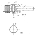
- FIG 3 there is shown an exploded view of a portion of the coupling and brake combination.
- the same or corresponding parts have been given the same reference numerals as in Figures 1 and 2.
- Figure 3 shows a motor shaft 9, and a hub 4 which supports a brake disk (not shown).
- the hub 4 is sized to fit on the motor shaft 9 and has key-ways (not shown) to prevent mutual rotation between the shaft 9 and the hub 4.
- the hub 4 has a longitudinally extending cylindrical sleeve portion 20 which has one or more longitudinal slits 23. It also has an outwardly facing annular groove 21 in its outer cylindrical surface.
- a metal bellows assembly 11 has a generally cylindrical right hand-end 26 sized to fit over the left-hand end of the cylindrical sleeve forming the extension 20 of the hub 4.
- the metal bellows assembly 11 is held in place on the extension 20 of the hub 4 by means of a locking ring 10b sized to fit around the cylindrical end 26 of the metal bellows 11.
- the locking ring 10b has an inwardly facing annular groove 22 in its inner surface, to receive a spring clip 25.
- the spring clip 25 is shown in Figure 4. As it is located in the annular groove 22, as the locking ring 10b is passed over the sleeve 20, but before it is tightened down, the spring clip 25 comes to rest in the outwardly facing annular groove 21. This serves to locate the locking ring 10b on the sleeve 20.
- the locking ring 10b has a radial split or slot with a tangential bolt 24 passing across it.
- the bolt 24 can be tightened. This urges the radial slot in the locking ring 10b closed, which causes the ring to grip the cylindrical extension 26 of the metal bellows 11 against the outer surface of the extension 20 of the hub 4.
- the tightening also tends to urge the slot 23 in the cylindrical sleeve 20 of the hub 4 in a dosing direction, thereby causing the hub 4 to grip tightly against the motor shaft 9.
- the locking ring 10b serves a dual function of holding the metal bellows 11 to the brake hub 4 and also holding the brake hub 4 to the motor shaft 9. This is particularly advantageous because it dispenses with the need to provide a separate fixing means to prevent longitudinal movement of the brake hub 4 with respect to the motor shaft 9.
- the result is that the flexible coupling can be mounted closer to the motor. This is particularly advantageous in situations where there is a limited amount of available motor shaft, or a limited amount of space for the entire assembly. Such situations are common when a brake is being retrofitted to an existing installation.
- the coupling and brake combination in accordance with the present invention therefor saves a considerable amount of space and allows braking assemblies to be retrofitted to motors in spaces which were previously considered too small.
Landscapes
- Engineering & Computer Science (AREA)
- General Engineering & Computer Science (AREA)
- Power Engineering (AREA)
- Mechanical Engineering (AREA)
- Physics & Mathematics (AREA)
- Electromagnetism (AREA)
- Braking Arrangements (AREA)
- Connection Of Motors, Electrical Generators, Mechanical Devices, And The Like (AREA)
Abstract
Description
for example to the A-bearing case of a servomotor, or the motor housing. The
Claims (6)
- A coupling and brake combination for a motor, preferably an electric motor, the brake having a flange (1) for directly connecting the combination to the correspondingly shaped part of the motor housing, wherein the brake is attachable by means of a hub (4) on the motor shaft (9) of the motor, characterized in that the hub (4) connects directly to a metal bellows coupling (11) for transmission of motor rotation to a second shaft and is provided with an outwardly axially projecting tube-like slotted projection (20) also mountable directly on the motor shaft (9) wherein the flexible metal bellows coupling (11) has a cylindrical gripping end which is mounted over the axially projecting tube-like slotted projection (20), a locking ring (10b) being provided to hold the cylindrical gripping end of the flexible metal bellows coupling to the projection (20) and simultaneously hold the projection (20) to the motor shaft (9).
- A combination according to claim 1 characterized in that the end of the flexible metal bellows (11) remote from the motor shaft (9) is clamped to a second shaft (12) by being sandwiched between a split sleeve mounted on the shaft and a split locking ring (10a) clamping down on the outer circumference of the end of the said remote end of the bellows.
- A combination in accordance with any preceding claim characterized in that the flange (1) comprises a housing accommodating the various components of the brake.
- A combination in accordance with any preceding claim characterized in that the brake consists of an electromagnet coil (2), an armature plate (3), the hub (4), at least one brake disk (5), at least two brake pads (6) and at lest one spring (8) that presses the armature plate (3) in the braking direction.
- A combination in accordance with any preceding claim characterized in that the flange (1) is rectangular, preferably square.
- A method of retrofitting an electric motor by installing a brake and coupling combination in accordance with any preceding claim to the A bearing side of the motor.
Applications Claiming Priority (3)
| Application Number | Priority Date | Filing Date | Title |
|---|---|---|---|
| DE20105746U DE20105746U1 (en) | 2001-04-02 | 2001-04-02 | Clutch-brake combination |
| DE20105746U | 2001-04-02 | ||
| PCT/EP2002/003548 WO2002084841A2 (en) | 2001-04-02 | 2002-03-28 | Coupling and brake combination |
Publications (2)
| Publication Number | Publication Date |
|---|---|
| EP1374368A2 EP1374368A2 (en) | 2004-01-02 |
| EP1374368B1 true EP1374368B1 (en) | 2005-08-31 |
Family
ID=7955220
Family Applications (1)
| Application Number | Title | Priority Date | Filing Date |
|---|---|---|---|
| EP02742867A Expired - Lifetime EP1374368B1 (en) | 2001-04-02 | 2002-03-28 | Coupling and brake combination |
Country Status (6)
| Country | Link |
|---|---|
| US (1) | US20040108177A1 (en) |
| EP (1) | EP1374368B1 (en) |
| KR (1) | KR100743484B1 (en) |
| CN (1) | CN1258653C (en) |
| DE (2) | DE20105746U1 (en) |
| WO (1) | WO2002084841A2 (en) |
Families Citing this family (9)
| Publication number | Priority date | Publication date | Assignee | Title |
|---|---|---|---|---|
| DE10335639A1 (en) * | 2003-08-04 | 2005-03-03 | Chr. Mayr Gmbh + Co Kg | Clutch brake combination |
| US20060010072A1 (en) * | 2004-03-02 | 2006-01-12 | Ori Eisen | Method and system for identifying users and detecting fraud by use of the Internet |
| US20060079335A1 (en) * | 2004-10-11 | 2006-04-13 | Wieslaw Muskus | Method and apparatus for coupling components |
| DE102006016434A1 (en) * | 2006-04-07 | 2007-10-11 | Chr. Mayr Gmbh & Co. Kg | Square brake |
| WO2008110186A1 (en) * | 2007-03-14 | 2008-09-18 | Zenergy Power Gmbh | Torque transmission means for the rotationally fixed connection of a shaft and a rotor |
| JP5779469B2 (en) | 2011-09-30 | 2015-09-16 | アスモ株式会社 | motor |
| CN106195071A (en) * | 2016-08-30 | 2016-12-07 | 浙江玛拓驱动设备有限公司 | A kind of square brake assembly |
| DE102017105736B4 (en) * | 2017-03-17 | 2019-02-14 | Schaeffler Technologies AG & Co. KG | Adjustment device for an internal combustion engine |
| CN108667210B (en) * | 2018-06-29 | 2024-08-27 | 无锡新宏泰电器科技股份有限公司 | Braking type motor |
Family Cites Families (8)
| Publication number | Priority date | Publication date | Assignee | Title |
|---|---|---|---|---|
| US3338349A (en) * | 1966-11-17 | 1967-08-29 | Warner Electric Brake & Clutch | Electric motor mounted magnetic friction brake |
| US4445596A (en) * | 1981-09-08 | 1984-05-01 | Facet Enterprises, Inc. | Electromagnetically released spring applied friction brake with torque booster and driving force distributor |
| DE4126672C2 (en) * | 1991-08-13 | 1997-10-23 | Sew Eurodrive Gmbh & Co | Electromagnetically operated brake |
| EP0786852B1 (en) * | 1996-01-24 | 2000-09-20 | Siemens Aktiengesellschaft | Electric drive |
| DE19733169B4 (en) * | 1997-07-31 | 2005-06-16 | Chr. Mayr Gmbh & Co. Kg | Electromagnetically released friction safety brake with two independent brake circuits |
| DE19812223A1 (en) * | 1998-03-19 | 1999-09-23 | Mayr Christian Gmbh & Co Kg | Corrugated tube transmits torque from one shaft to another |
| US6161659A (en) * | 1998-09-29 | 2000-12-19 | Inertia Dynamics, Inc. | Electromagnetic disk brake with rubber friction disk braking surface |
| DE19954590A1 (en) * | 1999-11-12 | 2001-05-17 | Linde Ag | Drive arrangement e.g. for forklift truck, has permanent magnet electric motor with rotor, stator and differential gear integrated into rotor of electric motor, which forms central part of wheel axle |
-
2001
- 2001-04-02 DE DE20105746U patent/DE20105746U1/en not_active Expired - Lifetime
-
2002
- 2002-03-28 DE DE60205878T patent/DE60205878T2/en not_active Expired - Lifetime
- 2002-03-28 CN CNB028010361A patent/CN1258653C/en not_active Expired - Lifetime
- 2002-03-28 KR KR1020027016077A patent/KR100743484B1/en active IP Right Grant
- 2002-03-28 EP EP02742867A patent/EP1374368B1/en not_active Expired - Lifetime
- 2002-03-28 US US10/473,283 patent/US20040108177A1/en not_active Abandoned
- 2002-03-28 WO PCT/EP2002/003548 patent/WO2002084841A2/en active IP Right Grant
Also Published As
| Publication number | Publication date |
|---|---|
| DE20105746U1 (en) | 2001-05-31 |
| KR20030010642A (en) | 2003-02-05 |
| CN1460159A (en) | 2003-12-03 |
| KR100743484B1 (en) | 2007-07-30 |
| DE60205878T2 (en) | 2006-05-24 |
| DE60205878D1 (en) | 2005-10-06 |
| CN1258653C (en) | 2006-06-07 |
| US20040108177A1 (en) | 2004-06-10 |
| WO2002084841A2 (en) | 2002-10-24 |
| EP1374368A2 (en) | 2004-01-02 |
| WO2002084841A3 (en) | 2002-12-12 |
Similar Documents
| Publication | Publication Date | Title |
|---|---|---|
| US8550219B2 (en) | Rectangular, electromagnetically releasing dual-circuit spring-pressure brake | |
| US6202804B1 (en) | Electromagnetically releasable friction safety brake | |
| US7997390B2 (en) | Automatic spring-loaded brake for industrial truck | |
| US5931268A (en) | Electrical actuation mechanism suitable for a disc brake assembly | |
| EP2633605B1 (en) | Brake | |
| US20070107998A1 (en) | Coupling/brake combination | |
| US7073641B2 (en) | Braking system with safe torque take-up | |
| EP1374368B1 (en) | Coupling and brake combination | |
| WO1997030294A9 (en) | Electrical disc brake actuation mechanism | |
| KR20080015414A (en) | External-mounted brake for a driving disk | |
| CN112228479A (en) | Brake for elevator traction machine and implementation method thereof | |
| KR20020059680A (en) | Actuator comprising a sleeve support | |
| US20060169550A1 (en) | Electromagnetic brake assembly | |
| EP0096553A1 (en) | Disc assemblies for brakes | |
| US20060151254A1 (en) | Elevator brake | |
| US4865172A (en) | Combination brake and inching device | |
| US5899441A (en) | Chain hoist with a brake acting on both sides of the clutch | |
| US6889801B2 (en) | Transmission brake | |
| US5389049A (en) | Pre-assembled disc stack having preset tolerance for use in drives, brakes and combinations thereof | |
| CN211183696U (en) | Motor brake device | |
| CA2472036A1 (en) | Elevator brake | |
| CN219413331U (en) | Brake device | |
| KR100502703B1 (en) | Electromagnetically Releasable Friction Safety Brake | |
| JPH0621392U (en) | Drive motor braking mechanism | |
| CN218873954U (en) | Large-tonnage hard broaching machine with power-off protection function |
Legal Events
| Date | Code | Title | Description |
|---|---|---|---|
| PUAI | Public reference made under article 153(3) epc to a published international application that has entered the european phase |
Free format text: ORIGINAL CODE: 0009012 |
|
| 17P | Request for examination filed |
Effective date: 20030912 |
|
| AK | Designated contracting states |
Kind code of ref document: A2 Designated state(s): AT BE CH CY DE DK ES FI FR GB GR IE IT LI LU MC NL PT SE TR |
|
| 17Q | First examination report despatched |
Effective date: 20040914 |
|
| GRAP | Despatch of communication of intention to grant a patent |
Free format text: ORIGINAL CODE: EPIDOSNIGR1 |
|
| RBV | Designated contracting states (corrected) |
Designated state(s): DE ES FR GB IT |
|
| GRAS | Grant fee paid |
Free format text: ORIGINAL CODE: EPIDOSNIGR3 |
|
| GRAA | (expected) grant |
Free format text: ORIGINAL CODE: 0009210 |
|
| AK | Designated contracting states |
Kind code of ref document: B1 Designated state(s): DE ES FR GB IT |
|
| REG | Reference to a national code |
Ref country code: GB Ref legal event code: FG4D |
|
| REF | Corresponds to: |
Ref document number: 60205878 Country of ref document: DE Date of ref document: 20051006 Kind code of ref document: P |
|
| PG25 | Lapsed in a contracting state [announced via postgrant information from national office to epo] |
Ref country code: ES Free format text: LAPSE BECAUSE OF FAILURE TO SUBMIT A TRANSLATION OF THE DESCRIPTION OR TO PAY THE FEE WITHIN THE PRESCRIBED TIME-LIMIT Effective date: 20051212 |
|
| PG25 | Lapsed in a contracting state [announced via postgrant information from national office to epo] |
Ref country code: GB Free format text: LAPSE BECAUSE OF NON-PAYMENT OF DUE FEES Effective date: 20060328 |
|
| PLBE | No opposition filed within time limit |
Free format text: ORIGINAL CODE: 0009261 |
|
| STAA | Information on the status of an ep patent application or granted ep patent |
Free format text: STATUS: NO OPPOSITION FILED WITHIN TIME LIMIT |
|
| 26N | No opposition filed |
Effective date: 20060601 |
|
| EN | Fr: translation not filed | ||
| PG25 | Lapsed in a contracting state [announced via postgrant information from national office to epo] |
Ref country code: FR Free format text: LAPSE BECAUSE OF FAILURE TO SUBMIT A TRANSLATION OF THE DESCRIPTION OR TO PAY THE FEE WITHIN THE PRESCRIBED TIME-LIMIT Effective date: 20061027 |
|
| GBPC | Gb: european patent ceased through non-payment of renewal fee |
Effective date: 20060328 |
|
| PG25 | Lapsed in a contracting state [announced via postgrant information from national office to epo] |
Ref country code: FR Free format text: LAPSE BECAUSE OF FAILURE TO SUBMIT A TRANSLATION OF THE DESCRIPTION OR TO PAY THE FEE WITHIN THE PRESCRIBED TIME-LIMIT Effective date: 20050831 |
|
| PG25 | Lapsed in a contracting state [announced via postgrant information from national office to epo] |
Ref country code: IT Free format text: LAPSE BECAUSE OF NON-PAYMENT OF DUE FEES Effective date: 20080328 |
|
| REG | Reference to a national code |
Ref country code: DE Ref legal event code: R084 Ref document number: 60205878 Country of ref document: DE |
|
| PGFP | Annual fee paid to national office [announced via postgrant information from national office to epo] |
Ref country code: DE Payment date: 20210323 Year of fee payment: 20 |
|
| PGFP | Annual fee paid to national office [announced via postgrant information from national office to epo] |
Ref country code: IT Payment date: 20210331 Year of fee payment: 20 |
|
| REG | Reference to a national code |
Ref country code: DE Ref legal event code: R071 Ref document number: 60205878 Country of ref document: DE |