EP1373039B2 - Brake force transmission device for a brake force amplifier - Google Patents
Brake force transmission device for a brake force amplifier Download PDFInfo
- Publication number
- EP1373039B2 EP1373039B2 EP02702329A EP02702329A EP1373039B2 EP 1373039 B2 EP1373039 B2 EP 1373039B2 EP 02702329 A EP02702329 A EP 02702329A EP 02702329 A EP02702329 A EP 02702329A EP 1373039 B2 EP1373039 B2 EP 1373039B2
- Authority
- EP
- European Patent Office
- Prior art keywords
- transmission device
- spring
- control housing
- reaction element
- force
- Prior art date
- Legal status (The legal status is an assumption and is not a legal conclusion. Google has not performed a legal analysis and makes no representation as to the accuracy of the status listed.)
- Expired - Lifetime
Links
- 230000005540 biological transmission Effects 0.000 title claims description 23
- 238000006243 chemical reaction Methods 0.000 claims description 32
- 230000002093 peripheral effect Effects 0.000 claims description 5
- 230000007423 decrease Effects 0.000 claims description 2
- 230000004048 modification Effects 0.000 claims 1
- 238000012986 modification Methods 0.000 claims 1
- 230000000630 rising effect Effects 0.000 claims 1
- 239000000463 material Substances 0.000 description 5
- 230000003321 amplification Effects 0.000 description 3
- 238000013459 approach Methods 0.000 description 3
- 238000010276 construction Methods 0.000 description 3
- 238000013461 design Methods 0.000 description 3
- 238000003199 nucleic acid amplification method Methods 0.000 description 3
- 230000001105 regulatory effect Effects 0.000 description 3
- 230000006835 compression Effects 0.000 description 2
- 238000007906 compression Methods 0.000 description 2
- 238000012546 transfer Methods 0.000 description 2
- 230000003247 decreasing effect Effects 0.000 description 1
- 238000011161 development Methods 0.000 description 1
- 230000009365 direct transmission Effects 0.000 description 1
- 238000006073 displacement reaction Methods 0.000 description 1
- 230000000694 effects Effects 0.000 description 1
- 239000012530 fluid Substances 0.000 description 1
- 238000004519 manufacturing process Methods 0.000 description 1
- 239000002184 metal Substances 0.000 description 1
- 238000000034 method Methods 0.000 description 1
- 230000002787 reinforcement Effects 0.000 description 1
- 238000007789 sealing Methods 0.000 description 1
Images

Classifications
-
- B—PERFORMING OPERATIONS; TRANSPORTING
- B60—VEHICLES IN GENERAL
- B60T—VEHICLE BRAKE CONTROL SYSTEMS OR PARTS THEREOF; BRAKE CONTROL SYSTEMS OR PARTS THEREOF, IN GENERAL; ARRANGEMENT OF BRAKING ELEMENTS ON VEHICLES IN GENERAL; PORTABLE DEVICES FOR PREVENTING UNWANTED MOVEMENT OF VEHICLES; VEHICLE MODIFICATIONS TO FACILITATE COOLING OF BRAKES
- B60T13/00—Transmitting braking action from initiating means to ultimate brake actuator with power assistance or drive; Brake systems incorporating such transmitting means, e.g. air-pressure brake systems
- B60T13/10—Transmitting braking action from initiating means to ultimate brake actuator with power assistance or drive; Brake systems incorporating such transmitting means, e.g. air-pressure brake systems with fluid assistance, drive, or release
- B60T13/24—Transmitting braking action from initiating means to ultimate brake actuator with power assistance or drive; Brake systems incorporating such transmitting means, e.g. air-pressure brake systems with fluid assistance, drive, or release the fluid being gaseous
- B60T13/46—Vacuum systems
- B60T13/52—Vacuum systems indirect, i.e. vacuum booster units
- B60T13/573—Vacuum systems indirect, i.e. vacuum booster units characterised by reaction devices
- B60T13/575—Vacuum systems indirect, i.e. vacuum booster units characterised by reaction devices using resilient discs or pads
Definitions
- the invention relates to a brake force transmission device for a brake booster with an elastic reaction element, an input member having an associated active surface, an output member having an associated active surface and a first gear ratio, which is defined by a standing in operative connection with the reaction element ratio of the active surfaces.
- a transmission device is, for example, Japanese Utility Model JP-U-61-205858 known.
- the transfer means has a spring biased movable pressure piece disposed on an input side (or an output side), which causes a step increase in gain ratio at a given input force by area ratio change on the input side (or output side).
- DE 199 16 579 A1 describes the preamble of claim 1.
- the invention is therefore based on a transmission device resulting from the preamble of claim 1 genus.
- Object of the present invention is to provide a transmission device which is easily integrated with a particularly small size in a brake booster of the standard type. It should therefore be possible to use the transmission device as desired in already existing brake booster without having to make expensive new or change constructions.
- the invention in principle is that is displaced by the deformation of the reaction element of the switching ring against the force of the spring to the input song until the retroactive on the control housing surface of the reaction element is increased around the annular surface of the switching ring.
- This results in a smaller effective area at the entrance and thus an increase in the transmission ratio of the forces.
- this means that after the stop of the switching ring on the control housing acting on the input member reaction of the output member is reduced. The driver can thus achieve the same braking effect with reduced foot force.
- the spring assembly is, as will be explained in more detail below, very simple.
- the spring assembly is still a self-contained assembly that is integrally inserted in the assembly of the brake booster in the control housing.
- the same can also apply to the switching ring, which may be integrally connected to the spring assembly but advantageously forms a separate unit.
- the advantage of these measures is, in particular, in that both the spring assembly and the switching ring in different embodiments can be kept in stock with which then the control housing is equipped as needed and desired course of reinforcement.
- the spring assembly is constructed substantially symmetrical. It is essential only that the two holding elements can be moved against each other against the force of the spring.
- the stop element further ensures that the two holding elements are united into one unit and none of the retaining elements can be lost.
- the force is uniquely determined by the choice of the spring and the choice of the distance between the two holding elements to each other, with which the two holding elements are biased to each other.
- the first holding elements can engage directly on the reaction element by means of a projection extending through the second holding element. But it is also conceivable that the first holding element acts only indirectly via a pressure piece on the reaction element.
- the advantage of this is that the pressure piece can be selected according to the course of the desired gain. Since, as already explained above, with regard to the separately insertable switching ring a selection is possible, can be largely varied by the combination of the switching ring with a pressure piece, the course of the calibration line of the gain. This can be largely adapted to the respective needs by the choice of the switching ring of the pressure element and the spring element, the amplification behavior of the brake booster as a function of the input force.
- a further advantage is that said elements can be retrofitted and thus allow an adjustment of the amplifier already in the series.
- the switching ring can be performed with its inner surface both through the outer surface of the neck, as well as with its outer circumferential surface on the inner circumferential surface of a projection on the control housing.
- the first holding elements engages only indirectly via a pressure piece on the reaction element, however, then only a guide of the switching ring on its outer lateral surface is possible.
- the switching ring does not strike directly on the control housing, but indirectly via the second holding element, which it acts on.
- the switching ring can be very simple ausgestaltet so that it still consists of a simple cylindrical ring.
- a larger stop surface by the second holding element for receiving a sufficiently large spring anyway in the radial direction must have a greater extent.
- a simplified production can also be achieved by the feature combination according to claim 4. Since the fixed ring can also serve as a guide for the switching ring, can be influenced by an appropriate dimensioning of the inner recess of the fixed ring and the outer diameter of the switching ring, the strength of the switching ring and thus the course of the characteristic of the gain.
- a further simplification for the construction of the transmission device according to the invention can be achieved by the measures according to claim 5.
- the control housing serves at the same time for the axial guidance for the second holding element and as a stop.
- the walls of the guide grooves are thus doubly utilized by serving at the same time to guide in the longitudinal direction and as a stop.
- the feature combination according to claim 6 is recommended in development of the invention.
- the spring can influence the course of the characteristic of the gain by the characteristic curve of the spring is selected accordingly.
- the approach can be connected directly in one piece with the first holding element according to the features of claim 10. In order to save material and a suitable combination of materials, however, the holding element can also be riveted to the approach.
- An important aspect of the invention is that, as explained in connection with claim 8, it is inserted in a particularly appropriate manner in a regulated braking system. This applies in particular when the distribution of the braking forces on the individual wheels or wheel groups is regulated as a function of the slip on the respective wheel or on the wheels in the regulated braking system. This ensures that with little effort at low pedal force nevertheless a sufficiently large brake pressure can be generated. On the other hand, the controlled distribution of braking forces ensures that the vehicle does not get out of the lane by slipping on one or more wheels.
- the advantage of the invention is based essentially on the following facts.
- the present operating principle is based essentially and in a simple manner on a prestressed spring, which is placed in axial action between the valve piston and the piston. In this case, function-related attacks are provided, with a direct transmission is ensured when driving through the amplifier.
- the preferred design features are as follows. It is provided in a simple manner bounded compression spring. It is used a very simple design spring element.
- the control housing is provided with a fixed ring, which is designed very simply as a force-absorbing disc. This fixed ring can bear against the end face of a stepped bore in the control housing wherein grooves are recessed in the wall of the stepped bore, which serve both as a guide, as well as a stop. In other words, the following is particularly important in the construction described herein.
- the present principle is based essentially, and in a simple manner, on a preloaded spring, which is placed in the axial action between the valve piston and the annular piston, and cooperates with some function-related attacks, with a direct power transmission is ensured in the für Kunststoffn.
- Particularly noteworthy structural features are the compression spring (s) (5), which is tied up in a simple manner, and an inexpensive power transmission element.
- a control housing portion (4) behind the force-absorbing disc (1) takes multifunctional, the forces of the switching ring (2), and also serves to guide the stop plate as a second holding element (6) with stop.
- the stop disc (6) biases the spring forward, passes the reaction forces of the annular piston (2) to the spring on, and is stop of the annular piston, and transfer member during the für Kunststoffn.
- the invention is particularly effective in connection with an electronically controlled braking force distribution, since in case of failure of the ABS (anti-lock braking system) usually also the failure of the electronic brake force distribution (EBV) occurs. In this case, the driver can still dose the brake pressure well on the steep branch of the amplifier characteristic. This is in contrast to systems with panic brake function such.
- Basically known brake booster ideally have considered over the entire operating range up to the so-called control point over a constant gear ratio, wherein the induced output force (foot force and boost force) increases linearly over the input force (foot force).
- the ratio which essentially influences the pedal feel of the driver is defined by the ratio of the active surface (d4) associated with the output member to the active surface (d3) associated with the input member.
- the ratio of the active surface (d4) associated with the output member to the active surface (d3) associated with the input member.
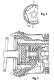
- a transmission device 20 comprises, in addition to other, the brake booster attributable parts, which have no decisive influence and are therefore not described below, in a control housing 8 with a first sealing seat 21 movably arranged input member 22 with a valve piston 23 and an output member 24th for actuating a not signed master cylinder.
- a control housing 8 with a first sealing seat 21 movably arranged input member 22 with a valve piston 23 and an output member 24th for actuating a not signed master cylinder.
- Between the input member 22 and the output member 24 is a preferably disc-shaped, and made of plastic material or rubber material elastic reaction element 7, which is surrounded on all sides by surfaces of parts of the transmission device 20, in other words, encapsulated as it were between movable walls.
- the elastic reaction element 7 behaves under pressure as an incompressible fluid according to the laws of volume constancy and acts as a kind of mediator between the introduced via the input member 22 foot forces and the brake reaction forces, which act back from the vehicle brake system to the driver. Consequently, at each brake actuation position, a force balance prevails on the reaction element 7.
- the reaction element 7 is seated in a Fig. 1 to the left open pot 25, which is formed by a first bore 26 in the control housing 8 and a fixed ring 1, which is supported on the edge 28 of a second bore 27 of the control housing 8.
- the pot 25 has an inlet opening 29 in which, in the drawing front end, the output song 24 is guided.
- the output member 24 goes to his in Fig. 1 right end in a plate 10 over, which closes the pot 25 and against the in Fig. 1 to the left-facing wall of the reaction element 7 is applied.
- the reaction element 7 is supported against the fixed ring 1, which in turn rests against the peripheral edge 28 or step between the first bore 26 and the second bore 27.
- the area for the plate 10 is indicated by the value d4.
- the fixed ring 1 has inside an opening, which is indicated by the value d3 as the area of the opening.
- a switching ring 2 is guided, which is displaceable relative to the fixed ring 1 in the longitudinal direction of the amplifier.
- a spring element is composed of a first holding element 3, a second holding element 6 and a spring 5.
- the spring 5 biases the two holding elements 3 and 6 against each other, so that they can be moved against each other only with a certain force.
- the maximum distance between the two holding elements against each other is determined by a stop 12 which is arranged on a projection 13 of the first holding element 3.
- the first holding element 3 is provided with a projection 13, which may be formed together with the holding element as a single continuous piece. But it is also useful to approach 13, as in Fig. 1 shown to perform as a rivet.
- the rivet part can be selected from a material having suitable strength, while the first holding element 3 is formed from a shapeable metal sheet.
- a stop 12 is provided, which is designed as a circumferential projection. By this stop 12 ensures that the second support member 6 can only remove by a predetermined distance from the first support member 3.
- the projection 13 can protrude into the interior of the switching ring 2.
- a rivet part 13 can also be connected to a pressure piece 31, which protrudes through the switching ring 2 and acts on the reaction element 7.
- the guidance of the second holding element 6 in the control housing 8 is important.
- This guide is done by means of guide grooves 4, which are incorporated in the inner circumferential surface of the second bore 27 distributed over the circumference of the bore.
- the second support member 6 is provided with appropriately designed guide lugs 15 which engage in the grooves 4 as in Fig. 2 is shown.
- An end wall 11 in each groove forms a stop for the guide lugs 15, so that in a stop of the guide lugs 15 on the respective end wall 11 a, on the second support member 6 in Fig. 1 rightward force is absorbed by the control housing 8.
- the others, in Fig. 1 shown components, are not essential to the present invention and are therefore not described in detail this point.
- Fig. 1 The operation of the embodiment according to Fig. 1 is as follows. Will be in the in Fig. 1 shown Position the input member 22 in Fig. 1 shifted to the left, the pressure piece 31 and the switching ring 2 engage the reaction element 7. Thus, a surface d3 is effective on the reaction element 7, while the reaction element 7 acts on the output member 24 with the surface d4. By the ratio of these two surfaces, the amplification ratio is fixed in this working state of the amplifier. In this case, switching ring and pressure piece 31 move in parallel with each other, since the spring 5 is so stiff that it does not yield in this area of the force acting on that input member 22 input force.
- FIG. 3 shown second embodiment is compared to the embodiment according to Fig. 1 only slightly changed.
- the main difference is that instead of a spring 5, two mutually parallel switched springs 5 and 32 are used.
- the inner seated second spring 32 has a relation to the first spring 5 lower spring constant. In this way can be set up on the same space a larger and more accurate dosed spring force.
Description
Die Erfindung betrifft eine Bremskraftübertragungseinrichtung für einen Bremskraftverstärker mit einem elastischen Reaktionselement, einem Eingangsglied mit einer zugeordneten Wirkfläche, einem Ausgangsglied mit einer zugeordneten Wirkfläche und mit einem ersten Übersetzungsverhältnis, welches durch ein, in Wirkverbindung mit dem Reaktionselement stehendes Verhältnis der Wirkflächen definiert ist.The invention relates to a brake force transmission device for a brake booster with an elastic reaction element, an input member having an associated active surface, an output member having an associated active surface and a first gear ratio, which is defined by a standing in operative connection with the reaction element ratio of the active surfaces.
Eine Übertragungseinrichtung ist beispielsweise aus dem japanischen Gebrauchsmuster
Die Erfindung geht daher aus von einer Übertragungseinrichtung der sich aus dem Oberbegriff des Anspruchs 1 ergebenden Gattung. Aufgabe der vorliegenden Erfindung ist es, eine Übertragungseinrichtung bereitzustellen, welche mit einer besonders geringen Baugröße einfach in einen Bremskraftverstärker vom Standardtyp integrierbar ist. Es soll folglich ermöglicht werden, die Übertragungseinrichtung nach Wunsch auch in bereits bestehende Bremskraftverstärker einsetzen zu können, ohne teure Neu- oder Änderungskonstruktionen vornehmen zu müssen.The invention is therefore based on a transmission device resulting from the preamble of claim 1 genus. Object of the present invention is to provide a transmission device which is easily integrated with a particularly small size in a brake booster of the standard type. It should therefore be possible to use the transmission device as desired in already existing brake booster without having to make expensive new or change constructions.
Die Aufgabe wird durch die sich aus dem Anspruch 1, ergebende Merkmalskombination gelöst.The object is achieved by the combination of features resulting from the claim 1.
Bei der Lösung nach Anspruch 1 besteht die Erfindung im Prinzip darin, daß durch die Verformung des Reaktionselementes der Schaltring entgegen der Kraft der Feder zum Eingangslied hin solange verschoben wird, bis die auf das Steuergehäuse rückwirkende Fläche des Reaktionselementes um die Ringfläche des Schaltringes vermehrt ist. Hierdurch ergibt sich eine kleinere Wirkfläche am Eingang und damit auch eine Vergrößerung des Übersetzungsverhältnisses der Kräfte. Anders ausgedrückt bedeutet das, daß nach dem Anschlag des Schaltringes an dem Steuergehäuse die auf das Eingangsglied einwirkende Rückwirkung des Ausgangsgliedes vermindert wird. Der Fahrer kann somit bei verminderter Fußkraft den gleichen Bremseffekt erreichen.In the solution according to claim 1, the invention in principle is that is displaced by the deformation of the reaction element of the switching ring against the force of the spring to the input song until the retroactive on the control housing surface of the reaction element is increased around the annular surface of the switching ring. This results in a smaller effective area at the entrance and thus an increase in the transmission ratio of the forces. In other words, this means that after the stop of the switching ring on the control housing acting on the input member reaction of the output member is reduced. The driver can thus achieve the same braking effect with reduced foot force.
Das Federpaket ist, wie weiter unten noch näher erläutert wird, sehr einfach aufgebaut. Das Federpaket ist weiterhin eine in sich abgeschlossene Baueinheit, die beim Zusammenbau des Bremskraftverstärkers einstückig in das Steuergehäuse eingefügt wird. Entsprechendes kann auch für den Schaltring gelten, der zwar einstückig mit dem Federpaket verbunden sein kann vorteilhaft aber eine getrennte Einheit bildet. Der Vorteil dieser Maßnahmen liegt insbesondere darin, in das sowohl das Federpaket als auch der Schaltring in verschiedenen Ausführungsformen am Lager gehalten werden können mit denen dann das Steuergehäuse je nach Bedarf und gewünschtem Verlauf der Verstärkung bestückt wird.The spring assembly is, as will be explained in more detail below, very simple. The spring assembly is still a self-contained assembly that is integrally inserted in the assembly of the brake booster in the control housing. The same can also apply to the switching ring, which may be integrally connected to the spring assembly but advantageously forms a separate unit. The advantage of these measures is, in particular, in that both the spring assembly and the switching ring in different embodiments can be kept in stock with which then the control housing is equipped as needed and desired course of reinforcement.
Das Federpaket ist im wesentlichen symmetrisch aufgebaut. Wesentlich dabei ist nur, daß die beiden Halteelemente gegen die Kraft der Feder gegeneinander verschoben werden können. Das Anschlagelement sorgt weiterhin dafür, daß die beiden Halteelemente zu einer Einheit vereint sind und keines der Halteelemente verlorengehen kann. Außerdem ist durch die Wahl der Feder und die Wahl des Abstandes der beiden Halteelemente zueinander die Kraft eindeutig bestimmbar, mit der die beiden Halteelemente zueinander vorgespannt sind.The spring assembly is constructed substantially symmetrical. It is essential only that the two holding elements can be moved against each other against the force of the spring. The stop element further ensures that the two holding elements are united into one unit and none of the retaining elements can be lost. In addition, the force is uniquely determined by the choice of the spring and the choice of the distance between the two holding elements to each other, with which the two holding elements are biased to each other.
Das erste Halteelemente kann durch einen, durch das zweite Halteelement hindurch reichenden Ansatz direkt an dem Reaktionselement angreifen. Es ist aber auch denkbar, daß das erste Halteelement nur mittelbar über ein Druckstück auf das Reaktionselement einwirkt. Der Vorteil hiervon ist, daß das Druckstück entsprechend dem Verlauf der gewünschten Verstärkung ausgewählt werden kann. Da auch, wie weiter oben schon erläutert, hinsichtlich des getrennt einfügbaren Schaltringes eine Auswahl möglich ist, läßt sich durch die Kombination des Schaltringes mit einem Druckstück der Verlauf der Kenlinie der Verstärkung weitgehend variieren. Damit kann durch die Wahl des Schaltringes des Druckstücks und des Federelementes das Verstärkungsverhalten des Bremskraftverstärkers in Abhängigkeit von der Eingangskraft weitgehend den jeweiligen Bedürfnissen angepaßt werden. Vorteilhaft ist weiterhin, daß die genannten Elemente nachgerüstet werden können und somit eine Anpassung des bereits in der Serie befindlichen Verstärkers ermöglichen.The first holding elements can engage directly on the reaction element by means of a projection extending through the second holding element. But it is also conceivable that the first holding element acts only indirectly via a pressure piece on the reaction element. The advantage of this is that the pressure piece can be selected according to the course of the desired gain. Since, as already explained above, with regard to the separately insertable switching ring a selection is possible, can be largely varied by the combination of the switching ring with a pressure piece, the course of the calibration line of the gain. This can be largely adapted to the respective needs by the choice of the switching ring of the pressure element and the spring element, the amplification behavior of the brake booster as a function of the input force. A further advantage is that said elements can be retrofitted and thus allow an adjustment of the amplifier already in the series.
Dabei kann der Schaltring mit seiner Innenfläche sowohl durch die Außenfläche des Ansatzes geführt sein, als auch mit seiner äußeren Mantelfläche an der inneren Mantelfläche eines Ansatzes an dem Steuergehäuse. Für den Fall, daß das erste Halteelemente nur mittelbar über ein Druckstück an dem Reaktionselement angreift, ist dann allerdings nur eine Führung des Schaltringes an seiner äußeren Mantelfläche möglich.In this case, the switching ring can be performed with its inner surface both through the outer surface of the neck, as well as with its outer circumferential surface on the inner circumferential surface of a projection on the control housing. In the event that the first holding elements engages only indirectly via a pressure piece on the reaction element, however, then only a guide of the switching ring on its outer lateral surface is possible.
Der Schaltringschlägt nicht direkt am Steuergehäuse an, sondern mittelbar über das zweite Halteelement, auf welches er einwirkt. Hierdurch läßt sich der Schaltring sehr einfach ausgestalteten so daß er noch aus einem einfachen zylindrischen Ring besteht. Weiterhin läßt sich durch die Ausgestaltung in sehr einfache Weise eine größere Anschlagfläche erreichen, indem das zweite Halteelement zur Aufnahme einer hinreichend großen Feder ohnedies in radialer Richtung eine größere Erstreckung aufweisen muß.The switching ring does not strike directly on the control housing, but indirectly via the second holding element, which it acts on. As a result, the switching ring can be very simple ausgestaltet so that it still consists of a simple cylindrical ring. Furthermore, can be achieved by the design in a very simple manner, a larger stop surface by the second holding element for receiving a sufficiently large spring anyway in the radial direction must have a greater extent.
Eine vereinfachte Herstellung läßt sich auch durch die Merkmalskombination nach Anspruch 4 erreichen. Da der fixierte Ring gleichzeitig als Führung für den Schaltring dienen kann, läßt sich durch eine entsprechende Dimensionierung der inneren Ausnehmung des fixierten Ringes und des äußeren Durchmessers des Schaltringes die Stärke des Schaltringes und damit der Verlauf der Kennlinie der Verstärkung beeinflussen.A simplified production can also be achieved by the feature combination according to claim 4. Since the fixed ring can also serve as a guide for the switching ring, can be influenced by an appropriate dimensioning of the inner recess of the fixed ring and the outer diameter of the switching ring, the strength of the switching ring and thus the course of the characteristic of the gain.
Eine weitere Vereinfachung für den Aufbau der erfindungsgemäßen Übertragungseinrichtung läßt sich durch die Maßnahmen nach Anspruch 5 erreichen. Dabei dient das Steuergehäuse gleichzeitig zur axialen Führung für das zweite Halteelement und als Anschlag. Die Wände der Führungsnuten werden somit doppelt ausgenutzt indem sie gleichzeitig zur Führung in Längsrichtung als auch als Anschlag dienen.A further simplification for the construction of the transmission device according to the invention can be achieved by the measures according to
Um eine hinreichende Federkraft trotz kleiner Abmessungen zu erreichen, empfiehlt sich in Weiterbildung der Erfindung die Merkmalskombination nach Anspruch 6. Die Feder kann den Verlauf der Kennlinie der Verstärkung beeinflussen, indem die Kennlinie der Feder entsprechend ausgewählt wird. Der Ansatz kann entsprechend den Merkmalen nach Anspruch 10 direkt einstückig mit dem ersten Halteelement verbunden sein. Zur Ersparnis von Material und zur geeigneten Kombination von Werkstoffen kann das Halteelement aber auch mit dem Ansatz vernietet sein.In order to achieve a sufficient spring force despite small dimensions, the feature combination according to
Ein wichtiger Gesichtspunkt für die Erfindung ist es, daß, wie im Zusammenhang mit Anspruch 8 erläutert, sie in besonders zweckmäßiger Weise in ein geregeltes Bremssystem eingefügt ist. Dies gilt besonders dann, wenn bei dem geregelten Bremssystem die Verteilung der Bremskräfte auf die einzelnen Räder oder Radgruppen in Abhängigkeit von dem Schlupf an den jeweiligen Rad bzw. an den Rädern geregelt ist. Hierdurch wird erreicht, daß mit geringem Aufwand bei geringer Pedalkraft gleichwohl ein hinreichend großer Bremsdruck erzeugt werden kann. Auf der anderen Seite sorgt die geregelte Verteilung der Bremskräfte dafür, daß das Fahrzeug nicht durch Schlupf an einem oder mehreren Rädern aus der Spur gerät.An important aspect of the invention is that, as explained in connection with
Der Vorteil der Erfindung beruht im wesentlichen auf folgenden Fakten. Das hier vorliegende Funktionsprinzip beruht im wesentlichen und in einfacher Weise auf einer vorgespannten Feder, die in axialer Wirkungsweise zwischen Ventilkolben und dem Kolben plaziert ist. Dabei sind funktionsbedingte Anschläge vorgesehen, wobei eine direkte Übertragung beim Durchsteuern des Verstärkers sichergestellt ist. Die bevorzugten Konstruktionsmerkmale bestehen im folgenden. Es ist eine in einfacher Weise gefesselte Druckfeder vorgesehen. Es wird ein sehr einfach aufgebautes Federelementes verwendet. Das Steuergehäuse ist mit einem fixierten Ring versehen, welcher sehr einfach als Kraft aufnehmende Scheibe ausgestaltet ist. Dieser fixierte Ring kann sich gegen die Stirnfläche einer Stufenbohrung in dem Steuergehäuse anlegen wobei in die Wand der Stufenbohrung Nuten eingelassen sind, welche gleichzeitig zur Führung, als auch als Anschlag dienen. Mit anderen Worten ist bei der hier beschriebenen Konstruktion folgendes besonders wichtig.The advantage of the invention is based essentially on the following facts. The present operating principle is based essentially and in a simple manner on a prestressed spring, which is placed in axial action between the valve piston and the piston. In this case, function-related attacks are provided, with a direct transmission is ensured when driving through the amplifier. The preferred design features are as follows. It is provided in a simple manner bounded compression spring. It is used a very simple design spring element. The control housing is provided with a fixed ring, which is designed very simply as a force-absorbing disc. This fixed ring can bear against the end face of a stepped bore in the control housing wherein grooves are recessed in the wall of the stepped bore, which serve both as a guide, as well as a stop. In other words, the following is particularly important in the construction described herein.
Das hier vorliegende Funktionsprinzip beruht im Wesentlichen, und in einfacher Weise, auf einer vorgespannten Feder, die in axialer Wirkungsweise zwischen Ventilkolben und Ringkolben platziert ist, und mit einigen funktionsbedingten Anschlägen zusammenwirkt, wobei eine direkte Kraftübertragung beim Durchsteuern sichergestellt ist. Besonders hervorzuhebende Konstuktionsmerkmale sind die in einfacher Weise gefesselte Druckfeder(n) (5), und ein preiswertes Kraftübertragungsglied. Ein Steuergehäusebereich (4) hinter der kraftaufnehmenden Scheibe (1) nimmt multifunktional, die Kräfte vom Schaltring (2) auf, und dient gleichzeitig zur Führung der Anschlagscheibe als zweites Halteelement (6) mit Anschlag. Die Anschlagscheibe (6) spannt die Feder vor, leitet die Reaktionskräfte des Ringkolbens (2) an die Feder weiter, und ist Anschlag des Ringkolbens, sowie Übertragungsglied beim Durchsteuern.The present principle is based essentially, and in a simple manner, on a preloaded spring, which is placed in the axial action between the valve piston and the annular piston, and cooperates with some function-related attacks, with a direct power transmission is ensured in the Durchsteuern. Particularly noteworthy structural features are the compression spring (s) (5), which is tied up in a simple manner, and an inexpensive power transmission element. A control housing portion (4) behind the force-absorbing disc (1) takes multifunctional, the forces of the switching ring (2), and also serves to guide the stop plate as a second holding element (6) with stop. The stop disc (6) biases the spring forward, passes the reaction forces of the annular piston (2) to the spring on, and is stop of the annular piston, and transfer member during the Durchsteuern.
Die Erfindung ist besonders wirksam in Verbindung mit einer elektronisch geregelten Bremskraftverteilung, da bei Ausfall des ABS (Antiblockiersystem) in der Regel auch der Ausfall der elektronischen Bremskraftverteilung (EBV) auftritt. In diesem Falle kann der Fahrer den Bremsdruck auf dem steilen Ast der Verstärker-Kennlinie noch gut dosieren. Dies steht im Gegensatz zu Systemen mit Panik-Brems-Funktion wie z. B. Bremsassistent (BA) oder mechanischer Bremsassistent (MBA) , die beim Wechseln in eine unendliche (steile) Kennlinie der Bremskraft-Verstärkung deutlich schwieriger beherrschbar sind.The invention is particularly effective in connection with an electronically controlled braking force distribution, since in case of failure of the ABS (anti-lock braking system) usually also the failure of the electronic brake force distribution (EBV) occurs. In this case, the driver can still dose the brake pressure well on the steep branch of the amplifier characteristic. This is in contrast to systems with panic brake function such. B. Brake Assistant (BA) or mechanical brake assist (MBA), which are much more difficult to control when changing into an infinite (steep) characteristic of the brake power gain.
Zwei Ausführungsbeispiele der Erfindung werden nachfolgend anhand der Zeichnung erläutert. Darin zeigt :
-
Fig. 1 eine Übertragungseinrichtung gemäß einer ersten Ausführungsform im Schnitt und in herausgebrochener Darstellung, -
Fig. 2 in herausgebrochener geschnittener Darstellung einen Schnitt durch das Ausführungsbeispiel nachFig. 1 in Höhe der Schnittlinie A-A inFig. 1 , und -
Fig. 3 ein zweites Ausführungsbeispiel der Erfindung.
-
Fig. 1 a transmission device according to a first embodiment in section and in broken-away representation, -
Fig. 2 in cut-out cut representation of a section through the embodiment according toFig. 1 at the level of the intersection AA inFig. 1 , and -
Fig. 3 A second embodiment of the invention.
Nachstehend wird auf den Aufbau und die Funktion der Übertragungseinrichtung 1 detailliert eingegangen, wobei die grundsätzliche Funktion eines Bremskraftverstärkers wie sie beispielhaft der
Grundsätzlich bekannte Bremskraftverstärker verfügen idealisiert betrachtet über den gesamten Betriebsbereich bis hin zu dem sogenannten Aussteuerungspunkt über ein konstantes Übersetzungsverhältnis, wobei die hervorgerufene Ausgangskraft (Fußkraft und Verstärkungskraft) linear über der Eingangskraft (Fußkraft) ansteigt. Ganz grundsätzlich ist die Übersetzung, welche das Pedalgefühl des Fahrers im wesentlichen beeinflusst, durch das Verhältnis der dem Ausgangsglied zugeordneten Wirkfläche (d4) zu der dem Eingangsglied zugeordneten Wirkfläche (d3) definiert. Für höhere Bremsleistungen, das heißt bei höherem Bremskraftniveau wird es als positiv angesehen, den Fahrer stärker zu unterstützen. Es wird mit anderen Worten ein größeres Übersetzungsverhältnis hervorgerufen, wie es beispielsweise der
Eine Übertragungseinrichtung 20 nach der Erfindung umfaßt neben anderen, dem Bremskraftverstärker zuzurechnenden Teilen, welche hier keinen entscheidenden Einfluß haben und deshalb nachstehend nicht beschrieben werden, ein in einem Steuergehäuse 8 mit einem ersten Dichtsitz 21 bewegbar angeordnetes Eingangsglied 22 mit einem Ventilkolben 23 sowie ein Ausgangsglied 24 zur Betätigung eines nicht gezeichneten Hauptbremszylinders. Zwischen dem Eingangsglied 22 und dem Ausgangselement 24 befindet sich ein vorzugsweise scheibenförmiges, und aus Kunststoffwerkstoff oder Gummiwerkstoff bestehendes elastisches Reaktionselement 7, welches allseitig durch Flächen von Teilen der Übertragungseinrichtung 20 umgeben, mit anderen Worten gewissermaßen zwischen beweglichen Wänden gekapselt ist. Das elastische Reaktionselement 7 verhält sich unter Druckbeanspruchung wie ein inkompressibles Fluid nach den Gesetzen der Volumenkonstanz und fungiert gewissermaßen als Mittler zwischen den über das Eingangsglied 22 eingeleiteten Fußkräften und den Bremsreaktionskräften, welche aus dem Fahrzeugbremssystem auf den Fahrzeugführer zurückwirken. Folglich herrscht bei jeder Bremsbetätigungsstellung ein Kraftgleichgewicht an dem Reaktionselement 7.A
Das Reaktionselement 7 sitzt in einem in
Das erste Halteelemente 3 ist mit einem Ansatz 13 versehen, der zusammen mit dem Halteelement als ein einziges durchgehendes Stück ausgeformt sein kann. Es ist aber auch sinnvoll, den Ansatz 13, wie in
Für die vorliegende Erfindung ist die Führung des zweiten Halteelementes 6 in dem Steuergehäuse 8 wichtig. Diese Führung geschieht mit Hilfe von Führungsnuten 4, die in die innere Mantelfläche der zweiten Bohrung 27 über den Umfang der Bohrung verteilt eingearbeitet sind. Zu Zwecken der Führung ist das zweite Halteelement 6 mit entsprechend ausgestalteten Führungsansätzen 15 versehen, die in die Nuten 4 eingreifen wie dies in
Die Arbeitsweise des Ausführungsbeispiels nach
Mit wachsender Eingangskraft wird die von dem Ausgangsglied 24 ausgeübte, in Richtung Eingang wirkende, Kraft immer größer, wobei auch die auf den Schaltring 2 wirkende anteilige Kraft wächst. Diese Kraft wird schließlich so groß, daß das zweite Halteelement 6, von dem Anschlag 12 durch die von dem Schaltring 2 ausgeübte Kraft, angehoben wird, da die Feder 5 beginnt nachzugeben. Es verschiebt sich also der Schaltring 2 gegenüber dem Druckstücke 31 in
Bei nachlassender Eingangskraft laufen die beschriebenen Vorgänge in umgekehrter Richtung ab. Das Druckstück 13 wandert gegenüber dem festgehaltenen Schaltring 2 in
Das in
Claims (8)
- Transmission device for the brake force of a brake force booster with an elastic reaction element (7), an input member (9) acting on the reaction element (7) by way of an input effective surface, and with an output member (10) acting on the reaction element (7) by way of an output effective surface (d4), with at least part (d4 - d3) of the force exerted on the output effective surface (d4) being taken up by the control housing (8) of the brake force booster, and with modification means being provided that modify the force transmission ratio between input member (9) and output member (10) defined by the ratio of the effective surfaces (d2, d4 or d1) in dependence on the forces exerted on the reaction element (7) by way of the effective surfaces or the deformation of the reaction element (7) caused hereby, wherein, on the input side, a part (d3 - d2) of the surface of the reaction element (7) is supported on the input member (9) by way of a switching ring (2) and by way of a spring element and, with rising force applied to the reaction element (7), the switching ring (2) is displaced in opposition to the force of the spring element (3,5,6) towards a stop (11) on the control housing (8), and catches thereon, and thereby decreases the input effective surface (d2), characterized in that the spring element is a captivated spring assembly (3,5,6) which includes a spring (5) that is compressed with bias between two mutually movable retaining elements (3,6) which are limited in their maximum distance to each other by a stop element (12), with the switching ring (2) being designed as an exchangeable loose component and being guided with its external peripheral surface (d3) by the inside peripheral surface of a radial housing projection (1) of the control housing (8) which takes up part (d4-d3) of the forces exerted by the reaction element (7) axially towards the input side, and with the forces which the switching ring (2) takes up from the reaction element (7) being transmitted by the second of the two retaining elements (6) by way of spring (5) onto the first of the two retaining elements (3) until the second retaining element (6) abuts on the control housing (8).
- Transmission device as claimed in claim 1, characterized in that the first of the two retaining elements (3) bears against the input member (9) and forms a projection (13) for the input member (9) that can act on the reaction element (7), and further includes a stop (12) that forms the stop element in relation to the second retaining element (6).
- Transmission device as claimed in any one of the preceding claims, characterized in that the switching ring (2) is guided with its inside peripheral surface by an external peripheral surface (d2) of the projection (13).
- Transmission device as claimed in claim 3, characterized in that the forces directly introduced by the reaction element (7) in the input direction into the control housing (8) are transmitted onto a ring (1) fixed against the control housing (8) in the input direction.
- Transmission device as claimed in claim 3 or 4, characterized in that the second retaining element (6) includes radial second guiding projections (15) that are axially guided in associated second guiding grooves (4) in the control housing (8), with the end wall (11) of the second guiding grooves (4) forming the axial stop in the control housing (8).
- Transmission device as claimed in any one of the preceding claims, characterized in that the spring element (3, 5, 6, 14) includes two spiral springs (5, 14) arranged concentrically relative to each other.
- Transmission device as claimed in any one of claims 4 to 9, characterized in that the projection (13) is riveted to the first retaining element (3).
- Transmission device as claimed in any one of the preceding claims, characterized in that said device is mounted into a controlled brake system wherein in particular the distribution of the brake forces to the individual wheels or wheel groups is controlled in dependence on the slip at the respective wheel or wheels.
Applications Claiming Priority (5)
| Application Number | Priority Date | Filing Date | Title |
|---|---|---|---|
| DE10107587 | 2001-02-15 | ||
| DE10107587 | 2001-02-15 | ||
| DE10144619A DE10144619A1 (en) | 2001-02-15 | 2001-09-11 | Brake force transmission device for a brake booster |
| DE10144619 | 2001-09-11 | ||
| PCT/EP2002/000977 WO2002064411A2 (en) | 2001-02-15 | 2002-01-31 | Brake force transmission device for a brake force amplifier |
Publications (3)
| Publication Number | Publication Date |
|---|---|
| EP1373039A2 EP1373039A2 (en) | 2004-01-02 |
| EP1373039B1 EP1373039B1 (en) | 2004-12-08 |
| EP1373039B2 true EP1373039B2 (en) | 2010-06-09 |
Family
ID=26008542
Family Applications (1)
| Application Number | Title | Priority Date | Filing Date |
|---|---|---|---|
| EP02702329A Expired - Lifetime EP1373039B2 (en) | 2001-02-15 | 2002-01-31 | Brake force transmission device for a brake force amplifier |
Country Status (4)
| Country | Link |
|---|---|
| US (1) | US6880447B2 (en) |
| EP (1) | EP1373039B2 (en) |
| JP (1) | JP4091435B2 (en) |
| WO (1) | WO2002064411A2 (en) |
Families Citing this family (6)
| Publication number | Priority date | Publication date | Assignee | Title |
|---|---|---|---|---|
| FR2848968B1 (en) * | 2002-12-20 | 2005-03-11 | Bosch Sist De Frenado Sl | BRAKE ASSIST SERVOMOTOR WITH BRAKE ASSIST DEVICE, METHOD OF MANUFACTURING SUCH SERVOMOTOR AND DEVICE FOR IMPLEMENTING SUCH A METHOD |
| FR2860473B1 (en) * | 2003-10-06 | 2007-01-12 | Bosch Gmbh Robert | PNEUMATIC ASSISTANCE ASSISTOR FOR REDUCED DEAD STROKE BRAKING AND BRAKE SYSTEM COMPRISING SUCH A SERVOMOTOR |
| US7083240B2 (en) * | 2003-12-05 | 2006-08-01 | Nissin Kogyo Co., Ltd. | Vehicle braking system |
| FR2900115B1 (en) | 2006-04-19 | 2009-01-16 | Bosch Gmbh Robert | SERVOFREIN A VARIABLE ASSISTANCE REPORT, ASSISTANCE ORGAN AND OUTPUT OF SUCH A SERVOFREIN. |
| FR2900117B1 (en) * | 2006-04-19 | 2008-06-06 | Bosch Gmbh Robert | SERVOFREIN WITH VARIABLE ASSISTANCE RATIO, OUTPUT MEMBER, AND DEVICE FOR REACTING SUCH A SERVOFREIN |
| DE102006041029B3 (en) * | 2006-09-01 | 2008-02-07 | Lucas Automotive Gmbh | Brake booster for motor vehicle brake system, has valve opening releasable during exceedance of pre-determined actuating force for connecting operating chamber with atmosphere, where opening in form of radial borehole is formed in bushing |
Citations (2)
| Publication number | Priority date | Publication date | Assignee | Title |
|---|---|---|---|---|
| EP0705190B1 (en) † | 1993-07-01 | 1997-05-14 | Lucas Industries Public Limited Company | Brake booster |
| DE19916579A1 (en) † | 1999-04-13 | 2000-10-26 | Lucas Ind Plc | Pneumatic brake booster with variable power ratio |
Family Cites Families (9)
| Publication number | Priority date | Publication date | Assignee | Title |
|---|---|---|---|---|
| DE1655429A1 (en) * | 1967-07-26 | 1971-11-04 | Teves Gmbh Alfred | Brake booster |
| US4319455A (en) * | 1979-02-28 | 1982-03-16 | General Motors Corporation | Hydraulic power brake system and hydraulic brake booster and controls therefor |
| JPS61205858A (en) | 1985-03-08 | 1986-09-12 | Ngk Spark Plug Co Ltd | Apparatus for detecting air/fuel ratio |
| FR2592620B1 (en) * | 1986-01-08 | 1988-04-15 | Bendix France | BRAKE ASSIST MOTOR WITH DOUBLE REACTION DISC. |
| US5261313A (en) * | 1992-07-24 | 1993-11-16 | Allied-Signal Inc. | Plunger for a control valve with variable reaction force |
| JP3743967B2 (en) * | 1996-05-30 | 2006-02-08 | 株式会社日立製作所 | Pneumatic booster |
| CA2299301A1 (en) | 1996-08-16 | 1998-02-26 | Berit Mattsson | Method and device for weed control |
| US5893316A (en) | 1996-12-27 | 1999-04-13 | Jidosha Kiki Co., Ltd. | Brake booster |
| US6192783B1 (en) * | 1998-08-28 | 2001-02-27 | Jidosha Kiki Co., Ltd. | Brake booster |
-
2002
- 2002-01-31 WO PCT/EP2002/000977 patent/WO2002064411A2/en active IP Right Grant
- 2002-01-31 JP JP2002564359A patent/JP4091435B2/en not_active Expired - Fee Related
- 2002-01-31 EP EP02702329A patent/EP1373039B2/en not_active Expired - Lifetime
- 2002-01-31 US US10/467,575 patent/US6880447B2/en not_active Expired - Fee Related
Patent Citations (2)
| Publication number | Priority date | Publication date | Assignee | Title |
|---|---|---|---|---|
| EP0705190B1 (en) † | 1993-07-01 | 1997-05-14 | Lucas Industries Public Limited Company | Brake booster |
| DE19916579A1 (en) † | 1999-04-13 | 2000-10-26 | Lucas Ind Plc | Pneumatic brake booster with variable power ratio |
Also Published As
| Publication number | Publication date |
|---|---|
| US20040050245A1 (en) | 2004-03-18 |
| US6880447B2 (en) | 2005-04-19 |
| EP1373039B1 (en) | 2004-12-08 |
| WO2002064411A3 (en) | 2003-10-16 |
| JP2004521800A (en) | 2004-07-22 |
| WO2002064411A2 (en) | 2002-08-22 |
| EP1373039A2 (en) | 2004-01-02 |
| JP4091435B2 (en) | 2008-05-28 |
Similar Documents
| Publication | Publication Date | Title |
|---|---|---|
| DE19651153B4 (en) | Hydraulic brake system | |
| DE3042096A1 (en) | FLUID PRESSURE ACTUATED SERVOMOTOR | |
| DE19543698C1 (en) | Brake rod between pedal and master cylinder | |
| DE102016222562A1 (en) | Pedal path simulator and hydraulic block with a pedal travel simulator | |
| DE2834510C2 (en) | Fluid pressure booster | |
| DE602004003457T2 (en) | vehicle brake system | |
| EP3515766A1 (en) | Brake device for a hydraulic motor vehicle brake system | |
| WO2017167495A1 (en) | Braking force simulator for a motor vehicle | |
| DE19632035A1 (en) | Brake operation simulator for automobile servo-assisted braking system | |
| DE2925550A1 (en) | POWER AMPLIFIER | |
| DE10159572B4 (en) | Generating device for brake fluid pressure | |
| DE3001112C2 (en) | Hydraulic booster for braking systems of motor vehicles | |
| EP1373039B2 (en) | Brake force transmission device for a brake force amplifier | |
| DE2505945C3 (en) | Master cylinder arrangement for a hydraulic vehicle brake system | |
| DE3045814A1 (en) | TWO-CIRCLE MAIN BRAKE CYLINDER | |
| DE19932670C2 (en) | Master cylinder assembly | |
| DE102020109453A1 (en) | Electrically controllable actuation unit for a motor vehicle brake system, brake booster with such an electrically controllable actuation unit and motor vehicle brake system with such a brake booster | |
| DE2834018A1 (en) | BRAKE DEVICE FOR MOTOR VEHICLES | |
| EP1169203A1 (en) | Pneumatic brake booster with variable force transmission ratio | |
| DE102008012847A1 (en) | Brake force generator for a hydraulic motor vehicle brake system and motor vehicle brake system | |
| EP1322510B1 (en) | Brake booster comprising variable response force ratio | |
| DE10164319C2 (en) | Actuating unit for a hydraulic vehicle brake system | |
| EP1180079B1 (en) | Brake force transmission mechanism for a brake booster | |
| DE10144619A1 (en) | Brake force transmission device for a brake booster | |
| DE69723288T2 (en) | AUXILIARY ASSISTED BRAKE SYSTEM WITH IMPROVED HYDRAULIC REACTION |
Legal Events
| Date | Code | Title | Description |
|---|---|---|---|
| PUAI | Public reference made under article 153(3) epc to a published international application that has entered the european phase |
Free format text: ORIGINAL CODE: 0009012 |
|
| AK | Designated contracting states |
Kind code of ref document: A2 Designated state(s): AT BE CH CY DE DK ES FI FR GB GR IE IT LI LU MC NL PT SE TR |
|
| GRAP | Despatch of communication of intention to grant a patent |
Free format text: ORIGINAL CODE: EPIDOSNIGR1 |
|
| 17P | Request for examination filed |
Effective date: 20040416 |
|
| GRAA | (expected) grant |
Free format text: ORIGINAL CODE: 0009210 |
|
| GRAS | Grant fee paid |
Free format text: ORIGINAL CODE: EPIDOSNIGR3 |
|
| AK | Designated contracting states |
Kind code of ref document: B1 Designated state(s): DE FR IT |
|
| PG25 | Lapsed in a contracting state [announced via postgrant information from national office to epo] |
Ref country code: IT Free format text: LAPSE BECAUSE OF FAILURE TO SUBMIT A TRANSLATION OF THE DESCRIPTION OR TO PAY THE FEE WITHIN THE PRESCRIBED TIME-LIMIT;WARNING: LAPSES OF ITALIAN PATENTS WITH EFFECTIVE DATE BEFORE 2007 MAY HAVE OCCURRED AT ANY TIME BEFORE 2007. THE CORRECT EFFECTIVE DATE MAY BE DIFFERENT FROM THE ONE RECORDED. Effective date: 20041208 |
|
| REG | Reference to a national code |
Ref country code: IE Ref legal event code: FG4D Free format text: GERMAN |
|
| REF | Corresponds to: |
Ref document number: 50201732 Country of ref document: DE Date of ref document: 20050113 Kind code of ref document: P |
|
| PLBI | Opposition filed |
Free format text: ORIGINAL CODE: 0009260 |
|
| ET | Fr: translation filed | ||
| PLAX | Notice of opposition and request to file observation + time limit sent |
Free format text: ORIGINAL CODE: EPIDOSNOBS2 |
|
| 26 | Opposition filed |
Opponent name: LUCAS AUTOMOTIVE GMBH Effective date: 20050824 |
|
| PLAF | Information modified related to communication of a notice of opposition and request to file observations + time limit |
Free format text: ORIGINAL CODE: EPIDOSCOBS2 |
|
| PLAF | Information modified related to communication of a notice of opposition and request to file observations + time limit |
Free format text: ORIGINAL CODE: EPIDOSCOBS2 |
|
| PLBB | Reply of patent proprietor to notice(s) of opposition received |
Free format text: ORIGINAL CODE: EPIDOSNOBS3 |
|
| APAH | Appeal reference modified |
Free format text: ORIGINAL CODE: EPIDOSCREFNO |
|
| APBP | Date of receipt of notice of appeal recorded |
Free format text: ORIGINAL CODE: EPIDOSNNOA2O |
|
| APBP | Date of receipt of notice of appeal recorded |
Free format text: ORIGINAL CODE: EPIDOSNNOA2O |
|
| APBQ | Date of receipt of statement of grounds of appeal recorded |
Free format text: ORIGINAL CODE: EPIDOSNNOA3O |
|
| RAP2 | Party data changed (patent owner data changed or rights of a patent transferred) |
Owner name: CONTINENTAL TEVES AG & CO. OHG |
|
| APBU | Appeal procedure closed |
Free format text: ORIGINAL CODE: EPIDOSNNOA9O |
|
| PUAH | Patent maintained in amended form |
Free format text: ORIGINAL CODE: 0009272 |
|
| STAA | Information on the status of an ep patent application or granted ep patent |
Free format text: STATUS: PATENT MAINTAINED AS AMENDED |
|
| 27A | Patent maintained in amended form |
Effective date: 20100609 |
|
| AK | Designated contracting states |
Kind code of ref document: B2 Designated state(s): DE FR IT |
|
| PGFP | Annual fee paid to national office [announced via postgrant information from national office to epo] |
Ref country code: FR Payment date: 20130220 Year of fee payment: 12 |
|
| REG | Reference to a national code |
Ref country code: FR Ref legal event code: ST Effective date: 20140930 |
|
| PG25 | Lapsed in a contracting state [announced via postgrant information from national office to epo] |
Ref country code: FR Free format text: LAPSE BECAUSE OF NON-PAYMENT OF DUE FEES Effective date: 20140131 |
|
| PGFP | Annual fee paid to national office [announced via postgrant information from national office to epo] |
Ref country code: DE Payment date: 20190131 Year of fee payment: 18 |
|
| REG | Reference to a national code |
Ref country code: DE Ref legal event code: R119 Ref document number: 50201732 Country of ref document: DE |
|
| PG25 | Lapsed in a contracting state [announced via postgrant information from national office to epo] |
Ref country code: DE Free format text: LAPSE BECAUSE OF NON-PAYMENT OF DUE FEES Effective date: 20200801 |