EP1372504B1 - Anterior spinal plating system - Google Patents
Anterior spinal plating system Download PDFInfo
- Publication number
- EP1372504B1 EP1372504B1 EP02720342.1A EP02720342A EP1372504B1 EP 1372504 B1 EP1372504 B1 EP 1372504B1 EP 02720342 A EP02720342 A EP 02720342A EP 1372504 B1 EP1372504 B1 EP 1372504B1
- Authority
- EP
- European Patent Office
- Prior art keywords
- plate
- retaining element
- hole
- screw
- holes
- Prior art date
- Legal status (The legal status is an assumption and is not a legal conclusion. Google has not performed a legal analysis and makes no representation as to the accuracy of the status listed.)
- Expired - Lifetime
Links
- 238000007747 plating Methods 0.000 title claims description 12
- 230000004927 fusion Effects 0.000 claims description 9
- 238000005452 bending Methods 0.000 claims description 6
- 230000000903 blocking effect Effects 0.000 claims description 4
- 210000000988 bone and bone Anatomy 0.000 description 24
- 238000003780 insertion Methods 0.000 description 16
- 230000037431 insertion Effects 0.000 description 16
- 238000000034 method Methods 0.000 description 8
- 238000002513 implantation Methods 0.000 description 6
- 239000000463 material Substances 0.000 description 6
- 238000013459 approach Methods 0.000 description 5
- 210000004204 blood vessel Anatomy 0.000 description 5
- 210000003090 iliac artery Anatomy 0.000 description 5
- 210000003111 iliac vein Anatomy 0.000 description 5
- 230000006641 stabilisation Effects 0.000 description 5
- 238000011105 stabilization Methods 0.000 description 5
- 210000003484 anatomy Anatomy 0.000 description 4
- 239000007943 implant Substances 0.000 description 4
- 230000035515 penetration Effects 0.000 description 4
- 238000005553 drilling Methods 0.000 description 3
- 230000000149 penetrating effect Effects 0.000 description 3
- 229910001285 shape-memory alloy Inorganic materials 0.000 description 3
- 210000001519 tissue Anatomy 0.000 description 3
- RTAQQCXQSZGOHL-UHFFFAOYSA-N Titanium Chemical compound [Ti] RTAQQCXQSZGOHL-UHFFFAOYSA-N 0.000 description 2
- 210000000709 aorta Anatomy 0.000 description 2
- 230000008878 coupling Effects 0.000 description 2
- 238000010168 coupling process Methods 0.000 description 2
- 238000005859 coupling reaction Methods 0.000 description 2
- 230000000694 effects Effects 0.000 description 2
- 230000006870 function Effects 0.000 description 2
- 208000014674 injury Diseases 0.000 description 2
- 238000012986 modification Methods 0.000 description 2
- 230000004048 modification Effects 0.000 description 2
- 239000003381 stabilizer Substances 0.000 description 2
- 238000001356 surgical procedure Methods 0.000 description 2
- 229910052719 titanium Inorganic materials 0.000 description 2
- 239000010936 titanium Substances 0.000 description 2
- 230000008733 trauma Effects 0.000 description 2
- 208000004550 Postoperative Pain Diseases 0.000 description 1
- 208000007103 Spondylolisthesis Diseases 0.000 description 1
- 230000004075 alteration Effects 0.000 description 1
- 238000004873 anchoring Methods 0.000 description 1
- 230000015572 biosynthetic process Effects 0.000 description 1
- 239000008280 blood Substances 0.000 description 1
- 210000004369 blood Anatomy 0.000 description 1
- 238000013461 design Methods 0.000 description 1
- 238000006073 displacement reaction Methods 0.000 description 1
- 210000003041 ligament Anatomy 0.000 description 1
- 210000004705 lumbosacral region Anatomy 0.000 description 1
- 238000004519 manufacturing process Methods 0.000 description 1
- 210000003205 muscle Anatomy 0.000 description 1
- 210000005036 nerve Anatomy 0.000 description 1
- 210000000653 nervous system Anatomy 0.000 description 1
- 230000002980 postoperative effect Effects 0.000 description 1
- 230000001737 promoting effect Effects 0.000 description 1
- 210000004872 soft tissue Anatomy 0.000 description 1
- 125000006850 spacer group Chemical group 0.000 description 1
- 230000000087 stabilizing effect Effects 0.000 description 1
- 239000010935 stainless steel Substances 0.000 description 1
- 229910001220 stainless steel Inorganic materials 0.000 description 1
- 230000000153 supplemental effect Effects 0.000 description 1
- 230000005944 tissue migration Effects 0.000 description 1
- 230000003144 traumatizing effect Effects 0.000 description 1
- 230000002792 vascular Effects 0.000 description 1
- 210000005166 vasculature Anatomy 0.000 description 1
- 238000012800 visualization Methods 0.000 description 1
Images


Classifications
-
- A—HUMAN NECESSITIES
- A61—MEDICAL OR VETERINARY SCIENCE; HYGIENE
- A61B—DIAGNOSIS; SURGERY; IDENTIFICATION
- A61B17/00—Surgical instruments, devices or methods
- A61B17/56—Surgical instruments or methods for treatment of bones or joints; Devices specially adapted therefor
- A61B17/58—Surgical instruments or methods for treatment of bones or joints; Devices specially adapted therefor for osteosynthesis, e.g. bone plates, screws or setting implements
- A61B17/68—Internal fixation devices, including fasteners and spinal fixators, even if a part thereof projects from the skin
- A61B17/80—Cortical plates, i.e. bone plates; Instruments for holding or positioning cortical plates, or for compressing bones attached to cortical plates
- A61B17/8033—Cortical plates, i.e. bone plates; Instruments for holding or positioning cortical plates, or for compressing bones attached to cortical plates having indirect contact with screw heads, or having contact with screw heads maintained with the aid of additional components, e.g. nuts, wedges or head covers
- A61B17/8042—Cortical plates, i.e. bone plates; Instruments for holding or positioning cortical plates, or for compressing bones attached to cortical plates having indirect contact with screw heads, or having contact with screw heads maintained with the aid of additional components, e.g. nuts, wedges or head covers the additional component being a cover over the screw head
-
- A—HUMAN NECESSITIES
- A61—MEDICAL OR VETERINARY SCIENCE; HYGIENE
- A61B—DIAGNOSIS; SURGERY; IDENTIFICATION
- A61B17/00—Surgical instruments, devices or methods
- A61B17/16—Instruments for performing osteoclasis; Drills or chisels for bones; Trepans
- A61B17/1662—Instruments for performing osteoclasis; Drills or chisels for bones; Trepans for particular parts of the body
- A61B17/1671—Instruments for performing osteoclasis; Drills or chisels for bones; Trepans for particular parts of the body for the spine
-
- A—HUMAN NECESSITIES
- A61—MEDICAL OR VETERINARY SCIENCE; HYGIENE
- A61B—DIAGNOSIS; SURGERY; IDENTIFICATION
- A61B17/00—Surgical instruments, devices or methods
- A61B17/16—Instruments for performing osteoclasis; Drills or chisels for bones; Trepans
- A61B17/17—Guides or aligning means for drills, mills, pins or wires
- A61B17/1728—Guides or aligning means for drills, mills, pins or wires for holes for bone plates or plate screws
-
- A—HUMAN NECESSITIES
- A61—MEDICAL OR VETERINARY SCIENCE; HYGIENE
- A61B—DIAGNOSIS; SURGERY; IDENTIFICATION
- A61B17/00—Surgical instruments, devices or methods
- A61B17/16—Instruments for performing osteoclasis; Drills or chisels for bones; Trepans
- A61B17/17—Guides or aligning means for drills, mills, pins or wires
- A61B17/1739—Guides or aligning means for drills, mills, pins or wires specially adapted for particular parts of the body
- A61B17/1757—Guides or aligning means for drills, mills, pins or wires specially adapted for particular parts of the body for the spine
-
- A—HUMAN NECESSITIES
- A61—MEDICAL OR VETERINARY SCIENCE; HYGIENE
- A61B—DIAGNOSIS; SURGERY; IDENTIFICATION
- A61B17/00—Surgical instruments, devices or methods
- A61B17/56—Surgical instruments or methods for treatment of bones or joints; Devices specially adapted therefor
- A61B17/58—Surgical instruments or methods for treatment of bones or joints; Devices specially adapted therefor for osteosynthesis, e.g. bone plates, screws or setting implements
- A61B17/68—Internal fixation devices, including fasteners and spinal fixators, even if a part thereof projects from the skin
- A61B17/70—Spinal positioners or stabilisers, e.g. stabilisers comprising fluid filler in an implant
- A61B17/7055—Spinal positioners or stabilisers, e.g. stabilisers comprising fluid filler in an implant connected to sacrum, pelvis or skull
-
- A—HUMAN NECESSITIES
- A61—MEDICAL OR VETERINARY SCIENCE; HYGIENE
- A61B—DIAGNOSIS; SURGERY; IDENTIFICATION
- A61B17/00—Surgical instruments, devices or methods
- A61B17/56—Surgical instruments or methods for treatment of bones or joints; Devices specially adapted therefor
- A61B17/58—Surgical instruments or methods for treatment of bones or joints; Devices specially adapted therefor for osteosynthesis, e.g. bone plates, screws or setting implements
- A61B17/68—Internal fixation devices, including fasteners and spinal fixators, even if a part thereof projects from the skin
- A61B17/80—Cortical plates, i.e. bone plates; Instruments for holding or positioning cortical plates, or for compressing bones attached to cortical plates
- A61B17/808—Instruments for holding or positioning bone plates, or for adjusting screw-to-plate locking mechanisms
-
- A—HUMAN NECESSITIES
- A61—MEDICAL OR VETERINARY SCIENCE; HYGIENE
- A61B—DIAGNOSIS; SURGERY; IDENTIFICATION
- A61B17/00—Surgical instruments, devices or methods
- A61B17/56—Surgical instruments or methods for treatment of bones or joints; Devices specially adapted therefor
- A61B17/58—Surgical instruments or methods for treatment of bones or joints; Devices specially adapted therefor for osteosynthesis, e.g. bone plates, screws or setting implements
- A61B17/88—Osteosynthesis instruments; Methods or means for implanting or extracting internal or external fixation devices
- A61B17/8863—Apparatus for shaping or cutting osteosynthesis equipment by medical personnel
-
- A—HUMAN NECESSITIES
- A61—MEDICAL OR VETERINARY SCIENCE; HYGIENE
- A61B—DIAGNOSIS; SURGERY; IDENTIFICATION
- A61B17/00—Surgical instruments, devices or methods
- A61B17/56—Surgical instruments or methods for treatment of bones or joints; Devices specially adapted therefor
- A61B17/58—Surgical instruments or methods for treatment of bones or joints; Devices specially adapted therefor for osteosynthesis, e.g. bone plates, screws or setting implements
- A61B17/68—Internal fixation devices, including fasteners and spinal fixators, even if a part thereof projects from the skin
- A61B17/70—Spinal positioners or stabilisers, e.g. stabilisers comprising fluid filler in an implant
- A61B17/7059—Cortical plates
-
- A—HUMAN NECESSITIES
- A61—MEDICAL OR VETERINARY SCIENCE; HYGIENE
- A61B—DIAGNOSIS; SURGERY; IDENTIFICATION
- A61B17/00—Surgical instruments, devices or methods
- A61B17/56—Surgical instruments or methods for treatment of bones or joints; Devices specially adapted therefor
- A61B17/58—Surgical instruments or methods for treatment of bones or joints; Devices specially adapted therefor for osteosynthesis, e.g. bone plates, screws or setting implements
- A61B17/68—Internal fixation devices, including fasteners and spinal fixators, even if a part thereof projects from the skin
- A61B17/80—Cortical plates, i.e. bone plates; Instruments for holding or positioning cortical plates, or for compressing bones attached to cortical plates
- A61B17/8033—Cortical plates, i.e. bone plates; Instruments for holding or positioning cortical plates, or for compressing bones attached to cortical plates having indirect contact with screw heads, or having contact with screw heads maintained with the aid of additional components, e.g. nuts, wedges or head covers
Definitions
- the present invention relates generally to instruments for spinal stabilization, and more particularly to spinal plating systems.
- bone plates and plating systems are disclosed in WO 99/21502 A (the preamble of claim 1 is based on this document), WO 00/78238 A , US 6,193,721 B1 , WO 95/25474 A , WO 00/24325 A and FR 2,784,571 A .
- anterior fixation systems are often used in fusions
- the anterior surgical approach for insertion of fusion devices is preferred from several perspectives. Less blood loss and reduced post-operative pain can be achieved, and there is risk of traumatizing nerves. Additionally, the posterior approach impairs muscles, which are vascularized, and ligaments, which are cut. Effective anterior plating could generally avoid the risks associated with posterior surgery, particularly if an anterior approach is used which is also as minimally invasive as possible, since it is then only necessary to move aside soft tissues which do not affect the stability of the spinal column.
- the present invention provides a plating apparatus for the spine as defined in claim 1. Described briefly according to the illustrated embodiments of the invention, a stabilizer for the lumbar/sacral junction is provided.
- the stabilizer includes a plate having a generally triangular shape with an upper node and a pair of lower nodes.
- the upper node has an upper hole to receive a screw for passage into an upper vertebra, such as L5.
- the lower nodes each include a hole to receive a screw for passage into a lower vertebra, such as S 1.
- a plate for a device for stabilization of vertebrae L5 and S1 that has a generally triangular shape, and includes near its upper vertex, a hole through which a screw is passed for fixing the plate to L5, and two holes situated near its lower vertices through which screws are passed for fixing the plate to S1.
- the invention also provides a system for fusion of the L5 and S1 junction of the spine as defined in claim 14.
- the system includes a triangular plate having an upper vertex oriented over L5 and two lower vertices oriented over S1. Each vertex has a hole through which a screw may be passed.
- the system further includes an interbody device inserted into the disc space separating L5 and S1.
- One such instrument includes a plate holder that includes a holding portion mounted on a shaft.
- the holding portion matches the shape of the lower edge of the plate and is provided with means for establishing and maintaining a defined relative position between the holding portion and the plate.
- the instrument further includes a support member having guiding portions for directing screws into the plate holes.
- One method includes installing a generally triangular-shaped plate having an upper node along the anterior face of L5 and a pair of lower nodes along the anterior face of S1; installing a first screw from the front of the plate through a single hole in the upper node of the plate into L5; and installing screws from the front of the plate through a hole in each of the lower nodes of the plate and into S1. Variations to the above method and other methods are also contemplated.
- the present includes a plate in the shape of a triangle.
- the plate is inserted in the space available between the left iliac vein and the right iliac artery.
- the plate is adapted in this way minimize or eliminate interference with the anatomy at the site of implantation.
- the triangular shape gives the plate a large effective surface area while minimizing the risk of its coming into contact with the blood vessels during its fitting and afterwards.
- the plate is fixed to the vertebrae by three fixation screws near the vertices of the triangle.
- the upper screw is fixed to vertebra L5, while the lower two screws are fixed to vertebra S 1. While the plate described herein is particularly useful for application along the anterior aspect of the spinal column in the L5-S1 region, application along the lateral aspects or antero-lateral aspects of the spinal column and also in other regions of the spine is also contemplated.
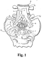
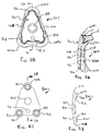
- FIG. 1 there is a diagrammatic representation of the lumbo-sacral region viewed anteriorly.
- FIG 1 shows the last lumbar vertebrae L4, L5 and the first sacral vertebrae S1.
- L4, L5 and S1 are each separated by discs D.
- the main blood vessels present in this region are also shown, namely the vena cava 1, which divides at L5 into the right iliac vein 2 and the left iliac vein 3, and the aorta 4 which divides at L5 into the right iliac artery 5 and the left iliac artery 6.
- the space available in the region between the left iliac vein 3 and right iliac artery 5 makes it difficult to secure a conventional plate having appropriate load carrying capabilities to the L5-S1 junction from an anterior approach.
- the plate 7 has a generally triangular shape in order to adapt to the space available for its implantation. Holes 8, 9, 10 are provided in the plate 7 to permit its fixation by means of screws 11, 12, 13 penetrating into the vertebrae L5 and S 1.
- a first hole 8 is formed near the upper vertex of plate 7 in an upper node 8a.
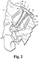
- Upper node 8a is intended to be placed adjacent vertebra L5 so that screw 11 penetrates into L5 adjacent its lower margin or edge 14, as is illustrated in FIG 2 .
- the other two holes 9, 10 are formed near the lower vertices of plate 7 in lower nodes 9a and 10a, respectively.
- Lower nodes 9a and 10a are intended to be placed adjacent vertebra S1 so that screws 12, 13 penetrate into S1 adjacent its upper margin or edge 15, as can be seen in FIG. 2 .
- the vertices of plate 7 are rounded to minimize trauma to adjacent tissue.
- screws 11, 12, and 13 are cancellous bone screws. It is further contemplates that screws 11, 12, and 13 can be any type of bone engaging fastener known in the art.
- the underside of the heads of screws 11, 12, and 13 can be rounded above the smooth shank portions of the screws received in the holes 8,9, and 10. The rounded screw heads allow the screws to become well seated in a curved seating surface formed in plate 7 around holes 8,9, and 10, thus permitting some angulation of the screws relative to the plate 7 as the screws are installed and tightened in place.
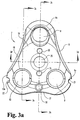
- FIGs. 3a-3d show plate 7 in further detail. As illustrated edges 16, 17, 18 of plate 7 are concave to minimize the lateral and caudal extent of plate 7 between nodes 8a, 9a and 10a. Plate 7 can have a shape between edges 16, 17, and 18 that has a slightly concave curvature on its posterior or lower face 23 in order to better adapt to the anatomy of the spinal column and also a slightly convex curvature along anterior or upper face 19 to minimize anterior protrusion.
- Hole 8 for implantation of screw 11 in L5 is configured to give screw 11 a significant inclination at an angle a relative to the direction perpendicular to anterior face 19 of plate 7.
- Holes 9, 10 for implantation of the screws 12, 13 in S1 are configured to give screws 12, 13 a substantially perpendicular orientation relative to the anterior face 19 of the plate 7.
- screws 12, 13 can be provided with a head having a spherical lower bearing surface so that screws 12 and 13 can assume any one of multiple angular orientations with anterior face 19.
- Plate 7 also includes near its lower edge 17 an opening 20 and near its lower nodes 9a and 10a indents 21 and 22, respectively. Opening 20 and indents 21,22 are intended to allow the plate 7 to be gripped by means of a tool adapted for this purpose, it being understood that hole 20 and indents 21 and 22 constitute only one particular example of such means which can cooperate with a gripping tool. Examples of such a tool will be described below.
- Posterior face 23 of plate 7 is intended to be directed towards the vertebrae.
- Posterior face 23 has a protrusion 24 extending along at least part or substantially all of its width.
- Protrusion 24 has an upper face 25 that is positioned and configured to bear against the lower lip of the anterior margin 14 of the lower endplate of L5, as can be seen in FIG. 2 .
- the oblique orientation of screw 11 tends to press protrusion 24 against L5, which strengthens the hold of plate 7 on L5 and resists any pivoting effect of plate 7 about screw 11 that may result upon lateral flexion of the spine.
- plate 7 also includes protrusions 26, 27 on its posterior face 23 in the area of lower nodes 9a, 10a, along the edges of plate 7.
- Protrusions 26, 27 are placed along S1 and bear against the anterior face of S1 adjacent margin 15, as can be seen in FIG. 2 , so as to help hold plate 7 in place.
- the anchoring of plate 7 on L5 can also be complemented by a ridge-shaped upper lip 28 ( FIGs. 3b and 3c ), or by one or more points 734 ( FIG. 23 ), formed adjacent edges 16, 18 and extending from posterior face 23 of the plate 7 in the region of upper node 8a in the area of its contact with the anterior face of L5.
- Plate 7 also includes a central opening 29 intended to permit insertion and securement of a retaining element for blocking screws 11, 12, 13 inserted through holes 8, 9 and 10, respectively.
- Plate 7 includes two openings 30, 31 cooperating with the retaining element. The function of the retaining element is to prevent screws 11, 12, 13 from tending to escape from their receiving seat after they have been tightened onto plate 7.
- FIG. 5 shows a plate 7 identical to that in FIG. 3 , equipped with a first example of a retaining element 32.
- Retaining element 32 has a circular or substantially circular shape, the diameter of which allows retaining element 32 partially covers holes 8,9,10 after screws 11,12,13 are inserted.
- Retaining element 32 also shown in FIG. 6 , includes a central opening 33 and two openings 34, 35 situated on either side of central opening 33. Openings 34, 35 correspond in location to openings 30, 31 of plate 7.
- Retaining element 32 includes a lower face 36 that includes extending therefrom a series of elastic tabs 37 distributed about central opening 33. It is contemplated that at least two or more tabs 37 are provided. The lower end of each tab 37 includes a beveled end 38 and a bearing surface 40.
- retaining element 32 can be put into place on plate 7 in the following way. Using a suitable tool that includes two rods penetrating openings 34, 35 of retaining element 32, retaining element 32 is brought into position toward plate 7, and the ends of the rods are introduced into openings 30,31 of plate 7. Retaining element plate 32 is then pushed against plate 7 so as to introduce elastic tabs 37 into central opening 29 of plate 7. Beveled ends 38 facilitate this introduction and deflect tabs 37 inwardly toward one another during this introduction. Tabs 37 are thus fitted in central opening 29 of plate 7 and prevent retaining element 32 from becoming dislodged from plate 7. A bearing surface 39 ( FIG.
- Retaining element 32 is formed in central opening 29 of plate 7 to cooperate with bearing surface 40 formed on beveled end 38 of each tab 37.
- Retaining element 32 can thus be installed by clipping it onto plate 7, and can be dislodged therefrom using a suitable tool that can pry tabs 37 from hole 29. It should be understood that other techniques for positioning retaining element 32 on plate 7 are also contemplated, including simply manually placing tabs 37 in hole 29.
- FIG. 4 Another embodiment of the plate of the present invention is provided in FIG. 4 .
- Plate 107 is generally identical to plate 7 discussed above except as otherwise noted below.
- Plate 107 includes holes 109,110 that have an oblong shape so as to give the surgeon more freedom for the location of implantation of screws 12, 13 in S1.
- Oblong holes 109,110 further allow plate 107 to adapt to the postoperative changes in the morphology of the patient.
- hole 108 that receives screw 11 implanted in L5 has a shape exactly adapted to that of the head of screw 11 and prohibits any relative displacement between plate 107 and screw 11 at this level to provide good stability for the implanted plate 107
- FIGs. 7a and 7b Another embodiment retaining element is shown in FIGs. 7a and 7b .
- Retaining element 132 is not circular here but has on its periphery three cutouts 142,143,144 that form flange like projections 142a, 143a and 144a.
- retaining element 132 includes a lower face 136, a central opening 133, and elastic tabs 137 about central opening 133 with beveled ends 138 and bearing surfaces 140.
- three openings 145, 146,147 are formed on retaining element 132, offset 120 relative to one another about central opening 133.
- a U-shaped opening 148 is also formed in order to define an elastic tongue 149 that lifts when a force is exerted on its posterior face 150.
- the end of the tongue 149 has a stud 151 on its posterior face.
- Retaining element 132 is used as follows. Referring to FIGs. 8a and 8b , retaining element 132 can be placed on plate 107 before screw insertion. Retaining element 132 is initially placed on plate 107 so that cutouts 142,143,144 leave holes 108,109,110 of plate 107 entirely exposed, as shown in FIG. 8a , permitting insertion and tightening of screws 11, 12, 13 upon positioning of plate 107 on the vertebrae. The positions and dimensions of cutouts 142,143,144 are chosen accordingly. With retaining element 132 in this position, stud 151 of tongue 150 is engaged in a receiving seat 131 ( FIG. 4 ) formed on anterior face 119 of plate 107.
- Plate 107 is then put into place and screws 11, 12, 13 are tightened.
- a suitable tool is then inserted in one or more of openings 145, 146, 147 of retaining element 132, and retaining element 132 is turned 180° with the aid of this tool.
- stud 151 is released from its seat and permits rotation of retaining element 132. Consequently, flanged portions 142a, 143a, 144a of retaining element 132 partially cover holes 108,109,110 as shown in FIG. 8b .
- Retaining element 132 thus prevents screws 11, 12, 13 from backing out beyond anterior face 119. Retaining element 132 is held in this position by virtue of the engagement of stud 151 in a receiving seat 130 ( FIG. 4 .)
- the pre-fitting of retaining element 132 on plate 107 prior to positioning plate 107 on the vertebrae of the patient eliminates the fiddle factor for the surgeon.
- Plate 107 of the osteosynthesis device in FIG. 8 has oblong holes 109, 110, but it is understood that retaining element 132 can also be used on plate 7 which has circular holes 9, 10.
- retaining element 132 can also be used on plate 7 which has circular holes 9, 10.
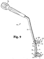
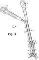
- FIGs. 9-11 An instrument designed for positioning the plates and screws of the present invention is shown in FIGs. 9-11 .
- Instrument 50 will be described with respect to plate 7, it being understood that instrument 50 has application with the other plate embodiments described herein.
- Instrument 50 includes a plate holding portion 52 which matches the shape of lower edge 17 of plate 7.
- Holding portion 52 includes studs (not shown) that are inserted into indents 21, 22. It is further contemplate that holding portion 52 and plate 7 can be provided with any other means of establishing a defined relative position therebetween.
- Instrument 50 further includes a shaft 53 which is bent and has a grip 54 at its proximal end to allow the surgeon to manipulate instrument 50 and plate 7.
- Shaft 53 has adjacent its distal end a distal portion 55 perpendicular to anterior surface 19 that supports holding portion 52.
- instrument 50 further includes a rod 56 extending through the hollow distal portion 55 of shaft 53.
- Rod 56 can be provided with threads and held on shaft 53 by a corresponding thread on an inner wall surface of shaft 53.
- the distal end of rod 56 lodges in opening 20 of plate 7.
- the inner wall surface of opening 20 can include a thread corresponding to a thread on the lower end of rod 56.
- the proximal end of rod 56 opens to the outside of shaft 53 and has a recess 57 for insertion of a screwdriver. Tightening and loosening rod 56 makes it possible for plate 7 and holding portion 52 to be connected and disconnected.
- Instrument 50 also includes a tube 58 which can pass through shaft 53 and is connected to it.
- Tube 58 has an inner passage that allows a rod 59 to be inserted therein and held in position in its internal space.
- Rod 59 includes at its lower end a point 60 which bears on or embeds in vertebra S1 upon positioning of plate 7 thereon.
- Instrument 50 further includes a support 61 attached to shaft 53 and arranged substantially horizontally.
- Support 61 includes a lateral arm 61 a extending to a guide member 61b that includes three guiding portions 62, 63, 64.
- First guiding portion 62 is formed on the side of guide member 61b adjacent shaft 53 and second and third guiding portions 63 and 64 are formed on the side of guide member 61 opposite shaft 53.
- plate 7 is fixed on holding portion 52 as described above.
- the surgeon then positions plate 7 on L5 and S1 at the desired site.
- Plate 7 can be held at the desired site by penetrating point 60 of rod 59 into S1.
- Pusher 65 as shown in FIG. 10 , is also used to firmly seat plate 7 on L5 and S1.
- Pusher 65 is a shaft which has at its proximal end a grip 66 and at its distal end a bulb 67 which can lodge in hole 8 of plate 7.
- Bulb 67 could also lodge in a depression or a hole provided in plate 7 specially adapted for this purpose.
- Bulb 67 can be replaced by any other means capable of ensuring its function of maintaining the position of pusher 65 bearing on plate 7.
- Drill rod 68 includes at a proximal end a grip 69 and at a distal end a bit 70 capable of drilling a hole in a vertebra to receive a screw.
- drill rod 68 is guided through hole 8 of plate 7, and applied against guiding portion 62 of support 61. The position of support 61 and the shape of guiding portion 62 are determined in such a way that the angle of penetration of the drill tip in L5 corresponds to the desired angle of penetration of screw 11.
- Drill rod 68 is then guided through hole 9 and guiding portion 63 of support 61, and through hole 10 and guiding portion 64 of support 61 to drill holes in S1.
- screws 11, 12, 13 are inserted in the holes which have just been drilled and are tightened by means of a conventional screwdriver, which can also be applied against support 61 in a manner similar to what was done for drill rod 68.
- Plate 7 is then disconnected from holding portion 52 by loosening rod 56. The procedure is completed by putting into place a retaining element to block screws 11, 12, 13, if such a retaining element were provided.
- holding portion 52 can be detachable from shaft 53 to allow the use different sizes of plate holding portions 52.
- Various holding portions 52 can be provided that are based on various external dimensions of different sized plates 7. Likewise, for the optimum choice of the points of penetration and the values of the angles of penetration of screws 11, 12, 13, the position and orientation of support 61 and its guiding portions can be determined and adjusted by the surgeon before and during the procedure.
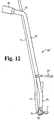
- FIG. 12 Another example of instrument 50 is shown in FIG. 12 and designated as 50'.
- the elements of instrument 50' common to instrument 50 are designated therein by the same reference numbers.
- tube 58 and rod 59 are replaced by a flexible rod 71 arrranged along shaft 53 and passing through its proximal end via a hole 72.
- a rigid rod 73 At the distal end of flexible rod 71 there is a rigid rod 73 which ends in a bearing surface 74 that will rest on S1 upon positioning of plate 7 at a suitable angle therewith. Flexing of rod 71 provides an indication to the surgeon when such contact between bearing surface 74 and S1 is made.
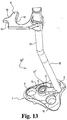
- instrument 50 includes a plate holding portion 52" that includes a foot 72 having a hole 73 therethrough.
- a fastener 75 extends through hole 73 and engages foot 72 to hole 29 of plate 7.
- Foot 72 can include a stud (not shown) extending downwardly therefrom that is positionable in hole 20 to prevent rotation of plate 7 about fastener 75.
- plate 7 need not include indents 21, 22, although provision of the same is not precluded.
- Plate 207 is identical to plates 7, 107 except with respect to its retaining element 232, and that plate 207 does not include indents for coupling to a plate holder, although the provision of such indents is not precluded.
- Plate 207 includes upper hole 208 extending through upper node 208a, first lower hole 209 extending through first lower node 209a, and second lower hole 210 extending through second lower node 210a.
- Plate 207 includes edges 216, 217, 218 extending between anterior face 212 and posterior face 214.
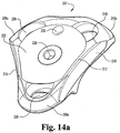
- a retaining element 232 shown in further detail in FIGs. 15a-15b , is secured to anterior face 212 of plate 207 and partially overlaps holes 208,209,210 when screws 11, 12 and 13 are positioned therein.
- Retaining element 232 is secured to plate 207 by a locking fastener 230 that threadingly engages a central hole 229 of plate 207.
- Retaining element 232 has a generally triangular shape with rounded apices that generally match the outer edge profile of plate 207.
- Retaining element 232 can include a hole 235 that can be used to assist in placing locking element 232 to its proper positioning on anterior face 212 or to hold retaining element 232 in position as locking fastener 230 is threaded into hole 229.
- Locking fastener 230 engages a central hole 238 of retaining element 232 and contacts lip 239 extending therearound to hold it against anterior face 212. As shown in FIG.
- locking fastener 230 also extends through hole 229 to posterior face 214.
- Hole 229 has inwardly biased tangs 236 extending therearound at its lower opening, which can be recessed with respect to posterior face 214. Tangs 236 clamp onto locking fastener 230 and prevent it from unthreading.
- retaining element 232 can be provisionally fastened to plate 207 with locking fastener 230 threaded partially into hole 229 before placement of plate 207 on the vertebrae. In this manner, retaining element 232 is rotatable with respect to anterior face 212, and can oriented such that holes 208, 209, and 210 are not blocked thereby. After screws 11, 12 and 13 are inserted to secure plate 207 to the vertebrae, retaining element 232 can be oriented to its FIG. 14a position and locking fastener 230 advanced in hole 229 to engage tangs 236.
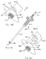
- FIGs. 16a-16c there in shown retaining element 232 captured on the distal end of a retaining element attachment instrument 800. Attachment instrument 800 prevents retaining element 232 from rotating relative to plate 207 as it is attached thereto.
- Attachment instrument 800 includes a proximal handle 802, an outer shaft 804 extending distally from handle 802, and an inner member 806 rotatably received in outer shaft 804.
- inner member 806 is threadingly engaged in outer shaft 804.
- Inner member 806 includes a distal end 808 extending from outer shaft 804 configured to engage the tool recess in the head of locking fastener 230. It is contemplated that the head of locking fastener 230 can be provisionally captured on distal end 808 to assist in inserting retaining element 230 into the patient.
- Inner member 806 includes a proximal end 810 having a rectangular head or the like for engaging a tool for application of a rotary force to inner member 806 while outer shaft 804 is held stationary with handle 802.
- Outer shaft 804 includes a distal foot 812 extending laterally from outer shaft 804 and an extension 814 extending distally from foot 812.
- Extension 814 can be in the form of a rod or shaft sized to engage a receptacle in retaining element 232, such as hole 235 through retaining element 232, as shown in Figs. 16a and 16b . With retaining element 232 captured on locking fastener 230, and inner member 806 engaging locking fastener 230, extension 814 extends through hole 235 of retaining element 232.
- plate 207 is positioned on the L5 and S 1 vertebrae and secured thereto with bone screws using instrument 50" as discussed above. With instrument 50" positioning plate 207 and guiding bone screw placement, retaining element 230 cannot be secured to plate 207 until instrument 50" is removed. With the plate secured to the L5 and S1 vertebrae, instrument 50" is removed from plate 207 for attachment of retaining element 232 with attachment instrument 800.
- Retaining element 232 and locking fastener 230 are positioned on the distal end of attachment instrument 800 as shown in FIGs. 16a and 16b .
- Retaining element 232 is oriented with respect to plate 207 so that each of the corners of retaining element 232 is positioned over respective ones of the plate holes. In this orientation retaining element 232 is inserted in the patient to plate 207.
- the distal end of extension 814 is inserted at least partially into a receptacle in plate 207, such as hole 220, and the distal end of locking fastener 230 is positioned at the anterior surface entrance of hole 229 of plate 207.
- Extension 814 and locking fastener 230 maintain the desired orientation of retaining element 232 and prevent retaining element 232 from rotating relative to plate 207 as retaining element 232 is secured thereto with locking fastener 230.
- inner member 806 As inner member 806 is rotated relative to outer shaft 804 to thread locking fastener 230 into hole 229, inner member 806 distally advances relative to outer shaft 804. As locking fastener 230 is threaded into hole 229, retaining element 232 advances along extension 814 until retaining element 232 is secured against the upper surface of plate 207 with locking fastener 230.
- Plate 407 is identical to plates 7,107 except with respect to the configuration of the retaining elements and their attachment to plate 407, and also in that plate 407 does not include indents for coupling to a plate holder, although the provision of such indents is not precluded.
- Plate 407 includes edges 416,417,418 extending between an anterior face 412 and a posterior face 414. Plate 407 can further include upper protrusion 432 along posterior face 414 for contacting the lower margin of L5.
- Plate 407 further includes a central hole 436 and a lower instrument engaging hole 438 that can be used to engage an insertion instrument.
- Plate 407 includes an upper node 420a, a first lower node 420b and a second lower node 420c each having a screw hole 422a, 422b, 422c, respectively, formed therethrough.
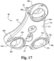
- Upper retaining element 424a is connected with anterior face 412 of plate 407 by a connecting element 426a that is formed as an integral unit with plate 407 and upper retaining element 424a.
- a gap 430a is formed between upper retaining element 424a and anterior face 412.
- Upper retaining element 424a extends at least partially around upper hole 422a and, in its FIG. 17 position, allows entry of a screw 11 through upper hole 422a for attachment to L5.
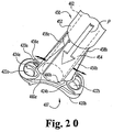
- upper retaining element 424a After screw 11 is seated in upper hole 422a, upper retaining element 424a can be bent or deformed from its first form of FIG. 17 to a second form shown in FIG. 20 . In its second form upper retaining element 424a extends over upper hole 422a and blocks screw 11 if it were to unseat from upper hole 422a and backout from plate 407.
- first and second lower retaining elements 424b, 424c associated with first lower node 420b and second lower node 420c, respectively.
- First and second lower retaining elements 424b, 424c are connected with anterior face 412 of plate 407 by connecting elements 426b, 426c, respectively, that are formed as an integral unit with plate 407 and first and second lower retaining elements 424b, 424c.
- Gaps 430b, 430c are formed between each first and second lower retaining element 424b, 424c, respectively, and anterior face 412.
- Each of the first and second lower retaining elements 424b, 424c extends at least partially around a corresponding one of the first and second lower holes 422b, 422c. In their FIG.
- first and second lower retaining elements 424b, 424c allow entry of screws 12, 13 through first and second lower holes 422b, 422c for attachment to S1.
- first and second lower retaining elements 424b, 424c are deformed or bent by, for example, applying a bending force, from their first form of FIG. 17 to a second form shown in FIG. 20 .
- first and second lower retaining elements 424b, 424c each extend over respective ones of first and second lower holes 422b, 422c and block a corresponding one of the screws 12,13 if one were to unseat from its hole and backout from plate 407.
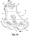
- Plate 407 also provides an alternate arrangement for posterior protrusion 432 intended to contact L5. As shown in FIG. 19 , protrusion 432 is intercepted by hole 422a and is thus not continuous along the width of plate 407. In contrast, protrusion 24 of plate 7 is situated below hole 8 and is continuous along the width of plate 7. It should be understood, however, that the location of the L5 posterior protrusion for the plates described herein can be varied based on patient anatomy and either of the above locations for the L5 posterior protrusion can be provided with any of the plate embodiments described herein.
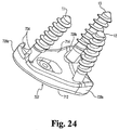
- a forming tool 450 that is operable to simultaneously apply a bending force to retaining elements 424a, 424b, 424c to move these retaining elements from their first form to their second form overlapping the adjacent plate hole.
- Tool 450 has an outer shaft 452 coupled to a distal working end 454.
- Distal working end 454 includes a first forming member 456a positionable adjacent upper retaining element 424a, a second forming member 456b positionable adjacent first lower retaining element 424b, and a third forming member (not shown) positionable adjacent second lower retaining element 424c when tool 450 is mounted on central hole 436 of plate 407.
- the forming members 456a, 456b are wedge shaped and are pivotally coupled to working end 454 at upper ends 458a, 458b and their opposite thicker lower ends 460a, 460b are normally biased towards the center of shaft 452.
- An inner actuator 462 housed in outer shaft 452 and working end 454 is movable with respect thereto in the direction of arrow P.
- Actuator 463 slides distally along the wedge-shaped forming members and pivots their lower ends about their respective upper ends and away from the center of tool 450 into contact with the adjacent retaining element.
- Tool 450 is representative of one type of instrument that can be used to bend or adjust the formable retaining elements from their first form to their second form.
- Other instruments and techniques are also contemplated.
- the retaining elements can be individually bent or adjusted by a tool inserted into the gap along the retaining element and manipulated therein to apply a bending force.
- the retaining elements can also be made from a shape memory alloy and temperature applied thereto in order to form the retaining element from their first form to their second form
- Plate 507 is identical to plate 407 except with respect to the configuration of the retaining elements and their attachment to plate 507.
- Plate 507 includes an upper node 520a, a first lower node 520b and a second lower node 520c each having a screw hole formed therethrough.
- a base member 526 is connected to or formed as an integral unit with plate 507 and extends from its anterior face 512.
- Base member 526 has an upper retaining element 524a adjacent upper hole 522a, a first lower retaining element 524b adjacent first lower hole 522b, and a second lower retaining element 524c adjacent second lower hole 522c.
- Gaps 530a, 530b, and 530c are formed between base member 526 and respective ones of the retaining elements 524a, 524b and 524c.
- Retaining elements 524a, 524b and 524c are illustrated in FIG. 21 in their first form allowing screw insertion into the adjacent holes.
- retaining elements 524a, 524b and 524c can be bent or otherwise moved into a second form after screw insertion wherein the retaining elements extend over the holes of plate 507 and prevent screw backout.
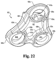
- Plate 607 is identical to plate 407 except with respect to the configuration of the retaining elements and their attachment to plate 607.
- Plate 607 includes an upper node 620a, a first lower node 620b and a second lower node 620c each having a screw hole formed therethrough.
- Plate 607 includes a wall 626 around its perimeter and around holes 622a, 622b, 622c. Wall 626 forms a central opening 627 in the middle of plate 607, and wall 626 separates central opening 627 and holes 622a, 622b, and 622c.
- Central opening 627 enables visualization of an implant I in the disc space and accommodates insertion of a forming tool, such as tool 450 discussed above, alongside upper retaining element 624a adjacent upper hole 622a, first lower retaining element 624b adjacent first lower hole 622b, and second lower retaining element 624c adjacent second lower hole 622c.
- Gaps 630a, 630b, and 630c are formed between each retaining element 624a, 624b, 624c and wall 626, respectively.
- Retaining elements 624a, 624b and 624c are illustrated in FIG. 22 in their first form allowing screw insertion into the adjacent holes.
- retaining elements 624a, 624b and 624c can be bent or moved to a second form after screw insertion wherein the retaining elements extend over the holes of plate 607 and prevent screw backout.
- cutouts 633a, 633b, and 633c are provided in the recess of the hole adjacent retaining elements 624a, 624b, and 624c, respectively, to receive a forming tool inserted therein, which tool can then be pivoted to bend the adjacent retaining element.
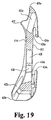
- Plate 707 includes an upper node 720a and first and second lower nodes 720b, 720c. Upper node 720a and lower nodes 720b, 720c each has a hole for receiving a bone screw 11, 12, 13, respectively. Plate 707 further includes an anterior face 712 and an opposite posterior face 714. The edges of plate 707 are not concave between the nodes, but could be provided as such.
- plate 707 is provided with a pair of spikes 734 extending from posterior face 714 at the upper end of plate 707. Spikes 714 are embeddable in the upper vertebral body to which the plate is to be secured, such as L5. Such spikes could likewise be provided with any of the plate embodiments described herein.
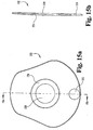
- Plate 707 further includes a retaining element 726 rotatably attached to central hole 736 in the middle of plate 707 by a pin 730.
- Retaining element 726 has an upper apex 724a, first lower apex 724b and second lower apex 724c.
- Retaining element 726 has a first position (not shown) wherein retaining element 726 is positioned with respect to plate 707 so that apices 724a, 724b, 724c are not positioned over the screw holes through the plate nodes 720a, 720b, 720c.
- retaining element 726 is rotated with respect to plate 707 to position apices 724a, 724b, 724c over the screw holes through nodes 720a, 720b, 720c to prevent screw backout.
- a spring blade 728 is initially positioned substantially within a slot 732 formed in retaining element 726. Spring blade 728 can be moved out of slot 732 and into contact with anterior face 712 to prevent further rotation of retaining element 726.
- the orientation between spring blade 728 and anterior face 712 can be such that anterior face 712 biases spring blade 728 upward to provide frictional engagement therebetween causing spring blade 728 to remain in its extended position shown in FIG. 23 .
- the anterior face of the plate could be provided with a seat open on one side and bordered by rails or grooves that allow the retaining element to be slidably inserted therein after the screws have inserted.
- the retaining element could be held in the receiving seat by means of an elastic tongue having formed on its lower face a stud which, upon complete insertion of the retaining element, will penetrate into a receiving seat formed on the anterior surface of the plate.
- Retaining element 900 has a generally triangular shape and is sized to fit on a triangular plate, such as plate 207.
- Retaining element 900 includes an upper node 902, a first lower node 904 and a second lower node 906.
- Retaining element 900 includes a central hole 908 sized to receive a locking fastener, such as locking fastener 230, to secure retaining element 900 in hole 229 of plate 207.
- Hole 908 includes a recess 908a that allows the head of locking fastener 230 to be recessed therein.
- Retaining element 900 also includes an alignment hole 910 alignable with hole 220 of plate 207. Alignment hole 910 is sized to receive an extension of an attachment instrument such as discussed above with respect to attachment instrument 800 and retaining element 232.
- each of the nodes 902, 904, 906 has a profile as shown in FIG. 25 so that each node 902, 904, 906 extends over the screw holes of plate 207 and the heads of the screws positioned therein.
- each node 902, 904, 906 has a semi-circular shape; however, other shapes are also contemplated.
- each node 902, 904, 906 includes an engagement member 912, 914, 916, respectively, extending therefrom into the adjacent screw hole.
- Engagement member 912 included a central protrusion 912a positionable in the tool engaging recess 11a of bone screw 11, as shown in FIG. 26 .
- a recess 912b extends around central protrusion member 912a, and recess 912b is sized to receive the upper surface of the head of bone screw 11.
- Central protrusion 912a is sized to engage bone screw 11 in tool engaging recess 11a so that the sides of tool engaging recess 11a contact central protrusion 912a, fixing bone screw 11 relative to plate 207.
- Engagement members 914, 916 similarly include a central protrusion 914a, 916a and recess 914b, 916b therearound to fix the bone screws in the lower holes of plate 207.
- a bone screw guide such as shown with instrument 50" can be used to engage the bone screws through the plate holes so that the heads of the bone screws are properly positioned relative to plate 207 for engagement with engagement members 912, 914, 916. With the heads of the bone screws engaged by retaining element 900, the bone screws are fixed relative to plate 207.
- Engagement members 912, 914 and 916 are received in the adjacent plate holes so that retaining element 900 can lie flush against the upper surface of plate 207, preventing tissue migration between retaining element 900 and the upper surface of plate 207.
- retaining element 900 extends above the upper surface of plate 207 and includes a thickness that provides sufficient stiffness to retaining element 900 to resisting bending forces and ensure positive fixation of the bone screws should they back out from the vertebra in which they are engaged.
- plates described herein can be provided in a kit with one or more retaining elements and instruments for inserting the plate and retaining element.
- plate 207 can be provided with the requisite bone screws and insertion instrument, such as instrument 50".
- a pair of retaining elements can be provided to give the surgeon flexibility in selecting the desired means for securing plate 207 to the L5/S1 vertebrae.
- retaining element 232 and locking fastener 230 when secured to plate 207, allow the bone screws to pivot and compressive force to be maintained on the graft, implant or other device between the L5 and S1 vertebrae.
- Retaining element 900 and locking fastener 230 when secured to plate 207, fix the bone screws relative to plate 207 maintaining the spacing between the L5 and S 1 vertebrae.
- Clippable retaining elements either pre-fitted or not pre-fitted, are advantageous since the retaining element can secured to the plate easily and quickly. The only manipulations by the surgeon required by clippable retaining elements that are not pre-fitted is to move the retaining element in a direction perpendicular to the plate in the space which corresponds to that which was necessary to form anyway for positioning the plate on the spinal column. Use of sliding elements is also contemplated, which necessitate the formation of an additional space to accommodate sliding insertion of the retaining element if not pre-loaded on the plate.
- the present invention also contemplates retaining elements secured by a threaded fastener and can either be reloaded on the plate or not preloaded on the plate. It should be understood that the present invention contemplates the use of any of the retaining element embodiments described herein with any of the plate embodiments described herein.
- Examples of material which may be employed in fabrication of the plates and retaining elements of the present invention can be made from any biocompatible non-resorbable material, such as titanium, stainless steel, shape memory alloys, and combinations thereof. Resorbable materials are also contemplated.
- the body of the plate can be made from titanium, and the retaining elements made from a shape memory alloy that is formable from the first form allowing screw insertion to the second form for blocking the inserted screws.
- the retaining elements can be made from a material less resistant to bending forces than the plate body, which would allow the retaining elements to be more easily bent by the surgeon.
- the plate assembly of the present invention may also be used in combination with various types of implants I ( FIG. 2 ).
- implants include interbody spacers, fusion device, and bone graft materials that are placed in disc space D.
- Further examples of such devices include bone dowels, push-in cages, screw-in cages, tapered cages, cages filled with bone graft and/or graft substitute material or other types of devices suitable for such fusion applications.
Landscapes
- Health & Medical Sciences (AREA)
- Orthopedic Medicine & Surgery (AREA)
- Surgery (AREA)
- Life Sciences & Earth Sciences (AREA)
- Medical Informatics (AREA)
- Molecular Biology (AREA)
- Veterinary Medicine (AREA)
- Engineering & Computer Science (AREA)
- Biomedical Technology (AREA)
- Heart & Thoracic Surgery (AREA)
- Public Health (AREA)
- Nuclear Medicine, Radiotherapy & Molecular Imaging (AREA)
- Animal Behavior & Ethology (AREA)
- General Health & Medical Sciences (AREA)
- Neurology (AREA)
- Dentistry (AREA)
- Oral & Maxillofacial Surgery (AREA)
- Neurosurgery (AREA)
- Prostheses (AREA)
- Surgical Instruments (AREA)
Applications Claiming Priority (5)
| Application Number | Priority Date | Filing Date | Title |
|---|---|---|---|
| US993860 | 1992-12-21 | ||
| FR0104728 | 2001-04-06 | ||
| FR0104728A FR2823096B1 (fr) | 2001-04-06 | 2001-04-06 | Plaque pour dispositif d'osteosynthese des vertebres l5 et s1, dispositif d'osteosynthese incluant une telle plaque, et instrument pour la pose d'une telle plaque |
| US09/993,860 US6793658B2 (en) | 2001-04-06 | 2001-11-06 | Anterior plating system and method |
| PCT/IB2002/001105 WO2002080791A1 (en) | 2001-04-06 | 2002-04-05 | Anterior plating system and method |
Publications (2)
| Publication Number | Publication Date |
|---|---|
| EP1372504A1 EP1372504A1 (en) | 2004-01-02 |
| EP1372504B1 true EP1372504B1 (en) | 2016-08-31 |
Family
ID=26212961
Family Applications (1)
| Application Number | Title | Priority Date | Filing Date |
|---|---|---|---|
| EP02720342.1A Expired - Lifetime EP1372504B1 (en) | 2001-04-06 | 2002-04-05 | Anterior spinal plating system |
Country Status (5)
| Country | Link |
|---|---|
| EP (1) | EP1372504B1 (enExample) |
| JP (1) | JP4234440B2 (enExample) |
| AU (1) | AU2002251408B2 (enExample) |
| CA (1) | CA2442967A1 (enExample) |
| WO (1) | WO2002080791A1 (enExample) |
Families Citing this family (15)
| Publication number | Priority date | Publication date | Assignee | Title |
|---|---|---|---|---|
| US6740088B1 (en) | 2000-10-25 | 2004-05-25 | Sdgi Holdings, Inc. | Anterior lumbar plate and method |
| US6989012B2 (en) | 2002-07-16 | 2006-01-24 | Sdgi Holdings, Inc. | Plating system for stabilizing a bony segment |
| US7625378B2 (en) | 2002-09-30 | 2009-12-01 | Warsaw Orthopedic, Inc. | Devices and methods for securing a bone plate to a bony segment |
| US7731721B2 (en) | 2003-07-16 | 2010-06-08 | Synthes Usa, Llc | Plating system with multiple function drill guide |
| CA2533908A1 (en) | 2003-08-01 | 2005-02-10 | Hfsc Company | Drill guide assembly for a bone fixation device |
| US7357804B2 (en) | 2003-08-13 | 2008-04-15 | Synthes (U.S.A.) | Quick-release drill-guide assembly for bone-plate |
| US7909860B2 (en) | 2003-09-03 | 2011-03-22 | Synthes Usa, Llc | Bone plate with captive clips |
| US20050049595A1 (en) | 2003-09-03 | 2005-03-03 | Suh Sean S. | Track-plate carriage system |
| WO2008064211A1 (en) * | 2006-11-21 | 2008-05-29 | Smith & Nephew, Inc. | Variable angle drill guide |
| US20080249569A1 (en) * | 2007-04-03 | 2008-10-09 | Warsaw Orthopedic, Inc. | Implant Face Plates |
| US11123117B1 (en) | 2011-11-01 | 2021-09-21 | Nuvasive, Inc. | Surgical fixation system and related methods |
| JP2015506756A (ja) * | 2012-01-18 | 2015-03-05 | グローバス メディカル インコーポレイティッド | 連結装置及び連結装置を使用する方法 |
| KR102567560B1 (ko) * | 2021-02-26 | 2023-08-22 | 경북대학교 산학협력단 | 척추 고정 장치 |
| US12502209B2 (en) | 2021-02-26 | 2025-12-23 | Kyungpook National University Industry-Academic Cooperation Foundation | Spine fixing device |
| CN118319422B (zh) * | 2024-04-18 | 2025-06-13 | 北京大学口腔医学院 | 一种截骨重建骨的定位结构及方法 |
Family Cites Families (14)
| Publication number | Priority date | Publication date | Assignee | Title |
|---|---|---|---|---|
| US5127912A (en) | 1990-10-05 | 1992-07-07 | R. Charles Ray | Sacral implant system |
| EP0599766A1 (en) * | 1992-09-07 | 1994-06-01 | José Vicente Barbera Alacreu | Cervical vertebral fusion system |
| US5423826A (en) * | 1993-02-05 | 1995-06-13 | Danek Medical, Inc. | Anterior cervical plate holder/drill guide and method of use |
| US5569250A (en) * | 1994-03-01 | 1996-10-29 | Sarver; David R. | Method and apparatus for securing adjacent bone portions |
| DE4409833A1 (de) * | 1994-03-22 | 1995-10-05 | Biedermann Motech Gmbh | Stabilisierungseinrichtung, insbesondere zur Stabilisierung der Wirbelsäule |
| FR2726755A1 (fr) * | 1994-11-10 | 1996-05-15 | Kehyayan Georges | Dispositif de blocage temporaire de deux parties d'une piece osseuse |
| EP0867149B1 (en) * | 1995-04-25 | 2000-09-27 | Richard P. Jobe | Surgical bone fixation apparatus |
| FR2747034B1 (fr) * | 1996-04-03 | 1998-06-19 | Scient X | Systeme de contention et de fusion intersomatique |
| ATE371412T1 (de) * | 1997-02-11 | 2007-09-15 | Warsaw Orthopedic Inc | Platte und schraube für die vordere halswirbelsäule |
| AU753521B2 (en) * | 1997-10-24 | 2002-10-17 | Robert S. Bray Jr. | Bone plate and bone screw guide mechanism |
| FR2778088B1 (fr) * | 1998-04-30 | 2000-09-08 | Materiel Orthopedique En Abreg | Implant anterieur notamment pour le rachis cervical |
| US6258089B1 (en) * | 1998-05-19 | 2001-07-10 | Alphatec Manufacturing, Inc. | Anterior cervical plate and fixation system |
| FR2784571B1 (fr) * | 1998-10-19 | 2001-02-02 | Scient X | Plaque d'osteosynthese anterieure pour vertebres lombaires ou lombaire/sacree et instrument pour le positionnement d'une telle plaque |
| FR2794963B1 (fr) * | 1999-06-17 | 2001-09-07 | Eurosurgical | Dispositif anti-recul pour implant orthopedique |
-
2002
- 2002-04-05 WO PCT/IB2002/001105 patent/WO2002080791A1/en not_active Ceased
- 2002-04-05 AU AU2002251408A patent/AU2002251408B2/en not_active Ceased
- 2002-04-05 CA CA002442967A patent/CA2442967A1/en not_active Abandoned
- 2002-04-05 JP JP2002578830A patent/JP4234440B2/ja not_active Expired - Fee Related
- 2002-04-05 EP EP02720342.1A patent/EP1372504B1/en not_active Expired - Lifetime
Also Published As
| Publication number | Publication date |
|---|---|
| EP1372504A1 (en) | 2004-01-02 |
| CA2442967A1 (en) | 2002-10-17 |
| WO2002080791A1 (en) | 2002-10-17 |
| JP2005507269A (ja) | 2005-03-17 |
| AU2002251408B2 (en) | 2007-02-15 |
| JP4234440B2 (ja) | 2009-03-04 |
Similar Documents
| Publication | Publication Date | Title |
|---|---|---|
| EP1558156B1 (en) | Anterior plating system | |
| JP4584876B2 (ja) | 固定用組立体 | |
| US20200375751A1 (en) | Vertebral implant, vertebral fastening device of the implant and implant instrumentation | |
| US20190314062A1 (en) | Dynamic Plate With Inserts | |
| AU2004232317B2 (en) | Bone plate stabilization system and method for its use | |
| EP1372504B1 (en) | Anterior spinal plating system | |
| US20050177161A1 (en) | Static anterior cervical plate | |
| US20080140125A1 (en) | Spinal stabilization system and method | |
| AU2002251408A1 (en) | Anterior plating system and method | |
| US9839449B2 (en) | Translational plate and compressor instrument | |
| US20170000528A1 (en) | Facet lamina plate system | |
| WO2008100239A2 (en) | Improved static anterior cervical plate |
Legal Events
| Date | Code | Title | Description |
|---|---|---|---|
| PUAI | Public reference made under article 153(3) epc to a published international application that has entered the european phase |
Free format text: ORIGINAL CODE: 0009012 |
|
| 17P | Request for examination filed |
Effective date: 20030930 |
|
| AK | Designated contracting states |
Kind code of ref document: A1 Designated state(s): AT BE CH CY DE DK ES FI FR GB GR IE IT LI LU MC NL PT SE TR |
|
| AX | Request for extension of the european patent |
Extension state: AL LT LV MK RO SI |
|
| RIN1 | Information on inventor provided before grant (corrected) |
Inventor name: JOSSE, LOIC Inventor name: LEHUEC, JEAN-CHARLES Inventor name: LANGE, ERIC C. Inventor name: LIU, MINGYAN Inventor name: DICKMAN, CURTIS, A. |
|
| RAP1 | Party data changed (applicant data changed or rights of an application transferred) |
Owner name: WARSAW ORTHOPEDIC, INC. |
|
| GRAP | Despatch of communication of intention to grant a patent |
Free format text: ORIGINAL CODE: EPIDOSNIGR1 |
|
| INTG | Intention to grant announced |
Effective date: 20160323 |
|
| GRAS | Grant fee paid |
Free format text: ORIGINAL CODE: EPIDOSNIGR3 |
|
| GRAA | (expected) grant |
Free format text: ORIGINAL CODE: 0009210 |
|
| AK | Designated contracting states |
Kind code of ref document: B1 Designated state(s): AT BE CH CY DE DK ES FI FR GB GR IE IT LI LU MC NL PT SE TR |
|
| REG | Reference to a national code |
Ref country code: CH Ref legal event code: EP Ref country code: GB Ref legal event code: FG4D |
|
| REG | Reference to a national code |
Ref country code: IE Ref legal event code: FG4D |
|
| REG | Reference to a national code |
Ref country code: DE Ref legal event code: R096 Ref document number: 60248304 Country of ref document: DE |
|
| REG | Reference to a national code |
Ref country code: AT Ref legal event code: REF Ref document number: 824254 Country of ref document: AT Kind code of ref document: T Effective date: 20161015 |
|
| REG | Reference to a national code |
Ref country code: NL Ref legal event code: MP Effective date: 20160831 |
|
| REG | Reference to a national code |
Ref country code: AT Ref legal event code: MK05 Ref document number: 824254 Country of ref document: AT Kind code of ref document: T Effective date: 20160831 |
|
| PG25 | Lapsed in a contracting state [announced via postgrant information from national office to epo] |
Ref country code: FI Free format text: LAPSE BECAUSE OF FAILURE TO SUBMIT A TRANSLATION OF THE DESCRIPTION OR TO PAY THE FEE WITHIN THE PRESCRIBED TIME-LIMIT Effective date: 20160831 |
|
| PG25 | Lapsed in a contracting state [announced via postgrant information from national office to epo] |
Ref country code: NL Free format text: LAPSE BECAUSE OF FAILURE TO SUBMIT A TRANSLATION OF THE DESCRIPTION OR TO PAY THE FEE WITHIN THE PRESCRIBED TIME-LIMIT Effective date: 20160831 Ref country code: AT Free format text: LAPSE BECAUSE OF FAILURE TO SUBMIT A TRANSLATION OF THE DESCRIPTION OR TO PAY THE FEE WITHIN THE PRESCRIBED TIME-LIMIT Effective date: 20160831 Ref country code: SE Free format text: LAPSE BECAUSE OF FAILURE TO SUBMIT A TRANSLATION OF THE DESCRIPTION OR TO PAY THE FEE WITHIN THE PRESCRIBED TIME-LIMIT Effective date: 20160831 Ref country code: GR Free format text: LAPSE BECAUSE OF FAILURE TO SUBMIT A TRANSLATION OF THE DESCRIPTION OR TO PAY THE FEE WITHIN THE PRESCRIBED TIME-LIMIT Effective date: 20161201 Ref country code: ES Free format text: LAPSE BECAUSE OF FAILURE TO SUBMIT A TRANSLATION OF THE DESCRIPTION OR TO PAY THE FEE WITHIN THE PRESCRIBED TIME-LIMIT Effective date: 20160831 |
|
| REG | Reference to a national code |
Ref country code: FR Ref legal event code: PLFP Year of fee payment: 16 |
|
| PG25 | Lapsed in a contracting state [announced via postgrant information from national office to epo] |
Ref country code: BE Free format text: LAPSE BECAUSE OF FAILURE TO SUBMIT A TRANSLATION OF THE DESCRIPTION OR TO PAY THE FEE WITHIN THE PRESCRIBED TIME-LIMIT Effective date: 20160831 Ref country code: DK Free format text: LAPSE BECAUSE OF FAILURE TO SUBMIT A TRANSLATION OF THE DESCRIPTION OR TO PAY THE FEE WITHIN THE PRESCRIBED TIME-LIMIT Effective date: 20160831 Ref country code: PT Free format text: LAPSE BECAUSE OF FAILURE TO SUBMIT A TRANSLATION OF THE DESCRIPTION OR TO PAY THE FEE WITHIN THE PRESCRIBED TIME-LIMIT Effective date: 20170102 |
|
| REG | Reference to a national code |
Ref country code: DE Ref legal event code: R097 Ref document number: 60248304 Country of ref document: DE |
|
| PG25 | Lapsed in a contracting state [announced via postgrant information from national office to epo] |
Ref country code: IT Free format text: LAPSE BECAUSE OF FAILURE TO SUBMIT A TRANSLATION OF THE DESCRIPTION OR TO PAY THE FEE WITHIN THE PRESCRIBED TIME-LIMIT Effective date: 20160831 |
|
| PLBE | No opposition filed within time limit |
Free format text: ORIGINAL CODE: 0009261 |
|
| STAA | Information on the status of an ep patent application or granted ep patent |
Free format text: STATUS: NO OPPOSITION FILED WITHIN TIME LIMIT |
|
| 26N | No opposition filed |
Effective date: 20170601 |
|
| REG | Reference to a national code |
Ref country code: CH Ref legal event code: PL |
|
| GBPC | Gb: european patent ceased through non-payment of renewal fee |
Effective date: 20170405 |
|
| REG | Reference to a national code |
Ref country code: IE Ref legal event code: MM4A |
|
| PG25 | Lapsed in a contracting state [announced via postgrant information from national office to epo] |
Ref country code: MC Free format text: LAPSE BECAUSE OF FAILURE TO SUBMIT A TRANSLATION OF THE DESCRIPTION OR TO PAY THE FEE WITHIN THE PRESCRIBED TIME-LIMIT Effective date: 20160831 |
|
| PG25 | Lapsed in a contracting state [announced via postgrant information from national office to epo] |
Ref country code: LI Free format text: LAPSE BECAUSE OF NON-PAYMENT OF DUE FEES Effective date: 20170430 Ref country code: CH Free format text: LAPSE BECAUSE OF NON-PAYMENT OF DUE FEES Effective date: 20170430 Ref country code: LU Free format text: LAPSE BECAUSE OF NON-PAYMENT OF DUE FEES Effective date: 20170405 Ref country code: GB Free format text: LAPSE BECAUSE OF NON-PAYMENT OF DUE FEES Effective date: 20170405 |
|
| REG | Reference to a national code |
Ref country code: FR Ref legal event code: PLFP Year of fee payment: 17 |
|
| PG25 | Lapsed in a contracting state [announced via postgrant information from national office to epo] |
Ref country code: IE Free format text: LAPSE BECAUSE OF NON-PAYMENT OF DUE FEES Effective date: 20170405 |
|
| PGFP | Annual fee paid to national office [announced via postgrant information from national office to epo] |
Ref country code: FR Payment date: 20180322 Year of fee payment: 17 |
|
| PGFP | Annual fee paid to national office [announced via postgrant information from national office to epo] |
Ref country code: DE Payment date: 20180320 Year of fee payment: 17 |
|
| PG25 | Lapsed in a contracting state [announced via postgrant information from national office to epo] |
Ref country code: CY Free format text: LAPSE BECAUSE OF NON-PAYMENT OF DUE FEES Effective date: 20160831 |
|
| REG | Reference to a national code |
Ref country code: DE Ref legal event code: R119 Ref document number: 60248304 Country of ref document: DE |
|
| PG25 | Lapsed in a contracting state [announced via postgrant information from national office to epo] |
Ref country code: DE Free format text: LAPSE BECAUSE OF NON-PAYMENT OF DUE FEES Effective date: 20191101 |
|
| PG25 | Lapsed in a contracting state [announced via postgrant information from national office to epo] |
Ref country code: FR Free format text: LAPSE BECAUSE OF NON-PAYMENT OF DUE FEES Effective date: 20190430 |
|
| PG25 | Lapsed in a contracting state [announced via postgrant information from national office to epo] |
Ref country code: TR Free format text: LAPSE BECAUSE OF FAILURE TO SUBMIT A TRANSLATION OF THE DESCRIPTION OR TO PAY THE FEE WITHIN THE PRESCRIBED TIME-LIMIT Effective date: 20160831 |