EP1372226A1 - Combiné connecteur-interrupteur pour antenne plate - Google Patents
Combiné connecteur-interrupteur pour antenne plate Download PDFInfo
- Publication number
- EP1372226A1 EP1372226A1 EP03290817A EP03290817A EP1372226A1 EP 1372226 A1 EP1372226 A1 EP 1372226A1 EP 03290817 A EP03290817 A EP 03290817A EP 03290817 A EP03290817 A EP 03290817A EP 1372226 A1 EP1372226 A1 EP 1372226A1
- Authority
- EP
- European Patent Office
- Prior art keywords
- circuit
- plug
- antenna
- hole
- ground plane
- Prior art date
- Legal status (The legal status is an assumption and is not a legal conclusion. Google has not performed a legal analysis and makes no representation as to the accuracy of the status listed.)
- Granted
Links
- 239000004020 conductor Substances 0.000 description 4
- 230000005540 biological transmission Effects 0.000 description 2
- 241000446313 Lamella Species 0.000 description 1
- 230000007423 decrease Effects 0.000 description 1
- 238000005259 measurement Methods 0.000 description 1
- 210000000056 organ Anatomy 0.000 description 1
- 230000005855 radiation Effects 0.000 description 1
- 238000011084 recovery Methods 0.000 description 1
- 238000000926 separation method Methods 0.000 description 1
Images

Classifications
-
- H—ELECTRICITY
- H01—ELECTRIC ELEMENTS
- H01R—ELECTRICALLY-CONDUCTIVE CONNECTIONS; STRUCTURAL ASSOCIATIONS OF A PLURALITY OF MUTUALLY-INSULATED ELECTRICAL CONNECTING ELEMENTS; COUPLING DEVICES; CURRENT COLLECTORS
- H01R24/00—Two-part coupling devices, or either of their cooperating parts, characterised by their overall structure
- H01R24/38—Two-part coupling devices, or either of their cooperating parts, characterised by their overall structure having concentrically or coaxially arranged contacts
- H01R24/40—Two-part coupling devices, or either of their cooperating parts, characterised by their overall structure having concentrically or coaxially arranged contacts specially adapted for high frequency
- H01R24/42—Two-part coupling devices, or either of their cooperating parts, characterised by their overall structure having concentrically or coaxially arranged contacts specially adapted for high frequency comprising impedance matching means or electrical components, e.g. filters or switches
- H01R24/46—Two-part coupling devices, or either of their cooperating parts, characterised by their overall structure having concentrically or coaxially arranged contacts specially adapted for high frequency comprising impedance matching means or electrical components, e.g. filters or switches comprising switches
-
- H—ELECTRICITY
- H01—ELECTRIC ELEMENTS
- H01R—ELECTRICALLY-CONDUCTIVE CONNECTIONS; STRUCTURAL ASSOCIATIONS OF A PLURALITY OF MUTUALLY-INSULATED ELECTRICAL CONNECTING ELEMENTS; COUPLING DEVICES; CURRENT COLLECTORS
- H01R2103/00—Two poles
-
- H—ELECTRICITY
- H01—ELECTRIC ELEMENTS
- H01R—ELECTRICALLY-CONDUCTIVE CONNECTIONS; STRUCTURAL ASSOCIATIONS OF A PLURALITY OF MUTUALLY-INSULATED ELECTRICAL CONNECTING ELEMENTS; COUPLING DEVICES; CURRENT COLLECTORS
- H01R24/00—Two-part coupling devices, or either of their cooperating parts, characterised by their overall structure
- H01R24/38—Two-part coupling devices, or either of their cooperating parts, characterised by their overall structure having concentrically or coaxially arranged contacts
- H01R24/40—Two-part coupling devices, or either of their cooperating parts, characterised by their overall structure having concentrically or coaxially arranged contacts specially adapted for high frequency
- H01R24/50—Two-part coupling devices, or either of their cooperating parts, characterised by their overall structure having concentrically or coaxially arranged contacts specially adapted for high frequency mounted on a PCB [Printed Circuit Board]
-
- Y—GENERAL TAGGING OF NEW TECHNOLOGICAL DEVELOPMENTS; GENERAL TAGGING OF CROSS-SECTIONAL TECHNOLOGIES SPANNING OVER SEVERAL SECTIONS OF THE IPC; TECHNICAL SUBJECTS COVERED BY FORMER USPC CROSS-REFERENCE ART COLLECTIONS [XRACs] AND DIGESTS
- Y10—TECHNICAL SUBJECTS COVERED BY FORMER USPC
- Y10S—TECHNICAL SUBJECTS COVERED BY FORMER USPC CROSS-REFERENCE ART COLLECTIONS [XRACs] AND DIGESTS
- Y10S439/00—Electrical connectors
- Y10S439/944—Coaxial connector having circuit-interrupting provision effected by mating or having "dead" contact activated after mating
Definitions
- the present invention relates to devices which combine both a connector and a switch to disconnect an "antenna circuit", in particular of the type “Patch antenna” hereinafter referred to as flat antenna, power supply circuits thereof, while connecting these same circuits to a plug allowing a external connection of these circuits.
- This sheet is for example connected itself to a cable to supply an antenna more efficient than the initial flat antenna.
- Such devices are for example useful for connect a mobile phone to a fixed base.
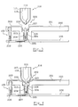
- the flat antenna 101 is fixed on a support 102, as well as the ground plane 103 which completes the antenna to obtain the desired radiation pattern.
- the antenna is supplied by a spring connector 104 and the ground plane by a spring connector 105, from the transmission and / or reception circuits of radio frequency signals which are themselves fixed on a printed circuit board 106.
- the radio frequency signal arrives on this circuit printed by a circuit 107 and grounded by a circuit 108.
- the radio frequency signal is then routed from this circuit 107 to the spring connector 104 by via a switch 109 formed by a strip with spring 110 which can, depending on its position, ensure the continuity between circuit 107 and circuit 111 on which is supported by the spring connector 104.
- Continuity between the lamella 110 and the circuit 111 is provided by a conductive piece 112 fixed in the insulating body 113 of the switch.
- a rod metallic 114 perpendicular to the plane of circuit 106 is fixed on the flexible blade 110.
- the radio frequency signal which arrives via conductor 107, goes through the blade 110, the part 112, the conductor 111 and the spring connector 104 to be finally applied to the flat antenna 101.
- a plug 116 comprising an outer casing 117 and a central conductor 119 forming a core and separate from the conductive outer shell with a layer insulating 118.
- This plug is conical, so that ability to fit into hole 120 in holder 102 to the right of switch 109 and also located at separation level between the flat antenna 101 and the ground plate 103.
- the end of the central conductor 119 of file 116 comes to project at the point of this conical part at the level of a hole made in the outer casing 117.
- the conical part of the casing 117 of the plug is placed in a controlled depression in the upper part of the conductive pot 115 of switch 119, and adapted to the conical shape of the end of the plug.
- the contact is established between the envelope 117 of the plug and the pot 115 of the switch, which establishes the ground connection between circuit 108 and the outer envelope of the plug.
- the invention provides a handset connector-switch to alternately connect a ground circuit respectively to a ground plane or to the external envelope of a plug, and a radio circuit frequency respectively to an antenna circuit or to the core of said plug, this ground plane and this antenna circuit being carried by the same insulating flat support comprising a hole allowing said plug to pass, mainly characterized in that the ground circuit is connected to said ground plane by a first spring connector separate from the switching means of the handset, that the planar support includes a projection hollow cylindrical with an internal cavity opening into said hole, that this hole has a hollow oval periphery adapted to the ogival shape of said plug, that the antenna circuit and the ground plane extend towards the inside of the hole while conforming at said hollow oval periphery, and that the combined further includes a second spring connector placed in said internal cavity and comprising a rod central unit fitted with a flange and pushed in one direction by
- the handset includes a coplanar printed circuit board to the said planar support supporting said ground circuit and said radio frequency circuit; said cylindrical outgrowth coming to rest on the printed circuit board and the second spring connector also coming to bear on the circuit board at the circuit radio frequency by its opposite end to that allowing to establish contact with the file.
- the extension of the antenna circuit inside the hole is enough long to serve as a retainer for said central rod by through the collar carried by this rod Central.
- the device according to the invention also includes a planar antenna 201 and a plane of mass 203 fixed on a support 202, as well as a printed circuit board 106 which has a circuit radio frequency signal 207 and a ground circuit 208.
- Plug 116 intended to connect to this device is identical to that of FIGS. 1 and 2.
- the ground circuit 208 is connected to the ground plane 203 via a spring connector 105, the same way as in figure 1. However this circuit 208 is only connected to the spring connector 105.
- the support 202 includes a projection 213 in cylinder shape perpendicular to the plane of this support, that of the printed circuit board 106, and that antenna and ground plane. This outgrowth is hollow and its axis coincides with that of plug 116 in the position where it is connected to the device.
- the interior cavity of cylinder 213 contains a second spring contactor 204, the base of which is direct contact with circuit 207 receiving the signal radio frequency.
- the upper end of the internal cavity of the cylinder 213 comes to open on the surface of the support 202 by forming a conical cavity 220.
- the conductive sheet forming the flat antenna 201 is stamped in the shape of this conical cavity 220 for come out inside the cylindrical cavity internal of cylinder 213.
- the metallic sheet making up the ground plane 203 is stamped to the shape of the cavity conical 220 to open into this cylindrical cavity internal of cylinder 213.
- the lengths of the 227 parts of the flat antenna on the one hand, and 228 of the ground plane on the other hand, which lead into this interior are such that the end the flat antenna is located closer to the circuit printed 106 as is the end of the ground plane.
- the spring contact 204 comprises, so known, a movable rod 224 which is pushed upwards by a spring 225.
- This rod has at its end upper, slightly lower than this, a flange 226 which is wider than the space between ends 227 and 228 respectively of the flat antenna and the ground plane which open into the internal cavity outgrowth 213.
- the flat antenna 201 is therefore supplied by the spring connector 204 from circuit 207, and the ground plane 203 is connected to ground circuit 208 by through the spring connector 205.
- the plug When the plug is fully inserted in the oval hole 220, it is locked in position connected by mechanical means such as those mentioned above, and the ground contact is then established between the ground plane 203 and the outer envelope 117 of the form through part 228 of the plan mass.
- the flat antenna 201 is itself connected to the outer envelope 117 through its part 227.
- the platform antenna with the ground plane a plane of single mass, enlarged and substantially continuous, which further improves the performance of the assembly.
- the oval hole 220 is much smaller as the oval hole 120 of the prior art, which increases the dimensions of the flat antenna and therefore its efficiency.
Landscapes
- Details Of Aerials (AREA)
- Support Of Aerials (AREA)
- Coupling Device And Connection With Printed Circuit (AREA)
- Waveguide Aerials (AREA)
- Variable-Direction Aerials And Aerial Arrays (AREA)
- Details Of Connecting Devices For Male And Female Coupling (AREA)
Abstract
Description
- Les figures 1 et 2, des vues en coupe d'un dispositif connu, dans deux états respectivement non connecté et connecté ; et
- Les figures 3 et 4, des vues en coupe d'un dispositif selon l'invention, dans les mêmes états non connecté et connecté.
Claims (4)
- Combiné connecteur-interrupteur pour connecter alternativement un circuit de masse (208) respectivement à un plan de masse (203) ou à l'enveloppe externe (117) d'une fiche (116), et un circuit radio fréquence (207) respectivement à un circuit antenne (201) ou à l'âme (119) de ladite fiche, ce plan de masse et ce circuit antenne étant portés par un même support plan isolant (202) comportant un trou (220) permettant de laisser passer ladite fiche (116), caractérisé en ce que :le circuit de masse (208) est connecté audit plan de masse (203) par un premier connecteur à ressort (105) distinct des moyens de commutation du combiné,le support plan comprend une excroissance cylindrique creuse (213) comportant une cavité interne débouchant dans ledit trou (220),ledit trou comporte une périphérie creuse ovale adaptée à la forme ogivale de ladite fiche (116),le circuit antenne et le plan de masse se prolongent vers l'intérieur du trou en étant conformes à ladite périphérie creuse ovale,le combiné comporte en outre un deuxième connecteur à ressort (204) placé dans ladite cavité interne et comprenant une tige centrale (224) munie d'une collerette et poussée dans un sens par un élément ressort (225) pour établir le contact avec le circuit antenne lorsque ladite fiche est enlevée, et pour établir le contact avec ladite âme en coupant le contact avec le circuit antenne lorsque ladite fiche est enfoncée dans le trou en poussant ladite tige dans l'autre sens.
- Combiné selon la revendication 1, caractérisé en ce qu'il comprend une plaque de circuit imprimé (106) coplanaire au dit support plan (202) supportant ledit circuit de masse (208) et ledit circuit radio fréquence (207); ladite excroissance cylindrique (213) venant s'appuyer sur la plaque de circuit imprimé (106) et le deuxième connecteur à ressort (204) venant lui aussi s'appuyer sur la plaque de circuit imprimé (106) au niveau du circuit radio fréquence (207) par son extrémité opposée à celle permettant d'établir le contact avec la fiche (116).
- Combiné selon l'une quelconque des revendications 1 et 2, caractérisé en ce que le prolongement (227) du circuit antenne à l'intérieur du trou (220) est suffisamment long pour servir d'arrêtoir à ladite tige centrale (224) par l'intermédiaire de la collerette (226) portée par cette tige centrale.
- Combiné selon l'une quelconque des revendications 1 à 3, caractérisé en ce que le circuit antenne est de type « patch antenna » dénommée antenne plate.
Applications Claiming Priority (2)
| Application Number | Priority Date | Filing Date | Title |
|---|---|---|---|
| FR0207272 | 2002-06-13 | ||
| FR0207272A FR2841038B1 (fr) | 2002-06-13 | 2002-06-13 | Combine connecteur-interrupteur pour antenne plate |
Publications (2)
| Publication Number | Publication Date |
|---|---|
| EP1372226A1 true EP1372226A1 (fr) | 2003-12-17 |
| EP1372226B1 EP1372226B1 (fr) | 2006-06-07 |
Family
ID=29559158
Family Applications (1)
| Application Number | Title | Priority Date | Filing Date |
|---|---|---|---|
| EP03290817A Expired - Lifetime EP1372226B1 (fr) | 2002-06-13 | 2003-04-01 | Combiné connecteur-interrupteur pour antenne plate |
Country Status (8)
| Country | Link |
|---|---|
| US (1) | US6712628B2 (fr) |
| EP (1) | EP1372226B1 (fr) |
| CN (1) | CN100342584C (fr) |
| AT (1) | ATE329388T1 (fr) |
| DE (1) | DE60305792T2 (fr) |
| ES (1) | ES2266744T3 (fr) |
| FR (1) | FR2841038B1 (fr) |
| PT (1) | PT1372226E (fr) |
Families Citing this family (2)
| Publication number | Priority date | Publication date | Assignee | Title |
|---|---|---|---|---|
| CN102025020B (zh) * | 2009-09-18 | 2014-03-26 | 上海莫仕连接器有限公司 | 移动通讯装置的模块化天线装置 |
| US8628358B2 (en) * | 2010-04-16 | 2014-01-14 | Hon Hai Precision Industry Co., Ltd. | Electrical connector having movable central contact |
Citations (3)
| Publication number | Priority date | Publication date | Assignee | Title |
|---|---|---|---|---|
| GB2307113A (en) * | 1995-11-08 | 1997-05-14 | Itt Ind Ltd | Coaxial connector |
| EP1041680A2 (fr) * | 1999-03-30 | 2000-10-04 | The Whitaker Corporation | Protection contre les décharges électrostatiques pour un connecteur coaxial |
| EP1187267A2 (fr) * | 2000-08-31 | 2002-03-13 | Hirose Electric Co., Ltd. | Connecteur coaxial équipé d'un interrupteur |
Family Cites Families (3)
| Publication number | Priority date | Publication date | Assignee | Title |
|---|---|---|---|---|
| US6224407B1 (en) * | 1997-12-17 | 2001-05-01 | The Whitaker Corporation | Coaxial switch connector assembly |
| TW488116B (en) * | 2000-03-31 | 2002-05-21 | Matsushita Electric Works Ltd | Receptacle for coaxial plug connector |
| US6473045B1 (en) * | 2001-07-09 | 2002-10-29 | Tyco Electronics Corporation | Coaxial connector assembly and antenna assembly having a switching function |
-
2002
- 2002-06-13 FR FR0207272A patent/FR2841038B1/fr not_active Expired - Fee Related
-
2003
- 2003-04-01 ES ES03290817T patent/ES2266744T3/es not_active Expired - Lifetime
- 2003-04-01 DE DE60305792T patent/DE60305792T2/de not_active Expired - Lifetime
- 2003-04-01 EP EP03290817A patent/EP1372226B1/fr not_active Expired - Lifetime
- 2003-04-01 AT AT03290817T patent/ATE329388T1/de not_active IP Right Cessation
- 2003-04-01 PT PT03290817T patent/PT1372226E/pt unknown
- 2003-04-18 CN CNB031106455A patent/CN100342584C/zh not_active Expired - Fee Related
- 2003-05-13 US US10/436,258 patent/US6712628B2/en not_active Expired - Lifetime
Patent Citations (3)
| Publication number | Priority date | Publication date | Assignee | Title |
|---|---|---|---|---|
| GB2307113A (en) * | 1995-11-08 | 1997-05-14 | Itt Ind Ltd | Coaxial connector |
| EP1041680A2 (fr) * | 1999-03-30 | 2000-10-04 | The Whitaker Corporation | Protection contre les décharges électrostatiques pour un connecteur coaxial |
| EP1187267A2 (fr) * | 2000-08-31 | 2002-03-13 | Hirose Electric Co., Ltd. | Connecteur coaxial équipé d'un interrupteur |
Also Published As
| Publication number | Publication date |
|---|---|
| FR2841038A1 (fr) | 2003-12-19 |
| CN1467871A (zh) | 2004-01-14 |
| ES2266744T3 (es) | 2007-03-01 |
| DE60305792D1 (de) | 2006-07-20 |
| CN100342584C (zh) | 2007-10-10 |
| FR2841038B1 (fr) | 2004-08-27 |
| ATE329388T1 (de) | 2006-06-15 |
| EP1372226B1 (fr) | 2006-06-07 |
| US20030232531A1 (en) | 2003-12-18 |
| DE60305792T2 (de) | 2007-06-14 |
| PT1372226E (pt) | 2006-10-31 |
| US6712628B2 (en) | 2004-03-30 |
Similar Documents
| Publication | Publication Date | Title |
|---|---|---|
| CA1055603A (fr) | Systeme de connexion de circuits rf pour postes de radio portatifs | |
| EP1154527B1 (fr) | Dispositif de raccordement d'un câble coaxial à une carte de circuit imprimé | |
| EP1054479A1 (fr) | Dispositif pour relier électriquement une ligne coaxiale à une carte de circuit imprimé | |
| FR2621742A1 (fr) | Antenne pour vehicule | |
| JPH06236785A (ja) | スイッチ付コネクタ | |
| FR2806218A1 (fr) | Connecteur d'entree/sortie du type fiche | |
| EP1592098A3 (fr) | Connecteur coaxial | |
| WO2011144881A1 (fr) | Interface d'antenne pour poste à radiofréquences | |
| FR2694138A1 (fr) | Système d'adaptation entre une fiche d'antenne et un socle d'un radiotéléphone. | |
| EP0678223B1 (fr) | Composant connecteur-commutateur de type coaxial pour hautes frequences | |
| WO1995013637A9 (fr) | Composant connecteur-commutateur de type coaxial pour hautes frequences | |
| EP1589608A1 (fr) | Antenne compacte RF | |
| FR2740912A1 (fr) | Perfectionnements concernant des connecteurs coaxiaux | |
| EP1372226A1 (fr) | Combiné connecteur-interrupteur pour antenne plate | |
| FR2812462A1 (fr) | Appareil de commutation a isolant gazeux de type hybride | |
| FR2733348A1 (fr) | Connecteur interrupteur ou inverseur coaxial miniature a lames de contact actives | |
| CN1227771C (zh) | 组合蜂窝/卫星无线通信装置和方法 | |
| FR2754942A1 (fr) | Systeme antennaire pour poste radiotelephone portatif | |
| EP1378023A1 (fr) | Radiotelephone portatif | |
| EP0833402A1 (fr) | "Appareil de radiotransmission comportant un dispositif d'antenne repliable et dispositif d'antenne pour un tel appareil" | |
| CA2327868A1 (fr) | Interconnexion electrique a alignement automatique | |
| EP1250731A1 (fr) | Element de connecteur electrique coaxial et connecteur electrique coaxial comportant un tel element | |
| EP0821837B1 (fr) | Connecteur interrupteur ou inverseur coaxial miniature a plongeur et lames de contact passives | |
| EP1050921A1 (fr) | Téléphone muni d'une antenne connectée | |
| EP0444567A1 (fr) | Dispositif pour raccorder un câble coaxial à un circuit imprimé, sans préparation du câble |
Legal Events
| Date | Code | Title | Description |
|---|---|---|---|
| PUAI | Public reference made under article 153(3) epc to a published international application that has entered the european phase |
Free format text: ORIGINAL CODE: 0009012 |
|
| AK | Designated contracting states |
Kind code of ref document: A1 Designated state(s): AT BE BG CH CY CZ DE DK EE ES FI FR GB GR HU IE IT LI LU MC NL PT RO SE SI SK TR |
|
| AX | Request for extension of the european patent |
Extension state: AL LT LV MK |
|
| 17P | Request for examination filed |
Effective date: 20040617 |
|
| AKX | Designation fees paid |
Designated state(s): AT BE BG CH CY CZ DE DK EE ES FI FR GB GR HU IE IT LI LU MC NL PT RO SE SI SK TR |
|
| RAP1 | Party data changed (applicant data changed or rights of an application transferred) |
Owner name: TAM HOLDINGS LIMITED |
|
| RAP1 | Party data changed (applicant data changed or rights of an application transferred) |
Owner name: TCL & ALCATEL MOBILE PHONES LIMITED |
|
| GRAP | Despatch of communication of intention to grant a patent |
Free format text: ORIGINAL CODE: EPIDOSNIGR1 |
|
| RTI1 | Title (correction) |
Free format text: SWITCH-CONNECTOR ASSEMBLY FOR FLAT ANTENNA |
|
| GRAS | Grant fee paid |
Free format text: ORIGINAL CODE: EPIDOSNIGR3 |
|
| GRAA | (expected) grant |
Free format text: ORIGINAL CODE: 0009210 |
|
| AK | Designated contracting states |
Kind code of ref document: B1 Designated state(s): AT BE BG CH CY CZ DE DK EE ES FI FR GB GR HU IE IT LI LU MC NL PT RO SE SI SK TR |
|
| PG25 | Lapsed in a contracting state [announced via postgrant information from national office to epo] |
Ref country code: IT Free format text: LAPSE BECAUSE OF FAILURE TO SUBMIT A TRANSLATION OF THE DESCRIPTION OR TO PAY THE FEE WITHIN THE PRESCRIBED TIME-LIMIT;WARNING: LAPSES OF ITALIAN PATENTS WITH EFFECTIVE DATE BEFORE 2007 MAY HAVE OCCURRED AT ANY TIME BEFORE 2007. THE CORRECT EFFECTIVE DATE MAY BE DIFFERENT FROM THE ONE RECORDED. Effective date: 20060607 Ref country code: AT Free format text: LAPSE BECAUSE OF FAILURE TO SUBMIT A TRANSLATION OF THE DESCRIPTION OR TO PAY THE FEE WITHIN THE PRESCRIBED TIME-LIMIT Effective date: 20060607 Ref country code: CZ Free format text: LAPSE BECAUSE OF FAILURE TO SUBMIT A TRANSLATION OF THE DESCRIPTION OR TO PAY THE FEE WITHIN THE PRESCRIBED TIME-LIMIT Effective date: 20060607 Ref country code: SI Free format text: LAPSE BECAUSE OF FAILURE TO SUBMIT A TRANSLATION OF THE DESCRIPTION OR TO PAY THE FEE WITHIN THE PRESCRIBED TIME-LIMIT Effective date: 20060607 Ref country code: NL Free format text: LAPSE BECAUSE OF FAILURE TO SUBMIT A TRANSLATION OF THE DESCRIPTION OR TO PAY THE FEE WITHIN THE PRESCRIBED TIME-LIMIT Effective date: 20060607 Ref country code: SK Free format text: LAPSE BECAUSE OF FAILURE TO SUBMIT A TRANSLATION OF THE DESCRIPTION OR TO PAY THE FEE WITHIN THE PRESCRIBED TIME-LIMIT Effective date: 20060607 Ref country code: RO Free format text: LAPSE BECAUSE OF FAILURE TO SUBMIT A TRANSLATION OF THE DESCRIPTION OR TO PAY THE FEE WITHIN THE PRESCRIBED TIME-LIMIT Effective date: 20060607 |
|
| REG | Reference to a national code |
Ref country code: GB Ref legal event code: FG4D Free format text: NOT ENGLISH |
|
| REG | Reference to a national code |
Ref country code: CH Ref legal event code: EP |
|
| REG | Reference to a national code |
Ref country code: IE Ref legal event code: FG4D Free format text: LANGUAGE OF EP DOCUMENT: FRENCH |
|
| REF | Corresponds to: |
Ref document number: 60305792 Country of ref document: DE Date of ref document: 20060720 Kind code of ref document: P |
|
| PG25 | Lapsed in a contracting state [announced via postgrant information from national office to epo] |
Ref country code: DK Free format text: LAPSE BECAUSE OF FAILURE TO SUBMIT A TRANSLATION OF THE DESCRIPTION OR TO PAY THE FEE WITHIN THE PRESCRIBED TIME-LIMIT Effective date: 20060907 Ref country code: SE Free format text: LAPSE BECAUSE OF FAILURE TO SUBMIT A TRANSLATION OF THE DESCRIPTION OR TO PAY THE FEE WITHIN THE PRESCRIBED TIME-LIMIT Effective date: 20060907 |
|
| GBT | Gb: translation of ep patent filed (gb section 77(6)(a)/1977) |
Effective date: 20060906 |
|
| REG | Reference to a national code |
Ref country code: PT Ref legal event code: SC4A Effective date: 20060906 |
|
| NLV1 | Nl: lapsed or annulled due to failure to fulfill the requirements of art. 29p and 29m of the patents act | ||
| REG | Reference to a national code |
Ref country code: ES Ref legal event code: FG2A Ref document number: 2266744 Country of ref document: ES Kind code of ref document: T3 |
|
| PGFP | Annual fee paid to national office [announced via postgrant information from national office to epo] |
Ref country code: PT Payment date: 20070330 Year of fee payment: 5 |
|
| PLBE | No opposition filed within time limit |
Free format text: ORIGINAL CODE: 0009261 |
|
| STAA | Information on the status of an ep patent application or granted ep patent |
Free format text: STATUS: NO OPPOSITION FILED WITHIN TIME LIMIT |
|
| PGFP | Annual fee paid to national office [announced via postgrant information from national office to epo] |
Ref country code: IE Payment date: 20070420 Year of fee payment: 5 |
|
| 26N | No opposition filed |
Effective date: 20070308 |
|
| REG | Reference to a national code |
Ref country code: CH Ref legal event code: PL |
|
| BERE | Be: lapsed |
Owner name: TCL & ALCATEL MOBILE PHONES LIMITED Effective date: 20070430 |
|
| PG25 | Lapsed in a contracting state [announced via postgrant information from national office to epo] |
Ref country code: LI Free format text: LAPSE BECAUSE OF NON-PAYMENT OF DUE FEES Effective date: 20070430 Ref country code: CH Free format text: LAPSE BECAUSE OF NON-PAYMENT OF DUE FEES Effective date: 20070430 |
|
| PG25 | Lapsed in a contracting state [announced via postgrant information from national office to epo] |
Ref country code: BE Free format text: LAPSE BECAUSE OF NON-PAYMENT OF DUE FEES Effective date: 20070430 |
|
| PG25 | Lapsed in a contracting state [announced via postgrant information from national office to epo] |
Ref country code: GR Free format text: LAPSE BECAUSE OF FAILURE TO SUBMIT A TRANSLATION OF THE DESCRIPTION OR TO PAY THE FEE WITHIN THE PRESCRIBED TIME-LIMIT Effective date: 20060908 |
|
| PG25 | Lapsed in a contracting state [announced via postgrant information from national office to epo] |
Ref country code: BG Free format text: LAPSE BECAUSE OF FAILURE TO SUBMIT A TRANSLATION OF THE DESCRIPTION OR TO PAY THE FEE WITHIN THE PRESCRIBED TIME-LIMIT Effective date: 20060907 |
|
| PG25 | Lapsed in a contracting state [announced via postgrant information from national office to epo] |
Ref country code: EE Free format text: LAPSE BECAUSE OF FAILURE TO SUBMIT A TRANSLATION OF THE DESCRIPTION OR TO PAY THE FEE WITHIN THE PRESCRIBED TIME-LIMIT Effective date: 20060607 |
|
| REG | Reference to a national code |
Ref country code: PT Ref legal event code: MM4A Free format text: LAPSE DUE TO NON-PAYMENT OF FEES Effective date: 20081001 |
|
| PG25 | Lapsed in a contracting state [announced via postgrant information from national office to epo] |
Ref country code: PT Free format text: LAPSE BECAUSE OF NON-PAYMENT OF DUE FEES Effective date: 20081001 |
|
| PG25 | Lapsed in a contracting state [announced via postgrant information from national office to epo] |
Ref country code: MC Free format text: LAPSE BECAUSE OF NON-PAYMENT OF DUE FEES Effective date: 20070430 |
|
| PG25 | Lapsed in a contracting state [announced via postgrant information from national office to epo] |
Ref country code: IE Free format text: LAPSE BECAUSE OF NON-PAYMENT OF DUE FEES Effective date: 20080401 |
|
| PG25 | Lapsed in a contracting state [announced via postgrant information from national office to epo] |
Ref country code: CY Free format text: LAPSE BECAUSE OF FAILURE TO SUBMIT A TRANSLATION OF THE DESCRIPTION OR TO PAY THE FEE WITHIN THE PRESCRIBED TIME-LIMIT Effective date: 20060607 Ref country code: LU Free format text: LAPSE BECAUSE OF NON-PAYMENT OF DUE FEES Effective date: 20070401 |
|
| PG25 | Lapsed in a contracting state [announced via postgrant information from national office to epo] |
Ref country code: TR Free format text: LAPSE BECAUSE OF FAILURE TO SUBMIT A TRANSLATION OF THE DESCRIPTION OR TO PAY THE FEE WITHIN THE PRESCRIBED TIME-LIMIT Effective date: 20060607 Ref country code: HU Free format text: LAPSE BECAUSE OF FAILURE TO SUBMIT A TRANSLATION OF THE DESCRIPTION OR TO PAY THE FEE WITHIN THE PRESCRIBED TIME-LIMIT Effective date: 20061208 |
|
| REG | Reference to a national code |
Ref country code: GB Ref legal event code: 732E Free format text: REGISTERED BETWEEN 20090924 AND 20090930 |
|
| REG | Reference to a national code |
Ref country code: GB Ref legal event code: 732E Free format text: REGISTERED BETWEEN 20120607 AND 20120613 |
|
| REG | Reference to a national code |
Ref country code: FR Ref legal event code: CD Owner name: TCT MOBILE, LTD. Effective date: 20130328 |
|
| REG | Reference to a national code |
Ref country code: FR Ref legal event code: CD Owner name: Z124, GB Effective date: 20130917 Ref country code: FR Ref legal event code: TP Owner name: Z124, GB Effective date: 20130917 |
|
| REG | Reference to a national code |
Ref country code: FR Ref legal event code: PLFP Year of fee payment: 14 |
|
| PGFP | Annual fee paid to national office [announced via postgrant information from national office to epo] |
Ref country code: FR Payment date: 20160323 Year of fee payment: 14 |
|
| PGFP | Annual fee paid to national office [announced via postgrant information from national office to epo] |
Ref country code: GB Payment date: 20170324 Year of fee payment: 15 |
|
| REG | Reference to a national code |
Ref country code: FR Ref legal event code: ST Effective date: 20171229 |
|
| PG25 | Lapsed in a contracting state [announced via postgrant information from national office to epo] |
Ref country code: FR Free format text: LAPSE BECAUSE OF NON-PAYMENT OF DUE FEES Effective date: 20170502 |
|
| GBPC | Gb: european patent ceased through non-payment of renewal fee |
Effective date: 20180401 |
|
| PG25 | Lapsed in a contracting state [announced via postgrant information from national office to epo] |
Ref country code: GB Free format text: LAPSE BECAUSE OF NON-PAYMENT OF DUE FEES Effective date: 20180401 |
|
| PGFP | Annual fee paid to national office [announced via postgrant information from national office to epo] |
Ref country code: DE Payment date: 20190418 Year of fee payment: 17 Ref country code: ES Payment date: 20190521 Year of fee payment: 17 Ref country code: FI Payment date: 20190424 Year of fee payment: 17 |
|
| REG | Reference to a national code |
Ref country code: DE Ref legal event code: R119 Ref document number: 60305792 Country of ref document: DE |
|
| REG | Reference to a national code |
Ref country code: FI Ref legal event code: MAE |
|
| PG25 | Lapsed in a contracting state [announced via postgrant information from national office to epo] |
Ref country code: FI Free format text: LAPSE BECAUSE OF NON-PAYMENT OF DUE FEES Effective date: 20200401 Ref country code: DE Free format text: LAPSE BECAUSE OF NON-PAYMENT OF DUE FEES Effective date: 20201103 |
|
| REG | Reference to a national code |
Ref country code: ES Ref legal event code: FD2A Effective date: 20210826 |
|
| PG25 | Lapsed in a contracting state [announced via postgrant information from national office to epo] |
Ref country code: ES Free format text: LAPSE BECAUSE OF NON-PAYMENT OF DUE FEES Effective date: 20200402 |