EP1372068A2 - System, method and program for rewriting a flash memory - Google Patents
System, method and program for rewriting a flash memory Download PDFInfo
- Publication number
- EP1372068A2 EP1372068A2 EP03011150A EP03011150A EP1372068A2 EP 1372068 A2 EP1372068 A2 EP 1372068A2 EP 03011150 A EP03011150 A EP 03011150A EP 03011150 A EP03011150 A EP 03011150A EP 1372068 A2 EP1372068 A2 EP 1372068A2
- Authority
- EP
- European Patent Office
- Prior art keywords
- data
- boot
- sector
- update
- sectors
- Prior art date
- Legal status (The legal status is an assumption and is not a legal conclusion. Google has not performed a legal analysis and makes no representation as to the accuracy of the status listed.)
- Withdrawn
Links
Images




Classifications
-
- G—PHYSICS
- G06—COMPUTING OR CALCULATING; COUNTING
- G06F—ELECTRIC DIGITAL DATA PROCESSING
- G06F12/00—Accessing, addressing or allocating within memory systems or architectures
- G06F12/02—Addressing or allocation; Relocation
-
- G—PHYSICS
- G06—COMPUTING OR CALCULATING; COUNTING
- G06F—ELECTRIC DIGITAL DATA PROCESSING
- G06F8/00—Arrangements for software engineering
- G06F8/60—Software deployment
- G06F8/65—Updates
-
- G—PHYSICS
- G06—COMPUTING OR CALCULATING; COUNTING
- G06F—ELECTRIC DIGITAL DATA PROCESSING
- G06F9/00—Arrangements for program control, e.g. control units
- G06F9/06—Arrangements for program control, e.g. control units using stored programs, i.e. using an internal store of processing equipment to receive or retain programs
- G06F9/44—Arrangements for executing specific programs
- G06F9/4401—Bootstrapping
Definitions
- the present invention relates to a system and a method for rewriting a flash memory storing both a boot program and a main program as firmware of an electronic device.
- the invention also relates a program for executing the steps of the method, and to a data storage medium carrying this program.
- the boot program and the main program of the firmware in printers, scanners, and other such electronic devices are separate programs typically stored in flash memory.
- the main program controlling the normal operation of the printer i.e., the printing process, and font data are stored in a main memory portion of the flash memory.
- the program for running the boot program to initialize the printer, and a program for controlling a memory rewrite process (a process for writing to the flash memory) are stored in a boot memory portion of the flash memory.
- the rewrite process is to rewrite the main program and/or the font data in the main memory portion.
- the main memory portion and the boot memory portion are each composed of one or more sectors.
- "Sector" as the term is used here means a unit of batch-erasable memory of the flash memory device.
- Rewriting data stored in the boot memory portion requires three download operations because the programs stored in a boot sector prohibit rewriting the boot memory portion.
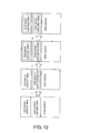
- Fig. 12 shows the movement of data with this conventional rewrite process.
- the rewrite process for flash memory sectors other than the boot memory portion is run by the boot data stored in the boot memory portion, and the boot data is rewritten with newly downloaded boot block rewrite data.
- the boot block rewrite data is acquired in a first download process by the boot data, the data stored in the main memory portion (the main data) is erased, and the acquired boot block rewrite data is written to the main memory portion (I in Fig. 12).
- the new boot data is then acquired by the boot block rewrite data in a second download step, the boot memory portion is erased, and the new boot data is written to the boot memory portion (II in Fig. 12).
- New main data, if any, is then acquired in a third download step by the new boot data, the boot block rewrite data is erased from the main memory portion, and the acquired new main data is then written to the main memory portion (Fig. 12, III). If it is not necessary to update the main data, the old main data (the data that was erased in the first step) is acquired again in the third download step and written to the main memory portion.
- the present invention is directed to solving these problems and its object is to provide a control system and a control method for rewriting flash memory that, by simplifying the rewrite process, reduce the time required by and the incidence of errors in the rewrite process while also preventing the electronic device employing the flash memory from becoming unbootable.
- This invention also provides a program for executing the steps of the control method, and a data storage medium carrying this program.
- the method of this invention can also be provided as a program executable by a machine such as the controller of an electronic device.
- the program can be embodied on various data storage media as well as the Internet and other communication media. Examples of these data storage media include Compact Discs (CD), floppy disks, hard disks, magneto-optical discs, Digital Versatile Discs (DVD), magnetic tape, and semiconductor memory modules.
- Fig. 1 shows the hardware configuration of a memory rewrite control system for flash memory.
- This control system 100 has rewritable flash memory 101 divided into sectors, i.e., units of batch-erasable storage area, read/write RAM 102, and a CPU 103 for controlling the control system 100 and for controlling the electronic device comprising the control system 100.
- the flash memory 101 stores font data, for example, a main program for controlling the normal operation of the electronic device, and a boot program for controlling the startup process of the electronic device and for rewriting data in flash memory 101.
- the one or more sectors storing the boot program are referred to below as the "boot memory portion”, and the one or more sectors storing the main program and data such as the font data is referred to as the "main memory portion".
- data constituting the boot program is referred to as the "boot data”
- main data data constituting the main program, font data, and other data stored in the main memory portion
- boot memory portion and main memory portion as used herein may include blocks of plural sectors that are the batch-erasable storage units in the flash memory.
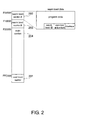
- Fig. 2 shows an example of the sector configuration of a flash memory device. This configuration is described below using a boot memory portion comprising three sectors by way of example.
- the three sectors forming the boot memory portion of flash memory 101 are first boot sector 201, second boot sector 202, and third boot sector 203.
- Boot data required to implement the minimum functions needed to boot the electronic device is stored in first boot sector 201. These minimum functions include, for example, initializing the CPU 103 and the stack, a write/read test of the RAM 102 and other tests such as a write/read test of a gate array register, and evaluations such as a boot mode evaluation.
- the first boot sector 201 is also called the “cold boot sector”
- the data stored in the cold boot sector 201 is called the “cold boot data”
- the process run by the cold boot data is called the "cold boot process”.
- Boot data for performing functions during startup other than the minimum functions (that is, functions during startup in the memory rewrite mode) and functions for rewriting data in flash memory 101 is stored in second boot sector 202.
- These functions performed during startup other than the minimum functions include determining the type of communication interface, processes appropriate to the communication interface, and processes invoked by status commands (such as returning the firmware version ID).
- a process for rewriting main data and boot data stored in sectors other than the cold boot sector 201 and second boot sector 202 itself is run by this boot data for executing a function for rewriting data in flash memory 101.
- this second boot sector 202 is referred to as warm boot sector A, the warm boot data stored in warm boot sector A 202 is called “warm boot data A”, and the warm boot process run by warm boot data A is called “warm boot process A”.
- Boot data substantially identical to warm boot data A for performing functions during startup other than the minimum functions (that is, functions during startup in the memory rewrite mode) and functions for rewriting data in flash memory 101 is stored in third boot sector 203.
- a process for rewriting main data and boot data stored in the flash memory 101 in sectors other than the cold boot sector 201 and third boot sector 203 itself is run by this boot data for executing a function for rewriting data in flash memory 101.
- this third boot sector 203 is referred to as warm boot sector B, the warm boot data in warm boot sector B 203 is called “warm boot data B", and the warm boot process run by warm boot data B is called "warm boot process B".
- This sector configuration means that the warm boot process run from one warm boot sector rewrites the warm boot data in the other warm boot sector, and at least one warm boot sector is assured of operating normally.
- a checksum for verifying each warm boot sector (that is, whether the warm boot data is correctly stored and held in memory), a warm boot update count denoting how many times the warm boot data has been updated, and a warm boot ID for identifying the warm boot sector are also stored in warm boot sectors A 202 and B 203.
- the checksum and warm boot update count are used to evaluate updated boot data. More specifically, based on the checksum and warm boot update count, the cold boot process finds the warm boot sector storing the most recent normal (i.e., usable) warm boot data, and runs the warm boot process according to the warm boot data stored in that warm boot sector.
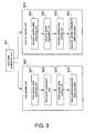
- Fig. 3 shows an example of a function block diagram relating to the memory rewrite process of this control system.
- the control system 100 has a boot data evaluation unit 301, a first rewrite unit 302, and a second rewrite unit 303.
- the first rewrite unit 302 has a first update data receiving unit 321, first sector evaluation unit 322, first update data writing unit 323, and first update evaluation data operator 324.
- the second rewrite unit 303 has a second update data receiving unit 331, second sector evaluation unit 332, second update data writing unit 333, and second update evaluation data operator 334.
- the boot data evaluation unit 301 determines, based on the checksum and warm boot update count stored in warm boot sector A 202 and warm boot sector B 203 as the boot data update evaluation data, whether to run warm boot process A, or to run warm boot process B.
- the first rewrite unit 302 can rewrite data stored in sectors in flash memory 101 other than cold boot sector 201 and warm boot sector A 202.
- the warm boot data B stored in warm boot sector B 203 can therefore be rewritten by first rewrite unit 302.
- the first update data receiving unit 321 of first rewrite unit 302 receives update data from a host using a specified communication interface.
- the update data is transmitted in data units (record units) of a specified size according to a specified format.
- the first sector evaluation unit 322 of first rewrite unit 302 determines what sector in flash memory 101 stores the update data received by the first update data receiving unit 321, and does not run the rewrite process using the update data if the data is stored in cold boot sector 201 or warm boot sector A 202.
- the first update data writing unit 323 of first rewrite unit 302 writes the update data to the specified (identified) sector in flash memory 101 other than the cold boot sector 201 and warm boot sector A 202.
- the first update evaluation data operator 324 of first rewrite unit 302 calculates and updates the checksum of the rewritten warm boot sector B 203 in flash memory 101 and the checksum of the main memory portion 204, and the warm boot update count of the warm boot sector B 203 based on the warm boot update count of warm boot sector A 202.
- the second rewrite unit 303 can rewrite data stored in sectors in flash memory 101 other than the cold boot sector 201 and warm boot sector B 203.
- the warm boot data A stored in warm boot sector A 202 can therefore be rewritten by second rewrite unit 303.
- the second update data receiving unit 331 of second rewrite unit 303 receives update data from a host using a specified communication interface.
- the update data is transmitted in data units (record units) of a specified size according to a specified format.
- the second sector evaluation unit 332 of second rewrite unit 303 determines what sector in flash memory 101 stores the update data received by the second update data receiving unit 331, and does not run the rewrite process using the update data if the data is stored in cold boot sector 201 or warm boot sector B 203.
- the second update data writing unit 333 of second rewrite unit 303 writes the update data to the specified (identified) sector in flash memory 101 other than the cold boot sector 201 and warm boot sector B 203.
- the second update evaluation data operator 334 of second rewrite unit 303 calculates and updates the checksum of the rewritten warm boot sector A 202 in flash memory 101 and the checksum of the main memory portion 204, and the warm boot update count of the warm boot sector A 202 based on the warm boot update count of warm boot sector B 203.
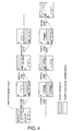
- Fig. 4 shows the rewrite sequence of warm boot data using two warm boot sectors.
- An electronic device comprising this control system is shipped with warm boot data A and warm boot data B respectively stored in warm boot sector A 202 and warm boot sector B 203 of flash memory 101.
- the warm boot update count is initialized to 1 in one warm boot sector and to 0 in the other warm boot sector.
- the warm boot update count for warm boot sector A 202 is initialized to 1
- the warm boot update count is initialized to 0 for warm boot sector B 203.
- Whether the most recent warm boot process run by the cold boot process is warm boot process A or warm boot process B is determined based on the checksum of the warm boot sector area and the warm boot update count in warm boot sector A 202 and warm boot sector B 203. If the checksum is normal for both warm boot sectors A and B, the warm boot process of the warm boot sector with the highest warm boot update count (that is, the most recently written warm boot sector) is run. Furthermore, if the checksum is normal for only warm boot sector A 202 or warm boot sector B 203, the warm boot process of the warm boot sector having a normal checksum is run.
- the warm boot process of the selected warm boot sector rewrites the warm boot data in the other (non-selected) warm boot sector, and then updates the warm boot update count.
- the warm boot process that executes is warm boot process A as shown in Fig. 4.
- the rewritten warm boot sector is therefore warm boot sector B 203.
- warm boot process A updates warm boot data B in warm boot sector B 203.
- the warm boot update count for warm boot sector B 203 becomes the warm boot update count of warm boot sector A 202 plus 1. More specifically, the warm boot update count of the updated warm boot sector always becomes greater than the warm boot update count of the warm boot sector from which the warm boot process runs. The only exception to this is when the update count is FFFFh, in which case the next value is 0. In other words when the warm boot update count has been written 10000h times, it is reset to the shipping (initialized) state.
- Fig. 5 is a flow chart showing an example of the boot process run by the cold boot process from cold boot sector 201, warm boot process A from warm boot sector A 202, and warm boot process B from warm boot sector B 203.
- Initialization including initializing the CPU 103 and stack, tests, including a W/R check of RAM 102 and the gate array registers, and evaluations, including determining the startup mode, is first performed (S501).
- Whether the memory rewrite mode is selected is determined by detecting, for example, the state of DIP switches of the electronic device (S502). If the memory rewrite mode is not set, that is, if the normal operating mode is set (S502 returns No), the checksum of the main memory portion 204 is verified (S512) and whether the checksum is correct, that is, whether the data in main memory portion 204 is correct, is determined (S513). If the checksum is wrong (S513 returns No), an error process such as displaying an error message is run (S515). If the checksum is correct (S513 returns Yes), the steps of the main program run in the normal operating mode are executed (S514).
- warm boot update count of warm boot sector A 202 is greater that of warm boot sector B 203 (S508 returns Yes), that is, if warm boot data A is newer than warm boot data B, the flash memory rewrite process is run according to warm boot process A read from warm boot sector A 202 (S510).
- warm boot update count of warm boot sector A 202 is less than that of warm boot sector B 203 (S508 returns No), that is, if warm boot data B was updated more recently than warm boot data A, the flash memory rewrite process is run according to warm boot process B read from warm boot sector B 203 (S509).
- the electronic device shifts from the normal operating mode to the memory rewrite mode as a result of receiving a select-rewrite-mode command from the host (S516), and rewrites flash memory content (S503 to S511).
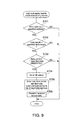
- Fig. 6 is a flow chart showing an example of the flash memory rewrite process executed by the warm boot processes (A or B) in a first embodiment of this invention.
- the warm boot process being executed will be referred to as the "active warm boot process” and the other warm boot process will be referred to as the “inactive warm boot process”.
- active warm boot process the warm boot process being executed
- inactive warm boot process the warm boot process
- the same attributes active and inactive will be used in a similar way together with the warm boot sector and warm boot data.
- the type of the communication interface for receiving update data for rewriting flash memory 101 from the host is identified and initialization is completed (S601).
- the warm boot ID identifying the warm boot process and warm boot sector is then acquired (S602).
- the update data is then received in units of one record (S603).
- a received record of update data is below referred to as the "received record data”.
- the received record data is the last record or not, i.e., whether receiving update data ends or not, is then determined (S604).
- the received record data is not the last record (S604 returns No)
- the received record data contains a start address identifying the target sector of the flash memory. This sector may be any sector other than the cold boot sector 201 or the active warm boot sector.
- the received record data is update data for the sector of the flash memory in which it should be stored (S605 returns Yes)
- a write process is run for the received record data (S606).
- An OK status report indicating that reception was completed normally is then sent to the host (S607), the procedure loops back to step S603, and the next record of update data is received. If the inactive warm boot sector is rewritten, the warm boot update count is calculated and written.
- the received record data is not update data for the flash memory sector that will store the data (S605 returns No)
- the received record data is discarded, the process returns to step S603, and the next update data record is received.
- the checksum of the inactive warm boot sector and/or the checksum of the main memory portion 204, where the received record data was written is calculated and written (S608), the CPU 103 is reset (S609), and the write process ends.
- the CPU 103 could be reset (S609) and the memory write process ended when a rewrite mode termination command is received from the host (S610).
- the update data sent from the host could be compiled for each individual sector, that is, for warm boot sector A 202, B 203, and main memory portion 204, or it could be a block of update data for any number of multiple sectors.
- the warm boot update count could also be calculated and written together with the checksum in step S608.
- Fig. 7 shows the flash memory rewrite range in this first embodiment of the invention.
- Fig. 7 (a) shows the flash memory rewrite range when warm boot process A is the active warm boot process
- Fig. 7 (b) shows the range when warm boot process B is the active one.
- data other than the following four types is rewritten based on the received record data.
- checksum is calculated during a rewrite process controlled by a warm boot process, and the value is written to flash memory (S608).
- a first rewriting method sequentially receives and rewrites update data for an entire sector as record data in all sectors of the flash memory 101. Record data for unused areas is sent as 0xff. If the received record data is the first update data for the sector to be rewritten (the "update sector"), that is, the received record data will be written to the beginning of the update sector, all data in the update sector is erased and the received record data is written to the update sector based on the start address. If the received record data is not update data written to the beginning of the update sector, the received record data is simply written to the update sector from the location identified by the start address.
- a second rewriting method receives update data for the part of the warm boot sector where data is stored and rewrites the entire sector. For sectors other than warm boot sectors, this second method receives only the data that is to be updated, and rewrites only that part corresponding to the received record data.
- the data in the update sector is copied to RAM to produce a sector image, received record data to be used for updating is written to the sector image in RAM, and all data in the update sector is then erased if the received record data is to be written to the beginning of the sector. If the received record data is not the first update data in the update sector, all received record data for parts where there is data is written to the sector image in RAM, and the sector image in RAM is then written back to the update sector.
- a sector other than a warm boot sector is the update sector, all data from the update sector is copied to RAM, received record data for those parts to update is written, all data is erased from the update sector, and the sector image is then written back from RAM to the update sector.
- a third rewriting method receives only the data to be updated in all sectors of the flash memory 101, and rewrites only the parts corresponding to the received record data. All data in the update sector is copied to RAM to form a sector image, received record data for the part to be updated is written to the sector image in RAM, all data is then erased from the update sector, and the sector image written to RAM is written back to the update sector.
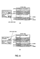
- Fig. 8 illustrates details of this warm boot sector rewrite process.
- Fig. 8 (a) shows rewriting warm boot sector B when warm boot process A is executing.
- Fig. 8 (b) shows rewriting warm boot sector A when warm boot process B runs.
- Fig. 8 (a) for example, when warm boot process A runs warm boot data B for warm boot sector B 203 is sequentially received and written to warm boot sector B 203 based on the start address of the received record data. The warm boot update count is then calculated for warm boot sector B 203 and written to a specific area in warm boot sector B 203. If the warm boot update count of warm boot sector A 202 is N at this time, the warm boot update count for warm boot sector B 203 becomes (N+1). The checksum of warm boot sector B 203 is then calculated and written to a specific area in warm boot sector B 203.
- warm boot process B runs essentially the same actions occur as when warm boot process A runs as shown in Fig. 8 (b). That is, warm boot data A for warm boot sector A 202 is rewritten based on the received record data, and the warm boot update count and checksum of warm boot sector A 202 are calculated and written to memory.
- This second embodiment of the invention differs from the first embodiment above in that it can rewrite the cold boot sector 201 in addition to warm boot sectors A 202 and B 203 and the main memory portion 204. This difference between the second and first embodiments is described below.
- a danger with rewriting the cold boot data stored in the cold boot sector 201 is that a write error, for example, could render the electronic device unbootable.
- the cold boot sector cannot be rewritten and only warm boot sectors 202, 203 and the main memory portion 204 are rewritable sectors, thereby protecting the cold boot data. This is referred to as the "normal rewrite mode" below.
- the cold boot process is composed of the minimal functions needed to boot the electronic device, thereby reducing the potential need to rewrite the cold boot data. It may still be necessary to rewrite the cold boot data, however, in order to correct bugs in the cold boot data (startup procedure) or to upgrade the cold boot data.
- a control system 100 according to this second embodiment of the invention therefore also provides a cold boot sector rewrite mode so that the cold boot sector 201 can also be rewritten in addition to rewriting warm boot sectors 202, 203 and the main memory portion 204.
- the control system 100 of this second embodiment detects in the update data sent from the host for rewriting data stored in the flash memory 101 indicia for writing specific data of a specific data length to a specific address in flash memory 101, it goes to the cold boot sector rewrite mode.
- This specific address and specific data can be predefined as desired.
- the specific data is the 7-byte long character code REWRITE.
- the specific address is 0xF1FFE0 if the process is running from warm boot sector A 202, and is 0xF0FFE0 if the process is running from warm boot sector B 203.
- Each of these two addresses can be written in one update data record as the specific address for writing data.
- the cold boot sector rewrite mode can be entered regardless of which warm boot sector will be the active one.
- warm boot data A stored in warm boot sector A 202 enables rewriting boot data stored in flash memory 101 in sectors other than warm boot sector A 202 itself, and rewriting the main data.
- warm boot data B stored in warm boot sector B 203 enables rewriting boot data stored in flash memory 101 in sectors other than warm boot sector B 203 itself, and rewriting the main data.
- the first rewrite unit 302 is a function of warm boot process A stored in warm boot sector A 202 (Fig. 2), and can rewrite data stored in any sector in flash memory 101 other than warm boot sector A 202 itself. That is, cold boot data stored in cold boot sector 201, warm boot data B stored in warm boot sector B 203, and main data stored in main memory portion 204 can be rewritten by the first rewrite unit 302.
- the first sector evaluation unit 322 determines which sector in flash memory 101 is to store the update data received by the first update data receiving unit 321. If it is warm boot sector A 202, the update data is not written. The received update data is also interpreted to determine whether to move to the cold boot sector rewrite mode. If the cold boot sector rewrite mode is not indicated and the sector to store the update data is the cold boot sector 201, the update data is not written.
- the first update data writing unit 323 writes the update data to the specified sector in flash memory 101.
- the second rewrite unit 303 is a function of warm boot process B in warm boot sector B 203 (Fig. 2), and can rewrite data stored in any sector in flash memory 101 other than warm boot sector B 203 itself. That is, second rewrite unit 303 can write cold boot data to cold boot sector 201, warm boot data A to warm boot sector A 202, and main data to main memory portion 204.
- the second sector evaluation unit 332 determines which sector in flash memory 101 stores the update data received by the second update data receiving unit 331. If it is warm boot sector B 203, the update data is not written. The received update data is also interpreted to determine if the cold boot sector rewrite mode is indicated. If entering the cold boot sector rewrite mode is not indicated and the sector to store the update data is the cold boot sector 201, the update data is not written.
- the second update data writing unit 333 writes the update data to the specified sector in flash memory 101.
- Fig. 9 is a flow chart showing the process for determining whether to move to the cold boot sector rewrite mode. This process determines whether to move from the normal rewrite mode to the cold boot sector rewrite mode, and is run as part of the memory rewrite process (S509, S510) shown in Fig. 5.
- each record of received update data is analyzed to determine if the write address in the data record is one of the specified address (that is, addresses 0xF1FFE0 and 0xF0FFE0 in this embodiment) (S701). If the write address is one of these specified addresses (S701 returns Yes ), whether the length of the data is the specified data length (7 bytes in this embodiment) is determined (S702). If it is (S702 returns Yes), whether the content of the received record is the specified data (the character codes for REWRITE in this embodiment) is determined (S703). If it is (S703 returns Yes ), an OK status report indicating that the data was received is sent to the host (S704). A flag for setting the cold boot sector 201 to a rewritable mode in flash memory 101 is then set (S705), and the received data record is discarded (S706).
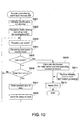
- Fig. 10 is a flow chart showing an example of a flash memory rewrite process controlled by a warm boot process (A or B) in this second embodiment of the invention.
- This process is substantially the same as the process of the first embodiment shown in Fig. 6. It differs in that in this second embodiment after a data record is received (S803) the cold boot sector rewrite mode evaluation process shown in Fig. 9 runs (S804).
- the cold boot sector rewrite mode is entered or the normal rewrite mode is maintained based on the result.
- Steps S805 to S811 are the same as steps S604 to S610 in the first embodiment.
- the rewritable sectors are all sectors other than the cold boot sector 201 and the active warm boot sector; in the cold boot sector rewrite mode, all sectors other than the active warm boot sector are rewritable.
- step S804 If the cold boot sector rewrite mode is activated in step S804, the flag set to enable rewriting the cold boot sector 201 is cleared in the termination process of step S810 so that the cold boot sector 201 cannot be rewritten.
- the update data sent from the host can be compiled individually for each sector, that is, cold boot sector 201, warm boot sector A 202 or B 203, and main memory portion 204, or for writing to a desired plurality of sectors.
- Fig. 11 shows the rewritable flash memory ranges in this second embodiment of the invention.
- Fig. 11 (a) shows the range that is rewritable when warm boot process A runs
- Fig. 11 (b) shows the range that is rewritable when warm boot process B runs.
- data other than the three types described below are rewritten based on the received record data.
- checksum is calculated during a rewrite process controlled by a warm boot process, and the value is written to flash memory (S809).
- the cold boot data is not included in the rewritable sector range when operating in the normal rewrite mode. This is the same as in the first embodiment.
- the present invention can be used when there are three or more warm boot sectors.
- the cold boot data stored in the cold boot sector can be configured to determine which of the warm boot sectors is to be the active one based on the checksum and warm boot update count, and read and execute the warm boot code from that sector.
- the invention provides a cold boot sector and at least two other boot sectors in flash memory.
- Cold boot data containing the minimal functions needed to boot the device having the flash memory is stored in the cold boot sector.
- Boot data for running a function (and functions of the startup process other than the functions contained in the cold boot data) for rewriting flash memory sectors including the cold boot sector but not including the active boot sector is stored in at least two other boot sectors. It is therefore possible to prevent the device from becoming unbootable as a result of boot memory portion rewrite errors. For example, when a new function is added to a boot process that is already functioning normally, the electronic device can be prevented from becoming unbootable due to a write error during the boot data rewrite process by writing boot data for the new function to another warm boot sector as warm boot data.
- the cold boot sector can be set to a rewritable state by sending data indicating writing specific data to a specific address in the update data, and the cold boot data can therefore be easily rewritten. It is therefore not necessary to provide a special program for rewriting the cold boot data, and the cold boot data can be rewritten using the same procedure used to rewrite warm boot data and the main data.
- the cold boot data, warm boot data, and main data can be rewritten with a single download operation. Operation is thus simplified and the chance of errors occurring is greatly reduced. Less time is also required for the rewrite process.
Landscapes
- Engineering & Computer Science (AREA)
- Theoretical Computer Science (AREA)
- General Engineering & Computer Science (AREA)
- Software Systems (AREA)
- Physics & Mathematics (AREA)
- General Physics & Mathematics (AREA)
- Computer Security & Cryptography (AREA)
- Techniques For Improving Reliability Of Storages (AREA)
- Stored Programmes (AREA)
- Information Retrieval, Db Structures And Fs Structures Therefor (AREA)
Abstract
Description
- Fig. 1
- shows the hardware configuration of the control system;
- Fig. 2
- shows the sector configuration of flash memory;
- Fig. 3
- is a function block diagram relating to the memory rewrite process;
- Fig. 4
- shows the warm boot data rewrite sequence using two warm boot memory portions;
- Fig. 5
- is a flow chart of the boot process;
- Fig. 6
- is a flow chart of a rewrite process using the warm boot process according to a first embodiment of the invention;
- Fig. 7(a)
- shows the rewritable flash memory sectors when warm boot process A is executing, and (b) shows the rewritable flash memory sectors when warm boot process B is executing, according to the first embodiment;
- Fig. 8(a)
- describes rewriting warm boot sector B when warm boot process A is running, and (b) describes rewriting warm boot memory portion A when warm boot process B is running;
- Fig. 9
- is a flow chart showing a process for determining whether to enter a cold boot memory portion rewrite mode;
- Fig. 10
- is a flow chart of a rewrite process using the warm boot process according to a second embodiment of the invention;
- Fig. 11(a)
- shows the rewritable flash memory sectors when warm boot process A is executing, and (b) shows the rewritable flash memory sectors when warm boot process B is executing, according to the second embodiment; and
- Fig. 12
- describes data movement with a conventional rewrite process.
- Cold boot data: boot data that is not rewritten
- Active warm boot data in the active warm boot sector: when warm boot process A is running, warm boot data A; when warm boot process B is running, warm boot data B.
- Checksum of the inactive warm boot sector: when warm boot process A is running, the
checksum of warm
boot sector B 203; when warm boot process B is running, the checksum of warmboot sector A 202. - Checksum of main memory portion 204: the checksum of the entire main memory portion.
- Active warm boot data in an active warm boot sector: when warm boot process A is running, warm boot data A; when warm boot process B is running, warm boot data B.
- Checksum of the inactive warm boot sector: when warm boot process A is running, the
checksum of warm
boot sector B 203; when warm boot process B is running, the checksum of warmboot sector A 202. - Checksum of main memory portion 204: the checksum of the entire main memory portion.
Claims (13)
- A control system for controlling rewriting of a flash memory (101) comprising plural sectors and enabling erasing data in units of one sector, said sectors including a cold boot sector (201) for storing cold boot data, N other boot sectors (202, 203) for storing boot data selectively activated by said cold boot data, wherein N ≥ 2, and a main memory portion (204) for storing main data activated by said cold boot data or the activated boot data, the control system comprising:a boot data evaluation unit (301) for selecting the boot data to be activated by the cold boot data from the boot data stored in said N other boot sectors (202, 203) based on boot sector update evaluation data stored in each of said N other boot sectors (202, 203); andrewrite means (302, 303) for rewriting data stored in the main memory portion (204) and/or a boot sector other than that storing the boot data selected by the boot data evaluation unit (301).
- The control system of claim 1, wherein the rewrite means (302, 303) comprises:an update data receiving unit (321, 331) for receiving update data for rewriting data stored in the flash memory (101);a sector evaluation unit (322, 332) for selecting the boot sector or the main memory portion (204) to store the update data based on the update data received by the update data receiving unit (321, 331);an update data writing unit (323, 333) for writing the update data received by the update data receiving unit (321, 331) to the sector selected by the sector evaluation unit (322, 332); andan update evaluation data operator (324, 334) for calculating and updating the boot data update evaluation data when the sector selected by the sector evaluation unit (322, 332) is any of said N other boot sectors.
- The control system of claim 2, wherein the rewrite means comprises:N rewrite units (302, 303) each for rewriting data stored in a sector other than a respective one of said N other sectors if said respective other sector is the one storing the boot data selected by said boot data evaluation unit (301).
- The control system of claim 2 or 3, wherein the rewrite means (302, 303) is adapted to recognize specific data among the update data received by the update data receiving unit (321, 331) said specific data having a specific data length and indicating a specific address in flash memory (101), and to enable rewriting to the cold boot sector (201) in response to the specific data being recognized.
- The control system of claim 2, wherein the rewrite means comprises:N rewrite units (302, 303) each for rewriting data stored in a sector other than the cold boot sector (201) and a respective one of said N other sectors if said respective other sector is the one storing the boot data selected by said boot data evaluation unit (301).
- The control system of any one of the preceding claims, wherein the boot data update evaluation data includes:a boot update count value; anda boot sector checksum for verifying the boot data stored in the respective one of the N other boot sectors (202, 203);said boot data evaluation unit (301) being adapted to select the boot data of that one of said N other boot sectors (202, 203) which has the highest boot update count that indicates the cumulative number of times boot data has been rewritten in any of said N other boot sectors (202, 203).
- A method of controlling rewriting a flash memory (101) comprising plural sectors and enabling erasing data in units of one sector, said sectors including a cold boot sector (201) for storing cold boot data, N other boot sectors (202, 203) for storing boot data selectively activated by said cold boot data, wherein N ≥ 2, and a main memory portion (204) for storing main data activated by said cold boot data or the activated boot data, the method comprising the steps of:(a) selecting the boot data to be activated by the cold boot data from the boot data stored in said N other boot sectors (202, 203) based on boot sector update evaluation data stored in each of said N other boot sectors (202, 203); and(b) rewriting data stored in the main memory portion (204) and/or a boot sector other than that storing the boot data selected in step (a).
- The method of claim 7, wherein step (b) comprises:(b1) receiving update data for rewriting data stored in flash memory (101);(b2) selecting the boot sector or the main memory portion (204) to store the update data based on the update data received in step (b1);(b3) writing the update data received in step (b1) to the sector selected in step (b2); and(b4) calculating and updating the boot data update evaluation data when the sector selected in step (b2) is any of said N other boot sectors.
- The method of claim 7, wherein step (b) comprises:rewriting data stored in a sector other than the cold boot sector (201) and that one of said N other boot sectors (202, 203) that stores the boot data selected in step (a).
- The method of claim 8, wherein step (b) comprises recognizing specific data among the update data received in step (b1), said specific data having a specific data length and indicating a specific address in flash memory (101), and enabling rewriting to the cold boot sector (201) in response to the specific data having being recognized.
- The method of any one of claims 7 to 10, wherein the boot data update evaluation data includes:wherein step (a) comprises selecting the boot data of that one of said N other boot sectors (202, 203) which has the highest boot update count that indicates the cumulative number of times boot data has been rewritten in any of said N other boot sectors (202, 203).a boot update count value; anda boot sector checksum for verifying the boot data stored in the respective one of the N other boot sectors (202, 203);
- A program of instruction for execution by a machine for performing the method of any one of claims 7 to 11 when executed by the machine.
- A computer-readable data storage medium carrying out the program of claim 12.
Applications Claiming Priority (4)
| Application Number | Priority Date | Filing Date | Title |
|---|---|---|---|
| JP2002170633A JP4062421B2 (en) | 2002-06-11 | 2002-06-11 | Memory rewrite control method and program for executing each step of memory rewrite control method |
| JP2002170633 | 2002-06-11 | ||
| JP2002255270A JP4062429B2 (en) | 2002-08-30 | 2002-08-30 | Memory rewrite control method and program for executing each step of memory rewrite control method |
| JP2002255270 | 2002-08-30 |
Publications (2)
| Publication Number | Publication Date |
|---|---|
| EP1372068A2 true EP1372068A2 (en) | 2003-12-17 |
| EP1372068A3 EP1372068A3 (en) | 2006-02-08 |
Family
ID=29586049
Family Applications (1)
| Application Number | Title | Priority Date | Filing Date |
|---|---|---|---|
| EP03011150A Withdrawn EP1372068A3 (en) | 2002-06-11 | 2003-05-23 | System, method and program for rewriting a flash memory |
Country Status (4)
| Country | Link |
|---|---|
| US (1) | US7383431B2 (en) |
| EP (1) | EP1372068A3 (en) |
| KR (1) | KR100507884B1 (en) |
| CN (1) | CN100407177C (en) |
Cited By (6)
| Publication number | Priority date | Publication date | Assignee | Title |
|---|---|---|---|---|
| EP1591893A1 (en) * | 2004-04-29 | 2005-11-02 | Alcatel | Method and system for fail-safe updating of boot code |
| EP1693740A3 (en) * | 2005-02-16 | 2007-04-04 | Seiko Epson Corporation | Data processing apparatus and control method for a data processing apparatus |
| EP1647885A3 (en) * | 2004-10-14 | 2007-11-21 | Sharp Kabushiki Kaisha | Rewriting a non-volatile memory |
| WO2009103728A1 (en) * | 2008-02-22 | 2009-08-27 | Robert Bosch Gmbh | Method and device for storing information data |
| EP2646908A4 (en) * | 2010-11-29 | 2015-02-18 | Thomson Licensing | METHOD AND DEVICE FOR DISTINCTING BETWEEN COLD START AND WARM START |
| CN111488168A (en) * | 2019-12-25 | 2020-08-04 | 湖北航天飞行器研究所 | Weapon system control software safety upgrading method based on boot secondary loading |
Families Citing this family (23)
| Publication number | Priority date | Publication date | Assignee | Title |
|---|---|---|---|---|
| KR100630185B1 (en) * | 2004-07-07 | 2006-09-29 | 삼성전자주식회사 | Start-up device and method of mobile terminal system supporting start-up mode using hard wired cord |
| JP4759983B2 (en) * | 2004-11-04 | 2011-08-31 | 船井電機株式会社 | Firmware rewriting method for disk device and firmware rewriting program |
| JP2007025821A (en) * | 2005-07-12 | 2007-02-01 | Seiko Epson Corp | Information processing apparatus and information processing apparatus control method |
| US8001385B2 (en) * | 2006-06-21 | 2011-08-16 | Intel Corporation | Method and apparatus for flash updates with secure flash |
| US7991942B2 (en) * | 2007-05-09 | 2011-08-02 | Stmicroelectronics S.R.L. | Memory block compaction method, circuit, and system in storage devices based on flash memories |
| US20080282024A1 (en) * | 2007-05-09 | 2008-11-13 | Sudeep Biswas | Management of erase operations in storage devices based on flash memories |
| US7882301B2 (en) * | 2007-05-09 | 2011-02-01 | Stmicroelectronics S.R.L. | Wear leveling in storage devices based on flash memories and related circuit, system, and method |
| US8041883B2 (en) | 2007-05-09 | 2011-10-18 | Stmicroelectronics S.R.L. | Restoring storage devices based on flash memories and related circuit, system, and method |
| US7917790B2 (en) * | 2008-01-17 | 2011-03-29 | Broadcom Corporation | Separate power island for high performance processor that reboots to second boot sector |
| US8438423B1 (en) * | 2009-03-31 | 2013-05-07 | American Megatrends, Inc. | Invalid setup recovery |
| CN101763279B (en) * | 2010-01-15 | 2012-12-12 | 上海维宏电子科技股份有限公司 | BootLoader architectural design method |
| JP5691752B2 (en) | 2011-04-01 | 2015-04-01 | セイコーエプソン株式会社 | Data rewriting method, data rewriting device and rewriting program |
| KR101997079B1 (en) * | 2012-07-26 | 2019-07-08 | 삼성전자주식회사 | Storage devie comprising variable resistance memory and operation method thereof |
| WO2014175867A1 (en) | 2013-04-23 | 2014-10-30 | Hewlett-Packard Development Company, L.P. | Verifying controller code and system boot code |
| CN105122261B (en) * | 2013-04-23 | 2020-04-24 | 惠普发展公司,有限责任合伙企业 | Method for recovering from damaged system starting code and computing device |
| WO2014175865A1 (en) | 2013-04-23 | 2014-10-30 | Hewlett-Packard Development Company, L.P. | Repairing compromised system data in a non-volatile memory |
| JP7085029B2 (en) * | 2019-01-30 | 2022-06-15 | 株式会社デンソートリム | Memory rewrite history recording device |
| WO2020159533A1 (en) | 2019-02-01 | 2020-08-06 | Hewlett-Packard Development Company, L.P. | Security credential derivation |
| US11520662B2 (en) | 2019-02-11 | 2022-12-06 | Hewlett-Packard Development Company, L.P. | Recovery from corruption |
| EP3929784A1 (en) * | 2020-06-23 | 2021-12-29 | Siemens Aktiengesellschaft | Boot device for a computer element and method for booting a computer element |
| NO346155B1 (en) * | 2020-10-26 | 2022-03-28 | Kongsberg Defence & Aerospace As | Configuration authentication prior to enabling activation of a FPGA having volatile configuration-memory |
| JP7768850B2 (en) * | 2022-06-30 | 2025-11-12 | 株式会社デンソー | Electronic control device, reproduction method and reproduction program |
| CN115712393A (en) * | 2022-11-23 | 2023-02-24 | 深圳市合广测控技术有限公司 | Flash memory data writing method, device, equipment and storage medium |
Family Cites Families (36)
| Publication number | Priority date | Publication date | Assignee | Title |
|---|---|---|---|---|
| US5473775A (en) * | 1991-10-11 | 1995-12-05 | Kabushiki Kaisha Toshiba | Personal computer using flash memory as BIOS-ROM |
| JP2971267B2 (en) | 1991-10-11 | 1999-11-02 | 株式会社東芝 | Personal computer using flash memory as BIOS-ROM |
| US5522076A (en) * | 1993-05-13 | 1996-05-28 | Kabushiki Kaisha Toshiba | Computer system having BIOS (basic input/output system)-ROM (Read Only Memory) writing function |
| JPH06324857A (en) | 1993-05-13 | 1994-11-25 | Toshiba Corp | Computer system |
| JP3215237B2 (en) | 1993-10-01 | 2001-10-02 | 富士通株式会社 | Storage device and method for writing / erasing storage device |
| JPH0869376A (en) | 1994-08-31 | 1996-03-12 | Hitachi Ltd | Rewriting control circuit of BIOS |
| CN100543667C (en) * | 1996-04-11 | 2009-09-23 | 株式会社日立制作所 | Disk drive |
| US6282675B1 (en) * | 1997-08-06 | 2001-08-28 | Macronix International Co., Ltd. | Fault-tolerant architecture for in-circuit programming |
| JPH10171659A (en) | 1996-12-10 | 1998-06-26 | Matsushita Electric Ind Co Ltd | Download method and device |
| JP4279902B2 (en) | 1997-01-31 | 2009-06-17 | ソニー株式会社 | Digital television broadcast receiving apparatus and digital television broadcast receiving program acquisition method |
| JPH10283171A (en) | 1997-04-02 | 1998-10-23 | Seiko Epson Corp | Information processing apparatus and control method thereof |
| JPH10320984A (en) | 1997-05-15 | 1998-12-04 | Sharp Corp | Storage device |
| JPH10333913A (en) | 1997-06-02 | 1998-12-18 | Hitachi Telecom Technol Ltd | Software boot control method |
| JP2914360B2 (en) * | 1997-09-30 | 1999-06-28 | ソニー株式会社 | External storage device and data processing method |
| US6298421B1 (en) | 1998-01-12 | 2001-10-02 | Brother Kogyo Kabushiki Kaisha | Data storage device |
| JPH11212791A (en) | 1998-01-23 | 1999-08-06 | Brother Ind Ltd | Data rewriting device |
| US6167532A (en) * | 1998-02-05 | 2000-12-26 | Compaq Computer Corporation | Automatic system recovery |
| JPH11249968A (en) | 1998-03-05 | 1999-09-17 | Sanyo Electric Co Ltd | File recording method and file system |
| JPH11265282A (en) | 1998-03-17 | 1999-09-28 | Toshiba Corp | Vending machine control device |
| JP3467678B2 (en) | 1998-03-27 | 2003-11-17 | セイコーエプソン株式会社 | Information processing system, device used therefor, and control method thereof |
| JPH11297082A (en) | 1998-04-06 | 1999-10-29 | Matsushita Electric Ind Co Ltd | Flash memory data rewriting method and semiconductor memory device |
| US6275931B1 (en) * | 1998-06-22 | 2001-08-14 | Elsag International N.V. | Method and apparatus for upgrading firmware boot and main codes in a programmable memory |
| US6205548B1 (en) * | 1998-07-31 | 2001-03-20 | Intel Corporation | Methods and apparatus for updating a nonvolatile memory |
| JP2000066960A (en) | 1998-08-25 | 2000-03-03 | Fujitsu Ltd | Backup method |
| JP3769395B2 (en) | 1998-10-19 | 2006-04-26 | 株式会社日立製作所 | External storage device using non-volatile memory |
| JP2000122935A (en) | 1998-10-20 | 2000-04-28 | Sanyo Electric Co Ltd | Address converting device for nonvolatile memory |
| IL129947A (en) * | 1999-05-13 | 2003-06-24 | Tadiran Telecom Business Syste | Method and apparatus for downloading software into an embedded system |
| JP2000330850A (en) * | 1999-05-19 | 2000-11-30 | Casio Comput Co Ltd | Flash memory control method |
| JP3838840B2 (en) | 2000-01-06 | 2006-10-25 | Necエレクトロニクス株式会社 | Computer |
| JP2001209543A (en) * | 2000-01-28 | 2001-08-03 | Nec Ic Microcomput Syst Ltd | Program rewriting method for flash microcomputer |
| US6560703B1 (en) * | 2000-04-18 | 2003-05-06 | International Business Machines Corporation | Redundant updatable self-booting firmware |
| JP2001331323A (en) | 2000-05-18 | 2001-11-30 | Canon Inc | Download method, apparatus and system |
| JP2001331325A (en) | 2000-05-19 | 2001-11-30 | Nec Corp | Initial startup device, its method and recording medium |
| JP2001331379A (en) | 2000-05-22 | 2001-11-30 | Nec Microsystems Ltd | Method and device for rewriting flash memory update program |
| US6442067B1 (en) * | 2000-05-23 | 2002-08-27 | Compaq Information Technologies Group, L.P. | Recovery ROM for array controllers |
| JP2002073360A (en) | 2000-09-05 | 2002-03-12 | Casio Comput Co Ltd | Startup information rewriting device |
-
2003
- 2003-05-23 EP EP03011150A patent/EP1372068A3/en not_active Withdrawn
- 2003-06-11 KR KR10-2003-0037432A patent/KR100507884B1/en not_active Expired - Fee Related
- 2003-06-11 US US10/460,459 patent/US7383431B2/en not_active Expired - Fee Related
- 2003-06-11 CN CN031424147A patent/CN100407177C/en not_active Expired - Fee Related
Cited By (10)
| Publication number | Priority date | Publication date | Assignee | Title |
|---|---|---|---|---|
| EP1591893A1 (en) * | 2004-04-29 | 2005-11-02 | Alcatel | Method and system for fail-safe updating of boot code |
| US7313682B2 (en) | 2004-04-29 | 2007-12-25 | Alcatel Lucent | Method and system for updating boot memory that stores a fail-safe reset code and is configured to store boot code and boot updater code |
| EP1647885A3 (en) * | 2004-10-14 | 2007-11-21 | Sharp Kabushiki Kaisha | Rewriting a non-volatile memory |
| EP1693740A3 (en) * | 2005-02-16 | 2007-04-04 | Seiko Epson Corporation | Data processing apparatus and control method for a data processing apparatus |
| US7558949B2 (en) | 2005-02-16 | 2009-07-07 | Seiko Epson Corporation | Data processing apparatus and control method for verifying that version codes in selected boot sector and main sector match |
| WO2009103728A1 (en) * | 2008-02-22 | 2009-08-27 | Robert Bosch Gmbh | Method and device for storing information data |
| EP2646908A4 (en) * | 2010-11-29 | 2015-02-18 | Thomson Licensing | METHOD AND DEVICE FOR DISTINCTING BETWEEN COLD START AND WARM START |
| US9207950B2 (en) | 2010-11-29 | 2015-12-08 | Thomson Licensing | Method and device for distinguishing between cold boot and warm boot and setting a data to make it fail to determine the boot type as warm boot |
| CN111488168A (en) * | 2019-12-25 | 2020-08-04 | 湖北航天飞行器研究所 | Weapon system control software safety upgrading method based on boot secondary loading |
| CN111488168B (en) * | 2019-12-25 | 2023-09-12 | 湖北航天飞行器研究所 | Weapon system control software safety upgrading method based on boot secondary loading |
Also Published As
| Publication number | Publication date |
|---|---|
| KR20030095359A (en) | 2003-12-18 |
| US7383431B2 (en) | 2008-06-03 |
| KR100507884B1 (en) | 2005-08-17 |
| CN100407177C (en) | 2008-07-30 |
| US20040039872A1 (en) | 2004-02-26 |
| CN1469257A (en) | 2004-01-21 |
| EP1372068A3 (en) | 2006-02-08 |
Similar Documents
| Publication | Publication Date | Title |
|---|---|---|
| EP1372068A2 (en) | System, method and program for rewriting a flash memory | |
| US6560703B1 (en) | Redundant updatable self-booting firmware | |
| US6601132B2 (en) | Nonvolatile memory and method of writing data thereto | |
| US6789158B2 (en) | Method of rewriting program in a flash microcomputer | |
| KR100415371B1 (en) | Computer | |
| CN110096300B (en) | FPGA program file backup management system, operation method and upgrading method | |
| JP4791061B2 (en) | Firmware version management method and information processing apparatus for computer system | |
| JP3268130B2 (en) | Data processing device using flash EEPROM | |
| US7634648B2 (en) | Data processing apparatus and control method for a data processing apparatus that temporarily provides a plurality of boot sectors in flash ROM | |
| CN107239411B (en) | Memory management method and system for vehicle-mounted controller | |
| US8127122B2 (en) | Selection of boot drive in a computer system | |
| EP1693740A2 (en) | Data processing apparatus and control method for a data processing apparatus | |
| US20040015671A1 (en) | Single-chip microcomputer and boot region switching method thereof | |
| CN113157303A (en) | Upgrading method, embedded system, terminal and computer storage medium | |
| US20050223268A1 (en) | Method of writing non-volatile memory that avoids corrupting the vital initialization code | |
| US7007036B2 (en) | Method and apparatus for embedding configuration data | |
| EP1679599B1 (en) | File update system and boot management system of mobile communication terminal, and corresponding methods | |
| JP4238930B2 (en) | Memory rewrite control system. | |
| JP4062429B2 (en) | Memory rewrite control method and program for executing each step of memory rewrite control method | |
| JP2004013536A (en) | Flash memory rewrite control system, flash memory rewrite control method, program for executing each step of flash memory rewrite control method, and information recording medium | |
| US11507385B1 (en) | Embedded electronic device, boot method, and embedded electronic device readable recording medium with stored program | |
| JP4062421B2 (en) | Memory rewrite control method and program for executing each step of memory rewrite control method | |
| KR20070002849A (en) | Firmware update method of electronic device | |
| KR100432313B1 (en) | Method for checking errors of data downloaded to flash memory of subsystem from host system | |
| JP2002259152A (en) | Flash memory rewriting method |
Legal Events
| Date | Code | Title | Description |
|---|---|---|---|
| PUAI | Public reference made under article 153(3) epc to a published international application that has entered the european phase |
Free format text: ORIGINAL CODE: 0009012 |
|
| AK | Designated contracting states |
Kind code of ref document: A2 Designated state(s): AT BE BG CH CY CZ DE DK EE ES FI FR GB GR HU IE IT LI LU MC NL PT RO SE SI SK TR |
|
| AX | Request for extension of the european patent |
Extension state: AL LT LV MK |
|
| PUAL | Search report despatched |
Free format text: ORIGINAL CODE: 0009013 |
|
| AK | Designated contracting states |
Kind code of ref document: A3 Designated state(s): AT BE BG CH CY CZ DE DK EE ES FI FR GB GR HU IE IT LI LU MC NL PT RO SE SI SK TR |
|
| AX | Request for extension of the european patent |
Extension state: AL LT LV MK |
|
| 17P | Request for examination filed |
Effective date: 20060524 |
|
| AKX | Designation fees paid |
Designated state(s): DE ES FR GB IT NL |
|
| STAA | Information on the status of an ep patent application or granted ep patent |
Free format text: STATUS: THE APPLICATION HAS BEEN WITHDRAWN |
|
| 18W | Application withdrawn |
Effective date: 20090626 |