EP1371886B1 - Endschalter - Google Patents
Endschalter Download PDFInfo
- Publication number
- EP1371886B1 EP1371886B1 EP03012987A EP03012987A EP1371886B1 EP 1371886 B1 EP1371886 B1 EP 1371886B1 EP 03012987 A EP03012987 A EP 03012987A EP 03012987 A EP03012987 A EP 03012987A EP 1371886 B1 EP1371886 B1 EP 1371886B1
- Authority
- EP
- European Patent Office
- Prior art keywords
- valve
- valve according
- switch
- casing
- support
- Prior art date
- Legal status (The legal status is an assumption and is not a legal conclusion. Google has not performed a legal analysis and makes no representation as to the accuracy of the status listed.)
- Expired - Lifetime
Links
- 230000005540 biological transmission Effects 0.000 claims description 15
- 238000007789 sealing Methods 0.000 claims description 2
- 238000006073 displacement reaction Methods 0.000 description 4
- 238000011161 development Methods 0.000 description 3
- 230000018109 developmental process Effects 0.000 description 3
- 230000004323 axial length Effects 0.000 description 2
- 238000004026 adhesive bonding Methods 0.000 description 1
- 230000004888 barrier function Effects 0.000 description 1
- 230000006735 deficit Effects 0.000 description 1
- 230000001419 dependent effect Effects 0.000 description 1
- 230000001939 inductive effect Effects 0.000 description 1
- 238000009434 installation Methods 0.000 description 1
- 239000000463 material Substances 0.000 description 1
- 239000012528 membrane Substances 0.000 description 1
- 230000000284 resting effect Effects 0.000 description 1
Images

Classifications
-
- F—MECHANICAL ENGINEERING; LIGHTING; HEATING; WEAPONS; BLASTING
- F16—ENGINEERING ELEMENTS AND UNITS; GENERAL MEASURES FOR PRODUCING AND MAINTAINING EFFECTIVE FUNCTIONING OF MACHINES OR INSTALLATIONS; THERMAL INSULATION IN GENERAL
- F16K—VALVES; TAPS; COCKS; ACTUATING-FLOATS; DEVICES FOR VENTING OR AERATING
- F16K31/00—Actuating devices; Operating means; Releasing devices
- F16K31/02—Actuating devices; Operating means; Releasing devices electric; magnetic
- F16K31/06—Actuating devices; Operating means; Releasing devices electric; magnetic using a magnet, e.g. diaphragm valves, cutting off by means of a liquid
- F16K31/0644—One-way valve
- F16K31/0655—Lift valves
-
- F—MECHANICAL ENGINEERING; LIGHTING; HEATING; WEAPONS; BLASTING
- F16—ENGINEERING ELEMENTS AND UNITS; GENERAL MEASURES FOR PRODUCING AND MAINTAINING EFFECTIVE FUNCTIONING OF MACHINES OR INSTALLATIONS; THERMAL INSULATION IN GENERAL
- F16K—VALVES; TAPS; COCKS; ACTUATING-FLOATS; DEVICES FOR VENTING OR AERATING
- F16K1/00—Lift valves or globe valves, i.e. cut-off apparatus with closure members having at least a component of their opening and closing motion perpendicular to the closing faces
- F16K1/12—Lift valves or globe valves, i.e. cut-off apparatus with closure members having at least a component of their opening and closing motion perpendicular to the closing faces with streamlined valve member around which the fluid flows when the valve is opened
- F16K1/123—Lift valves or globe valves, i.e. cut-off apparatus with closure members having at least a component of their opening and closing motion perpendicular to the closing faces with streamlined valve member around which the fluid flows when the valve is opened with stationary valve member and moving sleeve
-
- F—MECHANICAL ENGINEERING; LIGHTING; HEATING; WEAPONS; BLASTING
- F16—ENGINEERING ELEMENTS AND UNITS; GENERAL MEASURES FOR PRODUCING AND MAINTAINING EFFECTIVE FUNCTIONING OF MACHINES OR INSTALLATIONS; THERMAL INSULATION IN GENERAL
- F16K—VALVES; TAPS; COCKS; ACTUATING-FLOATS; DEVICES FOR VENTING OR AERATING
- F16K31/00—Actuating devices; Operating means; Releasing devices
- F16K31/02—Actuating devices; Operating means; Releasing devices electric; magnetic
- F16K31/06—Actuating devices; Operating means; Releasing devices electric; magnetic using a magnet, e.g. diaphragm valves, cutting off by means of a liquid
- F16K31/0644—One-way valve
- F16K31/0651—One-way valve the fluid passing through the solenoid coil
-
- F—MECHANICAL ENGINEERING; LIGHTING; HEATING; WEAPONS; BLASTING
- F16—ENGINEERING ELEMENTS AND UNITS; GENERAL MEASURES FOR PRODUCING AND MAINTAINING EFFECTIVE FUNCTIONING OF MACHINES OR INSTALLATIONS; THERMAL INSULATION IN GENERAL
- F16K—VALVES; TAPS; COCKS; ACTUATING-FLOATS; DEVICES FOR VENTING OR AERATING
- F16K37/00—Special means in or on valves or other cut-off apparatus for indicating or recording operation thereof, or for enabling an alarm to be given
- F16K37/0008—Mechanical means
Definitions
- the invention relates to a linear valve in which a valve seat and a cooperating valve closing body is arranged in a valve housing.
- To drive such valves are for example magnets, or pneumatic or hydraulic drives.
- a pin is screwed into a flange of the valve closing body, which protrudes through a sealed bore of the valve housing and can be moved in its own longitudinal direction. He operates an electrical switch.
- valve also known is a valve (US Pat. No. 6,152,173) in which one end of a two-armed tiltable lever engages on the downstream side of the valve closing body. This lever is spring loaded so that it can follow the movement of the valve closing body. He is stored with a ball section in a storage.
- the invention is based on the object to provide a way to view the actual closed state of the valve and / or query.
- the invention proposes a valve with the features mentioned in claim 1. Further developments of the invention are the subject of dependent claims.
- the invention makes it possible to be able to recognize the actual closed state of the valve, ie the desired end position in the form of a closed state or an open state, independently of whether the valve has followed the specifications of the drive or not. It also becomes possible, for example, to determine what time between the control pulse to close or Opening the valve and reaching the closed state or opening state elapses.
- the display device may be an arbitrarily designed device with the aid of which the state can be displayed.
- it may be a device with a limit switch, which can be exploited not only to turn on a display, but also, for example, to trigger and / or terminate a certain the desired state of the valve associated event.
- the display device is arranged outside the valve chamber, preferably outside the valve housing.
- the device does not interfere with the operation of the valve.
- the display device is mechanically actuated with the aid of a transmission element engaging through the wall of the valve housing. It can be ensured that the way in which the transmission element engages through the wall of the valve housing, takes place in a sealed manner, so that no impairment of the function of the valve are to be feared.
- the display device is arranged and designed to be exchangeable without interrupting the operating state of the valve. Should a switch or the like fail, it can be replaced without having to depressurise the valve or the installation to which the valve belongs.
- limit switch may be an electrical switch, a non-contact switch, for example, an optically actuated switch.
- the display device has a visually recognizable marking.
- the user can even read without further aids whether the valve is open or closed.
- the transmission element has a tiltably mounted in particular two-armed lever, which is acted upon on the one hand by the valve closing body and on the other hand acts on the switch.
- the bearing element is a ball, so that the movement of the transmission element is a pivoting about many axes.
- a sealing element is provided which surrounds the bearing element. It seals both the bearing element and the two half shells against each other and against the housing, in which the bearing is arranged.
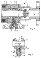
- FIG. 1 shows an axial section through one end of a linear valve, namely a so-called coaxial valve.
- the valve includes a housing 1, which is generally cylindrical in shape about.
- a valve interior 2 is formed, in which a valve seat body 3 is housed.
- the valve seat body 3 has a valve seat 4 on its left side in FIG.
- a valve closing body 5 is arranged displaceably in the form of a control tube in its own longitudinal direction.
- a magnet 6 which is connected to the control tube 5, and a magnetic coil 7, which is arranged fixed to the housing.
- the valve seat 4 associated with the end of the valve closing body 5 rests in the closed state on this valve seat 4.
- the control tube 5 By actuating the valve drive, the control tube 5 can be lifted off the valve seat 5. Then the medium to be controlled flows through the interior of the control tube 5 past the valve seat 4 through the outlet 8 seen on the right in FIG. 1.
- This is the normal function of a coaxial valve.
- a sleeve 9 On the valve closing body 5, a sleeve 9 is attached, which is acted upon by a pressure spring 10 supported on the valve housing 1 against a connected to the valve closing body 5 snap ring 11.
- the spring 10 is arranged in an annular space between the sleeve 9 and the valve closing body 5. It may be in the spring 10 both a spring acting on the valve in a normally closed position, as well as to a working independently of the valve spring whose sole purpose is to apply the sleeve 9 against the snap ring 11.
- the sleeve 9 has on its outer side a circumferential groove 12, which serves to remove the movement of the closing body 5.
- a screw insert 14 is screwed, in which a transmission element 15 is mounted.
- the transmission element 15 engages with its directed into the interior of the valve housing 1 free end in the circumferential annular groove 12 a.
- this movement is transmitted by means of the transmission element 15 through the wall 13 of the valve housing 1 to the outside.
- the threaded insert has a stepped cylindrical sleeve. At the end directed into the interior of the housing 1, the threaded insert has an outer thread 16 on its outer side.
- the External thread 16 is not quite enough to a shoulder 17, which is formed on an increase in diameter of the screw 14. In the area between the external thread 16 and the shoulder 17 there is room for an O-ring 18.
- the now smooth outer cylindrical part of the screw insert extends to the end of the screw insert, where on the outside of a circumferential rib 19 is formed.
- the screw insert is inserted into the interior of a cage 20, to such an extent that the rib 19 prevents further pushing through an opening of the cage 20.
- a receiving sleeve 21 is inserted, which is acted upon by means of cylinder head bolts 22 against the cylindrical sleeve of the screw 14 and against the cage 20.
- the receiving sleeve 21 has, perpendicular to its longitudinal direction, an opening 23 passing through its wall and, in extension thereof, a further through opening 24 with a slightly larger diameter.
- a first partial shell 26 is inserted in the interior of the screw insert 14, resting on a step 25, a first partial shell 26 is inserted.
- This sub-shell 26 has a part-spherical shoulder 25 facing away from the bearing surface.
- a spherical bearing element 27 is inserted, which is applied against the mentioned part-spherical bearing surface of the partial shell 26.
- the bearing element 27 is surrounded by an O-ring 28.
- a second half-shell 29 is inserted from the opposite side of the O-ring, which now comes to rest against the O-ring 28 and the ball 27.
- the bearing element 27 is pushed onto a rod 30 and fixedly connected to this rod 30. This can be done for example by gluing. Thereby, a two-armed lever is formed, which can be pivoted about the center of the bearing member 27, because of the spherical shape to any number of axes.
- the lower in Figure 2 in the interior of the valve housing 1 into the end of this rod 30 engages in the already mentioned circumferential groove 12 a.
- the opposite end 31 of the transmission element arranged inside the receiving sleeve 21 moves in the opposite direction. This movement of the end 31 can be exploited to actuate either optically detectable displays or electrical switches.
- an electrical switch can be inserted in the receiving sleeve 21, depending on the type of valve.
- an electrical switch can be inserted in the receiving sleeve 21.
- Each microswitch 32 is first screwed into an adapter sleeve 33, with an external thread which engages in a corresponding internal thread of the adapter sleeve 33.
- the adapter sleeves 33 are then fixed by means of radially extending threaded pins 34 in its axial position.
- the end 31 of the transmission element can then actuate one of the two microswitches 32.
- the circuit opened or closed by the actuation of the microswitch can be used for a wide variety of purposes, for example as a safety device, as a display device, as a measuring device in comparison to the time when the magnet was turned on, or in any other way.
- Figure 3 shows an arrangement in which in the receiving sleeve 21, a slider 35 is moved.
- the threaded pins 34 are therefore missing here.
- the slide 35 is displaced by the fact that the end 31 of the rod 30 engages in a transverse bore 36.
- the two axial ends of the slider 35 may have an optically detectable mark, for example, the one end face in red and the other in green. Since the axial length of the slider 35 is slightly smaller than the axial length of the receiving sleeve 21, then only one end face is visible, which then reveals the mark.
- a slider 35 made of certain material may be used to actuate inductive switches 37, as indicated in FIG. Figure 4 shows a plan view of an arrangement as shown in Figures 2 and 3 from the side. Here is the cage to see above. The displacement of the slider 35 is done from left to right or from right to left.
- a slider 35 as shown in Figure 3, could also serve with appropriate cross holes to open and / or close the light barriers, in order to realize in this way another type of non-contact switch.
Landscapes
- Engineering & Computer Science (AREA)
- General Engineering & Computer Science (AREA)
- Mechanical Engineering (AREA)
- Physics & Mathematics (AREA)
- Fluid Mechanics (AREA)
- Indication Of The Valve Opening Or Closing Status (AREA)
- Control Of Eletrric Generators (AREA)
- Electrical Discharge Machining, Electrochemical Machining, And Combined Machining (AREA)
Description
- Die Erfindung geht aus von einem Linearventil, bei dem in einem Ventilgehäuse ein Ventilsitz und ein mit diesem zusammenwirkender Ventilschließkörper angeordnet ist. Zum Antrieb derartiger Ventile dienen beispielsweise Magnete, oder auch pneumatische oder hydraulische Antriebe. Es ist zwar möglich, den Steuerzustand des Ventils abzufragen, das heißt den Zustand des Antriebs des Ventils. Damit wird aber noch keine eindeutige Aussage über den tatsächlichen Zustand des Ventils geschaffen.
- Es ist bereits ein Durchgangsventil mit Stellungsanzeiger bekannt (DE-A-2020194), bei dem der Ventilschließkörper im Endbereich seines Bewegungsweges einen durch die Wand des Ventilgehäuses hindurch ragenden Hebel verkippt, der in verkipptem Zustand einen elektrischen Schalter betätigt. Der elektrische Schalter schaltet zwischen zwei Lampen um.
- Bei einem weiteren Linearventil (WO94/27069) ist in einem Flansch des Ventilschließkörpers ein Stift eingeschraubt, der durch eine abgedichtete Bohrung des Ventilgehäuses hindurch ragt und in seiner eigenen Längsrichtung verschoben werden kann. Er betätigt einen elektrischen Schalter.
- Weiterhin ist es bekannt, zur Anzeige eines Ventils einen durch die Gehäusewandung ragenden Hebel zu verwenden, der in einer Membran schwenkbar gelagert ist (US-A 2509504).
- Weiterhin bekannt ist ein Ventil (US-6152173), bei dem an der stromabgewandten Seite des Ventilschließkörpers ein Ende eines zweiarmigen verkippbaren Hebels angreift. Dieser Hebel ist federbeaufschlagt, damit er der Bewegung des Ventilschließkörpers folgen kann. Er ist mit einem Kugelabschnitt in einer Lagerung gelagert.
- Der Erfindung liegt die Aufgabe zu Grunde, eine Möglichkeit zu schaffen, den tatsächlichen Schließzustand des Ventils anzeigen und/oder abfragen zu können.
- Zur Lösung dieser Aufgabe schlägt die Erfindung ein Ventil mit den im Anspruch 1 genannten Merkmalen vor. Weiterbildungen der Erfindung sind Gegenstand von Unteransprüchen.
Durch die Erfindung wird es möglich, den tatsächlichen Schließzustand des Ventils, also die gewünschte Endstellung in Form eines Schließzustandes oder eines Öffnungszustandes, unabhängig davon erkennen zu können, ob das Ventil den Vorgaben des Antriebs gefolgt ist oder nicht. Es wird ebenfalls möglich, beispielsweise feststellen zu können, welche Zeit zwischen dem Steuerimpuls zum Schließen bzw.
Öffnen des Ventils und dem Erreichen des Schließzustandes beziehungsweise Öffnungszustandes verstreicht. - Bei der Anzeigeeinrichtung kann es sich um eine beliebig gestaltete Einrichtung handeln, mit deren Hilfe der Zustand angezeigt werden kann. Insbesondere kann es sich dabei um eine Einrichtung mit einem Endschalter handeln, der nicht nur zum Einschalten einer Anzeige, sondern beispielsweise auch zum Auslösen und/oder Beenden eines bestimmten dem gewünschten Zustand des Ventils zugeordneten Ereignisses ausgenutzt werden kann.
- In Weiterbildung der Erfindung kann vorgesehen sein, dass die Anzeigeeinrichtung außerhalb des Ventilraumes, vorzugsweise außerhalb des Ventilgehäuses angeordnet ist. Die Einrichtung stört den Betrieb des Ventils nicht.
- Erfindungsgemäß ist in Weiterbildung vorgesehen, dass die Anzeigeeinrichtung mit Hilfe eines durch die Wand des Ventilgehäuses hindurch greifenden Übertragungselements mechanisch betätigbar ist. Es kann dafür gesorgt werden, dass die Art, wie das Übertragungselement durch die Wand des Ventilgehäuses hindurch greift, in einer abgedichteten Weise erfolgt, so dass keinerlei Beeinträchtigungen der Funktion des Ventils zu befürchten sind.
- Insbesondere kann vorgesehen sein, dass die Anzeigeeinrichtung ohne eine Unterbrechung des Betriebszustandes des Ventils austauschbar angeordnet und ausgebildet ist. Sollte einmal ein Schalter oder dergleichen ausfallen, so kann dieser ausgetauscht werden, ohne dass das Ventil oder die Installation, zu der das Ventil gehört, beispielsweise drucklos gemacht werden müsste.
- Bei dem eingangs erwähnten Endschalter kann es sich um einen elektrischen Schalter, einen berührungsfrei arbeitenden Schalter, beispielsweise auch einen optisch betätigbaren Schalter handeln.
- Zusätzlich oder alternativ hierzu kann vorgesehen sein, dass die Anzeigeeinrichtung eine optisch erkennbare Markierung aufweist. Hier kann im Notfall der Benutzer sogar ohne weitere Hilfsmittel ablesen, ob das Ventil geöffnet oder geschlossen ist.
- Das Übertragungselement weist einen verkippbar gelagerten insbesondere zweiarmigen Hebel auf, der einerseits von dem Ventilschließkörper beaufschlagt wird und andererseits an dem Schalter angreift.
- Zur Lagerung des Hebels ist ein mit diesem verbundenes Lagerelement zwischen Teilschalen eingespannt. Das Lagerelement ist eine Kugel, so dass die Bewegung des Übertragungselements ein Verschwenken um viele Achsen ist.
- Es ist erfindungsgemäß vorgesehen, dass zwischen zwei Halbschalen ein Dichtelement vorgesehen ist, das das Lagerelement umgibt. Es dichtet sowohl das Lagerelement als auch die beiden Halbschalen gegeneinander und gegen das Gehäuse ab, in dem die Lagerung angeordnet ist.
- Insbesondere kann vorgesehen sein, dass die Lagerung des Übertragungselements in einem Schraubeinsatz angeordnet ist.
Weitere Merkmale, Einzelheiten und Vorzüge der Erfindung ergeben sich aus der folgenden Beschreibung bevorzugter Ausführungsformen der Erfindung sowie anhand der Zeichnung. Hierbei zeigen: - Figur 1
- einen Teilschnitt durch ein Ende eines Linearventils mit einer Anzeigeeinrichtung nach der Erfindung;
- Figur 2
- in vergrößertem Maßstab das Anzeigeelement mit einem Übertragungselement;
- Figur 3
- eine gegenüber Figur 2 abgeänderte Ausführungsform;
- Figur 4
- eine weitere Ausführungsform der Anzeigeeinrichtung nach der Erfindung.
- Figur 1 zeigt einen Axialschnitt durch ein Ende eines Linearventils, nämlich eines sogenannten Koaxialventils. Das Ventil enthält ein Gehäuse 1, das im Großen und Ganzen etwa zylindrisch ausgebildet ist. In dem Gehäuse 1 ist ein Ventilinnenraum 2 gebildet, in dem ein Ventilsitzkörper 3 untergebracht ist. Der Ventilsitzkörper 3 weist auf seiner einen in Figur 1 linken Seite einen Ventilsitz 4 auf. In dem Innenraum des Gehäuses ist ein Ventilschließkörper 5 in Form eines Steuerrohrs in seiner eigenen Längsrichtung verschiebbar angeordnet. Zum Antrieb bzw. zur Verschiebung des Ventilschließkörpers 5 dient ein Magnet 6, der mit dem Steuerrohr 5 verbunden ist, und eine Magnetspule 7, die gehäusefest angeordnet ist. Das dem Ventilsitz 4 zugeordnete Ende des Ventilschließkörpers 5 ruht im Schließzustand auf diesem Ventilsitz 4 auf. Durch Betätigen des Ventilantriebs kann das Steuerrohr 5 von dem Ventilsitz 5 abgehoben werden. Dann fließt das zu steuernde Medium durch das Innere des Steuerrohrs 5 an dem Ventilsitz 4 vorbei durch den rechts in Figur 1 zu sehenden Auslass 8. Dies ist die normale Funktion eines Koaxialventils.
An dem Ventilschließkörper 5 ist eine Hülse 9 angebracht, die von einer sich am Ventilgehäuse 1 abstützenden Druckfeder 10 gegen einen mit dem Ventilschließkörper 5 verbundenen Sprengring 11 beaufschlagt wird. Die Feder 10 ist in einem ringförmigen Zwischenraum zwischen der Hülse 9 und dem Ventilschließkörper 5 angeordnet. Es kann sich bei der Feder 10 sowohl um eine Feder handeln, die das Ventil in eine normalerweise geschlossene Stellung beaufschlagt, als auch um eine unabhängig von dem Ventil arbeitende Feder, deren einziger Zweck es ist, die Hülse 9 gegen den Sprengring 11 zu beaufschlagen. - Die Hülse 9 weist an ihrer Außenseite eine umlaufende Nut 12 auf, die dazu dient, die Bewegung des Schließkörpers 5 abzunehmen.
- In der zylindrischen Mantelwand 13 des Ventilgehäuses 1 ist ein Schraubeinsatz 14 eingeschraubt, in dem ein Übertragungselement 15 gelagert ist. Das Übertragungselement 15 greift mit seinem in das Innere des Ventilgehäuse 1 gerichteten freien Ende in die umlaufende Ringnut 12 ein. Bei einer Bewegung der Hülse 9, verursacht durch eine Bewegung des Ventilschließkörpers 5, wird diese Bewegung mit Hilfe des Übertragungselements 15 durch die Wand 13 des Ventilgehäuses 1 nach außen übertragen.
- Einzelheiten des Übertragungselements 15 und des Schraubeinsatzes 14 ergeben sich aus der Figur 2, auf die jetzt im folgenden Bezug genommen wird.
- Der Schraubeinsatz weist eine abgestufte zylindrische Hülse auf. An dem in das Innere des Gehäuses 1 gerichteten Ende weist der Schraubeinsatz an seiner Außenseite ein Außengewinde 16 auf. Das Außengewinde 16 reicht nicht ganz bis zu einer Schulter 17, die an einer Durchmesservergrößerung des Schraubeinsatzes 14 gebildet ist. Im Bereich zwischen dem Außengewinde 16 und der Schulter 17 ist Platz für einen O-Ring 18. Der jetzt glatte außen zylindrische Teil des Schraubeinsatzes reicht bis zum Ende des Schraubeinsatzes, wo an der Außenseite eine umlaufende Rippe 19 gebildet ist.
- Der Schraubeinsatz ist in das Innere eines Käfigs 20 eingesetzt, und zwar so weit, dass die Rippe 19 ein weiteres Durchschieben durch eine Öffnung des Käfigs 20 verhindert. In dem Käfig ist eine Aufnahmehülse 21 eingesetzt, die mit Hilfe von Zylinderkopfschrauben 22 gegen die zylindrische Hülse des Schraubeinsatzes 14 und gegen den Käfig 20 beaufschlagt wird. Die Aufnahmehülse 21 weist senkrecht zu ihrer Längsrichtung eine durch ihre Wand hindurch gehende Öffnung 23 und in Verlängerung zu dieser eine weitere durchgehende Öffnung 24 mit einem etwas größeren Durchmesser auf.
- In dem Innenraum des Schraubeinsatzes 14 ist, auf einer Stufe 25 aufliegend, eine erste Teilschale 26 eingesetzt. Diese Teilschale 26 weist eine teilkugelförmige der Schulter 25 abgewandte Lagerfläche auf. In den Innenraum des Schraubeinsatzes wird ein kugelförmiges Lagerelement 27 eingeschoben, das gegen die erwähnte teilkugelförmige Lagerfläche der Teilschale 26 angelegt wird. Das Lagerelement 27 wird von einem O-Ring 28 umgeben. Anschließend wird von der gegenüberliegenden Seite des O-Rings eine zweite Halbschale 29 eingeschoben, die jetzt gegen den O-Ring 28 und die Kugel 27 zur Anlage kommt. Durch Festziehen der Aufnahmehülse 21 mit Hilfe der Schrauben 22 wird die zweite Halbschale 29 gegen das Lagerelement 27 beaufschlagt und festgedrückt. Die Abmessungen des Innenraums des Schraubeinsatzes 14, der Halbschalen 26 und 29 und des Lagerelements 27 sind so aufeinander abgestimmt, dass die Kugel 27 sich noch mit der erforderlichen Kraft verdrehen lässt, andererseits aber die gewünschte Dichtigkeit gegeben ist.
- Das Lagerelement 27 ist auf eine Stange 30 aufgeschoben und mit dieser Stange 30 fest verbunden. Dies kann beispielsweise durch eine Klebung geschehen. Dadurch wird ein zweiarmiger Hebel gebildet, der um den Mittelpunkt des Lagerelements 27 verschwenkt werden kann, und zwar wegen der Kugelform um beliebig viele Achsen. Das in Figur 2 untere in das Innere des Ventilgehäuses 1 hinein gerichtete Ende dieser Stange 30 greift in die bereits erwähnte umlaufende Nut 12 ein. Dadurch bewegt sich das entgegengesetzte im Inneren der Aufnahmehülse 21 angeordnete Ende 31 des Übertragungselements in umgekehrter Richtung. Diese Bewegung des Endes 31 kann dazu ausgenutzt werden, entweder optisch wahrnehmbare Anzeigen oder elektrische Schalter zu betätigen.
- In die Aufnahmehülse 21 kann, je nach der Art des Ventils, ein elektrischer Schalter eingeschoben werden. Hierzu wird nochmals auf die Figur 1 verwiesen. In der schematischen Darstellung der Figur 1 sind zwei Mikroschalter 32 in der Aufnahmehülse 21 angeordnet. Jeder Mikroschalter 32 ist zunächst in eine Adapterhülse 33 eingeschraubt, und zwar mit einem Außengewinde, das in ein entsprechendes Innengewinde der Adapterhülse 33 eingreift. Die Adapterhülsen 33 sind dann mit Hilfe von radial verlaufenden Gewindestiften 34 in ihrer axialen Position festgelegt. Das Ende 31 des Übertragungselements kann dann einen der beiden Mikroschalter 32 betätigen.
- Der durch das Betätigen des Mikroschalters geöffnete oder geschlossene Stromkreis kann für die unterschiedlichsten Zwecke verwendet werden, beispielsweise als Sicherheitseinrichtung, als Anzeigeeinrichtung, als Messeinrichtung im Vergleich zu dem Zeitpunkt, zu dem der Magnet eingeschaltet wurde, oder in sonstiger beliebiger Weise.
- Die durch die Bewegung des Übertragungselements entstehende Verschiebung des Endes 31 der Stange 30 kann auch für andere Zwecke ausgenutzt werden. So zeigt beispielsweise die Figur 3 eine Anordnung, bei der in der Aufnahmehülse 21 ein Schieber 35 verschoben wird. Die Gewindestifte 34 fehlen hier also. Der Schieber 35 wird dadurch verschoben, dass das Ende 31 der Stange 30 in eine Querbohrung 36 eingreift. Die beiden axialen Enden des Schiebers 35 können eine optisch wahrnehmbare Markierung aufweisen, beispielsweise die eine Stirnfläche in Rot und die andere in Grün. Da die axiale Länge des Schiebers 35 etwas kleiner ist als die axiale Länge der Aufnahmehülse 21, ist dann immer nur eine Stirnfläche sichtbar, die dann die Markierung erkennen lässt.
- Die Verschiebung eines solchen Schiebers 35 kann auch dazu ausgenutzt werden, berührungsfrei elektrische Schaltvorgänge auszulösen. Beispielsweise kann ein Schieber 35, der aus bestimmten Material besteht, dazu verwendet werden, induktive Schalter 37 zu betätigen, wie dies in Figur 4 angedeutet ist. Figur 4 zeigt eine Aufsicht auf eine Anordnung, wie sie in Figur 2 und 3 von der Seite gezeigt ist. Hier ist der Käfig oben zu sehen. Die Verschiebung des Schiebers 35 geschieht von links nach rechts beziehungsweise von rechts nach links.
- Ein Schieber 35, wie er bei der Figur 3 dargestellt ist, könnte mit entsprechenden Querbohrungen auch dazu dienen, Lichtschranken zu öffnen und/oder zu schließen, um auf diese Weise eine andere Art eines berührungsfreien Schalters zu verwirklichen.
Claims (8)
- Linearventil, mit1.1 einem Ventilgehäuse (1),1.2 einem in dem Ventilgehäuse (1) angeordneten Ventilsitz (4),1.3 einem in dem Ventilgehäuse (1) angeordneten, mit dem Ventilsitz (4) zusammenwirkenden Ventilschließkörper (5), sowie mit1.4 einer Einrichtung zum Anzeigen des Schließzustandes des Ventils, die1.4.1 mechanisch durch den Ventilschließkörper (5) und1.4.2 mit Hilfe eines durch die Wand (13) des Ventilgehäuses (1) hindurch greifenden Übertragungselements (15) betätigbar ist, das1.4.3 einen verkippbar gelagerten insbesondere zweiarmigen Hebel aufweist,1.4.4 zu dessen Lagerung ein mit diesem verbundenes als Kugel ausgebildetes Lagerelement (27) zwischen Teitschalen (26, 29) eingespannt ist, die1.4.5 teilkugelförmige Lagerflächen aufweisen, dadurch gekennzeichnet, dass1.5 zwischen den zwei Teilschalen (26, 29) ein das Lagerelement (27) umgebendes Dichtelement (28) vorgesehen ist.
- Ventil nach Anspruch 1, bei dem die Einrichtung einen Endschalter aufweist.
- Ventil nach Anspruch 1 oder 2, bei dem die Anzeigeeinrichtung außerhalb des Ventilinnenraums (2), vorzugsweise außerhalb des Ventilgehäuses (1) angeordnet ist.
- Ventil nach einem der vorhergehenden Ansprüche, bei dem die Anzeigeeinrichtung ohne Unterbrechung des Betriebszustandes des Ventils austauschbar angeordnet ist.
- Ventil nach einem der Ansprüche 2 bis 4, bei dem der Endschalter ein elektrischer Schalter (32) ist.
- Ventil nach einem der Ansprüche 2 bis 5, bei dem der Endschalter ein berührungsfrei arbeitender Schalter ist.
- Ventil nach einem der vorhergehenden Ansprüche, bei dem die Anzeigeeinrichtung eine optisch erkennbare Markierung aufweist.
- Ventil nach einem der vorhergehenden Ansprüche, bei dem die Lagerung des Übertragungselements (15) in einem Schraubeinsatz (14) angeordnet ist.
Applications Claiming Priority (2)
| Application Number | Priority Date | Filing Date | Title |
|---|---|---|---|
| DE10227549 | 2002-06-14 | ||
| DE10227549A DE10227549A1 (de) | 2002-06-14 | 2002-06-14 | Mechanischer Endschalter |
Publications (2)
| Publication Number | Publication Date |
|---|---|
| EP1371886A1 EP1371886A1 (de) | 2003-12-17 |
| EP1371886B1 true EP1371886B1 (de) | 2006-05-31 |
Family
ID=29557862
Family Applications (1)
| Application Number | Title | Priority Date | Filing Date |
|---|---|---|---|
| EP03012987A Expired - Lifetime EP1371886B1 (de) | 2002-06-14 | 2003-06-07 | Endschalter |
Country Status (3)
| Country | Link |
|---|---|
| EP (1) | EP1371886B1 (de) |
| AT (1) | ATE328228T1 (de) |
| DE (2) | DE10227549A1 (de) |
Families Citing this family (2)
| Publication number | Priority date | Publication date | Assignee | Title |
|---|---|---|---|---|
| DE102005012851A1 (de) * | 2005-03-17 | 2006-09-28 | müller co-ax ag | Coaxialventil mit selbstdichtendem Ventilsitz |
| DE102014018438A1 (de) | 2014-12-12 | 2016-06-16 | Daimler Ag | Ventileinrichtung zum Aufteilen eines Massenstroms eines Fluids sowie Wärmerückgewinnungsvorrichtung mit einer solchen Ventileinrichtung |
Family Cites Families (5)
| Publication number | Priority date | Publication date | Assignee | Title |
|---|---|---|---|---|
| US2509504A (en) * | 1945-11-06 | 1950-05-30 | Garrett Corp Aires Mfg Company | Cooler failure automatic by-pass valve |
| US3566907A (en) * | 1969-04-25 | 1971-03-02 | Vapor Corp | Inline valve position indicator |
| CH688833A5 (de) * | 1993-05-19 | 1998-04-15 | Fischer Georg Rohrleitung | Ventil. |
| DE19729553A1 (de) * | 1997-07-10 | 1999-01-14 | Aws Apparatebau Arnold Gmbh | Koaxialventil mit Rückschlagventil |
| US6152173A (en) * | 1999-07-28 | 2000-11-28 | Val-Matic Valve And Manufacturing Corp. | Position indicating check valve |
-
2002
- 2002-06-14 DE DE10227549A patent/DE10227549A1/de not_active Withdrawn
-
2003
- 2003-06-07 DE DE50303547T patent/DE50303547D1/de not_active Expired - Lifetime
- 2003-06-07 EP EP03012987A patent/EP1371886B1/de not_active Expired - Lifetime
- 2003-06-07 AT AT03012987T patent/ATE328228T1/de not_active IP Right Cessation
Also Published As
| Publication number | Publication date |
|---|---|
| EP1371886A1 (de) | 2003-12-17 |
| DE50303547D1 (de) | 2006-07-06 |
| DE10227549A1 (de) | 2003-12-24 |
| ATE328228T1 (de) | 2006-06-15 |
Similar Documents
| Publication | Publication Date | Title |
|---|---|---|
| DE60033342T2 (de) | Wegeventil mit Positionsermittlung | |
| EP1759176B1 (de) | Strömungssensor | |
| EP3321643B1 (de) | Positionssensor und stellgerät mit positionssensor | |
| DE3001458A1 (de) | Rueckschlagventil mit selbstanzeige fuer fliessfaehige, unter druck stehende medien | |
| DE102006049724A1 (de) | Ventilanordnung mit Positionssensor | |
| EP1887283A1 (de) | Gasventil und Verfahren zur Ansteuerung eines Gasventils | |
| EP0397915A2 (de) | Pneumatisches Stellglied | |
| EP1344949A2 (de) | Ventileinrichtung für Stellzylinder | |
| WO2012080055A2 (de) | Gasventileinheit mit einer betätigungsmechanik für ein magnetventil | |
| EP2405166A2 (de) | Magnetimpulsventil | |
| DE102013010432A1 (de) | Thermostatisch gesteuertes Ventil, insbesondere Heizkörperventil | |
| DE102004028759B4 (de) | Strömungssensor | |
| EP2211247A2 (de) | Druckminderer für Gase | |
| EP1552199B1 (de) | Gashahn mit einem elektromagnetischen sicherheitsventil | |
| DE10227549A1 (de) | Mechanischer Endschalter | |
| DE3102232A1 (de) | Magnetventil | |
| DE4101733A1 (de) | Sicherheitseinsatz fuer druckgas und fluessiggas | |
| DE10121770A1 (de) | Elektromagnetische Stelleinrichtung | |
| WO2003106873A1 (de) | Absperrorgan | |
| EP0056494B1 (de) | Thermostat zum Betätigen eines Steuerorgans | |
| AT520721B1 (de) | Ventilvorrichtung zum Absperren und Öffnen eines Gasstromes zu einem Analysator einer Gasmessanlage | |
| DE102015202747B4 (de) | Absperrarmatur mit Sensor | |
| DE102006058398B4 (de) | Steuereinheit für ein Ventil, insbesondere für ein doppelt dichtendes Ventil | |
| DE10031873A1 (de) | Hydraulisches Ventil | |
| DE10245766A1 (de) | Absperrorgan |
Legal Events
| Date | Code | Title | Description |
|---|---|---|---|
| PUAI | Public reference made under article 153(3) epc to a published international application that has entered the european phase |
Free format text: ORIGINAL CODE: 0009012 |
|
| AK | Designated contracting states |
Kind code of ref document: A1 Designated state(s): AT BE BG CH CY CZ DE DK EE ES FI FR GB GR HU IE IT LI LU MC NL PT RO SE SI SK TR |
|
| AX | Request for extension of the european patent |
Extension state: AL LT LV MK |
|
| 17P | Request for examination filed |
Effective date: 20040616 |
|
| 17Q | First examination report despatched |
Effective date: 20040720 |
|
| AKX | Designation fees paid |
Designated state(s): AT BE BG CH CY CZ DE DK EE ES FI FR GB GR HU IE IT LI LU MC NL PT RO SE SI SK TR |
|
| GRAP | Despatch of communication of intention to grant a patent |
Free format text: ORIGINAL CODE: EPIDOSNIGR1 |
|
| GRAS | Grant fee paid |
Free format text: ORIGINAL CODE: EPIDOSNIGR3 |
|
| GRAA | (expected) grant |
Free format text: ORIGINAL CODE: 0009210 |
|
| AK | Designated contracting states |
Kind code of ref document: B1 Designated state(s): AT BE BG CH CY CZ DE DK EE ES FI FR GB GR HU IE IT LI LU MC NL PT RO SE SI SK TR |
|
| PG25 | Lapsed in a contracting state [announced via postgrant information from national office to epo] |
Ref country code: RO Free format text: LAPSE BECAUSE OF FAILURE TO SUBMIT A TRANSLATION OF THE DESCRIPTION OR TO PAY THE FEE WITHIN THE PRESCRIBED TIME-LIMIT Effective date: 20060531 Ref country code: CZ Free format text: LAPSE BECAUSE OF FAILURE TO SUBMIT A TRANSLATION OF THE DESCRIPTION OR TO PAY THE FEE WITHIN THE PRESCRIBED TIME-LIMIT Effective date: 20060531 Ref country code: GB Free format text: LAPSE BECAUSE OF FAILURE TO SUBMIT A TRANSLATION OF THE DESCRIPTION OR TO PAY THE FEE WITHIN THE PRESCRIBED TIME-LIMIT Effective date: 20060531 Ref country code: NL Free format text: LAPSE BECAUSE OF FAILURE TO SUBMIT A TRANSLATION OF THE DESCRIPTION OR TO PAY THE FEE WITHIN THE PRESCRIBED TIME-LIMIT Effective date: 20060531 Ref country code: IE Free format text: LAPSE BECAUSE OF FAILURE TO SUBMIT A TRANSLATION OF THE DESCRIPTION OR TO PAY THE FEE WITHIN THE PRESCRIBED TIME-LIMIT Effective date: 20060531 Ref country code: SI Free format text: LAPSE BECAUSE OF FAILURE TO SUBMIT A TRANSLATION OF THE DESCRIPTION OR TO PAY THE FEE WITHIN THE PRESCRIBED TIME-LIMIT Effective date: 20060531 Ref country code: SK Free format text: LAPSE BECAUSE OF FAILURE TO SUBMIT A TRANSLATION OF THE DESCRIPTION OR TO PAY THE FEE WITHIN THE PRESCRIBED TIME-LIMIT Effective date: 20060531 Ref country code: FI Free format text: LAPSE BECAUSE OF FAILURE TO SUBMIT A TRANSLATION OF THE DESCRIPTION OR TO PAY THE FEE WITHIN THE PRESCRIBED TIME-LIMIT Effective date: 20060531 |
|
| REG | Reference to a national code |
Ref country code: GB Ref legal event code: FG4D Free format text: NOT ENGLISH Ref country code: CH Ref legal event code: EP Ref country code: CH Ref legal event code: NV Representative=s name: TROESCH SCHEIDEGGER WERNER AG |
|
| REG | Reference to a national code |
Ref country code: IE Ref legal event code: FG4D Free format text: LANGUAGE OF EP DOCUMENT: GERMAN |
|
| PG25 | Lapsed in a contracting state [announced via postgrant information from national office to epo] |
Ref country code: MC Free format text: LAPSE BECAUSE OF NON-PAYMENT OF DUE FEES Effective date: 20060630 Ref country code: BE Free format text: LAPSE BECAUSE OF NON-PAYMENT OF DUE FEES Effective date: 20060630 |
|
| REF | Corresponds to: |
Ref document number: 50303547 Country of ref document: DE Date of ref document: 20060706 Kind code of ref document: P |
|
| PG25 | Lapsed in a contracting state [announced via postgrant information from national office to epo] |
Ref country code: DK Free format text: LAPSE BECAUSE OF FAILURE TO SUBMIT A TRANSLATION OF THE DESCRIPTION OR TO PAY THE FEE WITHIN THE PRESCRIBED TIME-LIMIT Effective date: 20060831 Ref country code: SE Free format text: LAPSE BECAUSE OF FAILURE TO SUBMIT A TRANSLATION OF THE DESCRIPTION OR TO PAY THE FEE WITHIN THE PRESCRIBED TIME-LIMIT Effective date: 20060831 |
|
| PG25 | Lapsed in a contracting state [announced via postgrant information from national office to epo] |
Ref country code: ES Free format text: LAPSE BECAUSE OF FAILURE TO SUBMIT A TRANSLATION OF THE DESCRIPTION OR TO PAY THE FEE WITHIN THE PRESCRIBED TIME-LIMIT Effective date: 20060911 |
|
| PG25 | Lapsed in a contracting state [announced via postgrant information from national office to epo] |
Ref country code: PT Free format text: LAPSE BECAUSE OF FAILURE TO SUBMIT A TRANSLATION OF THE DESCRIPTION OR TO PAY THE FEE WITHIN THE PRESCRIBED TIME-LIMIT Effective date: 20061031 |
|
| NLV1 | Nl: lapsed or annulled due to failure to fulfill the requirements of art. 29p and 29m of the patents act | ||
| ET | Fr: translation filed | ||
| GBV | Gb: ep patent (uk) treated as always having been void in accordance with gb section 77(7)/1977 [no translation filed] |
Effective date: 20060531 |
|
| REG | Reference to a national code |
Ref country code: IE Ref legal event code: FD4D |
|
| PLBE | No opposition filed within time limit |
Free format text: ORIGINAL CODE: 0009261 |
|
| STAA | Information on the status of an ep patent application or granted ep patent |
Free format text: STATUS: NO OPPOSITION FILED WITHIN TIME LIMIT |
|
| 26N | No opposition filed |
Effective date: 20070301 |
|
| PG25 | Lapsed in a contracting state [announced via postgrant information from national office to epo] |
Ref country code: AT Free format text: LAPSE BECAUSE OF NON-PAYMENT OF DUE FEES Effective date: 20060607 |
|
| BERE | Be: lapsed |
Owner name: MULLER CO-AX A.G. Effective date: 20060630 |
|
| PG25 | Lapsed in a contracting state [announced via postgrant information from national office to epo] |
Ref country code: GR Free format text: LAPSE BECAUSE OF FAILURE TO SUBMIT A TRANSLATION OF THE DESCRIPTION OR TO PAY THE FEE WITHIN THE PRESCRIBED TIME-LIMIT Effective date: 20060901 |
|
| PG25 | Lapsed in a contracting state [announced via postgrant information from national office to epo] |
Ref country code: EE Free format text: LAPSE BECAUSE OF FAILURE TO SUBMIT A TRANSLATION OF THE DESCRIPTION OR TO PAY THE FEE WITHIN THE PRESCRIBED TIME-LIMIT Effective date: 20060531 Ref country code: BG Free format text: LAPSE BECAUSE OF FAILURE TO SUBMIT A TRANSLATION OF THE DESCRIPTION OR TO PAY THE FEE WITHIN THE PRESCRIBED TIME-LIMIT Effective date: 20060831 |
|
| PG25 | Lapsed in a contracting state [announced via postgrant information from national office to epo] |
Ref country code: HU Free format text: LAPSE BECAUSE OF FAILURE TO SUBMIT A TRANSLATION OF THE DESCRIPTION OR TO PAY THE FEE WITHIN THE PRESCRIBED TIME-LIMIT Effective date: 20061201 Ref country code: TR Free format text: LAPSE BECAUSE OF FAILURE TO SUBMIT A TRANSLATION OF THE DESCRIPTION OR TO PAY THE FEE WITHIN THE PRESCRIBED TIME-LIMIT Effective date: 20060531 Ref country code: LU Free format text: LAPSE BECAUSE OF NON-PAYMENT OF DUE FEES Effective date: 20060607 |
|
| PG25 | Lapsed in a contracting state [announced via postgrant information from national office to epo] |
Ref country code: CY Free format text: LAPSE BECAUSE OF FAILURE TO SUBMIT A TRANSLATION OF THE DESCRIPTION OR TO PAY THE FEE WITHIN THE PRESCRIBED TIME-LIMIT Effective date: 20060531 |
|
| PGFP | Annual fee paid to national office [announced via postgrant information from national office to epo] |
Ref country code: IT Payment date: 20140625 Year of fee payment: 12 Ref country code: CH Payment date: 20140620 Year of fee payment: 12 |
|
| PGFP | Annual fee paid to national office [announced via postgrant information from national office to epo] |
Ref country code: FR Payment date: 20140617 Year of fee payment: 12 |
|
| PG25 | Lapsed in a contracting state [announced via postgrant information from national office to epo] |
Ref country code: IT Free format text: LAPSE BECAUSE OF NON-PAYMENT OF DUE FEES Effective date: 20150607 |
|
| REG | Reference to a national code |
Ref country code: CH Ref legal event code: PL |
|
| REG | Reference to a national code |
Ref country code: FR Ref legal event code: ST Effective date: 20160229 |
|
| PG25 | Lapsed in a contracting state [announced via postgrant information from national office to epo] |
Ref country code: CH Free format text: LAPSE BECAUSE OF NON-PAYMENT OF DUE FEES Effective date: 20150630 Ref country code: LI Free format text: LAPSE BECAUSE OF NON-PAYMENT OF DUE FEES Effective date: 20150630 |
|
| PG25 | Lapsed in a contracting state [announced via postgrant information from national office to epo] |
Ref country code: FR Free format text: LAPSE BECAUSE OF NON-PAYMENT OF DUE FEES Effective date: 20150630 |
|
| REG | Reference to a national code |
Ref country code: DE Ref legal event code: R081 Ref document number: 50303547 Country of ref document: DE Owner name: MUELLER CO-AX GMBH, DE Free format text: FORMER OWNER: MUELLER CO-AX AG, 74670 FORCHTENBERG, DE |
|
| PGFP | Annual fee paid to national office [announced via postgrant information from national office to epo] |
Ref country code: DE Payment date: 20220623 Year of fee payment: 20 |
|
| REG | Reference to a national code |
Ref country code: DE Ref legal event code: R071 Ref document number: 50303547 Country of ref document: DE |