EP1371862B1 - Self-drilling fastener - Google Patents
Self-drilling fastener Download PDFInfo
- Publication number
- EP1371862B1 EP1371862B1 EP03291411A EP03291411A EP1371862B1 EP 1371862 B1 EP1371862 B1 EP 1371862B1 EP 03291411 A EP03291411 A EP 03291411A EP 03291411 A EP03291411 A EP 03291411A EP 1371862 B1 EP1371862 B1 EP 1371862B1
- Authority
- EP
- European Patent Office
- Prior art keywords
- length
- drilling
- fastener
- wood
- substrate
- Prior art date
- Legal status (The legal status is an assumption and is not a legal conclusion. Google has not performed a legal analysis and makes no representation as to the accuracy of the status listed.)
- Expired - Lifetime
Links
- 238000005553 drilling Methods 0.000 title claims description 79
- 239000000758 substrate Substances 0.000 claims description 157
- 239000002023 wood Substances 0.000 claims description 105
- 239000002184 metal Substances 0.000 claims description 96
- 241001503991 Consolida Species 0.000 claims description 4
- 230000004323 axial length Effects 0.000 claims 3
- 229910000831 Steel Inorganic materials 0.000 description 31
- 239000010959 steel Substances 0.000 description 31
- 239000011295 pitch Substances 0.000 description 4
- 238000010276 construction Methods 0.000 description 3
- 239000000463 material Substances 0.000 description 3
- 238000000034 method Methods 0.000 description 3
- 239000011120 plywood Substances 0.000 description 3
- 238000004519 manufacturing process Methods 0.000 description 2
- 239000013070 direct material Substances 0.000 description 1
- 239000002245 particle Substances 0.000 description 1
- 238000010079 rubber tapping Methods 0.000 description 1
- 238000009433 steel framing Methods 0.000 description 1
Images

Classifications
-
- F—MECHANICAL ENGINEERING; LIGHTING; HEATING; WEAPONS; BLASTING
- F16—ENGINEERING ELEMENTS AND UNITS; GENERAL MEASURES FOR PRODUCING AND MAINTAINING EFFECTIVE FUNCTIONING OF MACHINES OR INSTALLATIONS; THERMAL INSULATION IN GENERAL
- F16B—DEVICES FOR FASTENING OR SECURING CONSTRUCTIONAL ELEMENTS OR MACHINE PARTS TOGETHER, e.g. NAILS, BOLTS, CIRCLIPS, CLAMPS, CLIPS OR WEDGES; JOINTS OR JOINTING
- F16B25/00—Screws that cut thread in the body into which they are screwed, e.g. wood screws
- F16B25/001—Screws that cut thread in the body into which they are screwed, e.g. wood screws characterised by the material of the body into which the screw is screwed
- F16B25/0031—Screws that cut thread in the body into which they are screwed, e.g. wood screws characterised by the material of the body into which the screw is screwed the screw being designed to be screwed into different materials, e.g. a layered structure or through metallic and wooden parts
-
- F—MECHANICAL ENGINEERING; LIGHTING; HEATING; WEAPONS; BLASTING
- F16—ENGINEERING ELEMENTS AND UNITS; GENERAL MEASURES FOR PRODUCING AND MAINTAINING EFFECTIVE FUNCTIONING OF MACHINES OR INSTALLATIONS; THERMAL INSULATION IN GENERAL
- F16B—DEVICES FOR FASTENING OR SECURING CONSTRUCTIONAL ELEMENTS OR MACHINE PARTS TOGETHER, e.g. NAILS, BOLTS, CIRCLIPS, CLAMPS, CLIPS OR WEDGES; JOINTS OR JOINTING
- F16B25/00—Screws that cut thread in the body into which they are screwed, e.g. wood screws
- F16B25/0036—Screws that cut thread in the body into which they are screwed, e.g. wood screws characterised by geometric details of the screw
- F16B25/0042—Screws that cut thread in the body into which they are screwed, e.g. wood screws characterised by geometric details of the screw characterised by the geometry of the thread, the thread being a ridge wrapped around the shaft of the screw
- F16B25/0047—Screws that cut thread in the body into which they are screwed, e.g. wood screws characterised by geometric details of the screw characterised by the geometry of the thread, the thread being a ridge wrapped around the shaft of the screw the ridge being characterised by its cross-section in the plane of the shaft axis
-
- F—MECHANICAL ENGINEERING; LIGHTING; HEATING; WEAPONS; BLASTING
- F16—ENGINEERING ELEMENTS AND UNITS; GENERAL MEASURES FOR PRODUCING AND MAINTAINING EFFECTIVE FUNCTIONING OF MACHINES OR INSTALLATIONS; THERMAL INSULATION IN GENERAL
- F16B—DEVICES FOR FASTENING OR SECURING CONSTRUCTIONAL ELEMENTS OR MACHINE PARTS TOGETHER, e.g. NAILS, BOLTS, CIRCLIPS, CLAMPS, CLIPS OR WEDGES; JOINTS OR JOINTING
- F16B25/00—Screws that cut thread in the body into which they are screwed, e.g. wood screws
- F16B25/10—Screws performing an additional function to thread-forming, e.g. drill screws or self-piercing screws
Definitions
- the present invention relates to the field of screw fasteners, particularly to fasteners for attaching wood substrates to metal substrates.
- Steel fasteners are known in the art for fastening wooden substrates, such as plywood or particleboard, to metal substrates, such as steel framing members. Commonly, these fasteners have an elongate shank and are designed to be axially driven by powered tools.
- a fastener for this application usually bas an elongate shank having at least one threaded portion starting at an axial position near the head and axially along the shank, and many have included a set of wings that radially extend away from the drilling tip farther than the diameter of the threads so that the that the threads will note engage in the wood, which bas been known to create difficulties drawing the wood towards the steel support.
- Most of the fasteners include a recess in the head to receive a bit from a fastener driving tool.
- fasteners intended for this application include Illinois Tool Works Inc. part number 1082000, a 1-7/16 inch (3,68 cm) long fastener having wings for attaching plywood substrates up to 1,92 cm thick to steel, and Illinois Tool Works Inc. part numbers 1092000 and 1094000, a 5,76 cm long fastener and a 7,04 cm long fastener, respectively, each having wings, where both fasteners are for attaching thick wood substrates such as two-by-fours to thick steel.
- the wings are intended to bore out a hole with a diameter at least as large as the diameter of the threads so that they do not engage in the wood.
- the wings After the wings hit the steel, they are intended to break off so they do not bore a hole in the steel larger than the threads, so that the threads will be able to tap the steel and clamp the steel and wood together.
- the steel For each of these fasteners, the steel must be a certain thickness so that the wings will break off, at least 16 gauge steel for the 1-7/16 inch (3,68 cm) fastener, and at least 0,32 cm thick for the 5,76 cm and 7,04 cm fasteners.
- Hilti screw item number 00010429 Another fastener intended for attaching wood to steel support members is Hilti screw item number 00010429, a 8,96 cm screw having a 4,80 cm inch threaded portion proximate to the head of the fastener and a 1.5 inch (3,84 cm) long unthreaded portion from the threaded portion to the tip.
- the unthreaded portion of the Hilti screw is long enough to drill through the steel before the threads engage the wood. After pulling through the wood, the threads tap the steel and attach the wood to the steel.
- Longer screws have had problems compared to shorter screws. First, longer screws are more expensive to manufacture because they required more material. Second, longer screws are harder to handle and keep stable as they are being driven into a substrate because they tend to wobble and not drive true. Third, longer screws have a longer drill time so that it is harder for an installer to quickly drive longer screws, making a job less efficient.
- the elongate threaded portion may not act to draw the metal support stud back towards the wood because the threads engage the wood and the steel, which tends to keep the wood and metal separated. Also, many applications require the attachment of a thick wood substrate, such as a two-by-four having a thickness of about 3,84 cm, to the thinner metal substrates described above.
- What is needed is a self-drilling fastener for attaching wood with a thickness of about 3,84 cm, such as a two-by-four, to lighter gauge metal substrates that will draw the wood and the metal substrates towards each other and clamp the metal and wood together.
- a self-drilling fastener is provided for attaching wood substrates to metal substrates according to claim 1.
- Fastener 10 for attaching a wood substrate 2 to a metal substrate 4 is shown in FIG. 1.
- Fastener 10 includes an elongate shank 12 having a head 18 at one end 14, and a wingless drilling tip 20 having a drill point 22 at the opposite end 16.
- Shank 12 includes an unthreaded portion 24 proximate to head 18 and a threaded portion 26 between unthreaded portion 24 and drilling tip 20.
- Threaded portion 26 axially extends from drilling tip 20 towards head 18, and unthreaded portion 24 axially extends between threaded portion 26 and head 18.
- Drilling tip 20 includes drill point 22 and at least one drilling flute 28 for directing metal shavings away from a hole drilled by fastener 10.
- Wood substrate 2 could be one of several types of wooden pieces used in construction or fabrication. Examples include wooden support members, plywood and particle board.
- Metal substrate 4 could be one of many metal supports and is usually made of sheet steel. Examples include corrugated steel roof decks or steel support studs having a thickness between 26 gauge, or about 0.018 inches (about 0,460mm) and 14 gauge, or about 0.075 inches (1,92 mm).
- fastener 10 is used for attaching a wood substrate 2 that is a wooden support member such as a two-by-four, which currently have a thickness of about 3,84 cm, to a steel support member having a thickness gauge between 24 (about 0,614 mm thick) and 14 (1,92 mm thick).
- drilling tip 20 is designed to allow fastener 10 to easily drill into metal substrate 4 so that threads 30 of threaded portion 26 can draw wood substrate 2 and metal substrate 4 together.
- Drilling tip 20 is a conventional wingless drilling tip for drilling into metal; see for example U.S. Patent 4,781,506 to Roberts, et al. , the disclosure of which is incorporated herein by reference.
- drilling tip 20 has a generally elliptical cross-section with removed slots 32, which form flutes 28.
- the elliptical cross-section need not be a true ellipse, but is generally elliptical in form in that it has a major axis L and a minor axis 1, as shown in FIG. 2.
- the length of minor axis 1 is about. 0,3 cm, or about 75% of the length of major axis L, which is about 0.38 cm.
- Each slot 32 is framed by a generally planar leading surface 34 and a slightly angled trailing surface 36 (see FIG. 1). As shown in FIG. 2, leading surface 34 and trailing surface 36 are separated by an angle ⁇ . Preferably, angle ⁇ is larger than 90 degrees, and is in the range of between about 100 degrees and about 115 degrees.
- Each leading surface 34 includes a first cutting edge 38 and a second cutting edge 40. First cutting edges 38 come together to form drill point 22, while second cutting edges 40 are located at opposite ends of major axis L, as shown in FIG. 2.
- Leading surfaces 34 of slots 32 lie generally in the same plane, while trailing surfaces 36 are slightly skewed, see FIG. 2.
- Each flute 28 also includes a generally conically shaped outer surface 42 near drill point 22 and a generally cylindrically shaped outer surface 44 extending axially between conical surface 42 and threaded portion 26, as shown in FIG. 1.
- first cutting edges 38 bite into whichever substrate (either wood substrate 2 or metal substrate 4) that is being drilled into.
- Second cutting edges 40 act to further drill out material while slots 32 and flutes 28 act to direct material away from drilling tip 20 and the hole being drilled.
- threads 30 eventually engage with the substrate and act to pull fastener 10 through the substrate.
- threaded portion 26 of shank 12 includes a root 46 and helical threads 30 which extend radially from root 46. Threaded portion 26 acts to pull fastener 10 through wood substrate 2 and to draw metal substrate 4 and wood substrate 2 together in order to clamp the two substrates together.
- the diameter of root 46 is smaller than the outer diameter of threads 30.
- threads 30 have an outer diameter that is between about 1.3 and about 1.5 times the diameter of root 46.
- root 46 has a diameter of about 0.15 inches (3.84 mm) and threads 30 have an outside diameter of about 0.215 inches (5.50 mm).
- the thread density of threaded portion 26 can be between about 13 and about 19 threads per inch (2.56 mm), with a preferred thread density of about 17 threads per inch (2.56 mm). In general, fewer threads per inch (2.56 mm) are needed for thinner metal substrates, and more threads per inch (2.56 mm) are needed for thicker metal substrates. Thread density is described in greater detail in U. S. Patent 5,947,670 , the disclosure of which is incorporated herein by reference.
- threads 30 are buttress threads, as shown in FIG. 4.
- Each thread 30 includes a leading support surface 48 on the bottom of each thread 3 and a trailing support surface 50 on the top of each thread 30.
- Trailing support surface 50 is oriented at a first angle ⁇ with respect to a line N normal to the axis of shank 12.
- leading support surface 48 is inclined at a second angle ⁇ with respect to line N, where second angle ⁇ of leading support surface 48 is than first angle ⁇ of trailing support surface 50.
- first angle ⁇ is about 7 degrees and second angle ⁇ is about 30 degrees.
- Fastener 10 is designed so that at least one full pitch of thread 30, and preferably at least two full pitches of threads 30, are on either side of metal substrate 4 when fastener 10 is installed (see FIG. 9).
- the length 52 of threaded portion 26 is greater than the length 54 of drilling tip 20.
- Length 52 is chosen so that there are few enough threads 30 so that the threads do not aggressively bite into wood substrate 2 and draw head 18 through the wood, but so there are enough threads 30 in both the direction toward head 18 and the direction toward drilling tip 20.
- There need to be enough threads 30 toward drilling tip 20 so there will be enough thread exposed behind surface 70 of metal substrate 4 (described below) to provide the desired pullout strength for thicker metal substrates 4, such as 1,9 mm thick steel.
- length 52 of threaded portion 26 is between about 1.5 and about 2.5 times as long as length 54 of drilling tip 20, and preferably about twice as long as length 54 of drilling tip 20.
- the relationship between the diameter of root 46 and the length of major axis L of drilling tip 20 depends on the application. For the case of a thicker metal substrate 4, such as 14 gauge steel, it is desirable for the length of major axis L to be longer than the diameter of root 46 to ensure that drilling tip 20 can drill through the thicker metal substrate 4 because flutes 28 radially extend farther from the axis of shank 12 than root 46. For a thinner metal substrate 4, such as 22 to 24 gauge steel, it may be preferably for the length of major axis L to be shorter than the diameter of root 46 so that flutes 28 do not radially extend as far from the axis as root 46.
- Unthreaded portion 24 axially extends along shank 12 from threaded portion 26 to head 18 and includes a flared portion 66 at head 18.
- the length 56 of unthreaded portion 24 is substantially longer than length 52 of threaded portion 26.
- Flared portion 66 gradually increases the diameter of fastener 10 from unthreaded portion 24 to head 18, as shown in FIG. 1, and has a radius of curvature that is slightly larger than the diameter of unthreaded portion 24.
- length 56 of unthreaded portion 24 is between about 2.5 to about 3 times longer than length 52 of threaded portion, preferably length 56 of unthreaded portion 24 is between about 2.8 and about 2.9 times length 52 of threaded portion 26, and still more preferably length 56 of unthreaded portion 24 is about 2.85 times longer than length 52 of threaded portion.
- the diameter of unthreaded portion 24 is larger than the diameter of root 46, but less than the outer diameter of threads 30. In one embodiment, unthreaded portion 24 has a diameter of about 0,45 cm while root 46 has a diameter of about 0,38 cm and threads 30 have an outside diameter of about 0,55 cm.
- the extended length 56 of unthreaded portion 24 proximate to head 18 and the smaller length 52 of threaded portion 26 aid in the attachment of wood substrate 2 to metal substrate 4. If standard screws having a threaded length that is substantially the entire length of the shank are used for this application, the extended threads tend to engage with the wood substrate and continue to pull the screw through the wood. However, it is believed that the substantially longer length 56 of unthreaded portion 24 compared to the smaller length 52 of threaded portion 26 of the present invention prevent fastener 10 from continuing to pull through wood substrate 2 after drill point 22 hits metal substrate 4 as described below. Instead, in the present invention there are fewer threads 30 so that threaded portion 26 tends to strip away wood substrate 2 (See FIG.
- Head 18 provides a clamping surface 58 which helps clamp wood substrate 2 to metal substrate 4, described below. Head 18 also includes driving surface 60 having a recess 62 which accepts a bit (not shown) from a fastener driving tool. Head 18 should be of a broad head design, such as a wafer head or a bugle head, because a broad head 18 can prevent fastener 10 from pulling through wood substrate 2. A bugle head 18, as shown in FIG. 1, is preferred because it is believed the bugle head can better stop the forward advancement of fastener 10 and prevent head 18 from pulling through wood substrate 2. Main portion 64 has a relatively short length and has a diameter that is between about 2 and about 3 times greater than the diameter of unthreaded portion 24.
- Recess 62 also can have several configurations, such as a standard Phillips recess, a Phillips Square Drive (PSD) recess to accommodate a bit such as Illinois Tool Works Inc. part number 1588910, or a T-30 6 lobe recess to accommodate a bit such as Illinois Tool Works Inc. part number 18000910.
- recess 62 is a PSD recess, as shown in FIG. 3, or a T-30 6 lobe recess (not shown) because they allow for better stability as fastener 10 is being driven and prevent cam-out of the bit.
- fastener 10 is the attachment of wooden support members having a thickness of about 3,84 cm, such as two-by-fours, to steel support members between 24 and 14 gauge, and preferably to steel support members between 18 and 22 gauge.
- fastener 10 has a total length of between about 4,5 cm and about 5,8 cm, and preferably fastener 10 has a total length of about 5,1 cm.
- Drilling tip 20 has a length of between about 0,55 cm and about 0.58 cm, with a preferred length of drilling tip 20 of about 0.56 cm.
- Threaded portion 26 has a length of between about 0,9 cm and about 1,28 cm, and preferably threaded portion has a length of about 1,05 cm.
- end 68 of threaded portion 26 proximate to drilling tip 20 be at least about 4,42 cm away from driving surface 60 of head 18 to ensure that one or more pitches of threads 30, and preferably at least two pitches of thread 30 are on each side of metal substrate 4 when fastener 10 is installed, as described above.
- Unthreaded portion 24, including flared portion 66 has a length between about 3,2 cm and about 3,84 cm, with a preferred length of unthreaded portion being about 3,33 cm to about 3,50 cm, and a still more preferred length of unthreaded portion being about 3,35 cm.
- Main portion 64 of head 18 has a length of between about 0,51 mm to about 1,28 mm, with a preferred length of main portion 64 being about 0,77 mm.
- the diameter of drilling tip 20 and root 46 is about 0,38 cm
- the outer diameter of threads 30 is about 0,55 cm
- the diameter of unthreaded portion 24 is about 0,43 cm
- the diameter of main portion 64 of head 18 is about 1,20 cm.
- the above listed dimensions may vary depending on the particular application and substrate conditions.
- fastener 10 of the present invention can be made from less material than the prior screws because it is shorter than many screws used for the application of attaching wood with a 3,84 cm thickness to a medium to light gauge steel, where screws have been as long as 5,8 cm to 9 cm or more.
- the shorter fastener 10 is less expensive than the longer, prior screws.
- fastener 10 is shorter it provides for a shorter drill time, allowing a plurality of fasteners 10 of the present invention to be quickly installed.
- Another advantage of fastener 10 of the present invention is that because it is shorter, it is easier to handle and easier to keep stable as it is being driven, as shorter fasteners tend to be less wobbly and easier to handle than longer fasteners.
- the method by which fastener 10 attaches wood substrate 2 to metal substrate 4 includes the steps of placing wood substrate 2 against metal substrate 4 in a desired position, selecting a fastener 10 for fastening the substrates, positioning drilling tip 20 of fastener 10 at a selected position on wood substrate 2, fitting a bit of a fastener driving tool (not shown) into recess 62, rotating fastener 10 with the fastener driving tool so that cutting surfaces 38 and 40 engage and drill into wood substrate 2 until threaded portion 26 engages in wood substrate 2 and pulls fastener 10 through wood substrate 2.
- Threads 30 of threaded portion 26 pull fastener 10 through wood substrate 2 until drill point 22 comes into contact with metal substrate 4, when cutting surfaces 38 and 40 engage and drill into metal substrate 4 until threads 30 tap metal substrate 4 and pull wood substrate 2 and metal substrate 4 together so that metal substrate 4 is clamped tight against wood substrate 2.
- the method can then be repeated with another fastener 10, either by drilling into the same wood substrate 2 to provide stability by attachment at a different location, where the new fastener 10 could attach wood substrate 2 to the same metal substrate 4 or to a second metal substrate (not shown), or the new fastener 10 can be driven into a second wood substrate (not shown) to attach the second wood substrate to the same metal substrate 4 or to a second metal substrate.
- Fastener 10 has the advantage of not requiring a separate wood drilling step because drilling tip 20 easily drills through wood substrate 2. Some fasteners have required that wood substrate 2 be pre-drilled, and that the fastener is used to only drill through metal substrate 4. The pre-drilling step for these fasteners helps to avoid problems such as "wood jacking" where the threads engage the wood and force it, or "jack” it, away from the metal. A separate pre-drilling step such as one described requires more time per fastener, so that an installer cannot install the fasteners as fast as he or she could with a plurality of fasteners 10.
- the wood drilling step of the present invention allows drilling tip 20 of fastener 10 to drill through wood substrate 2 until drill point 22 hits metal substrate 4 without threads 30 causing "wood jacking" of wood substrate 2. After drill point hits metal substrate 4, drilling tip 20 drills through metal substrate 4 without having to change between a drill bit and a fastener intended solely for metal drilling.
- fastener 10 is rotated by a fastener driving tool (not shown) which provides the driving energy necessary to rotate fastener 10.
- a fastener driving tool (not shown) which provides the driving energy necessary to rotate fastener 10.
- drilling tip 20 drills into wood substrate 2 and threads 30 pull fastener 10 forward through wood substrate 2 until drill point 22 hits metal substrate 4.
- the first alternative metal drilling step occurs when pressure is applied to wood substrate 2 to force it down onto metal substrate 4 and prevent the substrates from pushing apart.
- One method of applying this pressure is by stepping down on wood substrate 2 while driving fastener 10.
- the first alternative metal drilling step also occurs when either wood substrate 2 is a softer wood, or when metal substrate 4 has a heavy gauge, or both.
- drill point 22 hits metal substrate 4 but does not easily pierce it, causing threads 30 of fastener 10 to spin in wood substrate 2 and strip away wood around threads 30, as shown in FIG. 6. As fastener 10 spins, drilling tip 20 drills into and through metal substrate 4.
- a second alternative metal drilling step occurs when pressure is applied to wood substrate 2 and when wood substrate 2 is a harder wood, or when metal substrate 4 has a lighter gauge, or both.
- drill point 22 hits metal substrate 4 it causes threads 30 to engage in wood substrate 2.
- the engaged threads 30 provide a force between drill point 22 and metal substrate 4, causing drill point 22 to pierce through metal substrate 4, as shown in FIG. 7, allowing drilling tip 20 to drill through metal substrate 4.
- a third alternative metal drilling step is shown in FIG. 8.
- no pressure is applied to wood substrate 2 to force it against metal substrate 4.
- threads 30 continue to drive fastener 10 forward and drill point 22 pushes wood substrate 2 and metal substrate 4 apart.
- metal substrate 4 and wood substrate 2 cannot be pushed apart any farther, and threads 30 begin to strip away some of the wood in wood substrate 2, as shown in FIG. 8, allowing fastener 10 to freely rotate so that drill point 22 drills through metal substrate 4 until threads 30 tap metal substrate 4.
- fastener 10 After fastener 10 has drilled through metal substrate 4, fastener 10 is driven forward until threads 30 tap metal substrate 4 to allow wood substrate 2 and metal substrate 4-to be drawn towards each other so that the substrates can be clamped together.
- the final step in attaching wood substrate 2 to metal substrate 4 with fastener 10 is a clamping step.
- fastener 10 In the clamping step, fastener 10 is rotated and trailing support surface 50 of threads 30 acts against a bottom surface 70 of metal substrate 4 to draw wood substrate 2 towards metal substrate 4.
- clamping surface 58 of broad head 18 comes into contact with top surface 72 of wood substrate 2 and prevents fastener 10 from pulling through wood substrate 2 so that as trailing support surface 30 engages metal substrate 4, wood substrate 2 and metal substrate 4 are clamped together.
- the present invention provides a novel fastener for clamping attachment of a two-by-four to a light gauge metal substrate where the unthreaded portion proximate the head is substantially longer than a threaded portion.
- the threaded portion needs to have few enough threads so that the fastener is self-tapping and so that the threads strip out the wood, if necessary, after traveling through the wood so that the fastener will clamp the wood and metal together instead of continuing to drive through the wood.
Landscapes
- Engineering & Computer Science (AREA)
- General Engineering & Computer Science (AREA)
- Mechanical Engineering (AREA)
- Physics & Mathematics (AREA)
- Geometry (AREA)
- Drilling Tools (AREA)
- Connection Of Plates (AREA)
- Joining Of Building Structures In Genera (AREA)
Description
- The present invention relates to the field of screw fasteners, particularly to fasteners for attaching wood substrates to metal substrates.
- Steel fasteners are known in the art for fastening wooden substrates, such as plywood or particleboard, to metal substrates, such as steel framing members. Commonly, these fasteners have an elongate shank and are designed to be axially driven by powered tools.
- In many construction applications the metal support studs have been relatively thick, 12 gauge steel or thicker. A fastener for this application usually bas an elongate shank having at least one threaded portion starting at an axial position near the head and axially along the shank, and many have included a set of wings that radially extend away from the drilling tip farther than the diameter of the threads so that the that the threads will note engage in the wood, which bas been known to create difficulties drawing the wood towards the steel support. Most of the fasteners include a recess in the head to receive a bit from a fastener driving tool.
- Examples of fasteners intended for this application include Illinois Tool Works Inc. part number 1082000, a 1-7/16 inch (3,68 cm) long fastener having wings for attaching plywood substrates up to 1,92 cm thick to steel, and Illinois Tool Works Inc. part numbers 1092000 and 1094000, a 5,76 cm long fastener and a 7,04 cm long fastener, respectively, each having wings, where both fasteners are for attaching thick wood substrates such as two-by-fours to thick steel. The wings are intended to bore out a hole with a diameter at least as large as the diameter of the threads so that they do not engage in the wood.
After the wings hit the steel, they are intended to break off so they do not bore a hole in the steel larger than the threads, so that the threads will be able to tap the steel and clamp the steel and wood together. For each of these fasteners, the steel must be a certain thickness so that the wings will break off, at least 16 gauge steel for the 1-7/16 inch (3,68 cm) fastener, and at least 0,32 cm thick for the 5,76 cm and 7,04 cm fasteners. - Another fastener intended for attaching wood to steel support members is Hilti screw item number 00010429, a 8,96 cm screw having a 4,80 cm inch threaded portion proximate to the head of the fastener and a 1.5 inch (3,84 cm) long unthreaded portion from the threaded portion to the tip. The unthreaded portion of the Hilti screw is long enough to drill through the steel before the threads engage the wood. After pulling through the wood, the threads tap the steel and attach the wood to the steel.
- Longer screws have had problems compared to shorter screws. First, longer screws are more expensive to manufacture because they required more material. Second, longer screws are harder to handle and keep stable as they are being driven into a substrate because they tend to wobble and not drive true. Third, longer screws have a longer drill time so that it is harder for an installer to quickly drive longer screws, making a job less efficient.
- It has become a recent trend in the construction industry to use lighter steel, such as 18-22 gauge, for metal support members because lighter steel tends to be less expensive while still providing strength comparable to heavier steel. Winged fasteners, such as those described above, are not appropriate for attaching wood substrates to thinner steel because the wings on the drilling tip do not break off. The wings drill a hole in the metal that is larger than the threading, so that the threads cannot provide attachment to the steel. If the wings are removed, the long threaded portion described above tends to engage in the wood and continue to pull the fastener through the wood, or stop rotation of the fastener, causing the recess in the head to be stripped by the fastener driving tool. Also, the elongate threaded portion may not act to draw the metal support stud back towards the wood because the threads engage the wood and the steel, which tends to keep the wood and metal separated. Also, many applications require the attachment of a thick wood substrate, such as a two-by-four having a thickness of about 3,84 cm, to the thinner metal substrates described above.
- What is needed is a self-drilling fastener for attaching wood with a thickness of about 3,84 cm, such as a two-by-four, to lighter gauge metal substrates that will draw the wood and the metal substrates towards each other and clamp the metal and wood together.
- In accordance with the present invention, a self-drilling fastener is provided for attaching wood substrates to metal substrates according to claim 1.
- Document
US - A - 6 361 259 teaches a self-drilling fastener but for fastening metal sections to a substructure made also of metal sections. Furthermore, the length of the threaded portion of the fastener of this prior art is substantially equal to the length of the drilling tip and the length of the unthreaded portion is not substantially greater than the length of the threaded portion. Finally, the shank of this fastener has a conical portion. - These and other objects, features and advantages are evident from the following description of an embodiment of the present invention, with reference to the accompanying drawings.
-
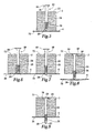
- FIG. 1 is an elevation side view of a self-drilling fastener in accordance with the present invention.
- FIG. 2 is a sectional view of a drilling tip of the self-drilling fastener taken along the line 2 - 2 in FIG. 1.
- FIG. 3 is a top view of a head of the self-drilling fastener.
- FIG. 4 is an enlarged side view of buttress threads of the self-drilling fastener of the present invention.
- FIG. 5 is a side view of a completed wood drilling step.
- FIG. 6 is a side view of a first alternative metal drilling step.
- FIG. 7 is a side view of a second alternative metal drilling step.
- FIG. 8 is a side view of a third alternative metal drilling step.
- FIG. 9 is a side view of a completed clamping step.
- A novel and inventive self-drilling fastener 10 for attaching a
wood substrate 2 to ametal substrate 4 is shown in FIG. 1.Fastener 10 includes anelongate shank 12 having ahead 18 at oneend 14, and awingless drilling tip 20 having adrill point 22 at theopposite end 16. Shank 12 includes anunthreaded portion 24 proximate tohead 18 and a threadedportion 26 betweenunthreaded portion 24 anddrilling tip 20.
Threadedportion 26 axially extends fromdrilling tip 20 towardshead 18, andunthreaded portion 24 axially extends between threadedportion 26 andhead 18.Drilling tip 20 includesdrill point 22 and at least onedrilling flute 28 for directing metal shavings away from a hole drilled byfastener 10. -
Wood substrate 2 could be one of several types of wooden pieces used in construction or fabrication. Examples include wooden support members, plywood and particle board.Metal substrate 4 could be one of many metal supports and is usually made of sheet steel. Examples include corrugated steel roof decks or steel support studs having a thickness between 26 gauge, or about 0.018 inches (about 0,460mm) and 14 gauge, or about 0.075 inches (1,92 mm). Preferably,fastener 10 is used for attaching a wood
substrate 2 that is a wooden support member such as a two-by-four, which currently have a thickness of about 3,84 cm, to a steel support member having a thickness gauge between 24 (about 0,614 mm thick) and 14 (1,92 mm thick). - Turning to FIGS. 1 and 2,
drilling tip 20 is designed to allowfastener 10 to easily drill intometal substrate 4 so thatthreads 30 of threadedportion 26 can drawwood substrate 2 andmetal substrate 4 together.Drilling tip 20 is a conventional wingless drilling tip for drilling into metal; see for exampleU.S. Patent 4,781,506 to Roberts, et al. , the disclosure of which is incorporated herein by reference. As shown in FIG. 2,drilling tip 20 has a generally elliptical cross-section with removedslots 32, which formflutes 28. The elliptical cross-section need not be a true ellipse, but is generally elliptical in form in that it has a major axis L and a minor axis 1, as shown in FIG. 2. In one embodiment, the length of minor axis 1 is about. 0,3 cm, or about 75% of the length of major axis L, which is about 0.38 cm. - Each
slot 32 is framed by a generally planar leadingsurface 34 and a slightly angled trailing surface 36 (see FIG. 1). As shown in FIG. 2, leadingsurface 34 andtrailing surface 36 are separated by an angle θ. Preferably, angle θ is larger than 90 degrees, and is in the range of between about 100 degrees and about 115 degrees. Each leadingsurface 34 includes afirst cutting edge 38 and asecond cutting edge 40. First cuttingedges 38 come together to formdrill point 22, while second cutting edges 40 are located at opposite ends of major axis L, as shown in FIG. 2. Leadingsurfaces 34 ofslots 32 lie generally in the same plane, while trailingsurfaces 36 are slightly skewed, see FIG. 2. Eachflute 28 also includes a generally conically shapedouter surface 42 neardrill point 22 and a generally cylindrically shapedouter surface 44 extending axially betweenconical surface 42 and threadedportion 26, as shown in FIG. 1. - As
fastener 10 is rotated, first cutting edges 38 bite into whichever substrate (eitherwood substrate 2 or metal substrate 4) that is being drilled into. Second cutting edges 40 act to further drill out material whileslots 32 andflutes 28 act to direct material away fromdrilling tip 20 and the hole being drilled. Asdrilling tip 20 cuts away at the substrate,threads 30 eventually engage with the substrate and act to pullfastener 10 through the substrate. - Continuing with FIG. 1, threaded
portion 26 ofshank 12 includes aroot 46 andhelical threads 30 which extend radially fromroot 46. Threadedportion 26 acts to pullfastener 10 throughwood substrate 2 and to drawmetal substrate 4 andwood substrate 2 together in order to clamp the two substrates together. The diameter ofroot 46 is smaller than the outer diameter ofthreads 30. In one embodiment,threads 30 have an outer diameter that is between about 1.3 and about 1.5 times the diameter ofroot 46. In a preferred embodiment,root 46 has a diameter of about 0.15 inches (3.84 mm) andthreads 30 have an outside diameter of about 0.215 inches (5.50 mm). - The thread density of threaded
portion 26 can be between about 13 and about 19 threads per inch (2.56 mm), with a preferred thread density of about 17 threads per inch (2.56 mm). In general, fewer threads per inch (2.56 mm) are needed for thinner metal substrates, and more threads per inch (2.56 mm) are needed for thicker metal substrates. Thread density is described in greater detail in U. S. Patent5,947,670 , the disclosure of which is incorporated herein by reference. - In a preferred embodiment,
threads 30 are buttress threads, as shown in FIG. 4. Eachthread 30 includes a leadingsupport surface 48 on the bottom of eachthread 3 and a trailingsupport surface 50 on the top of eachthread 30. Trailingsupport surface 50 is oriented at a first angle α with respect to a line N normal to the axis ofshank 12. Similarly, leadingsupport surface 48 is inclined at a second angle β with respect to line N, where second angle β of leadingsupport surface 48 is than first angle α of trailingsupport surface 50. In a preferred embodiment, first angle α is about 7 degrees and second angle β is about 30 degrees. Although standard thread forms may be used, the buttress thread configuration shown in FIG. 4 is preferred because it provides higher pullout strengths than standard threads. -
Fastener 10 is designed so that at least one full pitch ofthread 30, and preferably at least two full pitches ofthreads 30, are on either side ofmetal substrate 4 whenfastener 10 is installed (see FIG. 9).. Thelength 52 of threadedportion 26 is greater than thelength 54 ofdrilling tip 20.Length 52 is chosen so that there are fewenough threads 30 so that the threads do not aggressively bite intowood substrate 2 and drawhead 18 through the wood, but so there areenough threads 30 in both the direction towardhead 18 and the direction towarddrilling tip 20. There need to beenough threads 30 towarddrilling tip 20 so there will be enough thread exposed behindsurface 70 of metal substrate 4 (described below) to provide the desired pullout strength forthicker metal substrates 4, such as 1,9 mm thick steel. There also needs to beadequate threads 30 directed towardhead 18 so that there areenough threads 30 incase fastener 10 is overdriven. - In one embodiment,
length 52 of threadedportion 26 is between about 1.5 and about 2.5 times as long aslength 54 ofdrilling tip 20, and preferably about twice as long aslength 54 ofdrilling tip 20. The relationship between the diameter ofroot 46 and the length of major axis L ofdrilling tip 20 depends on the application. For the case of athicker metal substrate 4, such as 14 gauge steel, it is desirable for the length of major axis L to be longer than the diameter ofroot 46 to ensure thatdrilling tip 20 can drill through thethicker metal substrate 4 becauseflutes 28 radially extend farther from the axis ofshank 12 thanroot 46. For athinner metal substrate 4, such as 22 to 24 gauge steel, it may be preferably for the length of major axis L to be shorter than the diameter ofroot 46 so thatflutes 28 do not radially extend as far from the axis asroot 46. -
Unthreaded portion 24 axially extends alongshank 12 from threadedportion 26 to head 18 and includes a flaredportion 66 athead 18. Thelength 56 of unthreadedportion 24 is substantially longer thanlength 52 of threadedportion 26. Flaredportion 66 gradually increases the diameter offastener 10 from unthreadedportion 24 to head 18, as shown in FIG. 1, and has a radius of curvature that is slightly larger than the diameter of unthreadedportion 24. - In one embodiment,
length 56 of unthreadedportion 24 is between about 2.5 to about 3 times longer thanlength 52 of threaded portion, preferablylength 56 of unthreadedportion 24 is between about 2.8 and about 2.9times length 52 of threadedportion 26, and still more preferablylength 56 of unthreadedportion 24 is about 2.85 times longer thanlength 52 of threaded portion. The diameter of unthreadedportion 24 is larger than the diameter ofroot 46, but less than the outer diameter ofthreads 30. In one embodiment, unthreadedportion 24 has a diameter of about 0,45 cm whileroot 46 has a diameter of about 0,38 cm andthreads 30 have an outside diameter of about 0,55 cm. - It is believed that the
extended length 56 of unthreadedportion 24 proximate to head 18 and thesmaller length 52 of threadedportion 26 aid in the attachment ofwood substrate 2 tometal substrate 4. If standard screws having a threaded length that is substantially the entire length of the shank are used for this application, the extended threads tend to engage with the wood substrate and continue to pull the screw through the wood. However, it is believed that the substantiallylonger length 56 of unthreadedportion 24 compared to thesmaller length 52 of threadedportion 26 of the present invention preventfastener 10 from continuing to pull throughwood substrate 2 afterdrill point 22hits metal substrate 4 as described below. Instead, in the present invention there arefewer threads 30 so that threadedportion 26 tends to strip away wood substrate 2 (See FIG. 6) instead of continuing to pull through, allowingfastener 10 to freely rotate inwood substrate 2 so thatthreads 30 andhead 18 can clampwood substrate 2 andmetal substrate 4 together. Oncedrilling tip 20 has drilled throughmetal substrate 4, as described below,threads 30 can tapmetal substrate 4 and draw it towardswood substrate 2 so thatmetal substrate 4 andwood substrate 2 can be tightly clamped together. -
Head 18 provides a clampingsurface 58 which helps clampwood substrate 2 tometal substrate 4, described below.Head 18 also includes drivingsurface 60 having arecess 62 which accepts a bit (not shown) from a fastener driving tool.Head 18 should be of a broad head design, such as a wafer head or a bugle head, because abroad head 18 can preventfastener 10 from pulling throughwood substrate 2. Abugle head 18, as shown in FIG. 1, is preferred because it is believed the bugle head can better stop the forward advancement offastener 10 and preventhead 18 from pulling throughwood substrate 2.Main portion 64 has a relatively short length and has a diameter that is between about 2 and about 3 times greater than the diameter of unthreadedportion 24. -
Recess 62 also can have several configurations, such as a standard Phillips recess, a Phillips Square Drive (PSD) recess to accommodate a bit such as Illinois Tool Works Inc. part number 1588910, or a T-30 6 lobe recess to accommodate a bit such as Illinois Tool Works Inc. part number 18000910. Preferably,recess 62 is a PSD recess, as shown in FIG. 3, or a T-30 6 lobe recess (not shown) because they allow for better stability asfastener 10 is being driven and prevent cam-out of the bit. - As stated above, a preferred application for
fastener 10 is the attachment of wooden support members having a thickness of about 3,84 cm, such as two-by-fours, to steel support members between 24 and 14 gauge, and preferably to steel support members between 18 and 22 gauge. For this application,fastener 10 has a total length of between about 4,5 cm and about 5,8 cm, and preferablyfastener 10 has a total length of about 5,1 cm.Drilling tip 20 has a length of between about 0,55 cm and about 0.58 cm, with a preferred length ofdrilling tip 20 of about 0.56 cm. Threadedportion 26 has a length of between about 0,9 cm and about 1,28 cm, and preferably threaded portion has a length of about 1,05 cm. It also is preferred thatend 68 of threadedportion 26 proximate todrilling tip 20 be at least about 4,42 cm away from drivingsurface 60 ofhead 18 to ensure that one or more pitches ofthreads 30, and preferably at least two pitches ofthread 30 are on each side ofmetal substrate 4 whenfastener 10 is installed, as described above.Unthreaded portion 24, including flaredportion 66, has a length between about 3,2 cm and about 3,84 cm, with a preferred length of unthreaded portion being about 3,33 cm to about 3,50 cm, and a still more preferred length of unthreaded portion being about 3,35 cm.Main portion 64 ofhead 18 has a length of between about 0,51 mm to about 1,28 mm, with a preferred length ofmain portion 64 being about 0,77 mm. In the preferred embodiment, the diameter ofdrilling tip 20 androot 46 is about 0,38 cm, the outer diameter ofthreads 30 is about 0,55 cm, the diameter of unthreadedportion 24 is about 0,43 cm and the diameter ofmain portion 64 ofhead 18 is about 1,20 cm. Of course, it is contemplated that the above listed dimensions may vary depending on the particular application and substrate conditions. - An advantage of the preferred embodiment over the prior screws described above are that
fastener 10 of the present invention can be made from less material than the prior screws because it is shorter than many screws used for the application of attaching wood with a 3,84 cm thickness to a medium to light gauge steel, where screws have been as long as 5,8 cm to 9 cm or more. Theshorter fastener 10 is less expensive than the longer, prior screws. Further, becausefastener 10 is shorter it provides for a shorter drill time, allowing a plurality offasteners 10 of the present invention to be quickly installed. Another advantage offastener 10 of the present invention is that because it is shorter, it is easier to handle and easier to keep stable as it is being driven, as shorter fasteners tend to be less wobbly and easier to handle than longer fasteners. - The method by which
fastener 10 attacheswood substrate 2 tometal substrate 4 includes the steps of placingwood substrate 2 againstmetal substrate 4 in a desired position, selecting afastener 10 for fastening the substrates,positioning drilling tip 20 offastener 10 at a selected position onwood substrate 2, fitting a bit of a fastener driving tool (not shown) intorecess 62, rotatingfastener 10 with the fastener driving tool so that cuttingsurfaces wood substrate 2 until threadedportion 26 engages inwood substrate 2 and pullsfastener 10 throughwood substrate 2.Threads 30 of threadedportion 26pull fastener 10 throughwood substrate 2 untildrill point 22 comes into contact withmetal substrate 4, when cutting surfaces 38 and 40 engage and drill intometal substrate 4 untilthreads 30tap metal substrate 4 and pullwood substrate 2 andmetal substrate 4 together so thatmetal substrate 4 is clamped tight againstwood substrate 2. The method can then be repeated with anotherfastener 10, either by drilling into thesame wood substrate 2 to provide stability by attachment at a different location, where thenew fastener 10 could attachwood substrate 2 to thesame metal substrate 4 or to a second metal substrate (not shown), or thenew fastener 10 can be driven into a second wood substrate (not shown) to attach the second wood substrate to thesame metal substrate 4 or to a second metal substrate. -
Fastener 10 has the advantage of not requiring a separate wood drilling step because drillingtip 20 easily drills throughwood substrate 2. Some fasteners have required thatwood substrate 2 be pre-drilled, and that the fastener is used to only drill throughmetal substrate 4. The pre-drilling step for these fasteners helps to avoid problems such as "wood jacking" where the threads engage the wood and force it, or "jack" it, away from the metal. A separate pre-drilling step such as one described requires more time per fastener, so that an installer cannot install the fasteners as fast as he or she could with a plurality offasteners 10. The wood drilling step of the present invention, described above, allowsdrilling tip 20 offastener 10 to drill throughwood substrate 2 untildrill point 22hits metal substrate 4 withoutthreads 30 causing "wood jacking" ofwood substrate 2. After drill point hitsmetal substrate 4,drilling tip 20 drills throughmetal substrate 4 without having to change between a drill bit and a fastener intended solely for metal drilling. - Preferably,
fastener 10 is rotated by a fastener driving tool (not shown) which provides the driving energy necessary to rotatefastener 10. Asfastener 10 rotates,drilling tip 20 drills intowood substrate 2 andthreads 30pull fastener 10 forward throughwood substrate 2 untildrill point 22hits metal substrate 4. - After
drill point 22hits metal substrate 4,fastener 10 goes through one of at least three alternative metal drilling steps. The first alternative metal drilling step occurs when pressure is applied towood substrate 2 to force it down ontometal substrate 4 and prevent the substrates from pushing apart. One method of applying this pressure is by stepping down onwood substrate 2 while drivingfastener 10. The first alternative metal drilling step also occurs when eitherwood substrate 2 is a softer wood, or whenmetal substrate 4 has a heavy gauge, or both. In this alternative,drill point 22hits metal substrate 4 but does not easily pierce it, causingthreads 30 offastener 10 to spin inwood substrate 2 and strip away wood aroundthreads 30, as shown in FIG. 6. Asfastener 10 spins,drilling tip 20 drills into and throughmetal substrate 4. - A second alternative metal drilling step occurs when pressure is applied to
wood substrate 2 and whenwood substrate 2 is a harder wood, or whenmetal substrate 4 has a lighter gauge, or both. In this alternative, whendrill point 22hits metal substrate 4 it causesthreads 30 to engage inwood substrate 2. The engagedthreads 30 provide a force betweendrill point 22 andmetal substrate 4, causingdrill point 22 to pierce throughmetal substrate 4, as shown in FIG. 7, allowingdrilling tip 20 to drill throughmetal substrate 4. - A third alternative metal drilling step is shown in FIG. 8. In this alternative, no pressure is applied to
wood substrate 2 to force it againstmetal substrate 4. In this case, asfastener 10 is driventhreads 30 continue to drivefastener 10 forward and drillpoint 22 pusheswood substrate 2 andmetal substrate 4 apart. Eventually,metal substrate 4 andwood substrate 2 cannot be pushed apart any farther, andthreads 30 begin to strip away some of the wood inwood substrate 2, as shown in FIG. 8, allowingfastener 10 to freely rotate so thatdrill point 22 drills throughmetal substrate 4 untilthreads 30tap metal substrate 4. - After
fastener 10 has drilled throughmetal substrate 4,fastener 10 is driven forward untilthreads 30tap metal substrate 4 to allowwood substrate 2 and metal substrate 4-to be drawn towards each other so that the substrates can be clamped together. The final step in attachingwood substrate 2 tometal substrate 4 withfastener 10 is a clamping step. In the clamping step,fastener 10 is rotated and trailingsupport surface 50 ofthreads 30 acts against abottom surface 70 ofmetal substrate 4 to drawwood substrate 2 towardsmetal substrate 4. Eventually, clampingsurface 58 ofbroad head 18 comes into contact withtop surface 72 ofwood substrate 2 and preventsfastener 10 from pulling throughwood substrate 2 so that as trailingsupport surface 30 engagesmetal substrate 4,wood substrate 2 andmetal substrate 4 are clamped together. - Surprisingly it has been found that the
shorter length 52 of threadedportion 26 and the substantiallylonger length 56 of unthreadedportion 24 allowsfastener 10 to drawmetal substrate 4 andwood substrate 2 together no matter which of the three alternative metal drilling steps occurs. This is believed to occur because there arefewer threads 30 to engagewood substrate 2, which preventsfastener 10 from continuing to pull throughwood substrate 2, but instead allowsthread 30 to drawwood substrate 2 towardsmetal substrate 4 and clamp them together. - In the present invention, after threaded
portion 26 has pulledfastener 10 through wood substrate, a substantial portion ofshank 12 that is still inwood substrate 2 is unthreadedportion 24, which tends to spin inwood substrate 2 without continuing to drivefastener 10 forward. It is also believed that the remainingthreads 30 inwood substrate 2 do not provide enough force to drivefastener 10 forward so thatfastener 10 spins without continuing to be driven. Therefore,threads 30 are allowed to tapmetal substrate 4 and clamp it againstwood substrate 2, as shown in FIG. 9. Asfastener 10 rotates withinwood substrate 2, trailingsupport surface 50 ofthreads 30 engagemetal substrate 4 and draw it towardswood substrate 2. - The present invention provides a novel fastener for clamping attachment of a two-by-four to a light gauge metal substrate where the unthreaded portion proximate the head is substantially longer than a threaded portion. The threaded portion needs to have few enough threads so that the fastener is self-tapping and so that the threads strip out the wood, if necessary, after traveling through the wood so that the fastener will clamp the wood and metal together instead of continuing to drive through the wood.
Claims (11)
- A self-drilling fastener (10) for attaching wood substrates (2) to metal substrates (4) comprising:an elongate shank (12) defining an axis and having a first end (16) and a second end (14);a drilling tip (20) at the first end (16) of the shank, the drilling tip having a drill point (22) and an axial length;a broad head (18) formed at the second end (14) of the shank;wherein the shank has a threaded portion (26) axially extending from the drilling tip (20) towards the head, the threaded portion having helical threads (30), an axial length of between about 0,9 cm and about 1,28 cm, a root diameter and a thread diameter, the thread diameter being greater than the root diameter, the length of the threaded portion (26) being greater than the length of the drilling tip (20); and
wherein the shank has an unthreaded portion (24) axially extending from the threaded portion (26) to the head (18), the unthreaded portion having an axial length and a diameter, the diameter of the unthreaded portion being smaller than the thread diameter, the length of the unthreaded portion being substantially greater than the length of the threaded portion. - A self-drilling fastener according to claim 1, wherein the fastener has a total length of about 5,12 cm.
- A self-drilling fastener according to claim 1, wherein the length of the threaded portion (26) is between about 1.5 and about 2.5 times the length of the drilling tip (20), and the length of the unthreaded portion (24) is between about 2.5 and about 3 times the length of the threaded portion (26).
- A self-drilling fastener according to claim 1, wherein the length of the drilling tip (20) is about 0.512 cm, the length of the threaded portion (26) is about 1,02 cm and the length of the unthreaded portion (24) is about 3 cm.
- A self-drilling fastener according to claim 1, wherein the drilling tip (20) further comprises at least one flute (28).
- A self-drilling fastener according to claim 1, wherein the broad head (18) is a bugle head.
- A self-drilling fastener according to claim 1, wherein the broad head (18) is a wafer head.
- A self-drilling fastener according to claim 1, wherein the threads (30) are buttress threads.
- A self-drilling fastener according to claim 8, wherein the buttress threads (30) include a leading support surface (48) and a trailing support surface (50), wherein the trailing support surface is oriented at a first predetermined angle (α) with respect to a line normal to the axis of the shank, and the leading support surface is inclined with respect to the normal line at a second predetermined angle (β)which is greater than the first predetermined.
- A self-drilling fastener according to claim 9, wherein the first angle (α) is about 7 degrees with respect to the normal line and the second angle (β) is about 30 degrees with respect to the normal line.
- A self-drilling fastener according to claim 1, wherein the drilling tip (20) has a major axis, the major axis having a length, wherein the length of the major axis is greater than the root diameter of the threaded portion.
Applications Claiming Priority (2)
| Application Number | Priority Date | Filing Date | Title |
|---|---|---|---|
| US171000 | 2002-06-13 | ||
| US10/171,000 US6923611B2 (en) | 2002-06-13 | 2002-06-13 | Self-drilling fastener |
Publications (2)
| Publication Number | Publication Date |
|---|---|
| EP1371862A1 EP1371862A1 (en) | 2003-12-17 |
| EP1371862B1 true EP1371862B1 (en) | 2007-12-05 |
Family
ID=29583850
Family Applications (1)
| Application Number | Title | Priority Date | Filing Date |
|---|---|---|---|
| EP03291411A Expired - Lifetime EP1371862B1 (en) | 2002-06-13 | 2003-06-13 | Self-drilling fastener |
Country Status (6)
| Country | Link |
|---|---|
| US (1) | US6923611B2 (en) |
| EP (1) | EP1371862B1 (en) |
| JP (1) | JP2004019946A (en) |
| AU (1) | AU2003204604B2 (en) |
| CA (1) | CA2432093C (en) |
| DE (1) | DE60317851T2 (en) |
Cited By (1)
| Publication number | Priority date | Publication date | Assignee | Title |
|---|---|---|---|---|
| RU2702674C2 (en) * | 2015-02-16 | 2019-10-09 | Кинги Ой | Mounting screw |
Families Citing this family (35)
| Publication number | Priority date | Publication date | Assignee | Title |
|---|---|---|---|---|
| US6854237B2 (en) * | 1999-04-16 | 2005-02-15 | Steeler Inc. | Structural walls |
| US20040156696A1 (en) * | 2002-11-27 | 2004-08-12 | Grosch Gregory E. | Fastener for fiberglass and other composite structures |
| US7207248B2 (en) * | 2003-10-09 | 2007-04-24 | Illinois Tool Works Inc. | Threaded screw fastener characterized by high pull-out resistance, reduced installation torque, and unique head structure and drive socket implement or tool therefor |
| JP2006057729A (en) * | 2004-08-20 | 2006-03-02 | Taisei Corp | Lumber joining screw member and lumber joining structure using it |
| US20070166126A1 (en) * | 2006-01-13 | 2007-07-19 | Donald Harney | Apparatus for securing siding |
| DE102006026176A1 (en) * | 2006-05-29 | 2007-12-06 | Adolf Würth GmbH & Co. KG | Self-drilling screw |
| JP2007327540A (en) * | 2006-06-07 | 2007-12-20 | Higashi Nippon Power Fastening Kk | Rafter fixing wood screw |
| DE102006057259A1 (en) * | 2006-11-22 | 2008-05-29 | Swg Schraubenwerk Gaisbach Gmbh | screw |
| US8449234B2 (en) * | 2007-01-16 | 2013-05-28 | Harry E. Taylor | Blind rivet |
| US7682118B2 (en) * | 2007-04-19 | 2010-03-23 | Illinois Tool Works Inc. | Threaded screw fastener with multiple characteristic threads |
| DE102007024224A1 (en) * | 2007-05-11 | 2008-11-20 | Adolf Würth GmbH & Co. KG | Self-drilling screw |
| US7900783B2 (en) | 2007-12-04 | 2011-03-08 | Clairson, Inc. | Standard and track shelving systems |
| US8646624B2 (en) | 2007-12-04 | 2014-02-11 | Clairson, Inc. | Standard and track shelving systems |
| US20100098482A1 (en) * | 2008-10-20 | 2010-04-22 | Belinda Richard L | Compression pin fastener |
| CA2647663C (en) * | 2008-12-19 | 2013-08-20 | Mirco Walther | Self-counter-sinking screw with circumferential cutters |
| AU2010200204B2 (en) * | 2009-01-21 | 2015-07-02 | Illinois Tool Works Inc. | Self drilling screw |
| CN102272466B (en) | 2009-02-12 | 2014-09-03 | 艺术螺丝钉有限会社 | Fastener and fastening structure |
| US8132768B2 (en) | 2009-07-22 | 2012-03-13 | Clairson, Inc. | Shelving end brackets with interchangeable pieces for supporting hang rods of different sizes |
| USD631734S1 (en) | 2009-07-22 | 2011-02-01 | Clairson, Inc. | End bracket |
| US20120183371A1 (en) * | 2009-10-05 | 2012-07-19 | Druschel Thomas P | Engineered Lumber Panel Fastener |
| ITPV20100003A1 (en) * | 2010-03-11 | 2011-09-12 | Carlo Vittorio Sala | ANTIBIDDING THREAD AND RELATED THREAD TOOL, FOR THERMOPLASTIC MATERIALS, COMMON THERMO-HARDENERS AND LOADED WITH INERT MATERIALS, CARBON AND GLASS FIBERS, WOOD AND ITS COMPOUNDS, CONCRETE, PLASTER, INSULATING MATERIALS, WITH R |
| US8434629B2 (en) | 2011-04-08 | 2013-05-07 | Clairson Inc. | Adjustable shelving system with overlapping tracks |
| USD668945S1 (en) | 2011-04-08 | 2012-10-16 | Clairson, Inc. | Track for a shelving system |
| US9482258B2 (en) | 2012-05-10 | 2016-11-01 | Simpson Strong-Tie Company, Inc. | Fastener with multiple threaded regions |
| WO2014018542A1 (en) * | 2012-07-23 | 2014-01-30 | Simpson Strong-Tie Company, Inc. | Fastener with drill pilot and reversed threaded regions |
| US10197086B2 (en) * | 2015-07-31 | 2019-02-05 | Infastech Intellectual Properties Pte. Ltd | Threaded fastener |
| US11326638B2 (en) | 2016-10-07 | 2022-05-10 | Illinois Tool Works Inc. | Threaded fastener with a hybrid self-drilling tip |
| USD908476S1 (en) * | 2016-12-20 | 2021-01-26 | Avvio Gmbh & Co Kg | Screw |
| MX2020002569A (en) | 2017-09-06 | 2020-09-03 | Armstrong World Ind Inc | Multi-featured panel fastener and panel system including the multi-featured panel fastener. |
| US11253060B2 (en) | 2018-10-31 | 2022-02-22 | American Woodmark Corporation | Modular enclosure system |
| US11598362B2 (en) * | 2019-09-19 | 2023-03-07 | Ideal Fasterners Pty Ltd. | Screw fasteners for use in building construction |
| US12000421B2 (en) | 2021-01-07 | 2024-06-04 | Illinois Tool Works Inc. | Self-drilling self-tapping fastener |
| CN113134799A (en) * | 2021-03-22 | 2021-07-20 | 郑州工业应用技术学院 | Multifunctional wrench for automobile maintenance |
| US11808042B2 (en) | 2021-05-21 | 2023-11-07 | Unirac Inc. | Attachment bracket apparatus |
| USD988853S1 (en) | 2021-05-21 | 2023-06-13 | Unirac Inc. | Bracket |
Family Cites Families (23)
| Publication number | Priority date | Publication date | Assignee | Title |
|---|---|---|---|---|
| US3524378A (en) | 1968-12-05 | 1970-08-18 | Illinois Tool Works | Stitching screw |
| US3529697A (en) * | 1969-05-26 | 1970-09-22 | Ernest F Kossian | Collapsible saw horse |
| DE2555322A1 (en) | 1975-12-09 | 1977-06-23 | Geb Graebner Renate Haubold | Wood screw with smooth upper shank - has threads stripped for clearance fit through first panel |
| US4125051A (en) | 1977-06-09 | 1978-11-14 | Illinois Tool Works Inc. | Tamperproof fastener |
| US4361997A (en) * | 1980-02-25 | 1982-12-07 | Textron Inc. | Fastener plate and assembly |
| US4453361A (en) * | 1982-04-19 | 1984-06-12 | Construction Fasteners, Inc. | Screw fastener assembly, method of providing same, and fastener suitable for use therein |
| US4780039A (en) * | 1983-09-19 | 1988-10-25 | The B. F. Goodrich Company | Fastener plate |
| EP0302909B1 (en) * | 1987-01-21 | 1991-06-19 | SFS Stadler Holding AG | Fastening element with large-area plain washer |
| FR2676244B1 (en) * | 1991-05-07 | 1994-01-28 | Francis Ovaert | COMPOSITE STRUCTURE, ESPECIALLY FOR THE BUILDING. |
| CA2099228C (en) | 1992-06-26 | 1996-05-21 | Emanuel Sam Fardell | Fastening nail |
| US5540531A (en) * | 1993-02-24 | 1996-07-30 | Olympic Manufacturing Group, Inc. | Panel fastener |
| JP2809584B2 (en) * | 1993-12-13 | 1998-10-08 | 光洋器材株式会社 | Insert for deck plate |
| US5489179A (en) | 1994-08-19 | 1996-02-06 | Illinois Tool Works Inc. | Fastener and building assembly comprising workpiece, substrate, and fastener |
| US5741104A (en) | 1994-08-19 | 1998-04-21 | Illinois Tool Works Inc. | Steel fastener having grooved shank |
| DE69505212T2 (en) | 1994-08-19 | 1999-03-04 | Illinois Tool Works Inc., Glenview, Ill. | Fastening element with polymer-coated shaft |
| DE4445806C1 (en) | 1994-12-21 | 1996-08-29 | Sfs Ind Holding Ag | Hole-forming and thread-forming screw and method for screwing them in |
| DE19615191C5 (en) | 1996-04-17 | 2006-02-09 | Sfs Intec Holding Ag | Screw and method for torque limited mounting of metal and / or plastic profiles or plates on a substructure |
| US5605423A (en) * | 1996-04-26 | 1997-02-25 | Elco Textron, In. | Self-drilling stud |
| CA2184217C (en) | 1996-06-26 | 1999-04-13 | Daniel Onofrio | Plywood fastener |
| US5947670A (en) * | 1996-09-20 | 1999-09-07 | Illinois Tool Works Inc. | Self-drilling fastener |
| AUPO502997A0 (en) | 1997-02-11 | 1997-03-06 | W.A. Deutscher Pty Ltd | Fastening screw and fastening system |
| US5810534A (en) | 1997-02-14 | 1998-09-22 | Senco Products, Inc. | Cleated nail having enlarged diameter shank portion |
| US5816012A (en) | 1997-03-10 | 1998-10-06 | Alpine Engineered Products, Inc. | Dual threaded fastener and metal component assembly |
-
2002
- 2002-06-13 US US10/171,000 patent/US6923611B2/en not_active Expired - Fee Related
-
2003
- 2003-05-30 JP JP2003154364A patent/JP2004019946A/en active Pending
- 2003-06-10 AU AU2003204604A patent/AU2003204604B2/en not_active Ceased
- 2003-06-12 CA CA002432093A patent/CA2432093C/en not_active Expired - Fee Related
- 2003-06-13 EP EP03291411A patent/EP1371862B1/en not_active Expired - Lifetime
- 2003-06-13 DE DE60317851T patent/DE60317851T2/en not_active Expired - Lifetime
Cited By (1)
| Publication number | Priority date | Publication date | Assignee | Title |
|---|---|---|---|---|
| RU2702674C2 (en) * | 2015-02-16 | 2019-10-09 | Кинги Ой | Mounting screw |
Also Published As
| Publication number | Publication date |
|---|---|
| DE60317851D1 (en) | 2008-01-17 |
| JP2004019946A (en) | 2004-01-22 |
| US6923611B2 (en) | 2005-08-02 |
| US20030231941A1 (en) | 2003-12-18 |
| EP1371862A1 (en) | 2003-12-17 |
| DE60317851T2 (en) | 2008-12-11 |
| CA2432093A1 (en) | 2003-12-13 |
| AU2003204604B2 (en) | 2004-11-04 |
| AU2003204604A1 (en) | 2004-01-15 |
| CA2432093C (en) | 2007-08-21 |
Similar Documents
| Publication | Publication Date | Title |
|---|---|---|
| EP1371862B1 (en) | Self-drilling fastener | |
| US8192123B2 (en) | Drywall fastener | |
| US5039262A (en) | Self-drilling wall anchor | |
| US5482418A (en) | Self-drilling anchor | |
| US5516248A (en) | Low torque wood screw | |
| US6676353B1 (en) | Self-drilling, self-tapping screws | |
| US5692864A (en) | Self-threading anchor with spreadable leg portions joined by a frangible drill end portion | |
| US6186716B1 (en) | Anchor bolt | |
| CA2465394C (en) | Knurled fastener with cutting edges and removable head | |
| US20060018730A1 (en) | Drywall fastener | |
| US3977142A (en) | Floor nail | |
| US20080124187A1 (en) | Self-drilling, self-tapping screw fasteners | |
| US5865584A (en) | Plywood fastener for affixing plywood to light gauge sheet metal | |
| AU2010200204B2 (en) | Self drilling screw | |
| GB2454464A (en) | Screw having an oval shank | |
| EP3677800A1 (en) | Wood screw | |
| AU669986B2 (en) | Improved self-drilling wall anchor | |
| EP3995708A1 (en) | Drywall screw | |
| AU2007293015B2 (en) | Drywall fastener | |
| GB2428761A (en) | Screw |
Legal Events
| Date | Code | Title | Description |
|---|---|---|---|
| PUAI | Public reference made under article 153(3) epc to a published international application that has entered the european phase |
Free format text: ORIGINAL CODE: 0009012 |
|
| AK | Designated contracting states |
Kind code of ref document: A1 Designated state(s): AT BE BG CH CY CZ DE DK EE ES FI FR GB GR HU IE IT LI LU MC NL PT RO SE SI SK TR |
|
| AX | Request for extension of the european patent |
Extension state: AL LT LV MK |
|
| 17P | Request for examination filed |
Effective date: 20040525 |
|
| 17Q | First examination report despatched |
Effective date: 20040708 |
|
| AKX | Designation fees paid |
Designated state(s): DE FR GB |
|
| 17Q | First examination report despatched |
Effective date: 20040708 |
|
| GRAP | Despatch of communication of intention to grant a patent |
Free format text: ORIGINAL CODE: EPIDOSNIGR1 |
|
| GRAS | Grant fee paid |
Free format text: ORIGINAL CODE: EPIDOSNIGR3 |
|
| GRAA | (expected) grant |
Free format text: ORIGINAL CODE: 0009210 |
|
| AK | Designated contracting states |
Kind code of ref document: B1 Designated state(s): DE FR GB |
|
| REG | Reference to a national code |
Ref country code: GB Ref legal event code: FG4D |
|
| REF | Corresponds to: |
Ref document number: 60317851 Country of ref document: DE Date of ref document: 20080117 Kind code of ref document: P |
|
| ET | Fr: translation filed | ||
| PLBE | No opposition filed within time limit |
Free format text: ORIGINAL CODE: 0009261 |
|
| STAA | Information on the status of an ep patent application or granted ep patent |
Free format text: STATUS: NO OPPOSITION FILED WITHIN TIME LIMIT |
|
| 26N | No opposition filed |
Effective date: 20080908 |
|
| PGFP | Annual fee paid to national office [announced via postgrant information from national office to epo] |
Ref country code: DE Payment date: 20130627 Year of fee payment: 11 Ref country code: GB Payment date: 20130627 Year of fee payment: 11 |
|
| PGFP | Annual fee paid to national office [announced via postgrant information from national office to epo] |
Ref country code: FR Payment date: 20130702 Year of fee payment: 11 |
|
| REG | Reference to a national code |
Ref country code: DE Ref legal event code: R119 Ref document number: 60317851 Country of ref document: DE |
|
| GBPC | Gb: european patent ceased through non-payment of renewal fee |
Effective date: 20140613 |
|
| REG | Reference to a national code |
Ref country code: DE Ref legal event code: R119 Ref document number: 60317851 Country of ref document: DE Effective date: 20150101 |
|
| REG | Reference to a national code |
Ref country code: FR Ref legal event code: ST Effective date: 20150227 |
|
| PG25 | Lapsed in a contracting state [announced via postgrant information from national office to epo] |
Ref country code: DE Free format text: LAPSE BECAUSE OF NON-PAYMENT OF DUE FEES Effective date: 20150101 |
|
| PG25 | Lapsed in a contracting state [announced via postgrant information from national office to epo] |
Ref country code: GB Free format text: LAPSE BECAUSE OF NON-PAYMENT OF DUE FEES Effective date: 20140613 Ref country code: FR Free format text: LAPSE BECAUSE OF NON-PAYMENT OF DUE FEES Effective date: 20140630 |