EP1371443B1 - A system and method for monitoring laser welds and giving an indication of the quality of welding - Google Patents
A system and method for monitoring laser welds and giving an indication of the quality of welding Download PDFInfo
- Publication number
- EP1371443B1 EP1371443B1 EP03009130A EP03009130A EP1371443B1 EP 1371443 B1 EP1371443 B1 EP 1371443B1 EP 03009130 A EP03009130 A EP 03009130A EP 03009130 A EP03009130 A EP 03009130A EP 1371443 B1 EP1371443 B1 EP 1371443B1
- Authority
- EP
- European Patent Office
- Prior art keywords
- signal
- power
- extracting
- laser beam
- classifying
- Prior art date
- Legal status (The legal status is an assumption and is not a legal conclusion. Google has not performed a legal analysis and makes no representation as to the accuracy of the status listed.)
- Expired - Lifetime
Links
Images


Classifications
-
- B—PERFORMING OPERATIONS; TRANSPORTING
- B23—MACHINE TOOLS; METAL-WORKING NOT OTHERWISE PROVIDED FOR
- B23K—SOLDERING OR UNSOLDERING; WELDING; CLADDING OR PLATING BY SOLDERING OR WELDING; CUTTING BY APPLYING HEAT LOCALLY, e.g. FLAME CUTTING; WORKING BY LASER BEAM
- B23K26/00—Working by laser beam, e.g. welding, cutting or boring
- B23K26/02—Positioning or observing the workpiece, e.g. with respect to the point of impact; Aligning, aiming or focusing the laser beam
- B23K26/03—Observing, e.g. monitoring, the workpiece
- B23K26/032—Observing, e.g. monitoring, the workpiece using optical means
-
- B—PERFORMING OPERATIONS; TRANSPORTING
- B23—MACHINE TOOLS; METAL-WORKING NOT OTHERWISE PROVIDED FOR
- B23K—SOLDERING OR UNSOLDERING; WELDING; CLADDING OR PLATING BY SOLDERING OR WELDING; CUTTING BY APPLYING HEAT LOCALLY, e.g. FLAME CUTTING; WORKING BY LASER BEAM
- B23K26/00—Working by laser beam, e.g. welding, cutting or boring
- B23K26/20—Bonding
- B23K26/21—Bonding by welding
-
- B—PERFORMING OPERATIONS; TRANSPORTING
- B23—MACHINE TOOLS; METAL-WORKING NOT OTHERWISE PROVIDED FOR
- B23K—SOLDERING OR UNSOLDERING; WELDING; CLADDING OR PLATING BY SOLDERING OR WELDING; CUTTING BY APPLYING HEAT LOCALLY, e.g. FLAME CUTTING; WORKING BY LASER BEAM
- B23K31/00—Processes relevant to this subclass, specially adapted for particular articles or purposes, but not covered by any single one of main groups B23K1/00 - B23K28/00
- B23K31/12—Processes relevant to this subclass, specially adapted for particular articles or purposes, but not covered by any single one of main groups B23K1/00 - B23K28/00 relating to investigating the properties, e.g. the weldability, of materials
- B23K31/125—Weld quality monitoring
-
- G—PHYSICS
- G01—MEASURING; TESTING
- G01N—INVESTIGATING OR ANALYSING MATERIALS BY DETERMINING THEIR CHEMICAL OR PHYSICAL PROPERTIES
- G01N21/00—Investigating or analysing materials by the use of optical means, i.e. using sub-millimetre waves, infrared, visible or ultraviolet light
- G01N21/62—Systems in which the material investigated is excited whereby it emits light or causes a change in wavelength of the incident light
- G01N21/71—Systems in which the material investigated is excited whereby it emits light or causes a change in wavelength of the incident light thermally excited
- G01N21/718—Laser microanalysis, i.e. with formation of sample plasma
-
- G—PHYSICS
- G01—MEASURING; TESTING
- G01N—INVESTIGATING OR ANALYSING MATERIALS BY DETERMINING THEIR CHEMICAL OR PHYSICAL PROPERTIES
- G01N25/00—Investigating or analyzing materials by the use of thermal means
- G01N25/72—Investigating presence of flaws
Definitions
- the subject of the present invention is a system and a method for monitoring laser welds according to the preambles of, respectively, claims 1 and 13 (see, for example, the article "Aspects of quality assurance with plasma monitoring system during laser beam welding" by K. ZIMMERMANN et al, in LASER IN DER TECHNIK, 1994, pp 503-510).
- Said inspection step constitutes an activity which involves considerable waste of time and which rarely provides the operator with useful indications on how the process itself may be perfected, for example by refining some of its parameters.
- external visual inspection of the welded products entails a costly procedure, which is more often than not carried out using ultrasound devices.
- a different approach consists in providing for an on-line analysis of quality performed directly during the process. The systems of this type so far produced are, however, able to identify only some of the possible welding defects, and moreover in a way that is rather unsatisfactory, as well as being somewhat insensitive to the different set-ups of the laser device.
- a further drawback of currently available systems lies in the fact that they are based upon reference signals indicating an optimal process or, in some cases, a process presenting defects, and compare the signal associated to the actual process with the aforesaid specially constructed reference signals.
- the major problem of such systems is that they involve the use of a number of reference signals which ranges from a minimum of two to more than ten.
- the preparation of such reference signals poses various problems. In the first place, preparing a certain number of repeatable references entails the presence of a skilled operator who is able to certify the goodness of the process. In addition, for certain applications, the creation of even just two references leads to a waste of material. Finally, there is the difficulty of obtaining references associated to a process that presents defects.
- the phenomenon of welding may be defined as the localized coalescence of metals or non-metals produced by heat and/or pressure.
- a laser beam can be focused in very small areas. The concentration of power enables the welding process to be achieved. Since a laser beam is a beam made up of light radiation, the reflecting properties of the metals determine which part of the beam is to be reflected, so that even a large part of the incident power can bounce back. This problem is increased by the fact that the majority of industrial lasers emit infrared light, which is reflected by metals even better than is visible light. This situation changes drastically when the surface of the structure subjected to welding starts to melt.
- the liquid metals absorb much more power from the incident radiation as compared to solid metals, so that the flow of heat absorbed increases suddenly, thus raising the temperature of the metal above the boiling point and generating metal vapour.
- the pressure of this vapour opens a narrow and deep channel around the laser beam, so forming a melted area having a keyhole-like profile (the so-called "keyhole”).
- the ratio between the depth and width of the laser-welding areas shaped like a keyhole may reach values of up to 10:1 but is more commonly in the region of 4:1.
- Keyhole welding is a threshold process: when the incident radiation is low, little power is absorbed; once the radiation becomes high enough to form a keyhole, the majority of the power is absorbed by the welded component. Small variations of power in the proximity of the threshold of the keyhole cause very considerable changes in the quality of the weld.
- Laser devices have the appreciable property of producing thin and deep welds, so that it is common to adopt a butt-welding configuration. Said configuration makes possible a high welding speed and requires a low supply of heat since all the metal of the weld is used in the joint. Also irrespective of said configuration, in laser welding the correct coupling of the elements to be welded in the area of the joint is critical. Almost all laser welds are autogenous; i.e., no weld material is used. Any space left in the area of the joint can become a void in the welded product obtained.
- a focused laser beam can pass through a butt joint in which a space of 0.2 mm has been left without causing any welding.
- the beam simply bounces off the facing walls of the elements to be welded and exits on the opposite side.
- the material to be welded must be clean. Any non-metallic contaminant is ejected from the keyhole, producing splashes, porosities and the risk of damage to the focusing optical devices.
- the process according to the invention is aimed at detecting in particular the following defects of the laser weld:
- the purpose of the present invention is to provide a monitoring system and method which will be able to recognize accurately all the aforesaid defects through a process which can be carried out also on line and in real time.
- the subject of the invention is a system and a method for monitoring laser welds as defined in claims 1 and 13 respectively.
- the reference number 1 designates the head of a focusing laser (illustrated only schematically), which focuses a laser beam 2 on a structure to be welded 3, for example by means of two successive reflections from a half-silvered mirror 4 and a conventional mirror 5.
- the half-silvered mirror 4 is a zinc-selenium mirror with an absorption of 0.2%.
- the radiation reflected by the structure 3 undergoing welding is again reflected by the mirror 5 towards the half-silvered mirror 4, passes through the latter and is focused by a filtering lens 7 on a photodiode sensor 8.
- the signal at output from the sensor 8 is sent to an electronic processing unit 9, which displays at one output 10 the quality of the weld.
- the processing unit 9 can comprise, for example, a data-acquisition card, of the NI 6110E PC card type, with an acquisition frequency of 5 Msamples per sec, as well as a plurality of personal computers, for example of the 800-MHz Pentium III type. Analysis of the quality of the weld obtained using the system according to the invention is based not only upon the signal at output from the photodiode 8, which is linked to the radiation produced by the welding process and comes from the structure to be welded, but also upon the signal indicating the grid current of the laser, which is linked to the power of the laser and which also comes from the component welded.
- the grid-current signal is used for identifying reductions in the level of power of the laser source and drops in power of the laser source.
- the signal coming from the photodiode is used for identifying possible defects, such as insufficient depth of penetration, misalignments in the coupling of the pieces, or porosities.
- the first step of the procedure of processing downstream of sampling of the signals is a lowpass pre-filtering step, necessary for reducing the high-frequency noise typically present in the industrial context.
- the appropriate filtering frequency is established by means of a spectral analysis, which identifies the higher-frequency components of the signals.
- an operation of down-sampling is carried out in order to reduce the cardinality of the set of data, with the intent of speeding up the operation of extraction of the characteristics of the signals and the subsequent classification.
- the ratio of down-sampling is identified downstream, after prior definition of a maximum tolerable limit for the execution of the procedure.
- the step of extraction of the characteristics from the signals is based upon generation of a function that interpolates the signal and subsequent extraction of appropriate indices of deviation. Examples of index of deviation extracted from the signals involved in the process in question are:
- the final step of the algorithm entails the construction of a classifier, which, by receiving at input the characteristics identified (or a subset thereof) evaluates the quality of the weld as: "correct” / "incorrect” / "insufficient penetration” / "discontinuous laser power” / "incorrect assembly” / "porosity”.
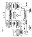
- the structure of the classification algorithm is shown in Figure 6.
- the algorithm is based upon a hierarchical approach for detecting welding defects as soon as possible.
- the rectangular boxes refer to activities of signal treatment where techniques of extraction of the characteristics are applied, whilst the blocks highlighted by an elliptical outline represent classification modules.
- the classifications of the power signal and of the depth of penetration are made independently, and only after their processing is the detection of the errors of assembly made. If a sample is classified as "correctly assembled", there can then be activated the subsequent module for monitoring the possible presence of porosities.
- the next step is to develop the classifier, which, by processing the characteristics, implements the final quality analysis.
- Possible techniques of classification include the so-called “k-nearest neighbour rule” (see, for example, B. D. Ripley, “Pattern Recognition and Neural Networks", Cambridge University Press, 1996) or neural networks of the "feed-forward” type.
Landscapes
- Engineering & Computer Science (AREA)
- Physics & Mathematics (AREA)
- Optics & Photonics (AREA)
- Plasma & Fusion (AREA)
- Mechanical Engineering (AREA)
- Health & Medical Sciences (AREA)
- Life Sciences & Earth Sciences (AREA)
- Nuclear Medicine, Radiotherapy & Molecular Imaging (AREA)
- Quality & Reliability (AREA)
- Chemical & Material Sciences (AREA)
- Analytical Chemistry (AREA)
- Biochemistry (AREA)
- General Health & Medical Sciences (AREA)
- General Physics & Mathematics (AREA)
- Immunology (AREA)
- Pathology (AREA)
- Laser Beam Processing (AREA)
- Bending Of Plates, Rods, And Pipes (AREA)
- Investigating Materials By The Use Of Optical Means Adapted For Particular Applications (AREA)
Abstract
Description
- The subject of the present invention is a system and a method for monitoring laser welds according to the preambles of, respectively, claims 1 and 13 (see, for example, the article "Aspects of quality assurance with plasma monitoring system during laser beam welding" by K. ZIMMERMANN et al, in LASER IN DER TECHNIK, 1994, pp 503-510).
- Prompt detection of defects in industrial processes has become crucial on account of its impact on the analysis of product quality, as well as on the industrial process itself. Automated laser welding has in recent years witnessed an increasing diffusion in particular on account of its versatility, which enables joins to be made between metals or non-metals at a high speed, with a relatively low supply of heat. Laser technology makes possible the production of welds in an open-air environment, or in vacuum conditions, or in a controlled atmosphere, or again in pressurized chambers, with a highly automated and reliable process. In addition, a laser beam can be focused on very small areas. In general, the analysis of the quality of the process is entrusted to off-line visual inspection of each welded component. Said inspection step constitutes an activity which involves considerable waste of time and which rarely provides the operator with useful indications on how the process itself may be perfected, for example by refining some of its parameters. In addition, external visual inspection of the welded products entails a costly procedure, which is more often than not carried out using ultrasound devices. A different approach consists in providing for an on-line analysis of quality performed directly during the process. The systems of this type so far produced are, however, able to identify only some of the possible welding defects, and moreover in a way that is rather unsatisfactory, as well as being somewhat insensitive to the different set-ups of the laser device. A further drawback of currently available systems lies in the fact that they are based upon reference signals indicating an optimal process or, in some cases, a process presenting defects, and compare the signal associated to the actual process with the aforesaid specially constructed reference signals. The major problem of such systems is that they involve the use of a number of reference signals which ranges from a minimum of two to more than ten. The preparation of such reference signals poses various problems. In the first place, preparing a certain number of repeatable references entails the presence of a skilled operator who is able to certify the goodness of the process. In addition, for certain applications, the creation of even just two references leads to a waste of material. Finally, there is the difficulty of obtaining references associated to a process that presents defects.
- In order to understand the purposes and characteristics of the present invention, it is first necessary to make a number of basic considerations on the characteristics of a laser-welding process.
- The phenomenon of welding may be defined as the localized coalescence of metals or non-metals produced by heat and/or pressure. A laser beam can be focused in very small areas. The concentration of power enables the welding process to be achieved. Since a laser beam is a beam made up of light radiation, the reflecting properties of the metals determine which part of the beam is to be reflected, so that even a large part of the incident power can bounce back. This problem is increased by the fact that the majority of industrial lasers emit infrared light, which is reflected by metals even better than is visible light. This situation changes drastically when the surface of the structure subjected to welding starts to melt. The liquid metals absorb much more power from the incident radiation as compared to solid metals, so that the flow of heat absorbed increases suddenly, thus raising the temperature of the metal above the boiling point and generating metal vapour. The pressure of this vapour opens a narrow and deep channel around the laser beam, so forming a melted area having a keyhole-like profile (the so-called "keyhole"). The ratio between the depth and width of the laser-welding areas shaped like a keyhole may reach values of up to 10:1 but is more commonly in the region of 4:1. Keyhole welding is a threshold process: when the incident radiation is low, little power is absorbed; once the radiation becomes high enough to form a keyhole, the majority of the power is absorbed by the welded component. Small variations of power in the proximity of the threshold of the keyhole cause very considerable changes in the quality of the weld.
- Laser devices have the appreciable property of producing thin and deep welds, so that it is common to adopt a butt-welding configuration. Said configuration makes possible a high welding speed and requires a low supply of heat since all the metal of the weld is used in the joint. Also irrespective of said configuration, in laser welding the correct coupling of the elements to be welded in the area of the joint is critical. Almost all laser welds are autogenous; i.e., no weld material is used. Any space left in the area of the joint can become a void in the welded product obtained. Even assuming that the voids are acceptable, it should be considered that a focused laser beam can pass through a butt joint in which a space of 0.2 mm has been left without causing any welding. The beam simply bounces off the facing walls of the elements to be welded and exits on the opposite side.
- Furthermore, the material to be welded must be clean. Any non-metallic contaminant is ejected from the keyhole, producing splashes, porosities and the risk of damage to the focusing optical devices.
- From document US-B1-6 399 915 it is known a method for monitoring weld quality measuring the radiation emitted by the weld pool, that also measures the reflected laser radiation through two photodiodes placed at different angles. The method also provides for analyzing the DC or low frequency component and the high frequency component of the sensor signals as a a function of different parameters. The quality of the weld is established on the basis of parameters extracted from such signals.
- The process according to the invention is aimed at detecting in particular the following defects of the laser weld:
- insufficient depth of penetration;
- misalignments of the coupling during assembly of the pieces;
- presence of porosities;
- reductions in the level of power of the laser source; and
- drops in power of the laser source.
- The purpose of the present invention is to provide a monitoring system and method which will be able to recognize accurately all the aforesaid defects through a process which can be carried out also on line and in real time.
In order to achieve the above purpose, the subject of the invention is a system and a method for monitoring laser welds as defined inclaims 1 and 13 respectively. - The invention will now be described with reference to the annexed drawings, which are provided purely by way of non-limiting example and in which:
- Figure 1 illustrates a diagram of an embodiment of the system according to the invention;
- Figure 2 is a block diagram which indicates the main steps of the method according to the invention;
- Figures 3, 4 and 5 illustrate diagrams which show the characteristics of the signals at output from the sensor means of the system according to the invention; and
- Figure 6 is a more detailed block diagram illustrating a preferred mode of embodiment of the method according to the invention.
- In Figure 1, the
reference number 1 designates the head of a focusing laser (illustrated only schematically), which focuses alaser beam 2 on a structure to be welded 3, for example by means of two successive reflections from a half-silvered mirror 4 and aconventional mirror 5. There is envisaged a relative movement of the focusing system with respect to thestructure 3, for example in order to create a welding line 6. In a preferred embodiment, the half-silvered mirror 4 is a zinc-selenium mirror with an absorption of 0.2%. The radiation reflected by thestructure 3 undergoing welding is again reflected by themirror 5 towards the half-silvered mirror 4, passes through the latter and is focused by a filtering lens 7 on aphotodiode sensor 8. The signal at output from thesensor 8 is sent to an electronic processing unit 9, which displays at oneoutput 10 the quality of the weld. The processing unit 9 can comprise, for example, a data-acquisition card, of the NI 6110E PC card type, with an acquisition frequency of 5 Msamples per sec, as well as a plurality of personal computers, for example of the 800-MHz Pentium III type. Analysis of the quality of the weld obtained using the system according to the invention is based not only upon the signal at output from thephotodiode 8, which is linked to the radiation produced by the welding process and comes from the structure to be welded, but also upon the signal indicating the grid current of the laser, which is linked to the power of the laser and which also comes from the component welded. The grid-current signal is used for identifying reductions in the level of power of the laser source and drops in power of the laser source. The signal coming from the photodiode is used for identifying possible defects, such as insufficient depth of penetration, misalignments in the coupling of the pieces, or porosities. - As may be seen in Figure 2, the first step of the procedure of processing downstream of sampling of the signals is a lowpass pre-filtering step, necessary for reducing the high-frequency noise typically present in the industrial context. The appropriate filtering frequency is established by means of a spectral analysis, which identifies the higher-frequency components of the signals. Subsequently, an operation of down-sampling is carried out in order to reduce the cardinality of the set of data, with the intent of speeding up the operation of extraction of the characteristics of the signals and the subsequent classification. The ratio of down-sampling is identified downstream, after prior definition of a maximum tolerable limit for the execution of the procedure. On the signal filtered and appropriately decimated it is necessary to extract a set of characteristics, which, by describing in a compact way the nature of the process, will enable resolution of the application of analysis of the quality of the weld. The step of extraction of the characteristics from the signals is based upon generation of a function that interpolates the signal and subsequent extraction of appropriate indices of deviation. Examples of index of deviation extracted from the signals involved in the process in question are:
- for the power signal (Figure 3) :
- mean intensity A and duration T of the useful part of the signal,
- maximum positive deviation F1 and maximum negative deviation F2 per signal with respect to its mean value,
- fluctuation of maximum power during welding Fmax;
- for the signal of the photodiode (Figures 4 and 5) :
- mean intensity and variance;
- time durations Ti and corresponding amplitudes Ai of the main deviations between signal and interpolated reference signal;
- differences between the co-ordinates of the minimum and of the maximum taken on the interpolating curve: characteristic D and H.
- The final step of the algorithm entails the construction of a classifier, which, by receiving at input the characteristics identified (or a subset thereof) evaluates the quality of the weld as: "correct" / "incorrect" / "insufficient penetration" / "discontinuous laser power" / "incorrect assembly" / "porosity".
- The structure of the classification algorithm is shown in Figure 6. The algorithm is based upon a hierarchical approach for detecting welding defects as soon as possible. The rectangular boxes refer to activities of signal treatment where techniques of extraction of the characteristics are applied, whilst the blocks highlighted by an elliptical outline represent classification modules. The classifications of the power signal and of the depth of penetration are made independently, and only after their processing is the detection of the errors of assembly made. If a sample is classified as "correctly assembled", there can then be activated the subsequent module for monitoring the possible presence of porosities. Once the important characteristics have been identified, the next step is to develop the classifier, which, by processing the characteristics, implements the final quality analysis. Possible techniques of classification that may be used include the so-called "k-nearest neighbour rule" (see, for example, B. D. Ripley, "Pattern Recognition and Neural Networks", Cambridge University Press, 1996) or neural networks of the "feed-forward" type.
- Of course, without prejudice to the principle of the invention, the details of construction and the embodiments may vary widely with respect to what is described and illustrated herein purely by way of example, without thereby departing from the scope of the present invention as defined in the appended claims.
Claims (18)
- A system for monitoring laser welds, comprising:- laser-welding means (1, 4, 5), for focusing a laser beam (2) on a structure (3) to be welded;- sensor means (8), designed for detecting the radiation produced in the welding area and for emitting signals indicating said radiation;
means for emitting signals linked to the power of the laser beam; and- processing means (9) for processing the aforesaid signals at output from said sensor means (8) and said means for emitting signals linked to the power of the laser beam, said processing means (9) being provided for:- extracting given quality characteristics of the signal coming from the sensor means (8) by means of generation of a function that interpolates the signal and subsequent extraction of indices of deviation of the signal with respect to the interpolating function; and- classifying the quality characteristics extracted, giving an indication of the quality of the weld:
characterized in that
said means for emitting signals linked to the power of the laser beam exploit the grid current of the laser; said processing means (9) are further provided for:extracting given power characteristics from the signals linked to the power of the laser beam by means of generation of a function interpolating the signal and subsequent extraction of indices of deviation of the signal with respect to the interpolating function, wherein the extracting and classifying steps of the signal, to give an indication of the quality of the weld, are performed in the following hierarchical way:i- extracting and classifying in an independant way the power signal;ii- extracting and classifying in an independant way the depth of penetration based on the welding signal, and comparing this result with the result of the classification of the power signal;iii- filtering, processing, extracting and classifying the assembly and comparing this result with the result of the previous comparison achieved in steps i- and ii-;iv- filtering, processing, extracting and classifying the porosities and comparing this result with the result of the previous comparison achieved in step iii-;v- producing a final statement on the weld quality according to the result of the comparison steps achieved in step iv-. - The system according to Claim 1, characterized in that it comprises a lowpass filter for filtering the signal emitted by the sensor means prior to its processing.
- The system according to Claim 1, characterized in that the processing means (9) are designed for executing a down-sampling operation.
- The system according to Claim 1, characterized in that the aforesaid processing means (9) are designed for filtering one or more indices of deviation from the signal indicating the power of the laser beam, chosen from among: mean intensity (A) and duration (T) of the useful part of the signal, maximum positive deviation (F1) and maximum negative deviation (F2) of the signal with respect to its mean value, and fluctuation of maximum power during the weld (Fmax).
- The system according to Claim 1, characterized in that said processing means are designed for extracting one or more indices of deviation from the signal emitted by the aforesaid sensor means (8) and indicating the characteristics of the radiation reflected by the structure being welded, chosen from among: mean intensity and variance, time durations (Ti) and corresponding amplitudes (Ai) of the principal deviations between signal and interpolated reference signal, and differences between the co-ordinates of the minimum and of the maximum taken on the interpolating curve (characteristics D and H).
- The system according to Claim 1, characterized in that the laser-welding means comprise: a focusing head (1); and an optical system for directing the laser beam focused on the component to be welded, which includes a half-silvered mirror (4), which has the purpose of reflecting, in the direction of the structure that is to be welded, the laser beam coming from the focusing head (1), of receiving in return the radiation reflected from the structure being welded, and of transmitting said radiation (which passes through the half-silvered mirror (4) itself) to the aforesaid sensor means (8), said sensor means (8) being set behind the aforesaid half-silvered mirror (4).
- The system according to Claim 6, characterized in that the aforesaid sensor means are formed by a photodiode (8).
- The system according to Claim 7, characterized in that the half-silvered mirror (4) consists of a zinc-selenium optical element.
- The system according to Claim B, characterized in that the half-silvered mirror has a factor of absorption equal to approximately 0-2%.
- The system according to Claim 7, characterized in that the aforesaid photodiode (8) has a spectral response substantially equal to 190-1100 nm.
- The system according to Claim 10, characterized in that between the half-silvered mirror (4) and the photodiode (9) is interposed an optical filter (7), which has an optical band substantially comprised between 200 nm and 405 nm for selection of the radiation coming from the structure being welded.
- The system according to Claim 1, characterized in that the aforesaid processing means (9) comprise an NI 6110E data-acquisition PC card, with frequencies of acquisition of 5 Msamples per sec, as well as a plurality of personal computers.
- A method for monitoring laser welds, comprising the steps of:- focusing a laser beam (2) on a structure (3) to be welded;- detecting the radiation produced in the welding area and generating signals indicating said radiation; and- emitting signals linked to the power of the laser beam- processing the aforesaid signals,- extracting given quality characteristics of the aforesaid signal by means of generation of a function that interpolates the signal, and subsequent extraction of indices of deviation of the signal with respect to the interpolating function; and- classifying the characteristics extracted, giving an indication of the quality of the weld.
characterized in that
said emitting signals linked to the power of the laser beam includes exploiting the grid current of the laser; and
said processing further includes:extracting given power characteristics from the signals linked to the laser beam power by means of generation of a function interpolating the signal and subsequent extraction of indices of deviation of the signal with respect to the interpolating function wherein the extracting and classifying steps of the signal, to give an indication of the quality of the weld, are performed in the following hierarchical way:i- extracting and classifying in an independant way the power signal;ii- extracting and classifying in an independant way the depth of penetration based on the welding signal, and comparing this result with the result of the classification of the power signal;iii- filtering, processing, extracting and classifying the assembly and comparing this result with the result of the previous comparison achieved in steps i- and ii-;iv- filtering, processing, extracting and classifying the porosities and comparing this result with the result of the previous comparison achieved in step iii-;v- producing a final statement on the weld quality according to the result of the comparison steps achieved in step iv-; - The method according to Claim 13, characterized in that the aforesaid signal is pre-filtered before being processed.
- The method according to Claim 13, characterized in that, before the processing of the aforesaid signal, there is performed the operation of down-sampling.
- The method according to Claim 13, characterized in that one or more indices of deviation of the signal indicating the power of the laser beam are extracted, chosen from among: mean intensity (A) and duration (T) of the useful part of the signal, maximum positive deviation (F1) and maximum negative deviation (F2) of the signal with respect to its mean value, maximum power fluctuation during welding (Fmax).
- The method according to Claim 13, characterized in that one or more indices of deviation of the signal indicating the characteristics of the reflected radiation are extracted, chosen from among: mean intensity and variance, time durations (Ti) and corresponding amplitudes (Ai) of the main deviations between signal and interpolated reference signal, differences between the co-ordinates of the minimum and the maximum taken on the interpolating curve (characteristics D and H).
- The method according to Claim 13, characterized in that said quality characteristics and power characteristic classifiying operations are included in a final step of construction of a classifier for supplying at output further indications of the quality of the weld, for example chosen from among: correct weld, incorrect weld, discontinuous laser power, incorrect assembly of the elements to be welded.
Applications Claiming Priority (2)
| Application Number | Priority Date | Filing Date | Title |
|---|---|---|---|
| IT2002TO000508A ITTO20020508A1 (en) | 2002-06-14 | 2002-06-14 | LASER WELDING MONITORING SYSTEM AND PROCEDURE |
| ITTO20020508 | 2002-06-14 |
Publications (2)
| Publication Number | Publication Date |
|---|---|
| EP1371443A1 EP1371443A1 (en) | 2003-12-17 |
| EP1371443B1 true EP1371443B1 (en) | 2006-01-04 |
Family
ID=11459404
Family Applications (1)
| Application Number | Title | Priority Date | Filing Date |
|---|---|---|---|
| EP03009130A Expired - Lifetime EP1371443B1 (en) | 2002-06-14 | 2003-04-22 | A system and method for monitoring laser welds and giving an indication of the quality of welding |
Country Status (6)
| Country | Link |
|---|---|
| EP (1) | EP1371443B1 (en) |
| AT (1) | ATE314900T1 (en) |
| DE (1) | DE60303058T2 (en) |
| DK (1) | DK1371443T3 (en) |
| ES (1) | ES2253599T3 (en) |
| IT (1) | ITTO20020508A1 (en) |
Cited By (4)
| Publication number | Priority date | Publication date | Assignee | Title |
|---|---|---|---|---|
| EP2062675A1 (en) | 2007-11-20 | 2009-05-27 | Trumpf Werkzeugmaschinen GmbH + Co. KG | Method for determining a parameter for seam position regulation precision |
| US10101201B2 (en) | 2013-11-13 | 2018-10-16 | Medtronic, Inc. | System for continuous laser beam monitoring and analysis |
| EP4506668A4 (en) * | 2023-06-21 | 2025-05-07 | Contemporary Amperex Technology (Hong Kong) Limited | Method for measuring power of welding laser, and laser welding system |
| EP4372333A4 (en) * | 2022-07-01 | 2025-05-14 | Contemporary Amperex Technology (Hong Kong) Limited | Laser power measurement system, welding system, and testing method for laser-welded workpiece |
Families Citing this family (13)
| Publication number | Priority date | Publication date | Assignee | Title |
|---|---|---|---|---|
| ITTO20040013A1 (en) * | 2004-01-13 | 2004-04-13 | Fiat Ricerche | PROCEDURE FOR THE QUALITY CONTROL OF INDUSTRIAL PROCESSES IN PARTICULAR LASER WELDING PROCESSES |
| EP1634672B1 (en) | 2004-09-14 | 2009-03-18 | C.R.F. Società Consortile per Azioni | System for monitoring the quality of industrial processes and method therefrom |
| EP1677170A1 (en) | 2004-12-30 | 2006-07-05 | C.R.F. Società Consortile per Azioni | Module with sensor means for monitoring industrial processes |
| US8162020B2 (en) * | 2005-08-24 | 2012-04-24 | Battery Patent Trust | Infra-red thermal imaging of laser welded battery module enclosure components |
| AU2009316991B2 (en) | 2008-11-19 | 2013-08-29 | Bae Systems Plc | Mirror structure |
| AU2009316985B9 (en) | 2008-11-19 | 2014-02-27 | Bae Systems Plc | Mirror structure |
| ITTO20090158U1 (en) | 2009-11-02 | 2011-05-03 | Fiat Ricerche | MONITORING MODULE OF INDUSTRIAL PROCESSES |
| KR101240980B1 (en) | 2010-11-18 | 2013-03-11 | 기아자동차주식회사 | Method for checking quality of laser welding and equipment thereof |
| DE102011078276C5 (en) | 2011-06-29 | 2014-04-03 | Trumpf Laser- Und Systemtechnik Gmbh | Method for detecting errors during a laser machining process and laser machining apparatus |
| KR101670155B1 (en) * | 2012-05-15 | 2016-10-27 | 도요타지도샤가부시키가이샤 | Welding method, welding device, and battery manufacturing method |
| CN104634781A (en) * | 2015-02-07 | 2015-05-20 | 石河子大学 | Online detection device of delinting cotton seed processing line |
| IT201800021022A1 (en) * | 2018-12-24 | 2020-06-24 | Comau Spa | "Procedure for monitoring the quality of a weld, relative welding station and IT product" |
| CN114523201A (en) * | 2022-01-31 | 2022-05-24 | 扬州市恒泰人防设备有限公司 | Full-automatic laser welding system of emergency exit |
Citations (1)
| Publication number | Priority date | Publication date | Assignee | Title |
|---|---|---|---|---|
| EP1361501A2 (en) * | 1995-02-28 | 2003-11-12 | Texas Instruments Incorporated | Power conservation and thermal management arrangements for computers |
Family Cites Families (6)
| Publication number | Priority date | Publication date | Assignee | Title |
|---|---|---|---|---|
| JPH0785128B2 (en) * | 1986-01-14 | 1995-09-13 | 三晃技研工業株式会社 | Method and device for inspecting inner wall of pore |
| AT399117B (en) * | 1991-05-27 | 1995-03-27 | Schuoecker Dieter Dipl Ing Dr | Method for the automated quality control of laser machining |
| US5728992A (en) * | 1996-02-29 | 1998-03-17 | Westinghouse Electric Corporation | Apparatus and method for real time evaluation of laser welds especially in confined spaces such as within heat exchanger tubing |
| AU2087400A (en) * | 1999-01-14 | 2000-08-01 | Powerlasers Limited | Method for laser processing fault detection |
| JP3560135B2 (en) * | 1999-03-23 | 2004-09-02 | 日産自動車株式会社 | Quality monitoring method for YAG laser welds |
| ITMI20011506A1 (en) * | 2001-07-13 | 2003-01-13 | Salvagnini Italia Spa | QUALITY CONTROL SYSTEM FOR A LASER CUT OR DRILLING, IN PARTICULAR FOR SHEET METAL SHEETS |
-
2002
- 2002-06-14 IT IT2002TO000508A patent/ITTO20020508A1/en unknown
-
2003
- 2003-04-22 AT AT03009130T patent/ATE314900T1/en active
- 2003-04-22 DE DE60303058T patent/DE60303058T2/en not_active Expired - Lifetime
- 2003-04-22 ES ES03009130T patent/ES2253599T3/en not_active Expired - Lifetime
- 2003-04-22 DK DK03009130T patent/DK1371443T3/en active
- 2003-04-22 EP EP03009130A patent/EP1371443B1/en not_active Expired - Lifetime
Patent Citations (1)
| Publication number | Priority date | Publication date | Assignee | Title |
|---|---|---|---|---|
| EP1361501A2 (en) * | 1995-02-28 | 2003-11-12 | Texas Instruments Incorporated | Power conservation and thermal management arrangements for computers |
Cited By (4)
| Publication number | Priority date | Publication date | Assignee | Title |
|---|---|---|---|---|
| EP2062675A1 (en) | 2007-11-20 | 2009-05-27 | Trumpf Werkzeugmaschinen GmbH + Co. KG | Method for determining a parameter for seam position regulation precision |
| US10101201B2 (en) | 2013-11-13 | 2018-10-16 | Medtronic, Inc. | System for continuous laser beam monitoring and analysis |
| EP4372333A4 (en) * | 2022-07-01 | 2025-05-14 | Contemporary Amperex Technology (Hong Kong) Limited | Laser power measurement system, welding system, and testing method for laser-welded workpiece |
| EP4506668A4 (en) * | 2023-06-21 | 2025-05-07 | Contemporary Amperex Technology (Hong Kong) Limited | Method for measuring power of welding laser, and laser welding system |
Also Published As
| Publication number | Publication date |
|---|---|
| ITTO20020508A1 (en) | 2003-12-15 |
| ATE314900T1 (en) | 2006-02-15 |
| EP1371443A1 (en) | 2003-12-17 |
| DE60303058T2 (en) | 2006-07-27 |
| DE60303058D1 (en) | 2006-03-30 |
| ITTO20020508A0 (en) | 2002-06-14 |
| ES2253599T3 (en) | 2006-06-01 |
| DK1371443T3 (en) | 2006-05-22 |
Similar Documents
| Publication | Publication Date | Title |
|---|---|---|
| EP1371443A1 (en) | A system and method for monitoring laser welds and giving an indication of the quality of welding | |
| CN100475414C (en) | Real time monitoring device of the three-dimensional laser beam welding and incising process | |
| You et al. | Multisensor fusion system for monitoring high-power disk laser welding using support vector machine | |
| CN115889975B (en) | Laser welding process monitoring system and method | |
| KR101240980B1 (en) | Method for checking quality of laser welding and equipment thereof | |
| EP3426428B1 (en) | Apparatus and method for controlling laser processing of a material | |
| JPH08192283A (en) | Laser processing equipment | |
| CN115697610A (en) | Method for analyzing laser processing process, system for analyzing laser processing process, and laser processing system having the same | |
| EP2605882B1 (en) | Method of and fibre laser for optimising the focus of the fibre laser | |
| JPH06252485A (en) | Laser processing machine | |
| US12214444B2 (en) | Methods and devices for monitoring a welding process for welding glass workpieces | |
| FR2811427A1 (en) | METHOD FOR DETECTION AND IDENTIFICATION OF DEFECTS IN A WELDING CORD MADE BY LASER BEAM | |
| JP2014226728A (en) | Method and device for identifying incomplete cut | |
| Nadipalli et al. | Considerations for interpreting in-situ photodiode sensor data in pulsed mode laser powder bed fusion | |
| Kratzsch et al. | Coaxial process control during laser beam welding of tailored blanks | |
| Zeng et al. | Online identification of laser welding penetration through multi-photoelectric decomposition-reconstruction and shifted-windows-based transformer deep learning framework | |
| Shevchik et al. | Acoustic emission for in situ monitoring of laser processing | |
| JP3184962B2 (en) | Laser welding detection method | |
| Abels et al. | Universal coaxial process control system for laser materials processing | |
| EP1361015A1 (en) | System and method for monitoring laser welds, particularly in tailored blanks | |
| Sichani et al. | Monitoring and adaptive control of CO2 laser flame cutting | |
| US20250100079A1 (en) | Method for Pretreating a Surface of a Workpiece | |
| Duflou et al. | Development of a real time monitoring and adaptive control system for laser flame cutting | |
| Oezmert et al. | Detectability of penetration based on weld pool geometry and process emission spectrum in laser welding of copper | |
| JP3136556B2 (en) | Laser welding machine |
Legal Events
| Date | Code | Title | Description |
|---|---|---|---|
| PUAI | Public reference made under article 153(3) epc to a published international application that has entered the european phase |
Free format text: ORIGINAL CODE: 0009012 |
|
| AK | Designated contracting states |
Kind code of ref document: A1 Designated state(s): AT BE BG CH CY CZ DE DK EE ES FI FR GB GR HU IE IT LI LU MC NL PT RO SE SI SK TR |
|
| AX | Request for extension of the european patent |
Extension state: AL LT LV MK |
|
| 17P | Request for examination filed |
Effective date: 20040528 |
|
| 17Q | First examination report despatched |
Effective date: 20040623 |
|
| AKX | Designation fees paid |
Designated state(s): AT BE BG CH CY CZ DE DK EE ES FI FR GB GR HU IE IT LI LU MC NL PT RO SE SI SK TR |
|
| GRAP | Despatch of communication of intention to grant a patent |
Free format text: ORIGINAL CODE: EPIDOSNIGR1 |
|
| GRAS | Grant fee paid |
Free format text: ORIGINAL CODE: EPIDOSNIGR3 |
|
| GRAA | (expected) grant |
Free format text: ORIGINAL CODE: 0009210 |
|
| AK | Designated contracting states |
Kind code of ref document: B1 Designated state(s): AT BE BG CH CY CZ DE DK EE ES FI FR GB GR HU IE IT LI LU MC NL PT RO SE SI SK TR |
|
| PG25 | Lapsed in a contracting state [announced via postgrant information from national office to epo] |
Ref country code: NL Free format text: LAPSE BECAUSE OF FAILURE TO SUBMIT A TRANSLATION OF THE DESCRIPTION OR TO PAY THE FEE WITHIN THE PRESCRIBED TIME-LIMIT Effective date: 20060104 Ref country code: SK Free format text: LAPSE BECAUSE OF FAILURE TO SUBMIT A TRANSLATION OF THE DESCRIPTION OR TO PAY THE FEE WITHIN THE PRESCRIBED TIME-LIMIT Effective date: 20060104 Ref country code: SI Free format text: LAPSE BECAUSE OF FAILURE TO SUBMIT A TRANSLATION OF THE DESCRIPTION OR TO PAY THE FEE WITHIN THE PRESCRIBED TIME-LIMIT Effective date: 20060104 Ref country code: BE Free format text: LAPSE BECAUSE OF FAILURE TO SUBMIT A TRANSLATION OF THE DESCRIPTION OR TO PAY THE FEE WITHIN THE PRESCRIBED TIME-LIMIT Effective date: 20060104 Ref country code: FI Free format text: LAPSE BECAUSE OF FAILURE TO SUBMIT A TRANSLATION OF THE DESCRIPTION OR TO PAY THE FEE WITHIN THE PRESCRIBED TIME-LIMIT Effective date: 20060104 Ref country code: RO Free format text: LAPSE BECAUSE OF FAILURE TO SUBMIT A TRANSLATION OF THE DESCRIPTION OR TO PAY THE FEE WITHIN THE PRESCRIBED TIME-LIMIT Effective date: 20060104 |
|
| REG | Reference to a national code |
Ref country code: GB Ref legal event code: FG4D |
|
| REG | Reference to a national code |
Ref country code: CH Ref legal event code: EP |
|
| REG | Reference to a national code |
Ref country code: IE Ref legal event code: FG4D |
|
| REG | Reference to a national code |
Ref country code: CH Ref legal event code: NV Representative=s name: ISLER & PEDRAZZINI AG |
|
| REG | Reference to a national code |
Ref country code: SE Ref legal event code: TRGR |
|
| REF | Corresponds to: |
Ref document number: 60303058 Country of ref document: DE Date of ref document: 20060330 Kind code of ref document: P |
|
| PG25 | Lapsed in a contracting state [announced via postgrant information from national office to epo] |
Ref country code: BG Free format text: LAPSE BECAUSE OF FAILURE TO SUBMIT A TRANSLATION OF THE DESCRIPTION OR TO PAY THE FEE WITHIN THE PRESCRIBED TIME-LIMIT Effective date: 20060404 |
|
| PG25 | Lapsed in a contracting state [announced via postgrant information from national office to epo] |
Ref country code: IE Free format text: LAPSE BECAUSE OF NON-PAYMENT OF DUE FEES Effective date: 20060424 |
|
| PG25 | Lapsed in a contracting state [announced via postgrant information from national office to epo] |
Ref country code: MC Free format text: LAPSE BECAUSE OF NON-PAYMENT OF DUE FEES Effective date: 20060430 |
|
| REG | Reference to a national code |
Ref country code: GR Ref legal event code: EP Ref document number: 20060400659 Country of ref document: GR |
|
| REG | Reference to a national code |
Ref country code: DK Ref legal event code: T3 |
|
| REG | Reference to a national code |
Ref country code: ES Ref legal event code: FG2A Ref document number: 2253599 Country of ref document: ES Kind code of ref document: T3 |
|
| PG25 | Lapsed in a contracting state [announced via postgrant information from national office to epo] |
Ref country code: PT Free format text: LAPSE BECAUSE OF FAILURE TO SUBMIT A TRANSLATION OF THE DESCRIPTION OR TO PAY THE FEE WITHIN THE PRESCRIBED TIME-LIMIT Effective date: 20060605 |
|
| NLV1 | Nl: lapsed or annulled due to failure to fulfill the requirements of art. 29p and 29m of the patents act | ||
| ET | Fr: translation filed | ||
| PLBE | No opposition filed within time limit |
Free format text: ORIGINAL CODE: 0009261 |
|
| STAA | Information on the status of an ep patent application or granted ep patent |
Free format text: STATUS: NO OPPOSITION FILED WITHIN TIME LIMIT |
|
| 26N | No opposition filed |
Effective date: 20061005 |
|
| REG | Reference to a national code |
Ref country code: CH Ref legal event code: PCAR Free format text: ISLER & PEDRAZZINI AG;POSTFACH 1772;8027 ZUERICH (CH) |
|
| PG25 | Lapsed in a contracting state [announced via postgrant information from national office to epo] |
Ref country code: CZ Free format text: LAPSE BECAUSE OF FAILURE TO SUBMIT A TRANSLATION OF THE DESCRIPTION OR TO PAY THE FEE WITHIN THE PRESCRIBED TIME-LIMIT Effective date: 20060104 |
|
| PG25 | Lapsed in a contracting state [announced via postgrant information from national office to epo] |
Ref country code: EE Free format text: LAPSE BECAUSE OF FAILURE TO SUBMIT A TRANSLATION OF THE DESCRIPTION OR TO PAY THE FEE WITHIN THE PRESCRIBED TIME-LIMIT Effective date: 20060104 |
|
| PG25 | Lapsed in a contracting state [announced via postgrant information from national office to epo] |
Ref country code: HU Free format text: LAPSE BECAUSE OF FAILURE TO SUBMIT A TRANSLATION OF THE DESCRIPTION OR TO PAY THE FEE WITHIN THE PRESCRIBED TIME-LIMIT Effective date: 20060705 Ref country code: LU Free format text: LAPSE BECAUSE OF NON-PAYMENT OF DUE FEES Effective date: 20060422 Ref country code: TR Free format text: LAPSE BECAUSE OF FAILURE TO SUBMIT A TRANSLATION OF THE DESCRIPTION OR TO PAY THE FEE WITHIN THE PRESCRIBED TIME-LIMIT Effective date: 20060104 |
|
| PG25 | Lapsed in a contracting state [announced via postgrant information from national office to epo] |
Ref country code: CY Free format text: LAPSE BECAUSE OF FAILURE TO SUBMIT A TRANSLATION OF THE DESCRIPTION OR TO PAY THE FEE WITHIN THE PRESCRIBED TIME-LIMIT Effective date: 20060104 |
|
| PG25 | Lapsed in a contracting state [announced via postgrant information from national office to epo] |
Ref country code: IT Free format text: LAPSE BECAUSE OF NON-PAYMENT OF DUE FEES Effective date: 20090422 |
|
| PGFP | Annual fee paid to national office [announced via postgrant information from national office to epo] |
Ref country code: GR Payment date: 20110310 Year of fee payment: 9 |
|
| PGFP | Annual fee paid to national office [announced via postgrant information from national office to epo] |
Ref country code: SE Payment date: 20110412 Year of fee payment: 9 Ref country code: CH Payment date: 20110412 Year of fee payment: 9 Ref country code: ES Payment date: 20110518 Year of fee payment: 9 |
|
| PGRI | Patent reinstated in contracting state [announced from national office to epo] |
Ref country code: IT Effective date: 20110616 |
|
| PGFP | Annual fee paid to national office [announced via postgrant information from national office to epo] |
Ref country code: AT Payment date: 20110328 Year of fee payment: 9 Ref country code: GB Payment date: 20110420 Year of fee payment: 9 Ref country code: DK Payment date: 20110412 Year of fee payment: 9 |
|
| REG | Reference to a national code |
Ref country code: DK Ref legal event code: EBP |
|
| REG | Reference to a national code |
Ref country code: CH Ref legal event code: PL |
|
| REG | Reference to a national code |
Ref country code: SE Ref legal event code: EUG |
|
| REG | Reference to a national code |
Ref country code: AT Ref legal event code: MM01 Ref document number: 314900 Country of ref document: AT Kind code of ref document: T Effective date: 20120422 |
|
| GBPC | Gb: european patent ceased through non-payment of renewal fee |
Effective date: 20120422 |
|
| REG | Reference to a national code |
Ref country code: GR Ref legal event code: ML Ref document number: 20060400659 Country of ref document: GR Effective date: 20121102 |
|
| PG25 | Lapsed in a contracting state [announced via postgrant information from national office to epo] |
Ref country code: CH Free format text: LAPSE BECAUSE OF NON-PAYMENT OF DUE FEES Effective date: 20120430 Ref country code: LI Free format text: LAPSE BECAUSE OF NON-PAYMENT OF DUE FEES Effective date: 20120430 Ref country code: AT Free format text: LAPSE BECAUSE OF NON-PAYMENT OF DUE FEES Effective date: 20120422 Ref country code: GB Free format text: LAPSE BECAUSE OF NON-PAYMENT OF DUE FEES Effective date: 20120422 |
|
| PG25 | Lapsed in a contracting state [announced via postgrant information from national office to epo] |
Ref country code: GR Free format text: LAPSE BECAUSE OF NON-PAYMENT OF DUE FEES Effective date: 20121102 Ref country code: SE Free format text: LAPSE BECAUSE OF NON-PAYMENT OF DUE FEES Effective date: 20120423 |
|
| REG | Reference to a national code |
Ref country code: ES Ref legal event code: FD2A Effective date: 20131023 |
|
| PG25 | Lapsed in a contracting state [announced via postgrant information from national office to epo] |
Ref country code: DK Free format text: LAPSE BECAUSE OF NON-PAYMENT OF DUE FEES Effective date: 20120430 |
|
| PG25 | Lapsed in a contracting state [announced via postgrant information from national office to epo] |
Ref country code: ES Free format text: LAPSE BECAUSE OF NON-PAYMENT OF DUE FEES Effective date: 20120423 |
|
| REG | Reference to a national code |
Ref country code: FR Ref legal event code: PLFP Year of fee payment: 14 |
|
| REG | Reference to a national code |
Ref country code: FR Ref legal event code: PLFP Year of fee payment: 15 |
|
| REG | Reference to a national code |
Ref country code: FR Ref legal event code: PLFP Year of fee payment: 16 |
|
| PGFP | Annual fee paid to national office [announced via postgrant information from national office to epo] |
Ref country code: FR Payment date: 20180502 Year of fee payment: 16 Ref country code: IT Payment date: 20180416 Year of fee payment: 16 |
|
| PGFP | Annual fee paid to national office [announced via postgrant information from national office to epo] |
Ref country code: DE Payment date: 20180629 Year of fee payment: 16 |
|
| REG | Reference to a national code |
Ref country code: DE Ref legal event code: R119 Ref document number: 60303058 Country of ref document: DE |
|
| PG25 | Lapsed in a contracting state [announced via postgrant information from national office to epo] |
Ref country code: DE Free format text: LAPSE BECAUSE OF NON-PAYMENT OF DUE FEES Effective date: 20191101 |
|
| PG25 | Lapsed in a contracting state [announced via postgrant information from national office to epo] |
Ref country code: IT Free format text: LAPSE BECAUSE OF NON-PAYMENT OF DUE FEES Effective date: 20190422 |
|
| PG25 | Lapsed in a contracting state [announced via postgrant information from national office to epo] |
Ref country code: FR Free format text: LAPSE BECAUSE OF NON-PAYMENT OF DUE FEES Effective date: 20190430 |