EP1371439B9 - Verfahren zum Schweissreparieren einer Komponente für einen Turbinenmotor mit einem refraktären metallischen Unterlagenmaterial - Google Patents
Verfahren zum Schweissreparieren einer Komponente für einen Turbinenmotor mit einem refraktären metallischen Unterlagenmaterial Download PDFInfo
- Publication number
- EP1371439B9 EP1371439B9 EP03253664A EP03253664A EP1371439B9 EP 1371439 B9 EP1371439 B9 EP 1371439B9 EP 03253664 A EP03253664 A EP 03253664A EP 03253664 A EP03253664 A EP 03253664A EP 1371439 B9 EP1371439 B9 EP 1371439B9
- Authority
- EP
- European Patent Office
- Prior art keywords
- metal material
- refractory metal
- repaired
- placing
- piece
- Prior art date
- Legal status (The legal status is an assumption and is not a legal conclusion. Google has not performed a legal analysis and makes no representation as to the accuracy of the status listed.)
- Expired - Lifetime
Links
Images
Classifications
-
- B—PERFORMING OPERATIONS; TRANSPORTING
- B23—MACHINE TOOLS; METAL-WORKING NOT OTHERWISE PROVIDED FOR
- B23K—SOLDERING OR UNSOLDERING; WELDING; CLADDING OR PLATING BY SOLDERING OR WELDING; CUTTING BY APPLYING HEAT LOCALLY, e.g. FLAME CUTTING; WORKING BY LASER BEAM
- B23K37/00—Auxiliary devices or processes, not specially adapted for a procedure covered by only one of the other main groups of this subclass
- B23K37/04—Auxiliary devices or processes, not specially adapted for a procedure covered by only one of the other main groups of this subclass for holding or positioning work
-
- B—PERFORMING OPERATIONS; TRANSPORTING
- B23—MACHINE TOOLS; METAL-WORKING NOT OTHERWISE PROVIDED FOR
- B23P—METAL-WORKING NOT OTHERWISE PROVIDED FOR; COMBINED OPERATIONS; UNIVERSAL MACHINE TOOLS
- B23P6/00—Restoring or reconditioning objects
- B23P6/002—Repairing turbine components, e.g. moving or stationary blades, rotors
- B23P6/007—Repairing turbine components, e.g. moving or stationary blades, rotors using only additive methods, e.g. build-up welding
-
- B—PERFORMING OPERATIONS; TRANSPORTING
- B23—MACHINE TOOLS; METAL-WORKING NOT OTHERWISE PROVIDED FOR
- B23K—SOLDERING OR UNSOLDERING; WELDING; CLADDING OR PLATING BY SOLDERING OR WELDING; CUTTING BY APPLYING HEAT LOCALLY, e.g. FLAME CUTTING; WORKING BY LASER BEAM
- B23K10/00—Welding or cutting by means of a plasma
- B23K10/02—Plasma welding
- B23K10/027—Welding for purposes other than joining, e.g. build-up welding
-
- B—PERFORMING OPERATIONS; TRANSPORTING
- B23—MACHINE TOOLS; METAL-WORKING NOT OTHERWISE PROVIDED FOR
- B23K—SOLDERING OR UNSOLDERING; WELDING; CLADDING OR PLATING BY SOLDERING OR WELDING; CUTTING BY APPLYING HEAT LOCALLY, e.g. FLAME CUTTING; WORKING BY LASER BEAM
- B23K26/00—Working by laser beam, e.g. welding, cutting or boring
- B23K26/20—Bonding
- B23K26/32—Bonding taking account of the properties of the material involved
-
- B—PERFORMING OPERATIONS; TRANSPORTING
- B23—MACHINE TOOLS; METAL-WORKING NOT OTHERWISE PROVIDED FOR
- B23K—SOLDERING OR UNSOLDERING; WELDING; CLADDING OR PLATING BY SOLDERING OR WELDING; CUTTING BY APPLYING HEAT LOCALLY, e.g. FLAME CUTTING; WORKING BY LASER BEAM
- B23K26/00—Working by laser beam, e.g. welding, cutting or boring
- B23K26/34—Laser welding for purposes other than joining
- B23K26/342—Build-up welding
-
- B—PERFORMING OPERATIONS; TRANSPORTING
- B23—MACHINE TOOLS; METAL-WORKING NOT OTHERWISE PROVIDED FOR
- B23K—SOLDERING OR UNSOLDERING; WELDING; CLADDING OR PLATING BY SOLDERING OR WELDING; CUTTING BY APPLYING HEAT LOCALLY, e.g. FLAME CUTTING; WORKING BY LASER BEAM
- B23K35/00—Rods, electrodes, materials, or media, for use in soldering, welding, or cutting
- B23K35/22—Rods, electrodes, materials, or media, for use in soldering, welding, or cutting characterised by the composition or nature of the material
- B23K35/24—Selection of soldering or welding materials proper
- B23K35/30—Selection of soldering or welding materials proper with the principal constituent melting at less than 1550°C
- B23K35/3033—Ni as the principal constituent
-
- B—PERFORMING OPERATIONS; TRANSPORTING
- B23—MACHINE TOOLS; METAL-WORKING NOT OTHERWISE PROVIDED FOR
- B23K—SOLDERING OR UNSOLDERING; WELDING; CLADDING OR PLATING BY SOLDERING OR WELDING; CUTTING BY APPLYING HEAT LOCALLY, e.g. FLAME CUTTING; WORKING BY LASER BEAM
- B23K35/00—Rods, electrodes, materials, or media, for use in soldering, welding, or cutting
- B23K35/22—Rods, electrodes, materials, or media, for use in soldering, welding, or cutting characterised by the composition or nature of the material
- B23K35/24—Selection of soldering or welding materials proper
- B23K35/30—Selection of soldering or welding materials proper with the principal constituent melting at less than 1550°C
- B23K35/3046—Co as the principal constituent
-
- B—PERFORMING OPERATIONS; TRANSPORTING
- B23—MACHINE TOOLS; METAL-WORKING NOT OTHERWISE PROVIDED FOR
- B23K—SOLDERING OR UNSOLDERING; WELDING; CLADDING OR PLATING BY SOLDERING OR WELDING; CUTTING BY APPLYING HEAT LOCALLY, e.g. FLAME CUTTING; WORKING BY LASER BEAM
- B23K35/00—Rods, electrodes, materials, or media, for use in soldering, welding, or cutting
- B23K35/22—Rods, electrodes, materials, or media, for use in soldering, welding, or cutting characterised by the composition or nature of the material
- B23K35/24—Selection of soldering or welding materials proper
- B23K35/32—Selection of soldering or welding materials proper with the principal constituent melting at more than 1550°C
- B23K35/327—Selection of soldering or welding materials proper with the principal constituent melting at more than 1550°C comprising refractory compounds, e.g. carbides
-
- B—PERFORMING OPERATIONS; TRANSPORTING
- B23—MACHINE TOOLS; METAL-WORKING NOT OTHERWISE PROVIDED FOR
- B23K—SOLDERING OR UNSOLDERING; WELDING; CLADDING OR PLATING BY SOLDERING OR WELDING; CUTTING BY APPLYING HEAT LOCALLY, e.g. FLAME CUTTING; WORKING BY LASER BEAM
- B23K37/00—Auxiliary devices or processes, not specially adapted for a procedure covered by only one of the other main groups of this subclass
- B23K37/06—Auxiliary devices or processes, not specially adapted for a procedure covered by only one of the other main groups of this subclass for positioning the molten material, e.g. confining it to a desired area
-
- B—PERFORMING OPERATIONS; TRANSPORTING
- B23—MACHINE TOOLS; METAL-WORKING NOT OTHERWISE PROVIDED FOR
- B23K—SOLDERING OR UNSOLDERING; WELDING; CLADDING OR PLATING BY SOLDERING OR WELDING; CUTTING BY APPLYING HEAT LOCALLY, e.g. FLAME CUTTING; WORKING BY LASER BEAM
- B23K9/00—Arc welding or cutting
- B23K9/04—Welding for other purposes than joining, e.g. built-up welding
- B23K9/044—Built-up welding on three-dimensional surfaces
-
- F—MECHANICAL ENGINEERING; LIGHTING; HEATING; WEAPONS; BLASTING
- F01—MACHINES OR ENGINES IN GENERAL; ENGINE PLANTS IN GENERAL; STEAM ENGINES
- F01D—NON-POSITIVE DISPLACEMENT MACHINES OR ENGINES, e.g. STEAM TURBINES
- F01D5/00—Blades; Blade-carrying members; Heating, heat-insulating, cooling or antivibration means on the blades or the members
- F01D5/005—Repairing methods or devices
-
- B—PERFORMING OPERATIONS; TRANSPORTING
- B23—MACHINE TOOLS; METAL-WORKING NOT OTHERWISE PROVIDED FOR
- B23K—SOLDERING OR UNSOLDERING; WELDING; CLADDING OR PLATING BY SOLDERING OR WELDING; CUTTING BY APPLYING HEAT LOCALLY, e.g. FLAME CUTTING; WORKING BY LASER BEAM
- B23K2101/00—Articles made by soldering, welding or cutting
- B23K2101/001—Turbines
-
- B—PERFORMING OPERATIONS; TRANSPORTING
- B23—MACHINE TOOLS; METAL-WORKING NOT OTHERWISE PROVIDED FOR
- B23K—SOLDERING OR UNSOLDERING; WELDING; CLADDING OR PLATING BY SOLDERING OR WELDING; CUTTING BY APPLYING HEAT LOCALLY, e.g. FLAME CUTTING; WORKING BY LASER BEAM
- B23K2101/00—Articles made by soldering, welding or cutting
- B23K2101/34—Coated articles ; Surface treated articles
-
- B—PERFORMING OPERATIONS; TRANSPORTING
- B23—MACHINE TOOLS; METAL-WORKING NOT OTHERWISE PROVIDED FOR
- B23K—SOLDERING OR UNSOLDERING; WELDING; CLADDING OR PLATING BY SOLDERING OR WELDING; CUTTING BY APPLYING HEAT LOCALLY, e.g. FLAME CUTTING; WORKING BY LASER BEAM
- B23K2103/00—Materials to be soldered, welded or cut
- B23K2103/08—Non-ferrous metals or alloys
-
- B—PERFORMING OPERATIONS; TRANSPORTING
- B23—MACHINE TOOLS; METAL-WORKING NOT OTHERWISE PROVIDED FOR
- B23K—SOLDERING OR UNSOLDERING; WELDING; CLADDING OR PLATING BY SOLDERING OR WELDING; CUTTING BY APPLYING HEAT LOCALLY, e.g. FLAME CUTTING; WORKING BY LASER BEAM
- B23K2103/00—Materials to be soldered, welded or cut
- B23K2103/18—Dissimilar materials
- B23K2103/26—Alloys of Nickel and Cobalt and Chromium
-
- Y—GENERAL TAGGING OF NEW TECHNOLOGICAL DEVELOPMENTS; GENERAL TAGGING OF CROSS-SECTIONAL TECHNOLOGIES SPANNING OVER SEVERAL SECTIONS OF THE IPC; TECHNICAL SUBJECTS COVERED BY FORMER USPC CROSS-REFERENCE ART COLLECTIONS [XRACs] AND DIGESTS
- Y10—TECHNICAL SUBJECTS COVERED BY FORMER USPC
- Y10T—TECHNICAL SUBJECTS COVERED BY FORMER US CLASSIFICATION
- Y10T29/00—Metal working
- Y10T29/49—Method of mechanical manufacture
- Y10T29/49316—Impeller making
- Y10T29/49318—Repairing or disassembling
Definitions
- the present invention relates to a method of repairing a component for a turbine engine (see claim 1), such as a turbine blade or a vane used in a gas turbine engine .
- gas turbine blade tips and trailing edge regions are repaired using a welding process such as gas tungsten arc welding without a backing material.
- the weld bead is used to build up cracked and worn surfaces. Problems occur when blade tip cracks expose blade internal cavities. In this case, the weld will flow into the cavity and result in a rejectable condition. In other areas, such as a blade trailing edge, weld repair will result in closure of the internal cooling features that will then need to be re-established by labor intensive blending or electrodischarge machining.
- US-B1-6 332 272 which is considered to represent the most relevant state of the art, discloses a method of repairing a component for a turbine engine, in which; after suppression of the damaged area, a new plate is provided for covering an internal cavity, with further built-up welding of the lateral flanges of the component, without covering the new placed cover plate, as the flanges are located laterally on the turbine blade and the plate covers the central part of the blade.
- the refractory meta material may be any refractory material having a melting point in excess of 1455°C (2651°F) and may be coated or uncoated.
- a method for repairing a turbine engine component, such as a turbine blade or vane, formed from a superalloy material, such as a nickel-based or cobalt-based alloy, and used in a gas turbine engine.
- a turbine engine component such as a turbine blade or vane
- a superalloy material such as a nickel-based or cobalt-based alloy
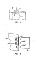
- a tip 10 of a turbine blade to be repaired is illustrated.
- the blade tip 10 has an area 12 to be repaired.
- the blade tip 10 has an open internal cooling cavity 14 in the area to be repaired.
- a piece 16 of backing material formed from a refractory metal material is positioned over the area to be repaired to prevent the entry of the repair material into the cavity 14.
- the refractory metal material preferably has a melting point in excess of 1455°C (2651°F) and most preferably a melting point in excess of 1650°C (3000°F).
- Suitable refractory metals for the backing material 16 include, niobium, tantalum, molybdenum, tungsten, metals having a melting point higher than the melting point of nickel, such as platinum, iridium, and the like, and their alloys.
- the refractory metal backing material 16 may be uncoated or coated. If heat input of the repair is high, a diffusion barrier coating can be applied to the refractory material.
- Candidates include, but are not limited to, oxide ceramics such as alumina or mullite. If an oxide ceramic coating is used, an intermediate coating layer such as a silicide may be used to help coating adherence. When coated with ceramic, it is preferred to nickel plate over the alumina or mullite to aid in wetting the repair filler metal.
- the coating system may also include a nickel aluminide layer left behind after repair to improve the oxidation resistance of the coating.
- the refractory metal backing material may just be nickel plated using electrolytic nickel on at least one side if heat input is low. As previously mentioned, the presence of the coating enhances the wettability of the backing material during the subsequent welding process.
- a repair filler metal material 20 is deposited over the backing material 16 and subjected to a welding operation.
- the repair filler metal material is deposited in an amount sufficient to fill the area 12 to be repaired.
- the repair filler metal material may comprise a cobalt based material, such as MERL 72, or a nickel based material, such as INCO 625.
- the repair filler metal may be a filler metal of the base alloy composition.
- the repair filler metal material may be applied using any suitable welding technique known in the art such as a TIG repair welding technique. During the welding step, the heat input may be kept low to prevent alloying.
- the refractory metal backing material 16 may be removed by an acid chemical treatment using a nitric acid-sulfuric acid solution.
- the solution may have 2 parts nitric acid and 1 part sulfuric acid added to 2 parts water.
- the mixture is preferably heated to a temperature up to 65°C (150°F) to increase the dissolution rate.
- the refractory metal backing material 16 may be removed using an oxidizing heat treatment in which air is flowed through the interior of the blade.
- the flowing air may be at a temperature in the range of 760°C (1400°F) to 900°C (1650°F) and may be flowed through the blade interior for a time in the range of from 1 to 4 hours.
- the oxidizing heat treatment may be performed either in a furnace or by direct resistant heating.
- the removal of the refractory metal backing material may be omitted if the alloying of the refractory metal with filler material is controlled.
- a method for repairing a trailing edge 30 of a turbine blade is illustrated.
- a piece 32 of refractory metal backing material is first cut to conform to the shape of the blade trailing edge and any internal cooling cavity therein.
- Any suitable cutting technique known in the art such as laser cutting, photo etching, stamping, or water jet cutting may be used to cut the refractory metal backing material.
- the refractory metal material may be one of the materials mentioned hereinabove and may be coated or uncoated as discussed above.
- the piece 32 of refractory metal backing material preferably in foil form, is placed over the area 34 to be repaired.
- a repair filler metal material is then deposited over the piece of refractory material 32 and subjected to a welding treatment to re-establish the blade trailing edge including its cooling features 36.
- the refractory metal backing material may be removed using either an acid chemical treatment, such as that described above, or an oxidizing heat treatment, such as that described above.
- the present invention is advantageous in that it allows a refractory metal material to act as a weld backing material to allow welding over open cavities or to re-establish internal cooling geometry.
- the refractory metal material can later be removed if desired without the need for extensive post welding blend processing or machining such as EDM machining. This method has particular utility in the repair of investment castings.
Landscapes
- Engineering & Computer Science (AREA)
- Mechanical Engineering (AREA)
- Physics & Mathematics (AREA)
- Optics & Photonics (AREA)
- Plasma & Fusion (AREA)
- General Engineering & Computer Science (AREA)
- Turbine Rotor Nozzle Sealing (AREA)
- Coating By Spraying Or Casting (AREA)
- Other Surface Treatments For Metallic Materials (AREA)
- Arc Welding In General (AREA)
Claims (32)
- Verfahren zum Ausbessern einer Komponente für eine Turbinenmaschine, folgende Schritte aufweisend:Platzieren eines Stücks aus hitzebeständigem Metallmaterial (16; 32) über einem auszubessernden Bereich (12; 34) der Komponente;Aufbringen eines Reparaturfüllmetallmaterials (20) über dem Stück aus hitzebeständigem Metallmaterial (16; 32) in einer Menge, die zum Füllen des auszubessernden Bereichs (12; 34) der Komponente ausreichend ist; undUnterziehen des Reparaturfüllmetallmaterials (20) einer Schweißbehandlung;wobei der auszubessernde Bereich (12; 34) einen offenen Hohlraum (14) oder eine Kühleinrichtung (36) hat, und der Schritt des Platzierens ein Anbringen des Stücks aus hitzebeständigem Metallmaterial (16; 32) dergestalt, dass es das Reparaturfüllmetallmaterial (20) daran hindert, in den offenen Hohlraum (14) oder in die Kühleinrichtung (36) einzutreten, aufweist.
- Verfahren nach Anspruch 1, bei dem der Schritt des Platzierens ein Platzieren eines Materialstücks (16; 32), das aus einem Material, das ausgewählt wird aus der Gruppe, die aus Niob, Tantal, Molybdän, Wolfram, einem Metall mit einem Schmelzpunkt, der höher ist als der Schmelzpunkt von Nickel, und Legierungen davon besteht, hergestellt ist, über dem auszubessernden Bereich (12; 34) aufweist.
- Verfahren nach Anspruch 1 oder 2, bei dem der Schritt des Platzierens ein Platzieren eines Stücks aus hitzebeständigem Metallmaterial (16; 32) mit einer Beschichtung über dem auszubessernden Bereich (12; 34) aufweist.
- Verfahren nach Anspruch 3, bei dem der Schritt des Platzierens ein Platzieren eines Stücks aus hitzebeständigem Metallmaterial (16; 32) mit einer Nickelplattierung auf mindestens einer Oberfläche über dem auszubessernden Bereich (12; 34) aufweist.
- Verfahren nach Anspruch 3, bei dem der Schritt des Platzierens ein Platzieren eines Stücks aus hitzebeständigem Metallmaterial (16; 32) mit einer Chrombeschichtung auf mindestens einer Oberfläche über dem auszubessernden Bereich (12; 34) aufweist.
- Verfahren nach Anspruch 3, bei dem der Schritt des Platzierens ein Platzieren eines Stücks aus hitzebeständigem Metallmaterial (16; 32) mit einer Diffusionsbarrierebeschichtung über dem auszubessernden Bereich (12; 34) aufweist.
- Verfahren nach Anspruch 6, bei dem der Schritt des Platzierens ein Platzieren eines Stücks aus hitzebeständigem Metallmaterial (16; 32) mit einer Beschichtung, die eine Aluminiumoxid- oder Mullitbeschichtung aufweist, über dem auszubessernden Bereich (12; 34) aufweist.
- Verfahren nach Anspruch 6, bei dem der Schritt des Platzierens ein Platzieren eines Stücks aus hitzebeständigem Metallmaterial (16; 32) mit einer Aluminiumoxid- oder Mullitbeschichtungsschicht und einer Silicid-Zwischenschicht über dem auszubessernden Bereich (12; 34) aufweist.
- Verfahren nach Anspruch 8, bei dem das hitzebeständige Metallmaterial (16; 32) außerdem eine Nickelplattierungs-Außenschicht hat.
- Verfahren nach irgendeinem vorangehenden Anspruch, bei dem der Schritt des Platzierens ein Platzieren eines Stücks aus hitzebeständigem Metallmaterial (16; 32) mit einem Schmelzpunkt über 1445°C über dem auszubessernden Bereich (12; 34) aufweist.
- Verfahren nach Anspruch 10, bei dem das hitzebeständige Metallmaterial (16; 32) einen Schmelzpunkt über 1650°C hat.
- Verfahren nach irgendeinem vorangehenden Anspruch, bei dem der offene Hohlraum einen offenen inneren Kühlhohlraum (14) aufweist, und der Schritt des Platzierens ein Anbringen des hitzebeständigen Metallmaterials (16) dergestalt, dass es das Reparaturfüllmetallmaterial (20) daran hindert, in den inneren Kühlhohlraum (14) einzutreten, aufweist.
- Verfahren nach irgendeinem der Ansprüche 1 bis 11, bei dem das hitzebeständige Metallmaterial (16) eine zugeschnittene Folie ist, die sich an die Form des offenen Hohlraums (14) in der Komponente anpasst.
- Verfahren nach irgendeinem vorangehenden Anspruch, außerdem aufweisend ein Entfernen des hitzebeständigen Metallmaterials (16; 32) nach der Vollendung des Schweißschritts unter Verwendung einer chemischen Säurebehandlung.
- Verfahren nach irgendeinem der Ansprüche 1 bis 13, außerdem aufweisend ein Entfernen des hitzebeständigen Metallmaterials (16; 32) nach der Vollendung des Schweißschritts unter Verwendung einer oxidierenden Wärmebehandlung.
- Verfahren nach irgendeinem vorangehenden Anspruch, bei dem der Schritt des Platzierens ein Platzieren des Stücks aus hitzebeständigem Metallmaterial (16; 32) über einem auszubessernden Bereich eines Investment-gegossenen Presskörpers aufweist.
- Verfahren nach Anspruch 1, bei dem die Komponente eine Turbinenlaufschaufel ist, und bei dem das Verfahren ein Ausbessern eines Endbereichs (10) der Laufschaufel aufweist, wobei der Endbereich einen offenen inneren Kühlhohlraum (14) in dem auszubessernden Bereich (12) hat.
- Verfahren nach Anspruch 17, bei dem der Schritt des Platzierens ein Anbringen eines Stücks aus hitzebeständigem Metallmaterial (16), das ausgewählt wird aus der Gruppe, die aus Niob, Tantal, Molybdän, Wolfram, einem Metall mit einem Schmelzpunkt, der höher als der Schmelzpunkt von Nickel ist, und Legierungen davon besteht, über dem auszubessernden Bereich (12) aufweist.
- Verfahren nach Anspruch 17 oder 18, bei dem der Schritt des Platzierens ein Anbringen eines Stücks aus hitzebeständigem Metallmaterial (16) mit einer Beschichtung über dem auszubessernden Bereich (12) aufweist.
- Verfahren nach Anspruch 19, bei dem der Schritt des Platzierens ein Anbringen eines Stücks aus hitzebeständigem Metallmaterial (16), das mit einem Nickel enthaltenden Material plattiert ist, über dem auszubessernden Bereich (12) aufweist.
- Verfahren nach Anspruch 19, bei dem der Schritt des Platzierens ein Anbringen eines Stücks aus hitzebeständigem Metallmaterial (16), das mit einem Chrom enthaltenden Material beschichtet ist, über dem auszubessernden Bereich (12) aufweist.
- Verfahren nach Anspruch 19, bei dem der Schritt des Platzierens ein Anbringen eines Stücks aus hitzebeständigem Metallmaterial (16) mit einer Oxidkeramik-Beschichtungsschicht, einer Zwischenschicht aus Silicid und einer ρlattierten Nickel-Außenschicht über dem auszubessernden Bereich (12) aufweist.
- Verfahren nach irgendeinem der Ansprüche 17 bis 22, außerdem aufweisend ein Entfernen des hitzebeständigen Metallmaterials (16) nach der Vollendung des Schweißschritts unter Verwendung einer chemischen Säurebehandlung.
- Verfahren nach irgendeinem der Ansprüche 17 bis 23, außerdem aufweisend ein Entfernen des hitzebeständigen Metallmaterials (16) nach der Vollendung des Schweißschritts unter Verwendung einer oxidierenden Wärmebehandlung.
- Verfahren nach Anspruch 1, bei dem die Komponente eine Turbinenlaufschaufel ist, und das Verfahren ein Ausbessern einer Hinterkante (30) der Laufschaufel aufweist durch:Zuschneiden einer Folie (32) aus hitzebeständigem Metallmaterial, so dass sie sich der Form der Hinterkante (30) und der Kühleinrichtung (36) anpasst; und wobei:der Schritt des Platzierens ein Anbringen der zugeschnittenen Folie (32) aus hitzebeständigem Metallmaterial über dem auszubessernden Bereich (34) der Hinterkante aufweist;der Schritt des Aufbringens ein Auftragen des Reparaturfüllmetallmaterials über der Folie (32) aus hitzebeständigem Metallmaterial aufweist.
- Verfahren nach Anspruch 25, bei dem der Schritt des Zuschneidens ein Zuschneiden eines Folienmaterials (32), das aus einem hitzebeständigen Metall, das ausgewählt wird aus der Gruppe, die aus Niob, Tantal, Molybdän, Wolfram, einem Metall mit einem Schmelzpunkt, der höher ist als der Schmelzpunkt von Nickel, und Legierungen davon besteht, hergestellt ist, aufweist.
- Verfahren nach Anspruch 25 oder 26, bei dem sich auf dem Folienmaterial (32) eine Beschichtung befindet.
- Verfahren nach Anspruch 27, bei dem sich auf dem Folienmaterial (32) eine Nickelplattierung befindet.
- Verfahren nach Anspruch 27, bei dem sich auf dem Folienmaterial (32) eine Chrombeschichtung befindet.
- Verfahren nach Anspruch 27, bei dem sich auf dem Folienmaterial (32) eine Nickel-plattierte Keramikbeschichtung befindet.
- Verfahren nach irgendeinem der Ansprüche 25 bis 30, außerdem aufweisend ein Entfernen des hitzebeständigen Metallfolienmaterials (32) nach Vollendung des Schweißschritts unter Verwendung einer chemischen Säurebehandlung.
- Verfahren nach irgendeinem der Ansprüche 25 bis 30, außerdem aufweisend ein Entfernen des hitzebeständigen Metallfolienmaterials (32) nach Vollendung des Schweißschritts unter Verwendung einer oxidierenden Wärmebehandlung.
Applications Claiming Priority (2)
| Application Number | Priority Date | Filing Date | Title |
|---|---|---|---|
| US10/167,679 US6742698B2 (en) | 2002-06-10 | 2002-06-10 | Refractory metal backing material for weld repair |
| US167679 | 2002-06-10 |
Publications (4)
| Publication Number | Publication Date |
|---|---|
| EP1371439A1 EP1371439A1 (de) | 2003-12-17 |
| EP1371439B1 EP1371439B1 (de) | 2008-08-27 |
| EP1371439B9 true EP1371439B9 (de) | 2011-05-25 |
| EP1371439B2 EP1371439B2 (de) | 2014-06-25 |
Family
ID=29583769
Family Applications (1)
| Application Number | Title | Priority Date | Filing Date |
|---|---|---|---|
| EP03253664.1A Expired - Lifetime EP1371439B2 (de) | 2002-06-10 | 2003-06-10 | Verfahren zum Schweissreparieren einer Komponente für einen Turbinenmotor mit einem refraktären metallischen Unterlagenmaterial |
Country Status (7)
| Country | Link |
|---|---|
| US (1) | US6742698B2 (de) |
| EP (1) | EP1371439B2 (de) |
| JP (1) | JP3825016B2 (de) |
| KR (1) | KR20030095330A (de) |
| AT (1) | ATE406230T1 (de) |
| DE (1) | DE60323181D1 (de) |
| SG (1) | SG107654A1 (de) |
Families Citing this family (39)
| Publication number | Priority date | Publication date | Assignee | Title |
|---|---|---|---|---|
| JP4229734B2 (ja) | 2003-03-20 | 2009-02-25 | 株式会社Ihi | 薄肉部分の肉盛溶接方法 |
| US7144220B2 (en) * | 2004-07-30 | 2006-12-05 | United Technologies Corporation | Investment casting |
| US7533795B2 (en) * | 2004-12-22 | 2009-05-19 | General Electric Company | Welding process |
| US7360678B2 (en) * | 2005-01-27 | 2008-04-22 | United Technologies Corporation | Repair and reclassification of superalloy components |
| JP2008533426A (ja) * | 2005-03-18 | 2008-08-21 | キャリア・コマーシャル・リフリージレーション・インコーポレーテッド | 遷臨界二酸化炭素冷蔵システムの凝縮水による熱伝達 |
| US7690111B2 (en) * | 2005-04-14 | 2010-04-06 | Mechanical Dynamics And Analysis, Llc | Method and apparatus for repairing turbine rotor |
| US20060248718A1 (en) * | 2005-05-06 | 2006-11-09 | United Technologies Corporation | Superalloy repair methods and inserts |
| US7966707B2 (en) * | 2005-05-06 | 2011-06-28 | United Technologies Corporation | Method for repairing superalloy components using inserts |
| US7367488B2 (en) * | 2005-05-10 | 2008-05-06 | Honeywell International, Inc. | Method of repair of thin wall housings |
| US20070044306A1 (en) | 2005-08-29 | 2007-03-01 | United Technologies Corporation | Superalloy repair methods |
| US9227278B2 (en) * | 2005-10-13 | 2016-01-05 | United Technologies Corporation | Bolt hole repair technique |
| US7552855B2 (en) * | 2005-10-13 | 2009-06-30 | United Technologies Corporation | Hole repair technique and apparatus |
| US7761989B2 (en) * | 2005-11-22 | 2010-07-27 | United Technologies Corporation | Methods for repairing gas turbine engine components |
| US20070158389A1 (en) * | 2006-01-06 | 2007-07-12 | United Technologies Corporation | Turbine element repair fixture |
| SG134184A1 (en) * | 2006-01-16 | 2007-08-29 | United Technologies Corp | Chordwidth restoration of a trailing edge of a turbine airfoil by laser clad |
| US20080017280A1 (en) * | 2006-07-18 | 2008-01-24 | United Technologies Corporation | Process for repairing turbine engine components |
| ATE457412T1 (de) * | 2006-10-20 | 2010-02-15 | Siemens Ag | Verfahren zur reparatur einer turbinenschaufel |
| US20080265005A1 (en) * | 2007-04-30 | 2008-10-30 | United Technologies Corporation | Brazing process incorporating graphitic preforms |
| US8360734B2 (en) * | 2007-12-13 | 2013-01-29 | United Technologies Corporation | Method for repairing an airfoil |
| EP2078578A1 (de) * | 2008-01-10 | 2009-07-15 | Siemens Aktiengesellschaft | Belotung von Löchern, Verfahren zum Beschichten und Lotgutstäbchen |
| US8925200B2 (en) * | 2008-03-27 | 2015-01-06 | United Technologies Corporation | Method for repairing an airfoil |
| US8367964B2 (en) * | 2008-08-06 | 2013-02-05 | United Technologies Corp. | Repair methods involving conductive heat resistance welding |
| US9321116B2 (en) * | 2009-03-05 | 2016-04-26 | United Technologies Corporation | Cold metal transfer gas metal arc welding apparatus and method of operation |
| RU2419527C1 (ru) * | 2009-10-29 | 2011-05-27 | Российская Федерация, от имени которой выступает Министерство промышленности и торговли (Минпромторг России) | Способ ремонта моноколеса турбомашин |
| DE102010005863B4 (de) * | 2010-01-26 | 2017-02-16 | Lufthansa Technik Ag | Verfahren zum Strahlschweißen eines Objekts und entsprechendes Strahlenfangmittel |
| US20140271974A1 (en) * | 2013-03-14 | 2014-09-18 | Honda Motor Co., Ltd. | Conforming cooling method and mold |
| US20190118442A9 (en) * | 2010-04-20 | 2019-04-25 | Honda Motor Co., Ltd. | Conforming cooling method and mold |
| EP2453030A1 (de) * | 2010-11-08 | 2012-05-16 | United Technologies Corporation | Verfahren zum Reparieren/Neuausstatten/Erzeugen eines Turbinenmotorbauteils |
| US9303517B2 (en) * | 2012-06-15 | 2016-04-05 | General Electric Company | Channel marker and related methods |
| US10563533B2 (en) | 2013-09-13 | 2020-02-18 | United Technologies Corporation | Repair or remanufacture of blade outer air seals for a gas turbine engine |
| JP6235708B2 (ja) * | 2013-10-30 | 2017-11-22 | ユナイテッド テクノロジーズ コーポレイションUnited Technologies Corporation | ガスタービンエンジン非融接性ニッケル鋳造物のためのレーザ粉末溶着による溶接補修 |
| EP2881205A1 (de) * | 2013-12-04 | 2015-06-10 | Alstom Technology Ltd | Verfahren zur Herstellung einer Hartlötfuge und Verfahren zum Hartlöten oder Löten |
| US20150165569A1 (en) * | 2013-12-18 | 2015-06-18 | Petya M. Georgieva | Repair of turbine engine components using waterjet ablation process |
| US10006293B1 (en) * | 2015-07-22 | 2018-06-26 | Florida Turbine Technologies, Inc. | Apparatus and process for refining features in an additive manufactured part |
| CN105290559B (zh) * | 2015-11-12 | 2017-10-03 | 西安航空动力股份有限公司 | 一种静子叶片扇形块焊接组件储能点焊定位夹紧装置 |
| US10815782B2 (en) * | 2016-06-24 | 2020-10-27 | General Electric Company | Methods for repairing airfoil trailing edges to include ejection slots therein |
| RU2751784C2 (ru) * | 2018-06-13 | 2021-07-16 | Общество с ограниченной ответственностью "ТермоЛазер" | Способ лазерной обработки поверхности стальных лопаток турбин энергетических установок |
| US11541470B2 (en) | 2021-04-02 | 2023-01-03 | General Electric Company | Methods of furnace-less brazing |
| RU2768906C1 (ru) * | 2021-07-02 | 2022-03-25 | Федеральное государственное бюджетное образовательное учреждение высшего образования «Московский авиационный институт (национальный исследовательский университет)» | Способ восстановления лопаток компрессора газотурбинного двигателя |
Family Cites Families (34)
| Publication number | Priority date | Publication date | Assignee | Title |
|---|---|---|---|---|
| US3531848A (en) † | 1966-01-10 | 1970-10-06 | Battelle Development Corp | Fabrication of integral structures |
| US3576065A (en) † | 1969-03-24 | 1971-04-27 | Chromalloy American Corp | Repair of apertured machine components |
| US3957104A (en) * | 1974-02-27 | 1976-05-18 | The United States Of America As Represented By The Administrator Of The United States National Aeronautics And Space Administration | Method of making an apertured casting |
| US4110887A (en) * | 1977-04-25 | 1978-09-05 | United States Steel Corporation | Method of repairing slag and cinder pots and other heavy steel articles |
| JPS5542129A (en) † | 1978-09-20 | 1980-03-25 | Hitachi Ltd | Nozzle vane repair method of turbine diaphragm |
| JPS56167802A (en) † | 1980-05-28 | 1981-12-23 | Toshiba Corp | Repairing method of nozzle blade for steam turbine |
| US4574451A (en) † | 1982-12-22 | 1986-03-11 | General Electric Company | Method for producing an article with a fluid passage |
| US4705203A (en) * | 1986-08-04 | 1987-11-10 | United Technologies Corporation | Repair of surface defects in superalloy articles |
| US4726104A (en) † | 1986-11-20 | 1988-02-23 | United Technologies Corporation | Methods for weld repairing hollow, air cooled turbine blades and vanes |
| JPS63295802A (ja) † | 1987-05-28 | 1988-12-02 | Toshiba Corp | 蒸気タ−ビンのノズル板補修方法 |
| US4775602A (en) * | 1987-07-06 | 1988-10-04 | General Electric Company | Metallic coating of improved life |
| US5175411A (en) * | 1991-08-23 | 1992-12-29 | Westinghouse Electric Corp. | Method for welding structural gaps |
| DE4327189C2 (de) * | 1993-08-13 | 1996-02-01 | Mtu Muenchen Gmbh | Reparaturverfahren für im Kopf- oder Kantenbereich beschädigte Schaufelblätter von Turbomaschinen |
| US5511721A (en) † | 1994-11-07 | 1996-04-30 | General Electric Company | Braze blocking insert for liquid phase brazing operations |
| US5553370A (en) * | 1995-02-09 | 1996-09-10 | Pepe; John | Method for repair of steam turbine blades |
| US5666643A (en) * | 1995-02-23 | 1997-09-09 | General Electric Company | High temperature braze material |
| FR2742368B1 (fr) * | 1995-12-18 | 1998-03-06 | Framatome Sa | Procede de raccordement par soudage heterogene bout a bout de deux pieces de natures differentes et utilisations |
| DE19547903C1 (de) * | 1995-12-21 | 1997-03-20 | Mtu Muenchen Gmbh | Verfahren zur Herstellung oder Instandsetzung von Schaufeln für Turbomaschinen mittels Laserstrahlauftragsschweißen unter Verwendung eines Metallpulvers als Zusatzwerkstoff, sowie Stützform zur Herstellung oder Instandsetzung derartiger Schaufeln und Verfahren zur Herstellung der Stützform |
| US5806751A (en) * | 1996-10-17 | 1998-09-15 | United Technologies Corporation | Method of repairing metallic alloy articles, such as gas turbine engine components |
| EP0924020B1 (de) * | 1997-12-19 | 2008-02-06 | United Technologies Corporation | Verfahren und Vorrichtung zum Auftragen von Materialen auf einer Strömungsleiteinrichtung eines Gasturbinentriebwerkes |
| US6519291B1 (en) † | 1998-02-03 | 2003-02-11 | Lucent Technologies Inc. | Reduction of interference in discrete multi-tone (DMT) based communications systems |
| DE19834238A1 (de) * | 1998-07-29 | 2000-02-10 | Juergen Roeders | Metallisches Bauteil mit zumindest einer innenliegenden, rohrförmigen oder kanalförmigen Ausnehmung sowie Verfahren zu dessen Herstellung |
| US6200689B1 (en) † | 1998-10-14 | 2001-03-13 | General Electric Company | Laser shock peened gas turbine engine seal teeth |
| US6283356B1 (en) * | 1999-05-28 | 2001-09-04 | General Electric Company | Repair of a recess in an article surface |
| DE59909337D1 (de) * | 1999-06-03 | 2004-06-03 | Alstom Technology Ltd Baden | Verfahren zur Herstellung oder zur Reparatur von Kühlkanälen in einstristallinen Komponenten von Gasturbinen |
| US6199746B1 (en) † | 1999-08-02 | 2001-03-13 | General Electric Company | Method for preparing superalloy castings using a metallurgically bonded tapered plug |
| DE19963010B4 (de) † | 1999-12-22 | 2005-02-24 | Fraunhofer-Gesellschaft zur Förderung der angewandten Forschung e.V. | Verfahren und Vorrichtung zur Laserbearbeitung von Werkstücken |
| US6332272B1 (en) * | 2000-01-07 | 2001-12-25 | Siemens Westinghouse Power Corporation | Method of repairing a turbine blade |
| DE10008257A1 (de) * | 2000-02-23 | 2001-08-30 | Alstom Power Schweiz Ag Baden | Verfahren zur Reparatur einer Gasturbinenkomponente |
| US6413578B1 (en) * | 2000-10-12 | 2002-07-02 | General Electric Company | Method for repairing a thermal barrier coating and repaired coating formed thereby |
| DE10065406A1 (de) * | 2000-12-27 | 2002-07-04 | Alstom Switzerland Ltd | Verfahren zum Reparieren von Schadstellen an einem Metallbauteil |
| US6884959B2 (en) * | 2001-09-07 | 2005-04-26 | Electric Power Research Institute, Inc. | Controlled composition welding method |
| US6838190B2 (en) * | 2001-12-20 | 2005-01-04 | General Electric Company | Article with intermediate layer and protective layer, and its fabrication |
| JP2004084604A (ja) † | 2002-08-28 | 2004-03-18 | Mitsubishi Heavy Ind Ltd | タービン動翼のプラットホーム補修方法、及び、タービン動翼 |
-
2002
- 2002-06-10 US US10/167,679 patent/US6742698B2/en not_active Expired - Lifetime
-
2003
- 2003-05-23 SG SG200302765A patent/SG107654A1/en unknown
- 2003-06-09 KR KR10-2003-0036906A patent/KR20030095330A/ko not_active Ceased
- 2003-06-10 DE DE60323181T patent/DE60323181D1/de not_active Expired - Lifetime
- 2003-06-10 JP JP2003165019A patent/JP3825016B2/ja not_active Expired - Fee Related
- 2003-06-10 EP EP03253664.1A patent/EP1371439B2/de not_active Expired - Lifetime
- 2003-06-10 AT AT03253664T patent/ATE406230T1/de not_active IP Right Cessation
Also Published As
| Publication number | Publication date |
|---|---|
| US20030226878A1 (en) | 2003-12-11 |
| JP2004074395A (ja) | 2004-03-11 |
| EP1371439A1 (de) | 2003-12-17 |
| EP1371439B1 (de) | 2008-08-27 |
| EP1371439B2 (de) | 2014-06-25 |
| KR20030095330A (ko) | 2003-12-18 |
| JP3825016B2 (ja) | 2006-09-20 |
| ATE406230T1 (de) | 2008-09-15 |
| DE60323181D1 (de) | 2008-10-09 |
| US6742698B2 (en) | 2004-06-01 |
| SG107654A1 (en) | 2004-12-29 |
Similar Documents
| Publication | Publication Date | Title |
|---|---|---|
| EP1371439B9 (de) | Verfahren zum Schweissreparieren einer Komponente für einen Turbinenmotor mit einem refraktären metallischen Unterlagenmaterial | |
| EP1880787A1 (de) | Verfahren zur Reparatur von Turbinenmotorkomponenten | |
| EP1721697B1 (de) | Reparaturverfahren für Superlegierungen und Inserts | |
| EP1759799B1 (de) | Verfahren zur Formgebung oder Herstellung von Turbinenmotorelementen | |
| JP4375930B2 (ja) | タービンエンジン羽根の台板のレーザークラッディング | |
| US8726501B2 (en) | Method of welding single crystal turbine blade tips with an oxidation-resistant filler material | |
| US5813118A (en) | Method for repairing an air cooled turbine engine airfoil | |
| EP1775054B1 (de) | Verfahren zum Verschliessen einer Gusskernöffnung in einer hohlen Turbinenschaufel aus einer nickelbasierten Superlegierung | |
| JP2897803B2 (ja) | 超合金製部品に被覆を形成する方法 | |
| EP3345718B1 (de) | Lötreparatur einer struktur von schwer zu scheissenden superlegierungskomponenten mittels diffusionslegierungseinsatz | |
| US7093335B2 (en) | Coated article and method for repairing a coated surface | |
| EP1721696A1 (de) | Reparaturverfahren für Superlegierungen und Inserts | |
| US5304039A (en) | Method for providing an extension on an end of an article and extended article | |
| JP2003507614A (ja) | タービン羽根のエアフォイルを交換する方法 | |
| EP1788196B1 (de) | Reparaturverfahren eines Bauteils einer Gasturbine | |
| US5778960A (en) | Method for providing an extension on an end of an article |
Legal Events
| Date | Code | Title | Description |
|---|---|---|---|
| PUAI | Public reference made under article 153(3) epc to a published international application that has entered the european phase |
Free format text: ORIGINAL CODE: 0009012 |
|
| AK | Designated contracting states |
Kind code of ref document: A1 Designated state(s): AT BE BG CH CY CZ DE DK EE ES FI FR GB GR HU IE IT LI LU MC NL PT RO SE SI SK TR |
|
| AX | Request for extension of the european patent |
Extension state: AL LT LV MK |
|
| 17P | Request for examination filed |
Effective date: 20040518 |
|
| AKX | Designation fees paid |
Designated state(s): AT BE BG CH CY CZ DE DK EE ES FI FR GB GR HU IE IT LI LU MC NL PT RO SE SI SK TR |
|
| 17Q | First examination report despatched |
Effective date: 20041015 |
|
| 17Q | First examination report despatched |
Effective date: 20041015 |
|
| GRAP | Despatch of communication of intention to grant a patent |
Free format text: ORIGINAL CODE: EPIDOSNIGR1 |
|
| RTI1 | Title (correction) |
Free format text: METHOD OF WELD REPAIRING A COMPONENT FOR A TURBINE ENGINE WITH A REFRACTORY METAL BACKING MATERIAL |
|
| GRAS | Grant fee paid |
Free format text: ORIGINAL CODE: EPIDOSNIGR3 |
|
| GRAA | (expected) grant |
Free format text: ORIGINAL CODE: 0009210 |
|
| GRAL | Information related to payment of fee for publishing/printing deleted |
Free format text: ORIGINAL CODE: EPIDOSDIGR3 |
|
| GRAS | Grant fee paid |
Free format text: ORIGINAL CODE: EPIDOSNIGR3 |
|
| GRAL | Information related to payment of fee for publishing/printing deleted |
Free format text: ORIGINAL CODE: EPIDOSDIGR3 |
|
| GRAS | Grant fee paid |
Free format text: ORIGINAL CODE: EPIDOSNIGR3 |
|
| AK | Designated contracting states |
Kind code of ref document: B1 Designated state(s): AT BE BG CH CY CZ DE DK EE ES FI FR GB GR HU IE IT LI LU MC NL PT RO SE SI SK TR |
|
| REG | Reference to a national code |
Ref country code: GB Ref legal event code: FG4D |
|
| REG | Reference to a national code |
Ref country code: CH Ref legal event code: EP |
|
| REG | Reference to a national code |
Ref country code: IE Ref legal event code: FG4D |
|
| REF | Corresponds to: |
Ref document number: 60323181 Country of ref document: DE Date of ref document: 20081009 Kind code of ref document: P |
|
| PG25 | Lapsed in a contracting state [announced via postgrant information from national office to epo] |
Ref country code: NL Free format text: LAPSE BECAUSE OF FAILURE TO SUBMIT A TRANSLATION OF THE DESCRIPTION OR TO PAY THE FEE WITHIN THE PRESCRIBED TIME-LIMIT Effective date: 20080827 Ref country code: ES Free format text: LAPSE BECAUSE OF FAILURE TO SUBMIT A TRANSLATION OF THE DESCRIPTION OR TO PAY THE FEE WITHIN THE PRESCRIBED TIME-LIMIT Effective date: 20081208 |
|
| PG25 | Lapsed in a contracting state [announced via postgrant information from national office to epo] |
Ref country code: SI Free format text: LAPSE BECAUSE OF FAILURE TO SUBMIT A TRANSLATION OF THE DESCRIPTION OR TO PAY THE FEE WITHIN THE PRESCRIBED TIME-LIMIT Effective date: 20080827 Ref country code: FI Free format text: LAPSE BECAUSE OF FAILURE TO SUBMIT A TRANSLATION OF THE DESCRIPTION OR TO PAY THE FEE WITHIN THE PRESCRIBED TIME-LIMIT Effective date: 20080827 Ref country code: AT Free format text: LAPSE BECAUSE OF FAILURE TO SUBMIT A TRANSLATION OF THE DESCRIPTION OR TO PAY THE FEE WITHIN THE PRESCRIBED TIME-LIMIT Effective date: 20080827 |
|
| PG25 | Lapsed in a contracting state [announced via postgrant information from national office to epo] |
Ref country code: BE Free format text: LAPSE BECAUSE OF FAILURE TO SUBMIT A TRANSLATION OF THE DESCRIPTION OR TO PAY THE FEE WITHIN THE PRESCRIBED TIME-LIMIT Effective date: 20080827 |
|
| PLBI | Opposition filed |
Free format text: ORIGINAL CODE: 0009260 |
|
| PG25 | Lapsed in a contracting state [announced via postgrant information from national office to epo] |
Ref country code: DK Free format text: LAPSE BECAUSE OF FAILURE TO SUBMIT A TRANSLATION OF THE DESCRIPTION OR TO PAY THE FEE WITHIN THE PRESCRIBED TIME-LIMIT Effective date: 20080827 Ref country code: BG Free format text: LAPSE BECAUSE OF FAILURE TO SUBMIT A TRANSLATION OF THE DESCRIPTION OR TO PAY THE FEE WITHIN THE PRESCRIBED TIME-LIMIT Effective date: 20081127 |
|
| 26 | Opposition filed |
Opponent name: SIEMENS AG Effective date: 20090409 |
|
| PG25 | Lapsed in a contracting state [announced via postgrant information from national office to epo] |
Ref country code: CZ Free format text: LAPSE BECAUSE OF FAILURE TO SUBMIT A TRANSLATION OF THE DESCRIPTION OR TO PAY THE FEE WITHIN THE PRESCRIBED TIME-LIMIT Effective date: 20080827 Ref country code: SK Free format text: LAPSE BECAUSE OF FAILURE TO SUBMIT A TRANSLATION OF THE DESCRIPTION OR TO PAY THE FEE WITHIN THE PRESCRIBED TIME-LIMIT Effective date: 20080827 Ref country code: RO Free format text: LAPSE BECAUSE OF FAILURE TO SUBMIT A TRANSLATION OF THE DESCRIPTION OR TO PAY THE FEE WITHIN THE PRESCRIBED TIME-LIMIT Effective date: 20080827 Ref country code: PT Free format text: LAPSE BECAUSE OF FAILURE TO SUBMIT A TRANSLATION OF THE DESCRIPTION OR TO PAY THE FEE WITHIN THE PRESCRIBED TIME-LIMIT Effective date: 20090127 |
|
| PLAX | Notice of opposition and request to file observation + time limit sent |
Free format text: ORIGINAL CODE: EPIDOSNOBS2 |
|
| PG25 | Lapsed in a contracting state [announced via postgrant information from national office to epo] |
Ref country code: EE Free format text: LAPSE BECAUSE OF FAILURE TO SUBMIT A TRANSLATION OF THE DESCRIPTION OR TO PAY THE FEE WITHIN THE PRESCRIBED TIME-LIMIT Effective date: 20080827 |
|
| PG25 | Lapsed in a contracting state [announced via postgrant information from national office to epo] |
Ref country code: IT Free format text: LAPSE BECAUSE OF FAILURE TO SUBMIT A TRANSLATION OF THE DESCRIPTION OR TO PAY THE FEE WITHIN THE PRESCRIBED TIME-LIMIT Effective date: 20080827 |
|
| PLAF | Information modified related to communication of a notice of opposition and request to file observations + time limit |
Free format text: ORIGINAL CODE: EPIDOSCOBS2 |
|
| PLBB | Reply of patent proprietor to notice(s) of opposition received |
Free format text: ORIGINAL CODE: EPIDOSNOBS3 |
|
| PG25 | Lapsed in a contracting state [announced via postgrant information from national office to epo] |
Ref country code: MC Free format text: LAPSE BECAUSE OF NON-PAYMENT OF DUE FEES Effective date: 20090630 Ref country code: SE Free format text: LAPSE BECAUSE OF FAILURE TO SUBMIT A TRANSLATION OF THE DESCRIPTION OR TO PAY THE FEE WITHIN THE PRESCRIBED TIME-LIMIT Effective date: 20081127 |
|
| REG | Reference to a national code |
Ref country code: CH Ref legal event code: PL |
|
| REG | Reference to a national code |
Ref country code: FR Ref legal event code: ST Effective date: 20100226 |
|
| REG | Reference to a national code |
Ref country code: IE Ref legal event code: MM4A |
|
| PG25 | Lapsed in a contracting state [announced via postgrant information from national office to epo] |
Ref country code: CH Free format text: LAPSE BECAUSE OF NON-PAYMENT OF DUE FEES Effective date: 20090630 Ref country code: LI Free format text: LAPSE BECAUSE OF NON-PAYMENT OF DUE FEES Effective date: 20090630 Ref country code: IE Free format text: LAPSE BECAUSE OF NON-PAYMENT OF DUE FEES Effective date: 20090610 Ref country code: FR Free format text: LAPSE BECAUSE OF NON-PAYMENT OF DUE FEES Effective date: 20090630 |
|
| PG25 | Lapsed in a contracting state [announced via postgrant information from national office to epo] |
Ref country code: GR Free format text: LAPSE BECAUSE OF FAILURE TO SUBMIT A TRANSLATION OF THE DESCRIPTION OR TO PAY THE FEE WITHIN THE PRESCRIBED TIME-LIMIT Effective date: 20081128 |
|
| PG25 | Lapsed in a contracting state [announced via postgrant information from national office to epo] |
Ref country code: LU Free format text: LAPSE BECAUSE OF NON-PAYMENT OF DUE FEES Effective date: 20090610 |
|
| PG25 | Lapsed in a contracting state [announced via postgrant information from national office to epo] |
Ref country code: HU Free format text: LAPSE BECAUSE OF FAILURE TO SUBMIT A TRANSLATION OF THE DESCRIPTION OR TO PAY THE FEE WITHIN THE PRESCRIBED TIME-LIMIT Effective date: 20090228 |
|
| PG25 | Lapsed in a contracting state [announced via postgrant information from national office to epo] |
Ref country code: TR Free format text: LAPSE BECAUSE OF FAILURE TO SUBMIT A TRANSLATION OF THE DESCRIPTION OR TO PAY THE FEE WITHIN THE PRESCRIBED TIME-LIMIT Effective date: 20080827 |
|
| PG25 | Lapsed in a contracting state [announced via postgrant information from national office to epo] |
Ref country code: CY Free format text: LAPSE BECAUSE OF FAILURE TO SUBMIT A TRANSLATION OF THE DESCRIPTION OR TO PAY THE FEE WITHIN THE PRESCRIBED TIME-LIMIT Effective date: 20080827 |
|
| PLAB | Opposition data, opponent's data or that of the opponent's representative modified |
Free format text: ORIGINAL CODE: 0009299OPPO |
|
| R26 | Opposition filed (corrected) |
Opponent name: SIEMENS AKTIENGESELLSCHAFT Effective date: 20090409 |
|
| PUAH | Patent maintained in amended form |
Free format text: ORIGINAL CODE: 0009272 |
|
| STAA | Information on the status of an ep patent application or granted ep patent |
Free format text: STATUS: PATENT MAINTAINED AS AMENDED |
|
| 27A | Patent maintained in amended form |
Effective date: 20140625 |
|
| AK | Designated contracting states |
Kind code of ref document: B2 Designated state(s): AT BE BG CH CY CZ DE DK EE ES FI FR GB GR HU IE IT LI LU MC NL PT RO SE SI SK TR |
|
| REG | Reference to a national code |
Ref country code: DE Ref legal event code: R102 Ref document number: 60323181 Country of ref document: DE |
|
| REG | Reference to a national code |
Ref country code: DE Ref legal event code: R102 Ref document number: 60323181 Country of ref document: DE Effective date: 20140625 |
|
| REG | Reference to a national code |
Ref country code: DE Ref legal event code: R082 Ref document number: 60323181 Country of ref document: DE Representative=s name: SCHMITT-NILSON SCHRAUD WAIBEL WOHLFROM PATENTA, DE |
|
| REG | Reference to a national code |
Ref country code: DE Ref legal event code: R082 Ref document number: 60323181 Country of ref document: DE Representative=s name: SCHMITT-NILSON SCHRAUD WAIBEL WOHLFROM PATENTA, DE Ref country code: DE Ref legal event code: R081 Ref document number: 60323181 Country of ref document: DE Owner name: UNITED TECHNOLOGIES CORP. (N.D.GES.D. STAATES , US Free format text: FORMER OWNER: UNITED TECHNOLOGIES CORPORATION, EAST HARTFORD, CONN., US |
|
| PGFP | Annual fee paid to national office [announced via postgrant information from national office to epo] |
Ref country code: DE Payment date: 20190521 Year of fee payment: 17 |
|
| PGFP | Annual fee paid to national office [announced via postgrant information from national office to epo] |
Ref country code: GB Payment date: 20190522 Year of fee payment: 17 |
|
| REG | Reference to a national code |
Ref country code: DE Ref legal event code: R119 Ref document number: 60323181 Country of ref document: DE |
|
| GBPC | Gb: european patent ceased through non-payment of renewal fee |
Effective date: 20200610 |
|
| PG25 | Lapsed in a contracting state [announced via postgrant information from national office to epo] |
Ref country code: GB Free format text: LAPSE BECAUSE OF NON-PAYMENT OF DUE FEES Effective date: 20200610 |
|
| PG25 | Lapsed in a contracting state [announced via postgrant information from national office to epo] |
Ref country code: DE Free format text: LAPSE BECAUSE OF NON-PAYMENT OF DUE FEES Effective date: 20210101 |