EP1370935B1 - Verfahren und vorrichtung zur graphischen geräteverwaltung mit einer virtuellen konsole - Google Patents
Verfahren und vorrichtung zur graphischen geräteverwaltung mit einer virtuellen konsole Download PDFInfo
- Publication number
- EP1370935B1 EP1370935B1 EP01948405A EP01948405A EP1370935B1 EP 1370935 B1 EP1370935 B1 EP 1370935B1 EP 01948405 A EP01948405 A EP 01948405A EP 01948405 A EP01948405 A EP 01948405A EP 1370935 B1 EP1370935 B1 EP 1370935B1
- Authority
- EP
- European Patent Office
- Prior art keywords
- cui
- gui
- configuration
- code
- graphical
- Prior art date
- Legal status (The legal status is an assumption and is not a legal conclusion. Google has not performed a legal analysis and makes no representation as to the accuracy of the status listed.)
- Expired - Lifetime
Links
Images




Classifications
-
- G—PHYSICS
- G06—COMPUTING OR CALCULATING; COUNTING
- G06F—ELECTRIC DIGITAL DATA PROCESSING
- G06F8/00—Arrangements for software engineering
- G06F8/30—Creation or generation of source code
- G06F8/38—Creation or generation of source code for implementing user interfaces
Definitions
- the present invention relates generally to software for developing graphical device management applications for managing remote devices. More specifically, the present invention relates to technology that enables the rapid development of graphical user interfaces for remote devices through the use of a virtual console.
- WO 96/14618 discloses control of non-computer system devices using a device interface to operate the device controls by manipulating a graphical representation of a computer connected to the device interface, using a visual network operating system based on object-oriented programming.
- the present generation of many networking and computing devices supports both local and remote methods of configuration.
- a locally connected terminal to configure a device using a console user interface (CUI) to the device's serial console is very common.
- a remotely connected workstation with a graphical user interface (GUI) to configure the same device is also an expected device management product feature.
- CUI console user interface
- GUI graphical user interface
- both the CUI and GUI must use the same predefined command set to update the configuration file.
- the ultimate purpose is to refresh the state of the remote device's configuration kernal (CK) by means of a configuration file.
- the CK includes all the variables, data structures and functions whose purpose is to maintain the state of the configuration of the device (e.g. user names, passwords, timeout values, etc.).
- the configuration file is an ASCII flat file that contains configuration commands used to refresh the CK.
- the brute force approach such as that used by previous versions of the Shiva Virtual Private Networking (VPN) Manager, one component of a suite of graphical network management applications from Intel Corporation, the assignee of the present invention, is illustrated in Figure 1 .
- the configuration file is downloaded from the remote device 110 into the GUI application.
- the user modifies the configuration file using the GUI application 120.
- the process is reversed by uploading the modified configuration file back to the remote device 130.
- the modified configuration file then refreshes the state of the CK with configuration changes that reflect the user modifications.
- GDMVC virtual console
- FIG. 2 wherein an block diagram illustrating the relationship of the GUI, CUI, and CK of the GDMVC method and apparatus in accordance with one embodiment is shown.
- the GUI 210 and CUI 220 form a self-contained application, with the CUI 220 running under the GUI 210.
- the CUI 220 is not running on an actual remote device, as in the prior art device management systems, it is referred to as a virtual console, hence the name of the present invention.
- the use of a virtual console avoids the difficulties inherent in attempting to interact directly with the remote device's CUI, such as latency problems (i.e. delays in refreshing the contents of the CK), and resource contention (i.e. when more than one user attempts to update the configuration at the same time, thereby creating a potential lockout situation).
- the method and apparatus of the present invention re-uses the CUI firmware code and underlying CK.
- the re-used CUI code is linked with the GUI code as a library.
- the interaction between the GUI 210 and the "virtual" CUI 220 i.e. the CUI running the re-used CUI code and underlying CK) is performed in a standardized manner.
- the standardization of the interaction is implemented through the use of a set of object-oriented classes and macros.
- a file containing all of the console commands that define the device's configuration is downloaded and passed to the CUI 220 running under the GUI 210, thereby initializing the state of the CK 230.
- the user can then use the facilities of the GUI 210 to make modifications to the device configuration, during which the GUI 210 invokes the facilities of the re-used CUI code and the underlying CK 230.
- the device's configuration is uploaded back to the remote device to refresh the state of the remote device's CK 230.
- GUI 210 as encapsulating the CUI 220 as a virtual console
- coding necessary to associate configuration commands with the GUI's graphical components is substantially reduced and does not require detailed intelligence about the configuration command set's behavior.
- a typical GUI application might employ a combination of tree views, list views and various dialogs to represent a configuration device.
- a command in the configuration file might be:
- the use of the macro provides one example of a tool for interacting between the GUI 210 and CUI 220 in a standardized manner. Implicit in the macro usage is that the configuration commands used by the remote CUI are already in a standard format, typically a keyword followed by one or more parameters.
- the CUI 220 updates the CK 230 and reconstructs the configuration file from the state of the CK 230. If the command sent by the GUI 210 to the CUI 220 is invalid, an error message is sent back to the GUI 210 for display to the user.
- the interaction between the GUI 210 and CUI 220 is implemented in the CUI 220 with a function having an interface similar to that of the following C prototype:
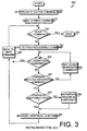
- FIG. 3 wherein a block diagram illustrating the standardized manner of refreshing the GUI 210 to reflect the state of the CK 230 as communicated by the CUI 220 is shown in accordance with one embodiment of the present invention.
- the standardized manner of refreshing the GUI 210 is employed whether the GUI 210 is being initialized following a download of a device's configuration, or whether the GUI 210 is being refreshed after the user has caused changes in the CK 230.
- the process involves interrogation 310 of the CUI 220 for a list of all of the device's configuration commands (i.e.
- the latter two steps are accomplished by looping through the command list one at a time until the end of the list is reached. Specifically, the process involves seeking to the first command in the list 315, and if the end of the list has not yet been reached 320, then seeking again to the first registered command 330. Once a matching registered command is found 345 the associated graphical component is identified 355. If an instance of the associated graphical component does not yet exist, then one is first instantiated 360 and then initialized 365. Otherwise, the existing instance of the associated graphical component is simply initialized 365. This process is repeated by seeking to the next command in the list 340 until the list is exhausted 325.
- an alternative method of comparing the list of commands to the command register is performed using a randomly accessible data repository for the comprehensive command register and associated graphical component and using a direct lookup by a command identifier, thereby eliminating the need for the looping logic.
- the interrogation 310 is accomplished by sending a command to the CUI 220.
- the command could be show config This command is passed in the 1 pszCmd parameter to the SendCommand call prototype previously described.
- the CUI 220 returns the list of commands in the lpszMsg parameter.
- Initialization 365 of a graphical component for a command also involves interaction in a standardized manner between the GUI 210 and the CUI 220.
- the interaction employs a common mechanism used by the CUI 220 to supply help text for a given command in the command set, i.e. passing the command to the CUI 220 followed by the "?” symbol.
- the initialization code then parses this information and sets the edit control to accept a maximum of 8 characters.
- FIG. 4 a block diagram illustrating the standardized manner of sending messages to the CUI 220 to update the CK 230 in response to user actions in the GUI 210 is shown in accordance with one embodiment of the present invention.
- the standardized manner of updating the CK 230 is invoked when the user completes a modification of a given graphical component. This typically occurs when the user has finished typing in the new value in the graphical component (e.g. the edit control) which then loses the input focus (i.e. when the user selects another control from the display or leaves the dialog).
- the first step in the process is to send 410 the configuration command associated with the graphical component to the CUI 220.
- this is accomplished by sending the command string representing the command to the CUI 220 using the C prototype SendCommand and the 1 pszCmd pointer.
- the CUI 220 replies with an error message, the text of that message is returned 420 to the GUI 210 using the 1 pszMSG pointer of SendCommand.
- the GUI 210 displays the error message to the user 430 and any graphical component-specific recovery from the error is performed 440. For example, in the case of a configuration command associated with an edit control graphical component, the GUI 210 sets the input focus back to that edit control so that the user can correct the error.
- the CUI 220 next determines whether the configuration command sent by the GUI 210 is interdependent with any other configuration commands 450. If so, the GUI 210 is refreshed using the standardized manner of refreshing the GUI 300 described in Figure 3 to reflect any changes in the CK 230 that may have resulted from the interdependencies.
- This virtual console approach can be used in the development of remote management tools for any computer or networking device that has a console interface, and whose CUI and CK code can be extracted for re-use. Even for devices without a console interface, the virtual console approach might still be feasible if a CUI could be created to encapsulate the existing CK code.
- Additional advantages to the virtual console approach to graphical device management includes the enforcement of consistency in the use of the remote device's command set, and the promotion of a normalized format for console help text.
- the close correspondence of the graphical components of the GUI with the console commands of the CUI provides a more standardized and user-friendly interface.
- general-purpose computer system 500 comprises a bus 501, or other communications hardware and software, for communicating information, and a processor 502 coupled with bus 501 for processing information.
- Computer system 500 further comprises a random access memory (RAM) or other dynamic storage device 502 (referred to as main memory), coupled to bus 501 for storing information and instructions to be executed by processor 502.
- Computer system 500 also comprises a read only memory (ROM) 503, and/or other static storage device, coupled to bus 501 for storing static information and instructions for processor 502.
- Mass storage device 504 is coupled to bus 501 for storing information and instructions.
- mass storage device 504 such as a magnetic disk or optical disk, and its corresponding disk drive, can be coupled to computer system 500.
- Computer system 500 can also be coupled via bus 501 to a display device 521 for displaying information to a computer user such as a network manager.
- Display device 521 is used to display windows containing the graphical user interface to the remote device management application.
- Display device 521 can include a frame buffer, specialized graphics rendering devices, a cathode ray tube (CRT), and/or flat pane display.
- An alphanumeric input device 522 is typically coupled to bus 501 for communicating information and command selections to processor 505.
- cursor control device 523 such as a mouse, a trackball, a pen, a touch screen, or cursor direction keys for communicating direction information and command selections to processor 505, and for controlling cursor movement on display device 521.
- This input device typically has two degrees of freedom in two axes, a first axis (e.g., the x-axis) and a second axis (e.g., the y-axis), which allows the device to specify positions in a plane.
- this invention should not be limited to input devices with only two degrees of freedom.
- a hard copy device 524 which may be used for printing instructions, data, or other information on a medium such as paper, film, or similar types of media.
- computer system 500 can be coupled to a device for sound recording, and/or playback 525, such as an audio digitizer coupled to a microphone for recording information.
- the device may include a speaker that is coupled to a digital to analog (D/A) converter for playing back the digitized sounds.
- D/A digital to analog
- Network interface card 526 is coupled to bus 501.
- Network interface card 526 is further coupled to an external computer network (not shown).
- Network interface card 526 in conjunction with appropriate data communications protocols (e.g., the TCP/IP suite of internetworking protocols), provide the means by which a graphical device management application operating on a general-purpose computer system 500 exchanges information with other devices coupled to the same computer network.
- Modem 527 is coupled to bus 501, and provides an alternate means of exchanging information with other devices for which a modem connection to an external computer network or device (not shown) can be established.
- Computer system 500 and GDMVC application software stored and executed therein as part of the GDMVC method and apparatus operate in conjunction with an operating system with graphics capability, such as Microsoft's Windows operating system.
- an operating system with graphics capability such as Microsoft's Windows operating system.
- Commercially available computer systems implementing the features of general-purpose computer system 500 include a broad range of operating system-based computers, including server computers, desktop computers, workstations, devices, or appliances.
- the present invention may be used in conjunction with various browser (e.g. Microsoft Internet Explorer or Netscape Navigator) and electronic mail applications (e.g. Microsoft Outlook, and Lotus Notes) or other messaging applications to yield an operational GDMVC platform upon which an embodiment of the present invention may be implemented.
Landscapes
- Engineering & Computer Science (AREA)
- Software Systems (AREA)
- General Engineering & Computer Science (AREA)
- Theoretical Computer Science (AREA)
- Human Computer Interaction (AREA)
- Physics & Mathematics (AREA)
- General Physics & Mathematics (AREA)
- User Interface Of Digital Computer (AREA)
- Digital Computer Display Output (AREA)
- Electrophonic Musical Instruments (AREA)
- Vehicle Step Arrangements And Article Storage (AREA)
Claims (10)
- Verfahren zur Entwicklung einer Managementanwendung für eine Grafikvorrichtung, wobei das Verfahren folgendes umfasst:das Erstellen (360) einer grafischen Komponente unter Verwendung einer grafischen Programmiersprache;das Zuordnen (365) der grafischen Komponente zu einem Vorrichtungskonfigurationsbefehl;das Verknüpfen der zugeordneten grafischen Komponente mit einer Console User Interface, CUI, und einem Konfigurations-Kernel, CK, (230) einer entfernten Vorrichtung, wobei die CUI und der CK einen Code zum Konfigurieren der entfernten Vorrichtung gemäß dem Vorrichtungskonfigurationsbefehl aufweist, wobei der CK alle Variablen und Datenstrukturen aufweist, um einen Konfigurationszustand der entfernten Vorrichtung aufrechtzuerhalten; unddas Gestalten einer grafischen Benutzeroberfläche, GUI, (210) aus der verknüpften grafischen Komponente, der CUI (220) und dem CK (230).
- Verfahren nach Anspruch 1, wobei das Zuordnen (365) der grafischen Komponente zu einem Vorrichtungskonfigurationsbefehl unter Verwendung eines Makros ausgeführt wird.
- Verfahren nach Anspruch 1, wobei das Erstellen (360) einer grafischen Komponente das Hinzufügen einer Steuerung zu einem Dialog umfasst.
- Verfahren nach Anspruch 1, wobei das Gestalten einer GUI (210) das Kompilieren der verknüpften grafischen Komponente, der CUI (220) und des CK (230) auf einem universellen Computersystem umfasst.
- Verfahren nach Anspruch 1, wobei das Gestalten einer GUI (210) das Interpretieren der verknüpften grafischen Komponente, der CUI (220) und des CK (230) auf einem universellen Computersystem umfasst.
- Verfahren nach Anspruch 1, wobei das Verfahren als ein Computerprogramm implementiert wird.
- Vorrichtung, die folgendes umfasst:einen Konfigurations-Kernel, CK, (230) einer entfernten Vorrichtung mit einem Code zum Konfigurieren einer Vorrichtung aus einer Konfiguration, wobei der CK alle Variablen und Datenstrukturen zum Aufrechterhalten eines Konfigurationszustands der entfernten Vorrichtung aufweist; undeine Console User Interface, CUI, (220) mit einem Code zum Aktualisieren der Konfiguration; gekennzeichnet durch:eine grafische Benutzeroberfläche, GUI, (210) mit einem Code zum Empfang einer Aktualisierung der Konfiguration als Reaktion auf eine Benutzermaßnahme; undeinen Kommunikationsmechanismus (250) zum Kommunizieren der empfangenen Aktualisierung von der GUI (210) zu der CUI (220), zum Kommunizieren der aktualisierten Konfiguration von der CUI (220) zu dem CK (230) und zum Kommunizieren (240) der Vorrichtungskonfiguration von dem CK (230) zu der CUI (220)( und von der CUI zu der GUI (210).
- Vorrichtung nach Anspruch 7, wobei der Code zum Konfigurieren einer Vorrichtung mindestens eine Variable, eine Datenstruktur oder eine Funktion umfasst.
- Vorrichtung nach Anspruch 7, wobei sich der Code zum Konfigurieren einer Vorrichtung in einer Bibliothek befindet, die mit der CUI (220) und der GUI (210) verknüpft ist.
- Vorrichtung nach Anspruch 7, wobei sich der Code zum Konfigurieren einer Vorrichtung und der Code zum Aktualisieren der Konfiguration um wiederverwendbare Firmware handelt, wobei die wiederverwendbare Firmware ursprünglich für den Betrieb auf der Vorrichtung kodiert gewesen ist.
Applications Claiming Priority (3)
| Application Number | Priority Date | Filing Date | Title |
|---|---|---|---|
| US607592 | 2000-06-30 | ||
| US09/607,592 US7047495B1 (en) | 2000-06-30 | 2000-06-30 | Method and apparatus for graphical device management using a virtual console |
| PCT/US2001/019280 WO2002003201A2 (en) | 2000-06-30 | 2001-06-15 | Method and apparatus for graphical device management using a virtual console |
Publications (2)
| Publication Number | Publication Date |
|---|---|
| EP1370935A2 EP1370935A2 (de) | 2003-12-17 |
| EP1370935B1 true EP1370935B1 (de) | 2008-09-17 |
Family
ID=24432936
Family Applications (1)
| Application Number | Title | Priority Date | Filing Date |
|---|---|---|---|
| EP01948405A Expired - Lifetime EP1370935B1 (de) | 2000-06-30 | 2001-06-15 | Verfahren und vorrichtung zur graphischen geräteverwaltung mit einer virtuellen konsole |
Country Status (6)
| Country | Link |
|---|---|
| US (1) | US7047495B1 (de) |
| EP (1) | EP1370935B1 (de) |
| AT (1) | ATE408862T1 (de) |
| AU (1) | AU2001269860A1 (de) |
| DE (1) | DE60135878D1 (de) |
| WO (1) | WO2002003201A2 (de) |
Families Citing this family (17)
| Publication number | Priority date | Publication date | Assignee | Title |
|---|---|---|---|---|
| US20020101449A1 (en) * | 2001-01-29 | 2002-08-01 | Neoplanet, Inc. | System and method for developing and processing a graphical user interface for a computer application |
| US7275026B2 (en) * | 2001-07-18 | 2007-09-25 | The Mathworks, Inc. | Implicit frame-based processing for block-diagram simulation |
| US7945652B2 (en) * | 2002-08-06 | 2011-05-17 | Sheng (Ted) Tai Tsao | Display multi-layers list item in web-browser with supporting of concurrent multi-users |
| JP2004206682A (ja) * | 2002-12-12 | 2004-07-22 | Seiko Epson Corp | デバイス管理システム、デバイス管理端末、ネットワークデバイス、端末用プログラムおよびデバイス用プログラム、並びにデバイス管理方法 |
| US7424684B2 (en) * | 2003-04-15 | 2008-09-09 | The Mathworks, Inc. | Frames in block diagram modeling |
| US7861173B2 (en) | 2003-09-22 | 2010-12-28 | International Business Machines Corporation | Interface for configuring internet communications on a zSeries computer |
| US7606888B2 (en) * | 2003-11-24 | 2009-10-20 | Cisco Technology, Inc. | Approach for managing network device configuration data |
| US8078298B2 (en) * | 2004-03-26 | 2011-12-13 | Harman International Industries, Incorporated | System for node structure discovery in an audio-related system |
| US7836137B2 (en) * | 2007-03-23 | 2010-11-16 | Microsoft Corporation | E-mail tool management shell command set |
| US8060074B2 (en) | 2007-07-30 | 2011-11-15 | Mobile Iron, Inc. | Virtual instance architecture for mobile device management systems |
| KR101472912B1 (ko) * | 2007-09-03 | 2014-12-15 | 삼성전자주식회사 | 통합 리모트 컨트롤러 장치, 통합 리모콘 제어 시스템, 및그 제어 방법 |
| US8731519B2 (en) * | 2008-09-08 | 2014-05-20 | At&T Mobility Ii Llc | Mobile handset extension to a device |
| US8006135B2 (en) * | 2009-01-14 | 2011-08-23 | International Business Machines Corporation | Method and system for remote node debugging using an embedded node controller |
| US8340633B1 (en) | 2009-04-09 | 2012-12-25 | Mobile Iron, Inc. | Mobile activity intelligence |
| US20100306285A1 (en) * | 2009-05-28 | 2010-12-02 | Arcsight, Inc. | Specifying a Parser Using a Properties File |
| CN105739994B (zh) * | 2016-03-01 | 2018-11-02 | 深圳市茁壮网络股份有限公司 | 一种竖屏电视显示方法、装置和竖屏电视 |
| US11113049B2 (en) * | 2019-02-25 | 2021-09-07 | Red Hat, Inc. | Deploying applications in a computing environment |
Family Cites Families (11)
| Publication number | Priority date | Publication date | Assignee | Title |
|---|---|---|---|---|
| US4868785A (en) | 1987-01-27 | 1989-09-19 | Tektronix, Inc. | Block diagram editor system and method for controlling electronic instruments |
| CA2064508A1 (en) | 1991-04-26 | 1992-10-27 | John D. Gerlach, Jr. | Methods and apparatus providing for a multimedia authoring and presentation system |
| US5657221A (en) | 1994-09-16 | 1997-08-12 | Medialink Technologies Corporation | Method and apparatus for controlling non-computer system devices by manipulating a graphical representation |
| JPH10301874A (ja) * | 1997-04-22 | 1998-11-13 | Internatl Business Mach Corp <Ibm> | 遠隔操作方法、ネットワークを介して端末から遠隔操作されるサーバ及びhtmlファイルを格納する記憶媒体 |
| US6046742A (en) * | 1997-05-13 | 2000-04-04 | Micron Electronics, Inc. | Display of system information |
| JPH11120103A (ja) * | 1997-10-20 | 1999-04-30 | Fujitsu Ltd | 管理オブジェクトによるネットワーク管理システム |
| US5999179A (en) * | 1997-11-17 | 1999-12-07 | Fujitsu Limited | Platform independent computer network management client |
| JP3204187B2 (ja) * | 1997-12-01 | 2001-09-04 | 日本電気株式会社 | 通信システムにおける管理情報通信方法、交換機および管理情報通信のための変換プログラムを記憶した記録媒体 |
| US6363421B2 (en) * | 1998-05-31 | 2002-03-26 | Lucent Technologies, Inc. | Method for computer internet remote management of a telecommunication network element |
| US6456892B1 (en) * | 1998-07-01 | 2002-09-24 | Sony Electronics, Inc. | Data driven interaction for networked control of a DDI target device over a home entertainment network |
| US6434447B1 (en) * | 1998-10-02 | 2002-08-13 | Koninklijke Philips Electronics N.V. | Control property is mapped modally compatible GUI element |
-
2000
- 2000-06-30 US US09/607,592 patent/US7047495B1/en not_active Expired - Fee Related
-
2001
- 2001-06-15 AT AT01948405T patent/ATE408862T1/de not_active IP Right Cessation
- 2001-06-15 DE DE60135878T patent/DE60135878D1/de not_active Expired - Fee Related
- 2001-06-15 AU AU2001269860A patent/AU2001269860A1/en not_active Abandoned
- 2001-06-15 EP EP01948405A patent/EP1370935B1/de not_active Expired - Lifetime
- 2001-06-15 WO PCT/US2001/019280 patent/WO2002003201A2/en not_active Ceased
Also Published As
| Publication number | Publication date |
|---|---|
| WO2002003201A3 (en) | 2003-09-18 |
| US7047495B1 (en) | 2006-05-16 |
| WO2002003201A2 (en) | 2002-01-10 |
| AU2001269860A1 (en) | 2002-01-14 |
| DE60135878D1 (de) | 2008-10-30 |
| ATE408862T1 (de) | 2008-10-15 |
| EP1370935A2 (de) | 2003-12-17 |
Similar Documents
| Publication | Publication Date | Title |
|---|---|---|
| EP1370935B1 (de) | Verfahren und vorrichtung zur graphischen geräteverwaltung mit einer virtuellen konsole | |
| US5893106A (en) | Object oriented server process framework with interdependent-object creation | |
| US6973640B2 (en) | System and method for computer code generation | |
| US5327559A (en) | Remote and batch processing in an object oriented programming system | |
| US7159183B1 (en) | System and method for programmatically creating a graphical program | |
| US5956506A (en) | System and method for functionally enhancing procedural software using objects | |
| JP3595340B2 (ja) | オブジェクト指向環境における回復可能プロキシ・オブジェクト | |
| US5724532A (en) | Method and apparatus for exchanging information between application programs according to a drag and drop operation | |
| EP0463764A2 (de) | System und Verfahren zur Verwaltung von Rechnern mit einem gemeinsamen Agent | |
| KR101098603B1 (ko) | 원격 경계를 가로질러 컴퓨터 판독가능한 객체들을전달하기 위한 시스템 및 방법 | |
| KR20060099392A (ko) | 웹 서비스 환경 내에서 통신하도록 개발되지 않은 레거시애플리케이션 컴포넌트를 위한 동적인 웹 서비스를생성하는 방법 및 컴퓨터 프로그램 제품 | |
| US7665014B2 (en) | Method and apparatus for generating forms using form types | |
| US6253244B1 (en) | System and computer-implemented method for providing access to host-based screen applications using business-centric software components | |
| US20230041718A1 (en) | Automated code generation based on pseudo-code | |
| US7107574B1 (en) | Managing computer program configuration data | |
| US7237222B1 (en) | Protocol for controlling an execution process on a destination computer from a source computer | |
| US12613756B2 (en) | AI-driven platform for API dialogue | |
| US6230315B1 (en) | Data processing method and apparatus | |
| US6016514A (en) | Method and apparatus for an improved specialization of a CORBAservices GenericFactory | |
| Egyed et al. | Unfriendly COTS integration-instrumentation and interfaces for improved plugability | |
| US7334015B1 (en) | Integration of legacy mainframe systems through data stream objectification into finite state machines | |
| US20060101388A1 (en) | Computer method and apparatus for collapsing programming metamodels | |
| US7487137B2 (en) | Apparatus, system, and method for java bean delta generation | |
| US6418482B1 (en) | Reference attributes within an object-oriented system | |
| US8055728B2 (en) | Remote control of selected target client computers in enterprise computer networks through global master hubs |
Legal Events
| Date | Code | Title | Description |
|---|---|---|---|
| PUAI | Public reference made under article 153(3) epc to a published international application that has entered the european phase |
Free format text: ORIGINAL CODE: 0009012 |
|
| 17P | Request for examination filed |
Effective date: 20030127 |
|
| AK | Designated contracting states |
Kind code of ref document: A2 Designated state(s): AT BE CH CY DE DK ES FI FR GB GR IE IT LI LU MC NL PT SE TR |
|
| 17Q | First examination report despatched |
Effective date: 20060119 |
|
| GRAP | Despatch of communication of intention to grant a patent |
Free format text: ORIGINAL CODE: EPIDOSNIGR1 |
|
| GRAS | Grant fee paid |
Free format text: ORIGINAL CODE: EPIDOSNIGR3 |
|
| GRAA | (expected) grant |
Free format text: ORIGINAL CODE: 0009210 |
|
| AK | Designated contracting states |
Kind code of ref document: B1 Designated state(s): AT BE CH CY DE DK ES FI FR GB GR IE IT LI LU MC NL PT SE TR |
|
| REG | Reference to a national code |
Ref country code: GB Ref legal event code: FG4D |
|
| REG | Reference to a national code |
Ref country code: CH Ref legal event code: EP |
|
| REG | Reference to a national code |
Ref country code: IE Ref legal event code: FG4D |
|
| REF | Corresponds to: |
Ref document number: 60135878 Country of ref document: DE Date of ref document: 20081030 Kind code of ref document: P |
|
| PG25 | Lapsed in a contracting state [announced via postgrant information from national office to epo] |
Ref country code: AT Free format text: LAPSE BECAUSE OF FAILURE TO SUBMIT A TRANSLATION OF THE DESCRIPTION OR TO PAY THE FEE WITHIN THE PRESCRIBED TIME-LIMIT Effective date: 20080917 Ref country code: FI Free format text: LAPSE BECAUSE OF FAILURE TO SUBMIT A TRANSLATION OF THE DESCRIPTION OR TO PAY THE FEE WITHIN THE PRESCRIBED TIME-LIMIT Effective date: 20080917 |
|
| NLV1 | Nl: lapsed or annulled due to failure to fulfill the requirements of art. 29p and 29m of the patents act | ||
| PG25 | Lapsed in a contracting state [announced via postgrant information from national office to epo] |
Ref country code: BE Free format text: LAPSE BECAUSE OF FAILURE TO SUBMIT A TRANSLATION OF THE DESCRIPTION OR TO PAY THE FEE WITHIN THE PRESCRIBED TIME-LIMIT Effective date: 20080917 |
|
| PG25 | Lapsed in a contracting state [announced via postgrant information from national office to epo] |
Ref country code: ES Free format text: LAPSE BECAUSE OF FAILURE TO SUBMIT A TRANSLATION OF THE DESCRIPTION OR TO PAY THE FEE WITHIN THE PRESCRIBED TIME-LIMIT Effective date: 20081228 |
|
| PG25 | Lapsed in a contracting state [announced via postgrant information from national office to epo] |
Ref country code: NL Free format text: LAPSE BECAUSE OF FAILURE TO SUBMIT A TRANSLATION OF THE DESCRIPTION OR TO PAY THE FEE WITHIN THE PRESCRIBED TIME-LIMIT Effective date: 20080917 Ref country code: PT Free format text: LAPSE BECAUSE OF FAILURE TO SUBMIT A TRANSLATION OF THE DESCRIPTION OR TO PAY THE FEE WITHIN THE PRESCRIBED TIME-LIMIT Effective date: 20090217 |
|
| PLBE | No opposition filed within time limit |
Free format text: ORIGINAL CODE: 0009261 |
|
| STAA | Information on the status of an ep patent application or granted ep patent |
Free format text: STATUS: NO OPPOSITION FILED WITHIN TIME LIMIT |
|
| PG25 | Lapsed in a contracting state [announced via postgrant information from national office to epo] |
Ref country code: DK Free format text: LAPSE BECAUSE OF FAILURE TO SUBMIT A TRANSLATION OF THE DESCRIPTION OR TO PAY THE FEE WITHIN THE PRESCRIBED TIME-LIMIT Effective date: 20080917 |
|
| 26N | No opposition filed |
Effective date: 20090618 |
|
| PG25 | Lapsed in a contracting state [announced via postgrant information from national office to epo] |
Ref country code: IT Free format text: LAPSE BECAUSE OF FAILURE TO SUBMIT A TRANSLATION OF THE DESCRIPTION OR TO PAY THE FEE WITHIN THE PRESCRIBED TIME-LIMIT Effective date: 20080917 |
|
| PGFP | Annual fee paid to national office [announced via postgrant information from national office to epo] |
Ref country code: DE Payment date: 20090629 Year of fee payment: 9 |
|
| PG25 | Lapsed in a contracting state [announced via postgrant information from national office to epo] |
Ref country code: MC Free format text: LAPSE BECAUSE OF NON-PAYMENT OF DUE FEES Effective date: 20090630 Ref country code: SE Free format text: LAPSE BECAUSE OF FAILURE TO SUBMIT A TRANSLATION OF THE DESCRIPTION OR TO PAY THE FEE WITHIN THE PRESCRIBED TIME-LIMIT Effective date: 20081217 |
|
| REG | Reference to a national code |
Ref country code: CH Ref legal event code: PL |
|
| GBPC | Gb: european patent ceased through non-payment of renewal fee |
Effective date: 20090615 |
|
| REG | Reference to a national code |
Ref country code: FR Ref legal event code: ST Effective date: 20100226 |
|
| PG25 | Lapsed in a contracting state [announced via postgrant information from national office to epo] |
Ref country code: IE Free format text: LAPSE BECAUSE OF NON-PAYMENT OF DUE FEES Effective date: 20090615 Ref country code: CH Free format text: LAPSE BECAUSE OF NON-PAYMENT OF DUE FEES Effective date: 20090630 Ref country code: LI Free format text: LAPSE BECAUSE OF NON-PAYMENT OF DUE FEES Effective date: 20090630 Ref country code: FR Free format text: LAPSE BECAUSE OF NON-PAYMENT OF DUE FEES Effective date: 20090630 |
|
| PG25 | Lapsed in a contracting state [announced via postgrant information from national office to epo] |
Ref country code: GB Free format text: LAPSE BECAUSE OF NON-PAYMENT OF DUE FEES Effective date: 20090615 |
|
| PG25 | Lapsed in a contracting state [announced via postgrant information from national office to epo] |
Ref country code: GR Free format text: LAPSE BECAUSE OF FAILURE TO SUBMIT A TRANSLATION OF THE DESCRIPTION OR TO PAY THE FEE WITHIN THE PRESCRIBED TIME-LIMIT Effective date: 20081218 |
|
| PG25 | Lapsed in a contracting state [announced via postgrant information from national office to epo] |
Ref country code: DE Free format text: LAPSE BECAUSE OF NON-PAYMENT OF DUE FEES Effective date: 20110101 Ref country code: LU Free format text: LAPSE BECAUSE OF NON-PAYMENT OF DUE FEES Effective date: 20090615 |
|
| PG25 | Lapsed in a contracting state [announced via postgrant information from national office to epo] |
Ref country code: TR Free format text: LAPSE BECAUSE OF FAILURE TO SUBMIT A TRANSLATION OF THE DESCRIPTION OR TO PAY THE FEE WITHIN THE PRESCRIBED TIME-LIMIT Effective date: 20080917 |
|
| PG25 | Lapsed in a contracting state [announced via postgrant information from national office to epo] |
Ref country code: CY Free format text: LAPSE BECAUSE OF FAILURE TO SUBMIT A TRANSLATION OF THE DESCRIPTION OR TO PAY THE FEE WITHIN THE PRESCRIBED TIME-LIMIT Effective date: 20080917 |