EP1370037A2 - PCM upstream data transmission server - Google Patents
PCM upstream data transmission server Download PDFInfo
- Publication number
- EP1370037A2 EP1370037A2 EP03100950A EP03100950A EP1370037A2 EP 1370037 A2 EP1370037 A2 EP 1370037A2 EP 03100950 A EP03100950 A EP 03100950A EP 03100950 A EP03100950 A EP 03100950A EP 1370037 A2 EP1370037 A2 EP 1370037A2
- Authority
- EP
- European Patent Office
- Prior art keywords
- channel
- equalizer
- modem
- upstream
- pcm
- Prior art date
- Legal status (The legal status is an assumption and is not a legal conclusion. Google has not performed a legal analysis and makes no representation as to the accuracy of the status listed.)
- Withdrawn
Links
Images

Classifications
-
- H—ELECTRICITY
- H04—ELECTRIC COMMUNICATION TECHNIQUE
- H04L—TRANSMISSION OF DIGITAL INFORMATION, e.g. TELEGRAPHIC COMMUNICATION
- H04L1/00—Arrangements for detecting or preventing errors in the information received
- H04L1/24—Testing correct operation
- H04L1/245—Testing correct operation by using the properties of transmission codes
-
- H—ELECTRICITY
- H04—ELECTRIC COMMUNICATION TECHNIQUE
- H04L—TRANSMISSION OF DIGITAL INFORMATION, e.g. TELEGRAPHIC COMMUNICATION
- H04L1/00—Arrangements for detecting or preventing errors in the information received
- H04L1/004—Arrangements for detecting or preventing errors in the information received by using forward error control
- H04L1/0045—Arrangements at the receiver end
- H04L1/0054—Maximum-likelihood or sequential decoding, e.g. Viterbi, Fano, ZJ algorithms
-
- H—ELECTRICITY
- H04—ELECTRIC COMMUNICATION TECHNIQUE
- H04L—TRANSMISSION OF DIGITAL INFORMATION, e.g. TELEGRAPHIC COMMUNICATION
- H04L1/00—Arrangements for detecting or preventing errors in the information received
- H04L1/004—Arrangements for detecting or preventing errors in the information received by using forward error control
- H04L1/0056—Systems characterized by the type of code used
- H04L1/0059—Convolutional codes
- H04L1/006—Trellis-coded modulation
-
- H—ELECTRICITY
- H04—ELECTRIC COMMUNICATION TECHNIQUE
- H04L—TRANSMISSION OF DIGITAL INFORMATION, e.g. TELEGRAPHIC COMMUNICATION
- H04L25/00—Baseband systems
- H04L25/02—Details ; arrangements for supplying electrical power along data transmission lines
- H04L25/03—Shaping networks in transmitter or receiver, e.g. adaptive shaping networks
- H04L25/03006—Arrangements for removing intersymbol interference
- H04L25/03012—Arrangements for removing intersymbol interference operating in the time domain
- H04L25/03019—Arrangements for removing intersymbol interference operating in the time domain adaptive, i.e. capable of adjustment during data reception
- H04L25/03057—Arrangements for removing intersymbol interference operating in the time domain adaptive, i.e. capable of adjustment during data reception with a recursive structure
-
- H—ELECTRICITY
- H04—ELECTRIC COMMUNICATION TECHNIQUE
- H04L—TRANSMISSION OF DIGITAL INFORMATION, e.g. TELEGRAPHIC COMMUNICATION
- H04L25/00—Baseband systems
- H04L25/02—Details ; arrangements for supplying electrical power along data transmission lines
- H04L25/03—Shaping networks in transmitter or receiver, e.g. adaptive shaping networks
- H04L25/03006—Arrangements for removing intersymbol interference
- H04L25/03343—Arrangements at the transmitter end
-
- H—ELECTRICITY
- H04—ELECTRIC COMMUNICATION TECHNIQUE
- H04L—TRANSMISSION OF DIGITAL INFORMATION, e.g. TELEGRAPHIC COMMUNICATION
- H04L25/00—Baseband systems
- H04L25/38—Synchronous or start-stop systems, e.g. for Baudot code
- H04L25/40—Transmitting circuits; Receiving circuits
- H04L25/49—Transmitting circuits; Receiving circuits using code conversion at the transmitter; using predistortion; using insertion of idle bits for obtaining a desired frequency spectrum; using three or more amplitude levels ; Baseband coding techniques specific to data transmission systems
- H04L25/4917—Transmitting circuits; Receiving circuits using code conversion at the transmitter; using predistortion; using insertion of idle bits for obtaining a desired frequency spectrum; using three or more amplitude levels ; Baseband coding techniques specific to data transmission systems using multilevel codes
- H04L25/4927—Transmitting circuits; Receiving circuits using code conversion at the transmitter; using predistortion; using insertion of idle bits for obtaining a desired frequency spectrum; using three or more amplitude levels ; Baseband coding techniques specific to data transmission systems using multilevel codes using levels matched to the quantisation levels of the channel
-
- H—ELECTRICITY
- H04—ELECTRIC COMMUNICATION TECHNIQUE
- H04L—TRANSMISSION OF DIGITAL INFORMATION, e.g. TELEGRAPHIC COMMUNICATION
- H04L25/00—Baseband systems
- H04L25/02—Details ; arrangements for supplying electrical power along data transmission lines
- H04L25/03—Shaping networks in transmitter or receiver, e.g. adaptive shaping networks
- H04L25/03006—Arrangements for removing intersymbol interference
- H04L2025/0335—Arrangements for removing intersymbol interference characterised by the type of transmission
- H04L2025/03356—Baseband transmission
- H04L2025/03363—Multilevel
-
- H—ELECTRICITY
- H04—ELECTRIC COMMUNICATION TECHNIQUE
- H04L—TRANSMISSION OF DIGITAL INFORMATION, e.g. TELEGRAPHIC COMMUNICATION
- H04L25/00—Baseband systems
- H04L25/02—Details ; arrangements for supplying electrical power along data transmission lines
- H04L25/03—Shaping networks in transmitter or receiver, e.g. adaptive shaping networks
- H04L25/03006—Arrangements for removing intersymbol interference
- H04L25/03178—Arrangements involving sequence estimation techniques
- H04L25/03203—Trellis search techniques
Definitions
- This invention relates to a method and device for providing pulse code modulation (PCM) data transmission for networks, such a network implementing PCM upstream voice-band modem transmissions.
- PCM pulse code modulation
- ITU International Telecommunication Union
- ITU-T The Telecommunication Standardization Sector of the ITU (ITU-T) adopted V.34 Recommendation in 1994 to define modem operating speeds from 28.8 kilobyte per second (kbps) up to 33.6 kbps.
- data transfer rates are limited over the PSTN.
- carrier-modulated quadrature amplitude modulation is used to quantize the analog signals using ⁇ -law (or A-law for some standards outside of the U.S.) pulse code modulation (PCM) codecs.
- PCM pulse code modulation
- the carrier frequency and symbol rate are chosen to match the channel, not the codec.
- CO central office
- server modem on a digital network.
- PCM modems are built to take advantage of networks used by internet service providers or others connected to the PSTN through a digital connection, such as T1 in the United States and E1 in Europe.
- PCM modems use either standards for "PCM downstream" modulation, as described in ITU V.90, or "PCM upstream, as described in ITU V.92 recommendations.
- a connection between a client modem on a local loop of the PSTN and a connection on the digital network can be referred to as a "PCM channel".
- PCM downstream data is transmitted in PCM mode downstream from a central office to an end user's analog modem, i.e. from server to client.
- the digital PCM modem at the server transmits over a digital network in eight bit digital words called octets that correspond to different central office codec output levels.
- the octets are converted to analog levels which are transmitted over an analog loop.
- the client PCM modem then converts the analog levels back to digital signals, or pulse code amplitude (PAM) signals, and into equalized digital levels.
- PAM pulse code amplitude
- the client modem When using PCM downstream modulation, the client modem synchronizes to the central office codec and tries to determine exactly which PCM sample was transmitted in each sample.
- the codec clock In codecs throughout the world, the codec clock is 8000Hz. Since there are 255 different ⁇ -law levels and 256 different A-law levels, the data rates could go as high as nearly 64kbps (8 bits/sample at 8000 samples/second). Practically, because the smallest levels are often too small to distinguish and because of regulatory power limits on the transmit signal, the highest data rate is listed as 56kbps although even that is usually higher than what most channels will support.
- the client modem In PCM downstream, the client modem must implement an equalizer to undo the effects of intersymbol interference caused by the channel (the telephone line plus the analog front-end of the codec and client modems) in order to recover the PCM levels.
- the client modem transmits analog levels to the digital server modem over an analog loop.
- the analog levels are modified by the channel characteristics of the analog loop.
- the modified levels are quantized to form octets by a codec in the central office.
- the channel comes before the codec further limiting the highest possible data rate.
- the codec then transmits the octets to the PCM server modem over the digital network.
- the levels transmitted by the client are demodulated from the octets, thereby recovering the data sent from the client modem.
- the client modem were simply to transmit PCM levels, the channel would distort the levels so that when it reached the codec, they would not resemble the transmitted levels at all.
- the server modem is not able to equalize the receive signals until after the codec and therefore can not limit the effect of quantization noise.
- the client modem In order to take advantage of the PCM codec in the upstream direction, the client modem must implement an equalizer in the transmitter to undo the effects of intersymbol interference.
- U.S. Patent No. 6,173,015 B1 Device And Method For Precoding Data Signals For PCM Transmission, that teaches preceding a sequence of analog levels transmitted over an analog channel, which modifies the transmitted analog levels, to a quantization device that includes a mapping device for mapping data bits to be transmitted to a sequence of equivalence classes, a constellation point selector interconnected to the mapping device which selects a constellation point in each equivalence class to represent the data bits to be transmitted and which transmits a level that produces the selected constellation point at an input to the quantization device; U.S. Patent No.
- 6,181,752 B1 Device And Method For Detecting PCM Upstream Digital Impairments In A Communication Network, that teaches detecting digital impairments affecting an upstream pulse code modulation channel in a digital communications network by receiving a random sequence of digital values selected from a constellation of digital values transmitted over the upstream PCM channel of the digital communications network, establishing distributions of the received digital values, and deriving from the distributions the types of robbed bit signaling and digital loss affecting the upstream PCM channel of the digital communication network for each time interval; U.S.
- Patent 6,198,776 B1 Device And Method For Precoding Data Signals For PCM Transmission, that teaches a transmitter for transmitting a sequence of analog levels over an analog channel to a quantization device, wherein the analog channel modifies the transmitted analog levels;
- U.S. Patent 6,266,376 B1 System And Method For Adjusting PCM Data Frames For Robbed Bit Signaling In A Telephone Network, that teaches shifting the relative phases of a PCM data frame and a network RBS frame by one or more symbols to determine whether or not RBS is present; and U.S.
- Patent 6,201,836 B1 Method And Apparatus For Combining A Trellis Code Scheme With A Pre-Coding Scheme For Data Signals, that teaches a system that receives input bits from a user that define an equivalence class which has at least one constellation point, wherein one of the constellation points in the equivalence class is chosen to represent an output of a channel and a redundancy bit is calculated from the output of the channel and is used to define a next equivalence class for the system.
- ITU-T Recommendation V.34 are standards for a modem operating at data signaling rates of up to 33,600 bits/s for use on the general switched telephone network and on leased point-to-point 2-wire telephone type circuits.
- the standard utilizes quadrature amplitude modulation for each channel with synchronous line transmission at selectable symbol rates including the mandatory rates of 2400, 3000, 3200 symbols/s and the optional rates of 2743, 2800 and 3429 symbols/s.
- the standard may use trellis coding for all data signaling rates.
- Trellis encoding is a method for improving noise immunity using a convolutional coder to select a sequence of subsets in a partitioned signal constellation.
- the trellis encoders used in the ITU recommendation are used in a feedback structure where the inputs to the trellis encoder are derived from the signal points.
- Trellis coded modulation is one of the coding standards recommended under the V.34 modem communications standard. Trellis codes using lattices of dimensions larger than two have been constructed and have several advantages. Two dimensional (2D) symbols are grouped in pairs to form four-dimensional (4D) symbol intervals. Multidimensional trellis code signals as a basis for signal constellations are a theoretical concept, since, in practice, multidimensional signals are transmitted as sequences of one or two dimensional signals. Doubling the constellation size reduces the minimum distance within the constellation, and this reduction has to be compensated for by the code before any coding gain can be achieved. Using a 4D signal set causes the constituent 2D constellations to be expanded by a factor of only square root of two, having half a bit of redundancy per 2D constellation.
- the decoding operation comprises finding the correct path through the trellis that most closely represents the received binary sequence.
- the decoder finds a path for the received binary sequence that has the minimum Euclidian distance from the received sequence.
- the iterative procedure accomplishing the decoding is the Viterbi algorithm.
- the algorithm uses forward dynamic programming to select the best, or minimum distance, path through a trellis. At each node, in the trellis, the only path retained is the best path, therefore limiting the number of retained paths at any time instant to the total number of trellis nodes at that time.
- the levels transmitted by the client PCM modem are modified. Since these modified levels are quantized to form octets by the codec, and not the levels that are actually transmitted, it can be difficult for the server modem to accurately determine from the octets the data being transmitted by the client modem.
- the invention relates to a method and device for providing pulse code modulation (PCM) data transmission for networks, such a network implementing PCM upstream voice-band modem transmissions. More specifically, the invention establishes a channel for upstream pulse code modulation (PCM) in a digital communications network is described. The invention optimizes upstream data rate rates for data transmissions in a network under V.92 standards between a client modem a server modem.
- PCM pulse code modulation
- RBS noise and robbed bit signaling
- the upstream data mode upstream equalizer is chosen from a channel identification rather than using a least mean squares method.
- the estimate of the channel is affected by RBS and other additive noise, including quantization noise.
- the upstream equalizer is designed to undo the negative effects of the channel.
- the analog modem transmitter structure utilizes filters to jointly minimize the power of the error in the channel and to minimize the power of the transmit signal. Minimizing the transmit signal power can be achieved by minimizing the power of the pre-equalizer filter. Noise is not addressed when minimizing the power of the filter because noise is added after the equalizer and the equalizer will not affect its power.
- the noise is a combination of additive noise and noise from intersymbol interference.
- the Lagrange multiplier is used in a square matrix to solve for a feedforward filter.
- the choice of the value of the Lagrange multiplier is a tradeoff between intersymbol interference and the power of the pre-equalizer filter, which affects transmit power.
- an efficient reported algorithm for decision-feedback equalizers and reported results of channel-estimate based equalizers is a tradeoff between intersymbol interference and the power of the pre-equalizer filter, which affects transmit power.
- a receiver data mode equalizer is used in the server, or digital, modem that compensates for small misadjustments caused by timing drift from the client modem.
- a least mean squares method is used to update the receiver equalizer. Severe changes in the channel are compensated through a rate renegotiation.
- the described method detects and corrects errors in transmissions with a trellis search in a decoder of said server modem using a low-pass filter to track error events in said trellis.
- the method issues a fallback on the trellis if error calculations exceed a predetermined threshold and a fallforward if error calculations fall below a second predetermined threshold.
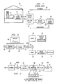
- a PCM upstream network with a voice-band modem connection is illustrated in Figure 1.
- the network 10 includes a V.92 PCM client modem 12 from an end user's personal computer 14 connected to an analog telephone line 16, or channel.
- the analog channel 16 is connected to a telephone company central office (CO) 18 wherein the analog levels are quantized using a ⁇ -law or A-law codec 20.
- a V.92 server modem 26 completes the connection in the upstream direction. Data may transmit in either the downstream direction (server to client modem) 28 or the upstream direction 30 (client to server modem).
- Equalizers For digital symbols transmitted over the analog channel to be reasonably free of intersymbol interference over the frequency spectrum used by the symbols, modems employ adaptive filters called equalizers. Equalization is a technique used to compensate for distortion in analog signal lines. One of the distortions which is compensated for is intersymbol interference. Equalizers in a receiver neutralize intersymbol interference which would cause high bit error rates if left uncompensated. Equalization is accomplished by passing the digital signal through a filter whose tap coefficients are adjusted so that the combination of channel plus equalizer is some known response. When the channel is properly equalized, data can be recovered reliably from the received symbols.
- Modems equalize the incoming signals by employing various types of equalizers include linear equalizers, decision-feedback equalizer, and trellis-based Viterbi equalizers.
- the equalizer taps of a minimum mean-square-error decision-feedback equalizer (MMSE-DFE) can be directly computed by Givens rotations without back-substitution and matrix-vector multiplication, as discussed in the paper "An Improved Fast Algorithm for Computing the MMSE Decision-Feedback Equalizer” by Bin Yang, Int. J. Electron. Commun., 51 (1999) No. 1, 1-8.
- the transmit equalizer 32 is designed to undo the negative effects of the channel so that the same signal, u(n) 36, appears before and after the combination of the equalizer 32 and channel 34.
- the input values, u(n) are chosen from a constellation of points as determined by the server modem 26 (see section 6.4.2 in ITU-T/V.92). Because of the echo, the constellation of points will not correspond exactly to the PCM codec levels. However, it is still true, as in PCM downstream modulation, that there are more constellation points possible at smaller signal levels than at larger levels.
- Digital impairments 38 include digital pads (digital gain) and robbed-bit-signaling (RBS).
- RBS is a technique used in T1 network connections where the least significant bit of each nth data octet is replaced with a control bit by the network for control signaling. For any one RBS link, the frequency of robbed bits through a single T1 connection is one every sixth symbol. This "in-band” signaling is used to indicate things like "off-hook”, “ringing”, “busy signal”, etc. RBS results in data impairment by changing transmitted bit values. RBS must be detected and the signaling bit ignored when present. Another problem with RBS in networks is where the link between two modems includes several different digital legs such that the number of RBS links is variable from one connection to another.
- a reasonable client modem implementation might use a phase-locked loop (PLL) for rough timing recovery and might use receive equalizer adaptation for finer timing recovery.
- PLL phase-locked loop
- the receiver equalizer updates and reacts more quickly than does a PLL.
- An equalizer is used in the PCM upstream receiver of the present invention. However, the equalizer comes after the codec and can not prevent upstream timing drift from adding quantization noise. Finally, power line noise 40 interference comes before the codec 20 in PCM upstream. Cancellation after the codec 20 will not eliminate the added quantization noise and will distort the received signal.
- FIG. 1 is a block diagram illustrating the LMS update setup. Once the estimate of the channel, H_est 50, has converged, the power of the error signal, e k 52, should be close to the average power of the additive noise and quantization noise.
- LMS least mean squares
- RBS 48 Robbed bit signaling 48 is present is nearly all T1 connections but is not present in E1.
- RBS the least significant bit in every 6 th ⁇ -law sample is replaced (or robbed) with signaling information.
- the signaling pattern is never longer than 4 bits long. Therefore, the pattern repeats every 24 ⁇ -law samples.
- the PN3857 test standard allows for up to four RBS links.
- RBS will also affect the constellation design in PCM upstream. When there is RBS, the space between adjacent ⁇ -law samples effectively doubles. Therefore, the phase(s) containing RBS should be detected and tracked.
- RBS detection in the upstream direction can be simplified since the ⁇ -law samples are directly accessed. Over some period where any signal is being received, the least significant bit (LSB) from a block of 24 samples is stored. Then, these bits are compared to the subsequent block of 24 samples.
- the phases on which there is no RBS are expected to vary randomly between 1 and 0. On those samples with RBS, the same values are detected in every block, while the number of differences detected is tracked. If there is no RBS, the probability of k differences in n observations of the LSB is: For 100 observations, the probability of fewer than eight (for example) observed bit differences is ⁇ 10 -19 . RBS is detected if fewer than eight differences are observed on any of the 24 phases.
- samples with RBS can be adjusted to compensate for the average offset. This will affect the identified channel and the designed equalizer.
- RBS will also affect the power of the error signal and the estimated channel.
- the decision region 58 is skewed when RBS is present.
- the decision point 60 is not in the middle 62 of the decision region 58. For example, if the RBS bit is a 0, then positive samples will have an average positive offset caused by the RBS and negative samples will have an average negative offset. Assuming that the echo and additive noise are large enough to make the quantizer error nearly uniform, the extra noise power caused by the offset decision point is 2.4dB.
- the estimated channel using LMS will be affected by RBS. If the RBS pattern is constant (all ones or all zeros), the channel will reach a compromise between the samples with and without RBS. This effect is illustrated in Figure 5 where the measured SNR is plotted for samples with and without RBS depending on the number of RBS links.
- the goal of the upstream equalizer in this invention is to undo the negative effects of the channel on PCM upstream data transmissions.
- the effective channel after the equalization is illustrated in Figure 2.
- the design of the upstream data mode equalizer is chosen from a channel identification rather than by using LMS. There are two main reasons for this. First, the channel typically has nulls at DC and Nyquist creating a wide eigenvalue spread in the channel auto-correlation. This means that the convergence time is very long, taking many seconds. many instances, the equalizer will not converge at all. Second, a decision feedback equalizer designed using LMS with the received samples attempts to minimize the overall error including the quantization noise, which is not the optimal filter. If LMS is used with the recovered channel, the complexity of re-creating the channel is added and the convergence problem still exists.
- FIG. 5 there is illustrated a block diagram of an example of the client modem transmitter 64.
- the equalizer 66 is within the client modem transmitter.
- input signal u(k) 68 which feeds into the client modem transmitter 64.
- Filtered signal y(k) 70 from filter B(D) 72 feeds pre-equalizer W(D) 66.
- Signal v(k) 74 exits W(D) 66 and enters the analog channel H(D) 34, wherein noise 40 is added to the signal u(k).
- Filters B(D) 72 and pre-equalizer W(D) 66 are designed to jointly minimize the power of the error, e k 52, and to minimize the power of the transmit signal, v k 74.
- H is a Toeplitz channel matrix (n ff ⁇ n ff + ⁇ - 1)
- u k is a vector of data input samples of length n ff + ⁇ - 1
- u k- ⁇ is a length n ff vector of input samples delayed by ⁇ .
- the length of the channel is ⁇ .
- the power of the error, e k should be minimized along with minimizing the transmit signal power. Since the feedforward filter, w, is generally spectrally flat, minimizing the transmit power can be achieved by minimizing the power of the filter, w w T . In a zero-forcing DFE, the feedforward filter is an all-pass filter. In the present invention, it will be nearly all-pass and roughly flat.
- H ⁇ +1: ⁇ +nfb represents the ⁇ through ⁇ +n fb th column of the matrix
- H and H ⁇ is the ⁇ th column of the matrix
- I is the identity matrix (a square matrix with dimensions n fb ).
- the choice of the value of ⁇ in the above equation is a tradeoff between intersymbol interference and the power of the pre-equalizer filter which affects the transmit power.
- the possible values of u(k) must be limited to stay within regulatory power limits.
- the receive signal becomes noisier meaning that the space between constellation points needs to be greater, which also limits the data rate.
- the above equation (3) is solved for a number of values of ⁇ and over a variety of filter lengths. Values for ⁇ are chosen and the number of filter taps are selected to maximize the overall data rate.
- the present invention accordingly solves equation (3) with a method based on results from Al-Dhahir and Cioffi, see N. Al-Dhahir, J. Cioffi, "Fast Computation of Channel-Estimate Based Equalizers in Packet Data Transmission,” IEEE Trans. Sig. Proc., Nov. 95, (the "Al-Dhahir Method"), and an efficient algorithm by Yang, see B. Yang, "An Improved Fast Algorithm for Computing the MMSE Decision-Feedback Equalizer," AEU Int. J. Electron. Commun., 51 (1999) No. 1,1-8.
- FIG. 6 An exemplary embodiment of PCM upstream transmission in accordance with the present invention.
- client modem transmitter 64 interconnected to analog channel 34 having channel characteristic H(D).
- Client modem transmitter 64 includes precoder B(D) 72 and pre-equalizer W(D) 66.
- Precoder 72 receives digital data u(n) 36 and outputs precoded dital data signal v(n) 37 that is transmitted over analog channel 34.
- the signal passes through hybrid 42 and is received by the codec 20 in a central office 18. From the codec 20, the signal is received into a ⁇ -law (or A-law in some countries outside the United States) quantizer 78 and is quantized according to the ⁇ -law to a linear output.
- ⁇ -law or A-law in some countries outside the United States
- the digital signal is then transmitted upstream over a digital network 22 to the server modem receiver 80 and received by an echo canceller 82 in a digital PCM modem wherein echo is removed from the signal.
- echo canceller the signal is received by equalizer 84 having characteristic R(X) that outputs equalized signal u(n).
- the length of the feedback filter is increased by 16 taps and the length of the feedforward filter is increased by 16 taps. At this point, if the total number of taps or the number of feedforward taps exceeds the limits, the feedforward filter is shortened by preserving the taps with the most energy.
- Rate renegotiation and retrains are used by both server and client modems to update filters, change rates, and possibly to change the modulation.
- a rate renegotiation is issued to adjust the transmit equalizer and constellation, which may or may not change the upstream data rate.
- the decision about whether or not to issue a rate renegotiation or retrain is made based on detected errors in the trellis decoder.
- the error between the equalizer output and the sliced equalizer output could be used to determine whether or not a rate renegotiation was needed. In PCM upstream, this is not possible. The reason is that the errors will be higher for larger (greater magnitude) constellation points than for the smaller points.
- the error power also depends on the echo. Therefore, the average equalizer error power is meaningless and attempts to weight smaller values more heavily and to take the echo power into account are not reliable.
- a reliable method of detecting the approximate bit error rate is required for determining whether or not a rate renegotiation or retrain is required.
- the trellis search is a common implementation of a maximum likelihood detector.
- the trellis search works by comparing the actual received values with the ideal values calculated along every branch in a trellis.
- the ideal values are based on the code selected. Metrics are kept for every state in the trellis and branch metrics are calculated for every possible branch in the trellis for every received symbol. The branch metrics are added to the state metrics from where the branches originate. The next state is chosen from all the branches leading into that state by selecting the smallest metric.
- an error event is flagged.
- a moving average of the number of errors accumulate and surpass a threshold count, the need to perform a rate renegotiation and expand the constellation is indicated.
- a rate renegotiation is issued to possibly increase the data rate.
- the flag is set to 1, otherwise the flag is set to 0.
- a simple low-pass filter is used to make the determination: If a exceeds some threshold, a fallback is declared; if a falls below another threshold, a fallforward is declared.
- the values of n and the thresholds were determined through off-line simulations with a target bit error rate of 10 -5 .
- the present invention also uses a receiver data mode equalizer in the server modem.
- the receiver data mode equalizer compensates for timing drift in the client transmitter. A small timing drift is tolerable. However, a large phase shift will add considerable quantization noise which can not be compensated by the receive equalizer.
- LMS is used to update the receive equalizer. This equalizer is only 16 taps for the present invention. A smaller number of taps is used because empirical testing determined that the LMS misadjustment was significant for larger filters, and a16-tap filter is sufficient to compensate for timing drift. Other, more severe changes in the channel, can be compensated through a rate renegotiation.
Abstract
Description
- This invention relates to a method and device for providing pulse code modulation (PCM) data transmission for networks, such a network implementing PCM upstream voice-band modem transmissions.
- Personal computers connecting to networks through the public switched telephone system (PSTN) typically use a modem to dial-up a network connection through analog telephone lines. These client, or end user, modems transmit data signals converted to digital source through an analog channel through a network. Due to the increase in data, voice, and facsimile traffic over the telecommunications infrastructure, methods to increase the digital and analog transfer rates through modems over telephone lines are extremely useful and necessary to adhere to International Telecommunication Union (ITU) standards. The Telecommunication Standardization Sector of the ITU (ITU-T) adopted V.34 Recommendation in 1994 to define modem operating speeds from 28.8 kilobyte per second (kbps) up to 33.6 kbps. However, data transfer rates are limited over the PSTN. In modems built to V.34 standards of the International Telecommunications Union (ITU), and all previous voice-band modem standards, carrier-modulated quadrature amplitude modulation (QAM) is used to quantize the analog signals using µ-law (or A-law for some standards outside of the U.S.) pulse code modulation (PCM) codecs. In such a system, the carrier frequency and symbol rate are chosen to match the channel, not the codec. However, in many cases there is a direct digital connection upstream of the analog client modem between a central office (CO) of the PSTN and a server modem on a digital network. PCM modems are built to take advantage of networks used by internet service providers or others connected to the PSTN through a digital connection, such as T1 in the United States and E1 in Europe. PCM modems use either standards for "PCM downstream" modulation, as described in ITU V.90, or "PCM upstream, as described in ITU V.92 recommendations. A connection between a client modem on a local loop of the PSTN and a connection on the digital network can be referred to as a "PCM channel".
- In PCM downstream, data is transmitted in PCM mode downstream from a central office to an end user's analog modem, i.e. from server to client. The digital PCM modem at the server transmits over a digital network in eight bit digital words called octets that correspond to different central office codec output levels. At the client modem's central office, the octets are converted to analog levels which are transmitted over an analog loop. The client PCM modem then converts the analog levels back to digital signals, or pulse code amplitude (PAM) signals, and into equalized digital levels. The equalized digital levels are ideally mapped back into the originally transmitted octets that the octets represent.
- When using PCM downstream modulation, the client modem synchronizes to the central office codec and tries to determine exactly which PCM sample was transmitted in each sample. In codecs throughout the world, the codec clock is 8000Hz. Since there are 255 different µ-law levels and 256 different A-law levels, the data rates could go as high as nearly 64kbps (8 bits/sample at 8000 samples/second). Practically, because the smallest levels are often too small to distinguish and because of regulatory power limits on the transmit signal, the highest data rate is listed as 56kbps although even that is usually higher than what most channels will support. In PCM downstream, the client modem must implement an equalizer to undo the effects of intersymbol interference caused by the channel (the telephone line plus the analog front-end of the codec and client modems) in order to recover the PCM levels.
- In PCM upstream modulation, the client modem transmits analog levels to the digital server modem over an analog loop. The analog levels are modified by the channel characteristics of the analog loop. The modified levels are quantized to form octets by a codec in the central office. In PCM upstream, the channel comes before the codec further limiting the highest possible data rate. The codec then transmits the octets to the PCM server modem over the digital network. At the server modem, the levels transmitted by the client are demodulated from the octets, thereby recovering the data sent from the client modem.
- If the client modem were simply to transmit PCM levels, the channel would distort the levels so that when it reached the codec, they would not resemble the transmitted levels at all. The server modem is not able to equalize the receive signals until after the codec and therefore can not limit the effect of quantization noise. In order to take advantage of the PCM codec in the upstream direction, the client modem must implement an equalizer in the transmitter to undo the effects of intersymbol interference.
- Some patents in the field of PCM upstream transmissions include the following: U.S. Patent No. 6,173,015 B1, Device And Method For Precoding Data Signals For PCM Transmission, that teaches preceding a sequence of analog levels transmitted over an analog channel, which modifies the transmitted analog levels, to a quantization device that includes a mapping device for mapping data bits to be transmitted to a sequence of equivalence classes, a constellation point selector interconnected to the mapping device which selects a constellation point in each equivalence class to represent the data bits to be transmitted and which transmits a level that produces the selected constellation point at an input to the quantization device; U.S. Patent No. 6,181,752 B1, Device And Method For Detecting PCM Upstream Digital Impairments In A Communication Network, that teaches detecting digital impairments affecting an upstream pulse code modulation channel in a digital communications network by receiving a random sequence of digital values selected from a constellation of digital values transmitted over the upstream PCM channel of the digital communications network, establishing distributions of the received digital values, and deriving from the distributions the types of robbed bit signaling and digital loss affecting the upstream PCM channel of the digital communication network for each time interval; U.S. Patent 6,198,776 B1, Device And Method For Precoding Data Signals For PCM Transmission, that teaches a transmitter for transmitting a sequence of analog levels over an analog channel to a quantization device, wherein the analog channel modifies the transmitted analog levels; U.S. Patent 6,266,376 B1, System And Method For Adjusting PCM Data Frames For Robbed Bit Signaling In A Telephone Network, that teaches shifting the relative phases of a PCM data frame and a network RBS frame by one or more symbols to determine whether or not RBS is present; and U.S. Patent 6,201,836 B1, Method And Apparatus For Combining A Trellis Code Scheme With A Pre-Coding Scheme For Data Signals, that teaches a system that receives input bits from a user that define an equivalence class which has at least one constellation point, wherein one of the constellation points in the equivalence class is chosen to represent an output of a channel and a redundancy bit is calculated from the output of the channel and is used to define a next equivalence class for the system.
- Recommendation V.92 states that the convolutional encoders from Recommendation V.34 shall be used for V.92. ITU-T Recommendation V.34 are standards for a modem operating at data signaling rates of up to 33,600 bits/s for use on the general switched telephone network and on leased point-to-point 2-wire telephone type circuits. The standard utilizes quadrature amplitude modulation for each channel with synchronous line transmission at selectable symbol rates including the mandatory rates of 2400, 3000, 3200 symbols/s and the optional rates of 2743, 2800 and 3429 symbols/s. The standard may use trellis coding for all data signaling rates. Trellis encoding is a method for improving noise immunity using a convolutional coder to select a sequence of subsets in a partitioned signal constellation. The trellis encoders used in the ITU recommendation are used in a feedback structure where the inputs to the trellis encoder are derived from the signal points.
- Trellis coded modulation (TCM) is one of the coding standards recommended under the V.34 modem communications standard. Trellis codes using lattices of dimensions larger than two have been constructed and have several advantages. Two dimensional (2D) symbols are grouped in pairs to form four-dimensional (4D) symbol intervals. Multidimensional trellis code signals as a basis for signal constellations are a theoretical concept, since, in practice, multidimensional signals are transmitted as sequences of one or two dimensional signals. Doubling the constellation size reduces the minimum distance within the constellation, and this reduction has to be compensated for by the code before any coding gain can be achieved. Using a 4D signal set causes the constituent 2D constellations to be expanded by a factor of only square root of two, having half a bit of redundancy per 2D constellation.
- The decoding operation comprises finding the correct path through the trellis that most closely represents the received binary sequence. The decoder finds a path for the received binary sequence that has the minimum Euclidian distance from the received sequence. The iterative procedure accomplishing the decoding is the Viterbi algorithm. The algorithm uses forward dynamic programming to select the best, or minimum distance, path through a trellis. At each node, in the trellis, the only path retained is the best path, therefore limiting the number of retained paths at any time instant to the total number of trellis nodes at that time.
- There are a number of factors that limit the PCM upstream data rate more than the PCM downstream data rate and provide additional challenges. Regulatory limits on the client modem transmit power mean that the higher the upstream channel attenuation, the lower the upstream data rate. In the downstream direction, only the signal-to-noise ratio (SNR) limits downstream performance. The echo from the downstream signal is added before the codec. Even a perfect echo canceller in the server modem can not remove the quantization noise caused by the echo. The equalizer in the client transmitter can not continually adapt to changing channel conditions as can the receive equalizer used for PCM downstream. The only way to adapt the transmit equalizer in V.92 is for the server to notify the client through a rate renegotiation. The timing recovery done by the client modem in the upstream direction is more difficult that in the downstream direction.
- Due to these and other problems in PCM upstream transmissions, the levels transmitted by the client PCM modem are modified. Since these modified levels are quantized to form octets by the codec, and not the levels that are actually transmitted, it can be difficult for the server modem to accurately determine from the octets the data being transmitted by the client modem.
- Therefore, a need exists for a device and method for undoing the negative effects of the channel and network interferences with PCM upstream transmissions.
- The invention relates to a method and device for providing pulse code modulation (PCM) data transmission for networks, such a network implementing PCM upstream voice-band modem transmissions. More specifically, the invention establishes a channel for upstream pulse code modulation (PCM) in a digital communications network is described. The invention optimizes upstream data rate rates for data transmissions in a network under V.92 standards between a client modem a server modem.
- For digital communications between modems sent over analog lines in the public service telephone network (PSTN) to be reasonably free of interference, modems must employ adaptive filters. To design the adaptive filters, noise and robbed bit signaling (RBS) must be accounted for. RBS affects the power of the error in digital signals and estimates of the channel.
- The upstream data mode upstream equalizer is chosen from a channel identification rather than using a least mean squares method. The estimate of the channel is affected by RBS and other additive noise, including quantization noise. The upstream equalizer is designed to undo the negative effects of the channel. The analog modem transmitter structure utilizes filters to jointly minimize the power of the error in the channel and to minimize the power of the transmit signal. Minimizing the transmit signal power can be achieved by minimizing the power of the pre-equalizer filter. Noise is not addressed when minimizing the power of the filter because noise is added after the equalizer and the equalizer will not affect its power. The noise is a combination of additive noise and noise from intersymbol interference. The Lagrange multiplier is used in a square matrix to solve for a feedforward filter. The choice of the value of the Lagrange multiplier is a tradeoff between intersymbol interference and the power of the pre-equalizer filter, which affects transmit power. To solve the problem for minimizing the power, an efficient reported algorithm for decision-feedback equalizers and reported results of channel-estimate based equalizers.
- A receiver data mode equalizer is used in the server, or digital, modem that compensates for small misadjustments caused by timing drift from the client modem. A least mean squares method is used to update the receiver equalizer. Severe changes in the channel are compensated through a rate renegotiation.
- The described method detects and corrects errors in transmissions with a trellis search in a decoder of said server modem using a low-pass filter to track error events in said trellis. The method issues a fallback on the trellis if error calculations exceed a predetermined threshold and a fallforward if error calculations fall below a second predetermined threshold.
- Preferred embodiments of the invention are discussed hereinafter with reference to the drawings, in which:
- Figure 1 is a diagram of a PCM a communications network;
- Figure 2 is a diagram of a PCM upstream channel;
- Figure 3 is a PCM channel with robbed bit signaling;
- Figure 4 is an example of quantization modified by robbed bit signaling;
- Figure 5 is a flowchart of the client modem transmitter and the PCM channel;
- Figure 6 is a diagram of the upstream receiver; and
- Figure 7 is an illustration of a trellis branch.
-
- There is described herein a technique for equalizer designs and channel error detections for a PCM upstream data transmission between a digital PCM server modem and a PCM analog client modem.
- When connecting two modems over the public switched telephone network (PSTN), digital data from a central office (CO) often must be translated from digital signals at the server modem into analog tones for transmission over a local analog line to a client modem. At each client modem, the received analog waveform is sampled and quantized by an analog to digital convertor (AID). A PCM upstream network with a voice-band modem connection is illustrated in Figure 1. The
network 10 includes a V.92PCM client modem 12 from an end user'spersonal computer 14 connected to ananalog telephone line 16, or channel. Theanalog channel 16 is connected to a telephone company central office (CO) 18 wherein the analog levels are quantized using a µ-law orA-law codec 20. There is also adigital network 22 which is interconnected to theCO 18 and to the digital transmission channel, which may comprise a T1, E1, orISDN line 24. A V.92server modem 26 completes the connection in the upstream direction. Data may transmit in either the downstream direction (server to client modem) 28 or the upstream direction 30 (client to server modem). - For digital symbols transmitted over the analog channel to be reasonably free of intersymbol interference over the frequency spectrum used by the symbols, modems employ adaptive filters called equalizers. Equalization is a technique used to compensate for distortion in analog signal lines. One of the distortions which is compensated for is intersymbol interference. Equalizers in a receiver neutralize intersymbol interference which would cause high bit error rates if left uncompensated. Equalization is accomplished by passing the digital signal through a filter whose tap coefficients are adjusted so that the combination of channel plus equalizer is some known response. When the channel is properly equalized, data can be recovered reliably from the received symbols. Modems equalize the incoming signals by employing various types of equalizers include linear equalizers, decision-feedback equalizer, and trellis-based Viterbi equalizers. The equalizer taps of a minimum mean-square-error decision-feedback equalizer (MMSE-DFE) can be directly computed by Givens rotations without back-substitution and matrix-vector multiplication, as discussed in the paper "An Improved Fast Algorithm for Computing the MMSE Decision-Feedback Equalizer" by Bin Yang, Int. J. Electron. Commun., 51 (1999) No. 1, 1-8.
- Referring to Figure 2, there is illustrated in block diagram the effective PCM
upstream channel 34. In this figure, the transmitequalizer 32 is designed to undo the negative effects of the channel so that the same signal, u(n) 36, appears before and after the combination of theequalizer 32 andchannel 34. The input values, u(n), are chosen from a constellation of points as determined by the server modem 26 (see section 6.4.2 in ITU-T/V.92). Because of the echo, the constellation of points will not correspond exactly to the PCM codec levels. However, it is still true, as in PCM downstream modulation, that there are more constellation points possible at smaller signal levels than at larger levels. -
Digital impairments 38 include digital pads (digital gain) and robbed-bit-signaling (RBS). RBS is a technique used in T1 network connections where the least significant bit of each nth data octet is replaced with a control bit by the network for control signaling. For any one RBS link, the frequency of robbed bits through a single T1 connection is one every sixth symbol. This "in-band" signaling is used to indicate things like "off-hook", "ringing", "busy signal", etc. RBS results in data impairment by changing transmitted bit values. RBS must be detected and the signaling bit ignored when present. Another problem with RBS in networks is where the link between two modems includes several different digital legs such that the number of RBS links is variable from one connection to another. - As mentioned previously, locking the upstream transmitter clock to the CO clock is more challenging than doing timing recovery in the downstream direction. A reasonable client modem implementation might use a phase-locked loop (PLL) for rough timing recovery and might use receive equalizer adaptation for finer timing recovery. Typically, the receiver equalizer updates and reacts more quickly than does a PLL. An equalizer is used in the PCM upstream receiver of the present invention. However, the equalizer comes after the codec and can not prevent upstream timing drift from adding quantization noise. Finally,
power line noise 40 interference comes before thecodec 20 in PCM upstream. Cancellation after thecodec 20 will not eliminate the added quantization noise and will distort the received signal. - To design the data mode upstream equalizer for PCM upstream, channel identification is performed both during V.92 training events TRN1u and TRN2u. This provides adequate time for the channel to converge. An unbiased channel identification can be performed using least mean squares (LMS). The length of the channel is 96 samples, and the filters will converge in less than 2 seconds with LMS. Figure 3 is a block diagram illustrating the LMS update setup. Once the estimate of the channel,
H_est 50, has converged, the power of the error signal,e k 52, should be close to the average power of the additive noise and quantization noise. - Robbed bit signaling (RBS) 48 is present is nearly all T1 connections but is not present in E1. In RBS, the least significant bit in every 6th µ-law sample is replaced (or robbed) with signaling information. The signaling pattern is never longer than 4 bits long. Therefore, the pattern repeats every 24 µ-law samples. There can also be more than one RBS signaling channel. One channel might affect
samples samples 3, 9, 15, 21, .... The PN3857 test standard allows for up to four RBS links. RBS will also affect the constellation design in PCM upstream. When there is RBS, the space between adjacent µ-law samples effectively doubles. Therefore, the phase(s) containing RBS should be detected and tracked. - RBS detection in the upstream direction can be simplified since the µ-law samples are directly accessed. Over some period where any signal is being received, the least significant bit (LSB) from a block of 24 samples is stored. Then, these bits are compared to the subsequent block of 24 samples. The phases on which there is no RBS are expected to vary randomly between 1 and 0. On those samples with RBS, the same values are detected in every block, while the number of differences detected is tracked. If there is no RBS, the probability of k differences in n observations of the LSB is:For 100 observations, the probability of fewer than eight (for example) observed bit differences is ∼10-19. RBS is detected if fewer than eight differences are observed on any of the 24 phases.

- Once RBS is detected, samples with RBS can be adjusted to compensate for the average offset. This will affect the identified channel and the designed equalizer. The received samples can be adjusted by converting to a linear sample halfway between the RBS sample and the RBS sample with the RBS bit inverted. For example, if a sample known to have RBS inserted is received with value µ=50, then the RBS bit was 0. The linear value corresponding to µ=50 is-3644 and to µ=51 is -3516. The linear sample should be set to the average of -3580.
- RBS will also affect the power of the error signal and the estimated channel. Referring to Figure 4, the
decision region 58 is skewed when RBS is present. Thedecision point 60 is not in the middle 62 of thedecision region 58. For example, if the RBS bit is a 0, then positive samples will have an average positive offset caused by the RBS and negative samples will have an average negative offset. Assuming that the echo and additive noise are large enough to make the quantizer error nearly uniform, the extra noise power caused by the offset decision point is 2.4dB. - The estimated channel using LMS will be affected by RBS. If the RBS pattern is constant (all ones or all zeros), the channel will reach a compromise between the samples with and without RBS. This effect is illustrated in Figure 5 where the measured SNR is plotted for samples with and without RBS depending on the number of RBS links. In the following formula, variable k is an index from 0 to 5 representing one of the six RBS phases. Then
- The goal of the upstream equalizer in this invention is to undo the negative effects of the channel on PCM upstream data transmissions. The effective channel after the equalization is illustrated in Figure 2. In the present invention, the design of the upstream data mode equalizer is chosen from a channel identification rather than by using LMS. There are two main reasons for this. First, the channel typically has nulls at DC and Nyquist creating a wide eigenvalue spread in the channel auto-correlation. This means that the convergence time is very long, taking many seconds. many instances, the equalizer will not converge at all. Second, a decision feedback equalizer designed using LMS with the received samples attempts to minimize the overall error including the quantization noise, which is not the optimal filter. If LMS is used with the recovered channel, the complexity of re-creating the channel is added and the convergence problem still exists.
- In Figure 5 there is illustrated a block diagram of an example of the
client modem transmitter 64. Theequalizer 66 is within the client modem transmitter. In Figure 5, there is included input signal u(k) 68 which feeds into theclient modem transmitter 64. Filtered signal y(k) 70 from filter B(D) 72 feeds pre-equalizer W(D) 66. Signal v(k) 74 exits W(D) 66 and enters the analog channel H(D) 34, whereinnoise 40 is added to the signal u(k). Filters B(D) 72 and pre-equalizer W(D) 66 are designed to jointly minimize the power of the error,e k 52, and to minimize the power of the transmit signal,v k 74. - Writing an equation for the error results inwhere w and b are finite length row vectors (length nff and nfb respectively), H is a Toeplitz channel matrix (nff × nff + ν - 1), uk is a vector of data input samples of length nff + ν - 1, and uk- Δ is a length nff vector of input samples delayed by Δ. The length of the channel is ν.

- The power of the error, ek should be minimized along with minimizing the transmit signal power. Since the feedforward filter, w, is generally spectrally flat, minimizing the transmit power can be achieved by minimizing the power of the filter, w wT. In a zero-forcing DFE, the feedforward filter is an all-pass filter. In the present invention, it will be nearly all-pass and roughly flat. The Lagrange multiplier is used to solve this problem. By setting d(e)/d [w b] + λd(w wT)/d[w b] = 0 where λ is some constant and solve for w and b, subject to the constraint that b(0) = 1 (unit tap constraint) to prevent the trivial solution w = 0.is found where H Δ+1:Δ+nfb represents the Δ through Δ+nfb th column of the matrix, H and HΔ is the Δth column of the matrix, H, and I is the identity matrix (a square matrix with dimensions nfb). This solves the equation for the case when the input sequence, u(k), is independent and identically distributed (as is approximately the case here). The noise does not appear in this equation because it is added after the equalizer and the equalizer will not affect its power. The noise is the combination of the additive noise and any noise from intersymbol interference caused by imperfect equalization. The choice of the value of λ in the above equation is a tradeoff between intersymbol interference and the power of the pre-equalizer filter which affects the transmit power. As the power of the pre-equalizer filter grows, the possible values of u(k) must be limited to stay within regulatory power limits. However, as intersymbol interference grows, the receive signal becomes noisier meaning that the space between constellation points needs to be greater, which also limits the data rate. The above equation (3) is solved for a number of values of λ and over a variety of filter lengths. Values for λ are chosen and the number of filter taps are selected to maximize the overall data rate.

- The present invention accordingly solves equation (3) with a method based on results from Al-Dhahir and Cioffi, see N. Al-Dhahir, J. Cioffi, "Fast Computation of Channel-Estimate Based Equalizers in Packet Data Transmission," IEEE Trans. Sig. Proc., Nov. 95, (the "Al-Dhahir Method"), and an efficient algorithm by Yang, see B. Yang, "An Improved Fast Algorithm for Computing the MMSE Decision-Feedback Equalizer," AEU Int. J. Electron. Commun., 51 (1999) No. 1,1-8. This method solves equation (3) for the special case where Δ = nff-1 and nfb = ν. This restriction does not significantly affect performance. Using Yang, a two row matrix is created:where the values, h, are the result of the channel ID and λ is the Lagrange multiplier constant that is empirically selected based on simulation results. The left part of the matrix has ν columns. Performing nff Givens rotations, the matrix A contains
 which is desired result.
- The Givens rotations are performed using the algorithm described in W. M. Gentleman, "Least Squares Computations by Givens Transformations Without Square Roots," J. Inst. Maths Applics, 1973, pages 329-336.
- There is illustrated in Figure 6 an exemplary embodiment of PCM upstream transmission in accordance with the present invention. In the diagram there is included a
client modem transmitter 64 interconnected toanalog channel 34 having channel characteristic H(D).Client modem transmitter 64 includes precoder B(D) 72 and pre-equalizer W(D) 66.Precoder 72 receives digital data u(n) 36 and outputs precoded dital data signal v(n) 37 that is transmitted overanalog channel 34. The signal passes throughhybrid 42 and is received by thecodec 20 in acentral office 18. From thecodec 20, the signal is received into a µ-law (or A-law in some countries outside the United States) quantizer 78 and is quantized according to the µ-law to a linear output. The digital signal is then transmitted upstream over adigital network 22 to the server modem receiver 80 and received by anecho canceller 82 in a digital PCM modem wherein echo is removed from the signal. After echo canceller, the signal is received byequalizer 84 having characteristic R(X) that outputs equalized signal u(n). - If a power line interference adjustment filter is used, the length of the feedback filter is increased by 16 taps and the length of the feedforward filter is increased by 16 taps. At this point, if the total number of taps or the number of feedforward taps exceeds the limits, the feedforward filter is shortened by preserving the taps with the most energy.
- Rate renegotiation and retrains are used by both server and client modems to update filters, change rates, and possibly to change the modulation. In the present invention, for PCM upstream server implementation, a rate renegotiation is issued to adjust the transmit equalizer and constellation, which may or may not change the upstream data rate. The decision about whether or not to issue a rate renegotiation or retrain is made based on detected errors in the trellis decoder.
- In V.34 and V.90 modulations, the error between the equalizer output and the sliced equalizer output could be used to determine whether or not a rate renegotiation was needed. In PCM upstream, this is not possible. The reason is that the errors will be higher for larger (greater magnitude) constellation points than for the smaller points. The error power also depends on the echo. Therefore, the average equalizer error power is meaningless and attempts to weight smaller values more heavily and to take the echo power into account are not reliable.
- A reliable method of detecting the approximate bit error rate is required for determining whether or not a rate renegotiation or retrain is required. Using the trellis search required for the decoder allows reliable error detection. The trellis search is a common implementation of a maximum likelihood detector. The trellis search works by comparing the actual received values with the ideal values calculated along every branch in a trellis. A branch connects one state at symbol=n with another state at symbol=n+1. Typically there are more than one branches that enter and leave each state. The ideal values are based on the code selected. Metrics are kept for every state in the trellis and branch metrics are calculated for every possible branch in the trellis for every received symbol. The branch metrics are added to the state metrics from where the branches originate. The next state is chosen from all the branches leading into that state by selecting the smallest metric.
- The coding gain of the trellis search comes because the decision is delayed by tracing back through the trellis. An example 4-state trellis with only the surviving paths is shown in Figure 7. In this example, assume that a starting point at any state at symbol=4. If the path is traced back to symbol=0, all paths lead to state S1. This means that S1 is the most likely state at symbo1=0.
- Assume, for example, that the smallest metric at symbol=4 was state S0. Assume trace-backs are performed in blocks of 4 samples. Then assume at symbol=8 the path is traced back from any state. At symbo1=4, the most likely state was actually S1. Discrepancies such as those in the example do not necessarily indicate an error, but they do indicate that the noise is sufficient to have caused a symbol-by-symbol error.
- When a discrepancy is found between the best estimate at the final state in the trellis during the previous block and the best estimate at the same state by having traced back from the current block, an error event is flagged. When a moving average of the number of errors accumulate and surpass a threshold count, the need to perform a rate renegotiation and expand the constellation is indicated. Similarly, when a discrepancy is rarely detected over a long period of time, a smaller constellation is preferred and a rate renegotiation is issued to possibly increase the data rate.
When an error event is logged, the flag is set to 1, otherwise the flag is set to 0. A simple low-pass filter is used to make the determination:If a exceeds some threshold, a fallback is declared; if a falls below another threshold, a fallforward is declared. The values of n and the thresholds were determined through off-line simulations with a target bit error rate of 10-5.
- The present invention also uses a receiver data mode equalizer in the server modem. The receiver data mode equalizer compensates for timing drift in the client transmitter. A small timing drift is tolerable. However, a large phase shift will add considerable quantization noise which can not be compensated by the receive equalizer. LMS is used to update the receive equalizer. This equalizer is only 16 taps for the present invention. A smaller number of taps is used because empirical testing determined that the LMS misadjustment was significant for larger filters, and a16-tap filter is sufficient to compensate for timing drift. Other, more severe changes in the channel, can be compensated through a rate renegotiation.
- The above discussion is meant to be illustrative of the principles and various embodiments of the present invention. Numerous variations and modifications will become apparent to those skilled in the art once the above disclosure is fully appreciated. It is intended that the following claims be interpreted to embrace all such variations and modifications.
Claims (10)
- A method for pulse code modulation upstream data transmissions in a network between a client modem and a server modem, comprising:performing channel identification; andcalculating the client modem transmit upstream equalizer in closed form using a decision-feedback filter solution that jointly optimizes the amount of intersymbol interference and the transmit power.
- The method of claim 1, further comprising:where w and b are finite length row vectors of length nff and nfb, respectively, H is a Toeplitz channel matrix (nff × nff + ν - 1), uk is a vector of data input samples of length nff + ν - 1, uk-Δ is a length nff vector of input samples delayed by Δ, and the length of the channel is ν.identification of an error signal, ek, in said equalizer with filters w and b within said equalizer with the formula

- The method of claim 2, further comprising:where λ is some constant and is solved for w and b using matrixmaximizing the overall performance by jointly minimizing the power of the error signal and the power of the transmit filter, w, subject to the constraint b(0) = 1; wherein the joint minimization is determined usingwhere λ is the Lagrange multiplier constant, HΔ+1:Δ+nfb represents the Δ through Δ+nfb th column of the matrix, H, I is the identity matrix (a square matrix with dimensions nfb), wherein the Lagrange multiplier λ and the number of filter taps are selected to maximize the overall data rate.

- The method of claim 3, wherein:said matrix is solved where Δ = nff-1 and nfb = ν using theAl-Dhahir method.
- A method for pulse code modulation upstream data transmissions in a network between a client modem a server modem, comprising:performing channel identification;equalizing said transmissions using a closed form upstream data mode equalizer in said client modem based on said channel identification;detecting errors in said transmissions with a trellis code decoder;using a receiver data mode equalizer to compensate for timing drift and channel variations in said client modem transmitter.
- The method of any of claims 2 to 5, wherein:said step of channel identification is performed by estimating the channel, and converging the channel using least mean squares.
- The method of claim 6, wherein:said step of estimating the channel includes detection of robbed bit signaling; and linearly interpolating between possible samples when robbed bit signaling is present.
- The method of any of claims 5 to 7, further comprising:indicating a need to perform a rate renegotiation and expand a constellation when a number of possible errors accumulated in a trellis search using said trellis code decoder to surpass a predetermined threshold count.
- A method for assessing bit error rate performance in a network between a client modem and a server modem, comprising:approximating the bit error rate by observing discrepancies in a trace-back path in a Viterbi decoder as current sample time is updated.
- The method of claim 9, further comprising:assigning a flag of "0" or "1" at regular time intervals depending on if a discrepancy is noted in the final trace-back state in the Viterbi decoder between the two times;applying a low-pass filter to the flag; andderiving the approximate bit error rate.
Applications Claiming Priority (2)
| Application Number | Priority Date | Filing Date | Title |
|---|---|---|---|
| US118377 | 2002-04-09 | ||
| US10/118,377 US7321618B2 (en) | 2002-04-09 | 2002-04-09 | PCM upstream data transmission server |
Publications (2)
| Publication Number | Publication Date |
|---|---|
| EP1370037A2 true EP1370037A2 (en) | 2003-12-10 |
| EP1370037A3 EP1370037A3 (en) | 2007-05-30 |
Family
ID=28674414
Family Applications (1)
| Application Number | Title | Priority Date | Filing Date |
|---|---|---|---|
| EP03100950A Withdrawn EP1370037A3 (en) | 2002-04-09 | 2003-04-08 | PCM upstream data transmission server |
Country Status (2)
| Country | Link |
|---|---|
| US (1) | US7321618B2 (en) |
| EP (1) | EP1370037A3 (en) |
Families Citing this family (2)
| Publication number | Priority date | Publication date | Assignee | Title |
|---|---|---|---|---|
| JP4679096B2 (en) * | 2004-08-17 | 2011-04-27 | Necマグナスコミュニケーションズ株式会社 | Large-scale integrated circuit for data communication, data communication apparatus, data communication system, and data communication method |
| WO2007001205A1 (en) * | 2005-06-29 | 2007-01-04 | Intel Corporation | Precoder construction and equalization |
Citations (1)
| Publication number | Priority date | Publication date | Assignee | Title |
|---|---|---|---|---|
| EP1124359A2 (en) | 2000-02-10 | 2001-08-16 | Texas Instruments Incorporated | Laroia-Tretter-Farvardin precoder for PCM modems |
Family Cites Families (17)
| Publication number | Priority date | Publication date | Assignee | Title |
|---|---|---|---|---|
| US5394392A (en) * | 1992-12-14 | 1995-02-28 | At&T Corp. | Method for transferring information using modems |
| US5754353A (en) * | 1993-07-01 | 1998-05-19 | Cirrus Logic, Inc. | Channel quality circuit in a sampled amplitude read channel |
| US5784392A (en) * | 1995-06-26 | 1998-07-21 | Nokia Mobile Phones Ltd. | Viterbi decoder with l=2 best decoding paths |
| US5784405A (en) * | 1996-08-23 | 1998-07-21 | Paradyne Corporation | Noncooperative feedback system and method for a compensation system associated with a transmitter or CODEC |
| US6198776B1 (en) * | 1996-11-13 | 2001-03-06 | Motorola Inc. | Device and method for precoding data signals for PCM transmission |
| US6005898A (en) * | 1997-03-12 | 1999-12-21 | Interdigital Technology Corporation | Multichannel viterbi decoder |
| US6606355B1 (en) * | 1997-05-12 | 2003-08-12 | Lucent Technologies Inc. | Channel coding in the presence of bit robbing |
| US6445733B1 (en) * | 1997-10-03 | 2002-09-03 | Conexant Systems, Inc. | Method of and apparatus for performing line characterization in a non-idle mode in a subscriber line communication system |
| DE69839814D1 (en) * | 1997-12-29 | 2008-09-11 | Motorola Inc | METHOD AND APPARATUS FOR SELECTING A CONSTELLATION POINT FOR EACH GROUP OF DATA BITS WHICH SHOULD BE TRANSMITTED BY AN ANALOG PCM MODEM |
| US6181752B1 (en) * | 1997-12-29 | 2001-01-30 | Motorola Inc. | Device and method for detecting PCM upstream digital impairments in a communication network |
| US6201842B1 (en) * | 1997-12-29 | 2001-03-13 | Motorola Inc. | Device and method for detecting PCM upstream digital impairments in a communication network |
| US6141388A (en) * | 1998-03-11 | 2000-10-31 | Ericsson Inc. | Received signal quality determination method and systems for convolutionally encoded communication channels |
| US6201836B1 (en) * | 1999-01-20 | 2001-03-13 | Motorola Inc. | Method and apparatus for combining a Trellis coding scheme with a pre-coding scheme for data signals |
| US6341360B1 (en) * | 1999-03-08 | 2002-01-22 | International Business Machines Corporation | Decision feedback equalizers, methods, and computer program products for detecting severe error events and preserving equalizer filter characteristics in response thereto |
| US6570917B1 (en) * | 1999-03-10 | 2003-05-27 | Agere Systems Inc. | Equalizer training in the presence of network impairment |
| US6662322B1 (en) * | 1999-10-29 | 2003-12-09 | International Business Machines Corporation | Systems, methods, and computer program products for controlling the error rate in a communication device by adjusting the distance between signal constellation points |
| US6266376B1 (en) * | 2000-02-04 | 2001-07-24 | Motorola, Inc. | System and method for adjusting PCM data frames for robbed bit signaling in a telephone network |
-
2002
- 2002-04-09 US US10/118,377 patent/US7321618B2/en active Active
-
2003
- 2003-04-08 EP EP03100950A patent/EP1370037A3/en not_active Withdrawn
Patent Citations (1)
| Publication number | Priority date | Publication date | Assignee | Title |
|---|---|---|---|---|
| EP1124359A2 (en) | 2000-02-10 | 2001-08-16 | Texas Instruments Incorporated | Laroia-Tretter-Farvardin precoder for PCM modems |
Non-Patent Citations (2)
| Title |
|---|
| RAJIV LAROIA, CODING FOR INTERSYMBOL INTERFERENCE CHANNELS-COMBINED CODING AND PRECODING |
| W. M. GENTLEMAN: "Least Squares Computations by Givens Transformations Without Square Roots", J. INST. MATHS APPLIES, 1973, pages 329 - 336 |
Also Published As
| Publication number | Publication date |
|---|---|
| US7321618B2 (en) | 2008-01-22 |
| US20030189976A1 (en) | 2003-10-09 |
| EP1370037A3 (en) | 2007-05-30 |
Similar Documents
| Publication | Publication Date | Title |
|---|---|---|
| US7526053B1 (en) | Sequence detector using viterbi algorithm with soft output error correction | |
| US6775335B2 (en) | Method and apparatus for equalization and tracking of coded digital communications signals | |
| US5742642A (en) | Signal processing method and apparatus for reducing equalizer error | |
| US6002713A (en) | PCM modem equalizer with adaptive compensation for robbed bit signalling | |
| US5056117A (en) | Decision feedback equalization with trellis coding | |
| US6341360B1 (en) | Decision feedback equalizers, methods, and computer program products for detecting severe error events and preserving equalizer filter characteristics in response thereto | |
| US6665336B2 (en) | Modems, methods, and computer program products for selecting an optimum data rate using error signals representing the difference between the output of an equalizer and the output of a slicer or detector | |
| US6505222B1 (en) | Systems methods and computer program products for controlling undesirable bias in an equalizer | |
| US7003030B2 (en) | Receivers, methods, and computer program products for an analog modem that receives data signals from a digital modem | |
| US6850563B1 (en) | Data slicer for combined trellis decoding and equalization | |
| US7239664B2 (en) | Method for selecting the data rate for PCM upstream transmission | |
| KR100416888B1 (en) | System, device and method for pcm upstream transmission utilizing an optimized transmit constellation | |
| US6389064B1 (en) | Modems, methods, and computer program products for identifying a signaling alphabet in variance with an ideal alphabet due to digital impairments | |
| US6721279B1 (en) | Method and apparatus for adaptive PCM level estimation and constellation training | |
| US6381267B1 (en) | Modems, methods, and computer program products for falling back to a lower data rate protocol upon detecting abnormal line conditions during startup | |
| US7321618B2 (en) | PCM upstream data transmission server | |
| US7280592B1 (en) | Hybrid digital/analog device | |
| US6414989B1 (en) | Upstream PCM transmission for a modem system | |
| WO1998009400A1 (en) | Receiving and equalizing signals for high-speed data transmission | |
| US6600780B1 (en) | Apparatus and method for adapting a filter of an analog modem | |
| WO1998013979A1 (en) | System and device for, and method of, processing baseband signals to combat isi and non-linearities in a communication system | |
| US20030194030A1 (en) | Power line interference compensation in PCM upstream transmissions | |
| US6865239B1 (en) | Deterministic distortion insensitive adaptive receiver using decision updating | |
| JP2003530755A (en) | Method for transmitting digital data to an A / D converter via an analog channel | |
| Jimaa | Data transmission over ADPCM links |
Legal Events
| Date | Code | Title | Description |
|---|---|---|---|
| PUAI | Public reference made under article 153(3) epc to a published international application that has entered the european phase |
Free format text: ORIGINAL CODE: 0009012 |
|
| AK | Designated contracting states |
Kind code of ref document: A2 Designated state(s): AT BE BG CH CY CZ DE DK EE ES FI FR GB GR HU IE IT LI LU MC NL PT SE SI SK TR |
|
| AX | Request for extension of the european patent |
Extension state: AL LT LV MK RO |
|
| RTI1 | Title (correction) |
Free format text: PCM UPSTREAM DATA TRANSMISSION SERVER |
|
| PUAL | Search report despatched |
Free format text: ORIGINAL CODE: 0009013 |
|
| AK | Designated contracting states |
Kind code of ref document: A3 Designated state(s): AT BE BG CH CY CZ DE DK EE ES FI FR GB GR HU IE IT LI LU MC NL PT SE SI SK TR |
|
| AX | Request for extension of the european patent |
Extension state: AL LT LV MK RO |
|
| RIC1 | Information provided on ipc code assigned before grant |
Ipc: H04L 1/00 20060101ALI20070424BHEP Ipc: H04L 25/03 20060101AFI20030827BHEP |
|
| 17P | Request for examination filed |
Effective date: 20071130 |
|
| AKX | Designation fees paid |
Designated state(s): DE FR GB |
|
| 17Q | First examination report despatched |
Effective date: 20100422 |
|
| STAA | Information on the status of an ep patent application or granted ep patent |
Free format text: STATUS: THE APPLICATION IS DEEMED TO BE WITHDRAWN |
|
| 18D | Application deemed to be withdrawn |
Effective date: 20140211 |