EP1369898A2 - Magnetic field generator for magnetron plasma - Google Patents
Magnetic field generator for magnetron plasma Download PDFInfo
- Publication number
- EP1369898A2 EP1369898A2 EP03012176A EP03012176A EP1369898A2 EP 1369898 A2 EP1369898 A2 EP 1369898A2 EP 03012176 A EP03012176 A EP 03012176A EP 03012176 A EP03012176 A EP 03012176A EP 1369898 A2 EP1369898 A2 EP 1369898A2
- Authority
- EP
- European Patent Office
- Prior art keywords
- magnetic field
- field generator
- magnetic
- vacuum chamber
- members
- Prior art date
- Legal status (The legal status is an assumption and is not a legal conclusion. Google has not performed a legal analysis and makes no representation as to the accuracy of the status listed.)
- Granted
Links
Images




Classifications
-
- H—ELECTRICITY
- H05—ELECTRIC TECHNIQUES NOT OTHERWISE PROVIDED FOR
- H05H—PLASMA TECHNIQUE; PRODUCTION OF ACCELERATED ELECTRICALLY-CHARGED PARTICLES OR OF NEUTRONS; PRODUCTION OR ACCELERATION OF NEUTRAL MOLECULAR OR ATOMIC BEAMS
- H05H1/00—Generating plasma; Handling plasma
- H05H1/24—Generating plasma
- H05H1/46—Generating plasma using applied electromagnetic fields, e.g. high frequency or microwave energy
-
- H—ELECTRICITY
- H01—ELECTRIC ELEMENTS
- H01J—ELECTRIC DISCHARGE TUBES OR DISCHARGE LAMPS
- H01J37/00—Discharge tubes with provision for introducing objects or material to be exposed to the discharge, e.g. for the purpose of examination or processing thereof
- H01J37/32—Gas-filled discharge tubes
- H01J37/32431—Constructional details of the reactor
- H01J37/32623—Mechanical discharge control means
-
- H—ELECTRICITY
- H01—ELECTRIC ELEMENTS
- H01J—ELECTRIC DISCHARGE TUBES OR DISCHARGE LAMPS
- H01J37/00—Discharge tubes with provision for introducing objects or material to be exposed to the discharge, e.g. for the purpose of examination or processing thereof
- H01J37/32—Gas-filled discharge tubes
- H01J37/32431—Constructional details of the reactor
- H01J37/3266—Magnetic control means
Definitions
- the present invention relates generally to a magnetic field generator, and more specifically to such a generator for effectively confining magnetron plasma which is produced within a vacuum chamber in which a workpiece is positioned so as to be subject to plasma treatment.
- magnetron plasma within an evacuated process chamber (viz., vacuum chamber), for use in implementing plasma treatment such as etching, film growth, etc. on the workpiece such as a semiconductor wafer provided in the chamber.
- a conventional magnetic field generator via which the plasma produced within the vacuum chamber is confined.
- a semiconductor wafer (viz., workpiece) 10 is positioned at the center area of a vacuum chamber 12 in a manner to face the surface of the workpiece upward on which the plasma treatment is to be carried out.
- plasma is generated within the vacuum chamber 12 by way of conventional technology. The plasma generation per se is not directly concerned with the present invention, and thus the further description thereof will be omitted for the sake of simplifying the instant disclosure.
- a magnetic field generator (or multi-pole magnet unit) 14 is prodded outside the vacuum chamber 12.
- the magnetic field generator 14 is comprised of a ring-like magnetic member (supporter) 16 and a plurality of segment type permanent magnets (hereinafter referred to as segment magnets) 18 attached to the inner side of the member 16. More specifically, the segment magnets 18 are arranged such as to alternately change the magnetic polarities thereof in the circumferential direction of the supporter 16, and thus, a multi-pole magnetic field is generated within the vacuum chamber 12 so as to confine the plasma around the workpiece 10.
- Small arrows on the segment magnets 18 respectively indicate the magnetized directions of the magnets 18, and curved lines 20 respectively indicate magnetic forth lines.
- One aspect of the present invention resides in a magnetic field generator for generating a multi-pole magnetic field around a workpiece positioned within a vacuum chamber.
- the magnetic field generator is provided outside the vacuum chamber and comprises a plurality of segment type permanent magnets circularly arranged.
- the magnetic field generator further comprises a plurality of magnetic members to which the segment magnets are selectively attached.
- Fig. 2 is a top plan view of a magnetic field generator (or multi-pole magnet unit) 22 and a vacuum chamber 24 (although only the vertical wall thereof 24a is shown).
- a workpiece 26 such as a semiconductor wafer is positioned within the vacuum chamber 24.
- a top wall of the vacuum chamber 24 is omitted for the convenience of illustrating the inside of the chamber 24.
- Fig. 3 is a cross section taken along section line A-B of Fig. 2.
- an upper and lower plate-like electrodes 28a and 28b are provided within the vacuum chamber 24.
- a high frequency alternate voltage is applied to the two electrodes 28a and 28b so as to generate a plasma therebetween.
- An open arrow 29 indicates the direction of a high frequency electric field at a moment when the upper and lower electrodes 28 and 28b are respectively positive and negative.
- the workpiece 26, which is positioned on the lower electrode 28b, is subject to the plasma treatment such as etching, film growth, etc.
- the plasma generation per se is well known in the art, and the present invention is not directly concerned therewith, and as such, further description thereof will not be given for the sake of simplifying the instant disclosure.
- the magnetic field generator 22 (Fig. 2) is installed in a manner to surround the vacuum chamber 24 so as to generate a multi-pole magnet field within the chamber 24 in order to confine magnetron plasma.
- the magnetic field generator 22 generally comprises a plurality of segment magnets 28 and a plurality of magnetic members 30. As shown in Fig. 2, the segment magnets 28 are alternately attached to the magnet members 30 which are arranged such as to be adjacent with each other forming a ring-like configuration. As best shown in Fig. 3, the magnetic members 30 are respectively supported at the upper and lower ends thereof by way of a pair of ring-like members 32a and 32b, each of which is made of a non-magnetic material such as aluminum, stainless steel, brass; synthetic resin, etc.
- the numbers of the magnetic members 30 and the segment magnets 28 are respectively 32 and 16 (see Fig. 2).
- the present invention is however in no way limited to such numbers.
- the number of the magnetic members 30 may be in the range from 8 to 64, while the number of the segment magnets 28 is equal to or less than that of the magnetic members 30.
- the key of the present invention resides in the fact that the magnetic field generator 22 is comprised of a plurality of magnetic members 30.
- each of the segment magnets 28 indicates the magnetized direction thereof, and a plurality of curves 34 denote each a magnetic force line between the adjacent segment magnets 28.
- the segment magnets 28 are arranged such that the polarities thereof are alternately changed, which arrangement leads to the generation of multi-pole magnetic field around the workpiece 26 (or circumferentially along the inner wall 24a of the vacuum chamber 24).
- the magnetic flux density of the multi-pole magnetic field strength may be in a range from 0.005 to 0.2 T (200 to 2000G), and preferably might range from 0.03 to 0.045 T (300 to 450G) by way of example. In such a case, the strength of multi-pole magnetic field is substantially zero (or very week) in the vicinity of the center of the workpiece 26.
- a magnetic flux density in the vicinity of the inner wall 21a of the chamber 24 was 0.03T (300G).
- the experimental conditions were such that the diameter D of a circle inscribed in the segment magnets 28 was 450mm.
- each of the segment magnets 28 had a trapezoidal cross section in a direction perpendicular to the central axis of the magnetic field generator 22.
- each segment magnet 28 had a width W of 40mm, a thickness TM of 7mm, and a height L of 120mm, and the upside and base of the trapezoid was 45.7mm and 47.4mm.
- each of the magnetic members 30 had a thickness TY of 9mm and a height L of 120mm.
- each segment magnet 28 was a rare-earth magnet with a residual magnetization flux density of 1.3T, and each magnetic member 30 was made of low-carbon steel S15C, and the supporter 32a, 32b was made of aluminum.
- the segment magnet 28 is in no way limited to a special one, and may take the form of a rare earth magnet, a ferrite magnet, an alnico magnet, etc. while the magnetic member 30 may be made of pure iron, carbon-steel, iron-cobalt stainless steel, etc.
- the supporter 32a (32b) may be made of non-magnetic material such as aluminum, stainless steel, brass, resin, etc.
- the magnetic field strength is substantially zero in the vicinity of the center of the workpiece 26. It is, however, practically sufficient if the magnetic field in the space in which the workpiece 26 is to be positioned is week to such an extent not to adversely affect the plasma treatment of the workpiece.
- a magnetic flux density less than 420 ⁇ T (4.2G) was present in the vicinity of the circumference of the workpiece 26.
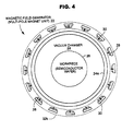
- Fig. 4 illustrates a first modification of the above-mentioned preferred embodiment of the present invention, wherein the magnetic members 30, which respectively carry no segment magnets 28, are removed or not installed. With this modification, it is possible to reduce the magnetic field strength in the vicinity of the inner wall 24a of the vacuum chamber 24.
- the inventor of the present invention conducted another experiment under the same conditions as mentioned above while the magnetic members 30 each having no segment magnet 28 are removed as shown in Fig. 4. The experimental result indicated that the magnetic flux density in the vicinity of the inner wall of the chamber 24 was able to be reduced to 0.023T (230G).
- Fig. 5 shows a second modification of the above-mentioned preferred embodiment, in which eight pairs of segment magnets 28 are arranged in a manner to be attached to the magnetic members 30 at intervals of two.
- This arrangement can be realized without difficulty by relocating the magnetic members 30 with and without the segment magnets 28.
- an eight-pole magnetic field is generated within the vacuum chamber 24, and the magnetic force lines extend further toward the center of the chamber 24 compared with the embodiment shown in Fig. 2. Accordingly, with this modification, the magnetic field strength can be increased in a space surrounding the workpiece 26 relative to the case shown in Fig. 2.
- the second modification it is possible to provide four groups of segment magnets 28 with each group consisting of four magnets 28 arranged in proximity with each other. In this case, four-pole magnetic field is generated. As the number of magnetic poles decreases, the magnetic fluxes extend further inside the vacuum chamber 24.
- the magnetic members 30, each of which accompanies the segment magnet as shown in Figs. 2, 4 and 5, are movably installed in the supporter 32a and 32b in an outward radial direction.
- the magnetic members 30 of Fig. 4 are movably installed in the supporter 32a and 32b in both outward and inward radial directions. It is understood that the radial displacement of the magnetic members 30 enables it possible to control the multi-pole magnetic field strength within the vacuum chamber 24.
- Fig. 6(A) schematically shows a combination of one magnetic member 30 and one segment magnet 28 before being moved in a radial direction, while Fig. 6(B) shows the combination has been radially displaced.
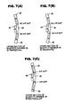
- each magnetic member 30 is desirably configured such as to have a trapezoidal or fan-shaped cross section in a direction perpendicular to the central axis of the magnetic field generator, as shown in Figs. 7(A) and 7(B).
- Figs. 7(C) the magnetic fluxes decreases due to magnetic saturation caused by air gaps with the result of undesirable reduction of the multi-pole magnetic field strength.
Landscapes
- Physics & Mathematics (AREA)
- Engineering & Computer Science (AREA)
- Plasma & Fusion (AREA)
- Chemical & Material Sciences (AREA)
- Analytical Chemistry (AREA)
- Electromagnetism (AREA)
- Spectroscopy & Molecular Physics (AREA)
- Plasma Technology (AREA)
- Drying Of Semiconductors (AREA)
- Physical Or Chemical Processes And Apparatus (AREA)
- Physical Vapour Deposition (AREA)
Abstract
Description
Claims (4)
- A magnetic field generator for generating a multi-pole magnetic field around a workpiece positioned within a vacuum chamber, the magnetic field generator being provided outside the vacuum chamber and comprising a plurality of segment type permanent magnets circularly arranged, characterized in that
the magnetic field generator comprises a plurality of magnetic members to which the segment magnets are selectively attached. - The magnetic field generator as claimed in claim 1, further comprising a ring-like supporter by which the magnetic members are detachably supported.
- The magnetic field generator as claimed in claim 1 to 2, each of the magnetic members has a trapezoidal or fan-shaped cross section in a direction perpendicular to the central axis of the magnetic field generator.
- The magnetic field generator as claimed in any of claims 1 to 3, wherein the magnetic members are respectively able to be displaced radially with respect to the central axis of the magnetic field generator.
Applications Claiming Priority (2)
| Application Number | Priority Date | Filing Date | Title |
|---|---|---|---|
| JP2002161348A JP3611324B2 (en) | 2002-06-03 | 2002-06-03 | Magnetron plasma magnetic field generator |
| JP2002161348 | 2002-06-03 |
Publications (3)
| Publication Number | Publication Date |
|---|---|
| EP1369898A2 true EP1369898A2 (en) | 2003-12-10 |
| EP1369898A3 EP1369898A3 (en) | 2005-09-14 |
| EP1369898B1 EP1369898B1 (en) | 2007-08-01 |
Family
ID=29545629
Family Applications (1)
| Application Number | Title | Priority Date | Filing Date |
|---|---|---|---|
| EP03012176A Expired - Lifetime EP1369898B1 (en) | 2002-06-03 | 2003-06-03 | Magnetic field generator for magnetron plasma |
Country Status (6)
| Country | Link |
|---|---|
| US (1) | US6765466B2 (en) |
| EP (1) | EP1369898B1 (en) |
| JP (1) | JP3611324B2 (en) |
| KR (2) | KR100742087B1 (en) |
| DE (1) | DE60315216T2 (en) |
| TW (1) | TWI276174B (en) |
Families Citing this family (25)
| Publication number | Priority date | Publication date | Assignee | Title |
|---|---|---|---|---|
| CA2706421A1 (en) * | 2007-11-27 | 2009-06-04 | Kim Shallcross | Method and apparatus for storing and applying magnetic fields |
| EP2251455B1 (en) | 2009-05-13 | 2017-09-06 | SiO2 Medical Products, Inc. | PECVD coating using an organosilicon precursor |
| US9458536B2 (en) | 2009-07-02 | 2016-10-04 | Sio2 Medical Products, Inc. | PECVD coating methods for capped syringes, cartridges and other articles |
| US11624115B2 (en) | 2010-05-12 | 2023-04-11 | Sio2 Medical Products, Inc. | Syringe with PECVD lubrication |
| US9878101B2 (en) | 2010-11-12 | 2018-01-30 | Sio2 Medical Products, Inc. | Cyclic olefin polymer vessels and vessel coating methods |
| US9272095B2 (en) | 2011-04-01 | 2016-03-01 | Sio2 Medical Products, Inc. | Vessels, contact surfaces, and coating and inspection apparatus and methods |
| CN103930595A (en) | 2011-11-11 | 2014-07-16 | Sio2医药产品公司 | Passivation, ph protective or lubricity coating for pharmaceutical package, coating process and apparatus |
| US11116695B2 (en) | 2011-11-11 | 2021-09-14 | Sio2 Medical Products, Inc. | Blood sample collection tube |
| CA2887352A1 (en) | 2012-05-09 | 2013-11-14 | Sio2 Medical Products, Inc. | Saccharide protective coating for pharmaceutical package |
| US20150297800A1 (en) | 2012-07-03 | 2015-10-22 | Sio2 Medical Products, Inc. | SiOx BARRIER FOR PHARMACEUTICAL PACKAGE AND COATING PROCESS |
| JP6509734B2 (en) | 2012-11-01 | 2019-05-08 | エスアイオーツー・メディカル・プロダクツ・インコーポレイテッド | Film inspection method |
| WO2014075163A1 (en) | 2012-11-15 | 2014-05-22 | James Andrew Leskosek | Plasma gate |
| US9903782B2 (en) | 2012-11-16 | 2018-02-27 | Sio2 Medical Products, Inc. | Method and apparatus for detecting rapid barrier coating integrity characteristics |
| US9764093B2 (en) | 2012-11-30 | 2017-09-19 | Sio2 Medical Products, Inc. | Controlling the uniformity of PECVD deposition |
| WO2014085348A2 (en) | 2012-11-30 | 2014-06-05 | Sio2 Medical Products, Inc. | Controlling the uniformity of pecvd deposition on medical syringes, cartridges, and the like |
| EP2961858B1 (en) | 2013-03-01 | 2022-09-07 | Si02 Medical Products, Inc. | Coated syringe. |
| US9937099B2 (en) | 2013-03-11 | 2018-04-10 | Sio2 Medical Products, Inc. | Trilayer coated pharmaceutical packaging with low oxygen transmission rate |
| CN105392916B (en) | 2013-03-11 | 2019-03-08 | Sio2医药产品公司 | Coated Packaging Materials |
| EP2971227B1 (en) | 2013-03-15 | 2017-11-15 | Si02 Medical Products, Inc. | Coating method. |
| US11066745B2 (en) | 2014-03-28 | 2021-07-20 | Sio2 Medical Products, Inc. | Antistatic coatings for plastic vessels |
| US11077233B2 (en) | 2015-08-18 | 2021-08-03 | Sio2 Medical Products, Inc. | Pharmaceutical and other packaging with low oxygen transmission rate |
| KR20170062185A (en) * | 2015-11-27 | 2017-06-07 | 한국전기연구원 | Apparatus of Forming Magnet Field in High Power Magnetron |
| DE102017101867A1 (en) | 2017-01-31 | 2018-08-02 | VON ARDENNE Asset GmbH & Co. KG | Magnetron assembly, controlled magnet system and method |
| CN109706432B (en) * | 2017-12-11 | 2021-04-06 | 绍兴市载沣智能科技有限公司 | Circular magnetic electrode device and wound surface modification equipment including the same |
| US12020965B2 (en) * | 2020-10-21 | 2024-06-25 | Applied Materials, Inc. | Magnetic holding structures for plasma processing applications |
Family Cites Families (7)
| Publication number | Priority date | Publication date | Assignee | Title |
|---|---|---|---|---|
| JPH03257159A (en) * | 1990-03-05 | 1991-11-15 | Shin Etsu Chem Co Ltd | Sputtering equipment using dipole ring type magnetic circuit |
| CA2052080C (en) * | 1990-10-10 | 1997-01-14 | Jesse N. Matossian | Plasma source arrangement for ion implantation |
| US5262028A (en) * | 1992-06-01 | 1993-11-16 | Sierra Applied Sciences, Inc. | Planar magnetron sputtering magnet assembly |
| JP3585578B2 (en) * | 1995-05-30 | 2004-11-04 | アネルバ株式会社 | Plasma processing equipment |
| JPH11509273A (en) * | 1995-07-10 | 1999-08-17 | シーヴィシー、プラダクツ、インク | Permanent magnet arrangement apparatus and method |
| US7067034B2 (en) * | 2000-03-27 | 2006-06-27 | Lam Research Corporation | Method and apparatus for plasma forming inner magnetic bucket to control a volume of a plasma |
| US20030010454A1 (en) * | 2000-03-27 | 2003-01-16 | Bailey Andrew D. | Method and apparatus for varying a magnetic field to control a volume of a plasma |
-
2002
- 2002-06-03 JP JP2002161348A patent/JP3611324B2/en not_active Expired - Fee Related
-
2003
- 2003-06-02 KR KR1020030035211A patent/KR100742087B1/en not_active Expired - Fee Related
- 2003-06-02 US US10/449,598 patent/US6765466B2/en not_active Expired - Lifetime
- 2003-06-02 TW TW092114930A patent/TWI276174B/en not_active IP Right Cessation
- 2003-06-03 DE DE60315216T patent/DE60315216T2/en not_active Expired - Lifetime
- 2003-06-03 EP EP03012176A patent/EP1369898B1/en not_active Expired - Lifetime
-
2007
- 2007-05-25 KR KR1020070050789A patent/KR100781030B1/en not_active Expired - Fee Related
Also Published As
| Publication number | Publication date |
|---|---|
| EP1369898B1 (en) | 2007-08-01 |
| US6765466B2 (en) | 2004-07-20 |
| DE60315216T2 (en) | 2007-11-22 |
| US20030222742A1 (en) | 2003-12-04 |
| DE60315216D1 (en) | 2007-09-13 |
| KR20070062959A (en) | 2007-06-18 |
| TW200402105A (en) | 2004-02-01 |
| KR20030094079A (en) | 2003-12-11 |
| KR100742087B1 (en) | 2007-07-23 |
| EP1369898A3 (en) | 2005-09-14 |
| JP2004014541A (en) | 2004-01-15 |
| JP3611324B2 (en) | 2005-01-19 |
| KR100781030B1 (en) | 2007-11-30 |
| TWI276174B (en) | 2007-03-11 |
Similar Documents
| Publication | Publication Date | Title |
|---|---|---|
| EP1369898B1 (en) | Magnetic field generator for magnetron plasma | |
| CA1255815A (en) | Semiconductor etching apparatus with magnetic array and vertical shield | |
| KR960002633B1 (en) | Magnetron cathode assembly | |
| EP0762471B1 (en) | Magnetic field generator for magnetron plasma | |
| JP4817592B2 (en) | Magnetron plasma magnetic field generator, plasma etching apparatus and method using the magnetic field generator | |
| US4943361A (en) | Plasma treating method and apparatus therefor | |
| JP3629305B2 (en) | Magnetron sputter cathode | |
| JP4090985B2 (en) | Magnetic field generator for multipole magnetron plasma | |
| JPH0660393B2 (en) | Plasma concentrated high-speed sputter device | |
| JP3766569B2 (en) | Magnetron sputtering equipment | |
| JPH028366A (en) | Magnetron sputtering device | |
| JP4123495B2 (en) | Magnetic field generator for magnetron plasma | |
| JP4489868B2 (en) | Cathode electrode apparatus and sputtering apparatus | |
| JPH11350130A5 (en) | ||
| JP4219925B2 (en) | Magnetron sputtering equipment | |
| JP3932886B2 (en) | Inductively coupled plasma generating apparatus and plasma processing apparatus | |
| JPS6250941B2 (en) | ||
| JPS6026094Y2 (en) | Discharge electrode device for plasma treatment | |
| JP5306425B6 (en) | Magnetic field generator for magnetron plasma | |
| JPS6026095Y2 (en) | Cooling device for plasma discharge electrode | |
| JP2006161062A (en) | Magnetron sputtering film forming apparatus and electrode structure thereof | |
| JPH0517870A (en) | Magnetron sputtering device | |
| JPS63241190A (en) | Single wafer plasma processing equipment | |
| JPH05271968A (en) | Plasma etching equipment | |
| JPH06136528A (en) | Magnetron sputtering equipment |
Legal Events
| Date | Code | Title | Description |
|---|---|---|---|
| PUAI | Public reference made under article 153(3) epc to a published international application that has entered the european phase |
Free format text: ORIGINAL CODE: 0009012 |
|
| AK | Designated contracting states |
Kind code of ref document: A2 Designated state(s): AT BE BG CH CY CZ DE DK EE ES FI FR GB GR HU IE IT LI LU MC NL PT RO SE SI SK TR |
|
| AX | Request for extension of the european patent |
Extension state: AL LT LV MK |
|
| PUAL | Search report despatched |
Free format text: ORIGINAL CODE: 0009013 |
|
| AK | Designated contracting states |
Kind code of ref document: A3 Designated state(s): AT BE BG CH CY CZ DE DK EE ES FI FR GB GR HU IE IT LI LU MC NL PT RO SE SI SK TR |
|
| AX | Request for extension of the european patent |
Extension state: AL LT LV MK |
|
| RIC1 | Information provided on ipc code assigned before grant |
Ipc: 7H 01J 37/32 A Ipc: 7H 01F 7/02 B |
|
| 17P | Request for examination filed |
Effective date: 20050831 |
|
| AKX | Designation fees paid |
Designated state(s): DE FR GB |
|
| R17C | First examination report despatched (corrected) |
Effective date: 20051026 |
|
| GRAP | Despatch of communication of intention to grant a patent |
Free format text: ORIGINAL CODE: EPIDOSNIGR1 |
|
| GRAS | Grant fee paid |
Free format text: ORIGINAL CODE: EPIDOSNIGR3 |
|
| GRAA | (expected) grant |
Free format text: ORIGINAL CODE: 0009210 |
|
| AK | Designated contracting states |
Kind code of ref document: B1 Designated state(s): DE FR GB |
|
| REG | Reference to a national code |
Ref country code: GB Ref legal event code: FG4D |
|
| REF | Corresponds to: |
Ref document number: 60315216 Country of ref document: DE Date of ref document: 20070913 Kind code of ref document: P |
|
| ET | Fr: translation filed | ||
| PLBE | No opposition filed within time limit |
Free format text: ORIGINAL CODE: 0009261 |
|
| STAA | Information on the status of an ep patent application or granted ep patent |
Free format text: STATUS: NO OPPOSITION FILED WITHIN TIME LIMIT |
|
| 26N | No opposition filed |
Effective date: 20080506 |
|
| REG | Reference to a national code |
Ref country code: FR Ref legal event code: PLFP Year of fee payment: 14 |
|
| REG | Reference to a national code |
Ref country code: FR Ref legal event code: PLFP Year of fee payment: 15 |
|
| REG | Reference to a national code |
Ref country code: FR Ref legal event code: PLFP Year of fee payment: 16 |
|
| PGFP | Annual fee paid to national office [announced via postgrant information from national office to epo] |
Ref country code: GB Payment date: 20190529 Year of fee payment: 17 |
|
| PGFP | Annual fee paid to national office [announced via postgrant information from national office to epo] |
Ref country code: DE Payment date: 20200519 Year of fee payment: 18 Ref country code: FR Payment date: 20200512 Year of fee payment: 18 |
|
| GBPC | Gb: european patent ceased through non-payment of renewal fee |
Effective date: 20200603 |
|
| PG25 | Lapsed in a contracting state [announced via postgrant information from national office to epo] |
Ref country code: GB Free format text: LAPSE BECAUSE OF NON-PAYMENT OF DUE FEES Effective date: 20200603 |
|
| REG | Reference to a national code |
Ref country code: DE Ref legal event code: R119 Ref document number: 60315216 Country of ref document: DE |
|
| PG25 | Lapsed in a contracting state [announced via postgrant information from national office to epo] |
Ref country code: DE Free format text: LAPSE BECAUSE OF NON-PAYMENT OF DUE FEES Effective date: 20220101 |
|
| PG25 | Lapsed in a contracting state [announced via postgrant information from national office to epo] |
Ref country code: FR Free format text: LAPSE BECAUSE OF NON-PAYMENT OF DUE FEES Effective date: 20210630 |