EP1369846A2 - Sprachsynthese - Google Patents
Sprachsynthese Download PDFInfo
- Publication number
- EP1369846A2 EP1369846A2 EP03253523A EP03253523A EP1369846A2 EP 1369846 A2 EP1369846 A2 EP 1369846A2 EP 03253523 A EP03253523 A EP 03253523A EP 03253523 A EP03253523 A EP 03253523A EP 1369846 A2 EP1369846 A2 EP 1369846A2
- Authority
- EP
- European Patent Office
- Prior art keywords
- waveform data
- speech
- filter
- correction filter
- speech waveform
- Prior art date
- Legal status (The legal status is an assumption and is not a legal conclusion. Google has not performed a legal analysis and makes no representation as to the accuracy of the status listed.)
- Granted
Links
- 238000012937 correction Methods 0.000 claims abstract description 194
- 238000001228 spectrum Methods 0.000 claims abstract description 172
- 238000000034 method Methods 0.000 claims abstract description 141
- 230000015572 biosynthetic process Effects 0.000 claims abstract description 135
- 238000003786 synthesis reaction Methods 0.000 claims abstract description 119
- 230000008569 process Effects 0.000 claims abstract description 107
- 238000004458 analytical method Methods 0.000 claims description 35
- 230000006870 function Effects 0.000 claims description 28
- 238000012545 processing Methods 0.000 claims description 15
- 230000008707 rearrangement Effects 0.000 claims description 10
- 230000008859 change Effects 0.000 claims description 7
- 238000001308 synthesis method Methods 0.000 claims description 6
- 230000004044 response Effects 0.000 claims description 4
- 238000000926 separation method Methods 0.000 claims 1
- 238000004364 calculation method Methods 0.000 description 13
- 238000013139 quantization Methods 0.000 description 12
- 239000013598 vector Substances 0.000 description 11
- 238000001914 filtration Methods 0.000 description 10
- 238000010586 diagram Methods 0.000 description 4
- 230000006866 deterioration Effects 0.000 description 3
- 230000002542 deteriorative effect Effects 0.000 description 3
- 230000000694 effects Effects 0.000 description 3
- 230000001360 synchronised effect Effects 0.000 description 3
- 230000002194 synthesizing effect Effects 0.000 description 3
- 238000005070 sampling Methods 0.000 description 2
- 238000007796 conventional method Methods 0.000 description 1
- 230000003247 decreasing effect Effects 0.000 description 1
- 230000007850 degeneration Effects 0.000 description 1
- 238000007429 general method Methods 0.000 description 1
- 230000003287 optical effect Effects 0.000 description 1
- 230000011218 segmentation Effects 0.000 description 1
Images


Classifications
-
- G—PHYSICS
- G10—MUSICAL INSTRUMENTS; ACOUSTICS
- G10L—SPEECH ANALYSIS TECHNIQUES OR SPEECH SYNTHESIS; SPEECH RECOGNITION; SPEECH OR VOICE PROCESSING TECHNIQUES; SPEECH OR AUDIO CODING OR DECODING
- G10L13/00—Speech synthesis; Text to speech systems
- G10L13/06—Elementary speech units used in speech synthesisers; Concatenation rules
-
- G—PHYSICS
- G10—MUSICAL INSTRUMENTS; ACOUSTICS
- G10L—SPEECH ANALYSIS TECHNIQUES OR SPEECH SYNTHESIS; SPEECH RECOGNITION; SPEECH OR VOICE PROCESSING TECHNIQUES; SPEECH OR AUDIO CODING OR DECODING
- G10L13/00—Speech synthesis; Text to speech systems
- G10L13/02—Methods for producing synthetic speech; Speech synthesisers
- G10L13/04—Details of speech synthesis systems, e.g. synthesiser structure or memory management
Definitions
- the present invention relates to a speech synthesis apparatus and method for synthesizing speech.
- a method of generating desired synthetic speech by segmenting each of speech segments which are recorded and stored in advance into a plurality of micro-segments, and re-arranging the micro-segments obtained as a result of segmentation is available.
- the micro-segments undergo processes such as interval change, repetition, skipping (thinning out), and the like, thus obtaining synthetic speech having a desired duration and fundamental frequency.
- Fig. 17 illustrates the method of segmenting a speech waveform into micro-segments.
- the speech waveform shown in Fig. 17 is segmented into micro-segments by a cutting window function (to be referred to as a window function hereinafter).
- a window function synchronized with the pitch interval of source speech is used for a voiced sound part (latter half of the speech waveform).
- a window function with an appropriate interval is used for an unvoiced sound part.
- the continuation duration of speech can be shortened.
- the continuation duration of speech can be extended.
- the fundamental frequency of synthetic speech can be increased.
- the fundamental frequency of synthetic speech can be decreased.
- units upon recording and storing speech segments units such as phonemes, or CV ⁇ VC or VCV are used.
- CV ⁇ VC is a unit in which the segment boundary is set in phonemes
- VCV is a unit in which the segment boundary is set in vowels.
- a speech synthesis method comprising:
- a speech synthesis apparatus which executes the aforementioned speech synthesis method, and a speech synthesis dictionary generation apparatus which executes the speech synthesis dictionary generation method are provided.
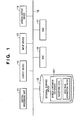
- Fig. 1 is a block diagram showing the hardware arrangement of the first embodiment.
- reference numeral 11 denotes a central processing unit, which executes processes such as numerical value operations, control, and the like. Especially, the central processing unit 11 executes a speech synthesis process according to a sequence to be described later.
- Reference numeral 12 denotes an output device which presents various kinds of information to the user under the control of the central processing unit 11.
- Reference numeral 13 denotes an input device which comprises a touch panel, keyboard, or the like, and is used by the user to give operation instructions and to input various kinds of information to this apparatus.
- Reference numeral 14 denotes a speech output device which outputs speech synthesis contents.
- Reference numeral 15 denotes a storage device such as a disk device, nonvolatile memory, or the like, which holds a speech synthesis dictionary 501 and the like.
- Reference numeral 16 denotes a read-only storage device which stores the sequence of a speech synthesis process of this embodiment, and required permanent data.
- Reference numeral 17 denotes a storage device such as a RAM or the like, which holds temporary information.
- the RAM 17 holds temporary data, various flags, and the like.
- the aforementioned building components (11 to 17) are connected via a bus 18.
- the ROM 16 stores a control program for the speech synthesis process, and the central processing unit 11 executes that program.
- control program may be stored in the external storage device 15, and may be loaded onto the RAM 17 upon execution of that program.
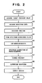
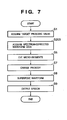
- Fig. 2 is a flow chart for explaining a speech output process according to the first embodiment.
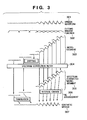
- Fig. 3 shows the speech synthesis state of the first embodiment.
- a target prosodic value of synthetic speech is acquired.
- the target prosodic value of synthetic speech may be directly given from a host module like in singing voice synthesis or may be estimated using some means.
- the target prosodic value of synthetic speech is estimated based on the linguistic analysis result of text.
- step S2 waveform data (speech waveform 301 in Fig. 3) as a source of synthetic speech is acquired.
- step S3 the acquired waveform data undergoes acoustic analysis such as linear prediction analysis, cepstrum analysis, generalized cepstrum analysis, or the like to calculate parameters required to form a spectrum correction filter 304. Note that analysis of waveform data may be done at given time intervals, or pitch synchronized analysis may be done.
- step S4 a spectrum correction filter is formed using the parameters calculated in step S3. For example, if linear prediction analysis of the p-th order is used as the acoustic analysis, a filter having characteristics given by: is used as the spectrum correction filter. When equation (1) is used, linear prediction coefficients ⁇ j are calculated in the parameter calculation.
- cepstrum coefficients c j are calculated in the parameter calculation.
- ⁇ and ⁇ are appropriate coefficients
- ⁇ is a linear prediction coefficient
- c is a cepstrum coefficient
- an FIR filter which is formed by windowing the impulse response of the above filter at an appropriate order and is given by: may be used.
- coefficients ⁇ j are calculated in the parameter calculation.
- step S5 a window function 302 is applied to the waveform acquired in step S2 to cut micro-segments 303.
- a window function 302 is applied to the waveform acquired in step S2 to cut micro-segments 303.
- the window function a Hanning window or the like is used.
- step S6 the filter 304 formed in step S4 is applied to micro-segments 303 cut in step S5, thereby correcting the spectrum of the micro-segments cut in step S5. In this way, spectrum-corrected micro-segments 305 are acquired.
- step S7 the micro-segments 305 that have undergone spectrum correction in step S6 undergo skipping, repetition, and interval change processes to match the target prosodic value acquired in step S1, and are then re-arranged (306).
- step S8 the micro-segments re-arranged in step S7 are superposed to obtain synthetic speech 307. Since speech obtained in step S8 is a speech segment, actual synthetic speech is obtained by concatenating a plurality of speech segments obtained in step S8. That is, in step S9 synthetic speech is output by concatenating speech segments obtained in step S8.
- skipping may be executed prior to application of the spectrum correction filter, as shown in Fig. 3.
- a wasteful process i.e., a filter process for micro-segments which are discarded upon skipping, can be omitted.
- the spectrum correction filter is formed upon speech synthesis.
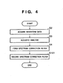
- the spectrum correction filter may be formed prior to speech synthesis, and formation information (filter coefficients) required to form the filter may be held in a predetermined storage area. That is, the process of the first embodiment can be separated into two processes, i.e., data generation (Fig. 4) and speech synthesis (Fig. 5). The second embodiment will explain processes in such case. Note that the apparatus arrangement required to implement the processes of this embodiment is the same as that in the first embodiment (Fig. 1). In this embodiment, formation information of a correction filter is stored in the speech synthesis dictionary 501.
- steps S2, S3, and S4 are the same as those in the first embodiment (Fig. 2).
- step S101 filter coefficients of a spectrum correction filter formed in step S4 are recorded in the external storage device 15.
- spectrum correction filters are formed in correspondence with respective waveform data registered in the speech synthesis dictionary 501, and coefficients of the filters corresponding to the respective waveform data are held in the speech synthesis dictionary 501. That is, the speech synthesis dictionary 501 of the second embodiment registers waveform data and spectrum correction filters of respective speech waveforms.
- step S102 load a spectrum correction filter
- step S102 spectrum correction filter coefficients recorded in step S101 in Fig. 4 are loaded. That is, coefficients of a spectrum correction filter corresponding to waveform data acquired in step S2 are loaded from the speech synthesis dictionary 501 to form the spectrum correction filter.
- step S6 a micro-segment process is executed using the spectrum correction filter loaded in step S102.
- a filter formed in step S4 (form a spectrum correction filter) is applied to micro-segments cut in step S5 (cut micro-segments).
- the spectrum correction filter may be applied to waveform data (speech waveform 301) acquired in step S2.
- the third embodiment will explain such speech synthesis process. Note that the apparatus arrangement required to implement the process of this embodiment is the same as that in the first embodiment (Fig. 1).
- Fig. 6 is a flow chart for explaining a speech synthesis process according to the third embodiment. Referring to Fig. 6, steps S2 to S4 are the same as those in the second embodiment.
- steps S2 to S4 are the same as those in the second embodiment.
- step S201 it is applied to waveform data acquired in step S2, thus correcting the spectrum of the waveform data in step S102.
- step S202 the waveform data that has undergone spectrum correction in step S201 is recorded. That is, in the third embodiment, the speech synthesis dictionary 501 in Fig. 1 stores "spectrum-corrected waveform data" in place of "spectrum correction filter". Note that speech waveform data may be corrected during the speech synthesis process without being registered in the speech synthesis dictionary. In this case, for example, waveform data read in step S2 in Fig. 2 is corrected using the spectrum correction filter formed in step S4, and the corrected waveform data can be used in step S5. In this case, step S6 can be omitted.
- step S203 is added in place of step S2 in the above embodiments.
- the spectrum-corrected waveform data recorded in step S202 is acquired as that from which micro-segments are to be cut in step S5.
- Micro-segments are cut from the acquired waveform data, and are re-arranged, thus obtaining spectrum-corrected synthetic speech. Since the spectrum-corrected waveform data is used, a spectrum correction process (step S6 in the first and second embodiments) for micro-segments can be omitted.
- the speech output process is separated into two processes, i.e., data generation and speech synthesis like in the second embodiment.
- filtering may be executed every time a synthesis process is executed like in the first embodiment.
- the spectrum correction filter is applied to waveform data, which is to undergo a synthesis process, between steps S4 and S5 in the flow chart shown in Fig. 2.
- step S6 can be omitted.
- the filter formed in step S4 is applied to micro-segments cut in step S5.
- the filter formed in step S4 is applied to waveform data before micro-segments are cut.
- the spectrum correction filter may be applied to waveform data of synthetic speech synthesized in step S8.
- the fourth embodiment will explain a process in such case. Note that the apparatus arrangement required to implement the process of this embodiment is the same as that in the first embodiment (Fig. 1).
- Fig. 8 is a flow chart for explaining a speech synthesis process according to the fourth embodiment.
- the same step numbers in Fig. 8 denote the same processes as those in the first embodiment (Fig. 2).
- step S301 is inserted after step S8, and step S6 is omitted, as shown in Fig. 8.
- step S301 the filter formed in step S4 is applied to waveform data of synthetic speech obtained in step S8, thus correcting its spectrum.
- the processing volume can be reduced compared to the first embodiment.
- the spectrum correction filter may be formed in advance as in the first and second embodiments. That is, filter coefficients are pre-stored in the speech synthesis dictionary 501, and are read out upon speech synthesis to form a spectrum correction filter, which is applied to waveform data that has undergone waveform superposition in step S8.
- the spectrum correction filter can be expressed as a synthetic filter of a plurality of partial filters, spectrum correction can be distributed to a plurality of steps in place of executing spectrum correction in one step in the first to fourth embodiments.
- spectrum correction can be distributed to a plurality of steps in place of executing spectrum correction in one step in the first to fourth embodiments.
- the fifth embodiment will explain a speech synthesis process to be implemented by distributing the spectrum correction filter. Note that the apparatus arrangement required to implement the process of this embodiment is the same as that in the first embodiment (Fig. 1).
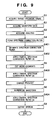
- Fig. 9 is a flow chart for explaining the speech synthesis process according to the fifth embodiment. As shown in Fig. 9, processes in steps S1 to S4 are executed first. These processes are the same as those in steps S1 to S4 in the first to fourth embodiments.
- step S401 the spectrum correction filter formed in step S4 is degenerated into two to three partial filters (element filters).
- F 1 (z) F 1,1 (z)F 1,2 (z)F 1,3 (z)
- equation (3) is factorized and is expressed as:
- cepstrum coefficients need only be grouped like:
- step S402 waveform data acquired in step S2 is filtered using one of the filters degenerated in step S401. That is, waveform data before micro-segments are cut undergoes a spectrum correction process using a first filter element as one of a plurality of filter elements obtained in step S401.
- step S5 a window function is applied to waveform data obtained as a result of partial application of the spectrum correction filter in step S402 to cut micro-segments.
- step S403 the micro-segments cut in step S5 undergo filtering using another one of the filters degenerated in step S401. That is, the cut micro-segments undergo a spectrum correction process using a second filter element as one of the plurality of filter elements obtained in step S401.
- step S404 synthetic speech obtained in step S8 undergoes filtering using still another one of the filters degenerated in step S401. That is, the waveform data of the obtained synthetic speech undergoes a spectrum correction process using a third filter element as one of the plurality of filter elements obtained in step S401.
- step S9 the synthetic speech obtained as a result of step S404 is output.
- F 1,1 (z), F 1,2 (z), and F 1,3 (z) can be respectively used in steps S402, S403, and S404.
- step S401 the filter is degenerated into two polynomials, i.e., denominator and numerator polynomials
- the spectrum correction filter or element filters may be registered in advance in the speech synthesis dictionary 501 as in the first and second embodiments.
- the spectrum correction filter coefficients may be recorded after they are quantized by, e.g., vector quantization or the like, in place of being directly recorded. In this way, the data size to be recorded on the external storage device 15 can be reduced.
- the quantization efficiency can be improved by converting filter coefficients into line spectrum pairs (LSPs) and then quantizing them.
- LSPs line spectrum pairs
- the waveform data may be split into bands using a band split filter, and each individual band-limited waveform may undergo spectrum correction filtering.
- band split the order of the spectrum correction filter can be suppressed, and the calculation volume can be reduced. The same effect is expected by expanding/compressing the frequency axis like mel-cepstrum.
- the timing of spectrum correction filtering has a plurality of choices.
- the timing of spectrum correction filtering and ON/OFF control of spectrum correction may be selected for respective segments.
- the phoneme type, voiced/unvoiced type, and the like may be used as information for selection.
- a formant emphasis filter that emphasizes the formant may be used.
- the first to fifth embodiments have explained the speech synthesis apparatus and method, which reduce "blur" of a speech spectrum by correcting the spectra of micro-segments by applying the spectrum correction filter to the micro-segments shown in Fig. 17.
- Such process can relax phenomena such a broadened formant of speech, unsharp top and bottom peaks of a spectrum envelope, and the like, which have occurred due to application of a window function to obtain micro-segments from a speech waveform, and can prevent the sound quality of synthetic speech from deteriorating.
- a corresponding spectrum filter 304 is applied to each of micro-segments 303 which are cut from a speech waveform 301 by a window function 302, thus obtaining spectrum-corrected micro-segments 305 (e.g., formant-corrected micro-segments). Then, synthetic speech 307 is generated using the spectrum-corrected micro-segments 305.
- the spectrum correction filter is obtained by acoustic analysis.
- the following three filters are listed:
- the filter order p or FIR filter order p' is reduced, the calculation volume and storage size can be reduced.
- the storage size required to hold the spectrum correction filter coefficients can be reduced.
- the spectrum correction effect is reduced, and the sound quality deteriorates.
- "blur" of a speech spectrum is reduced and speech synthesis with high sound quality is realized, while suppressing increases in calculation volume and storage size by reducing those required for spectrum correction filtering.
- the sixth embodiment reduces the calculation volume and storage size using an approximate filter with a smaller filter order, and waveform data in the speech synthesis dictionary is modified to be suited to the approximate filter, thus maintaining the high quality of synthetic speech.
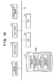
- Fig. 10 is a block diagram showing the hardware arrangement in the sixth embodiment.
- the same reference numerals in Fig. 10 denote the same parts as those in Fig. 1 explained in the first embodiment.
- the external storage device 15 holds a speech synthesis dictionary 502 and the like.
- the speech synthesis dictionary 502 stores modified waveform data generated by modifying a speech waveform by a method to be described later, and a spectrum correction filter formed by approximation using a method to be described later.
- Figs. 11 and 12 are flow charts for explaining a speech output process according to the sixth embodiment.
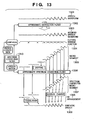
- Fig. 13 shows the speech synthesis process state according to the sixth embodiment.
- a spectrum correction filter is formed prior to speech synthesis, and formation information (filter coefficients) required to form the filter is held in a predetermined storage area (speech synthesis dictionary) as in the second embodiment. That is, the speech output process of the sixth embodiment is divided into two processes, i.e., a data generation process (Fig. 11) for generating a speech synthesis dictionary, and a speech synthesis process (Fig. 12).
- a data generation process Fig. 11
- a speech synthesis process Fig. 12
- the information size of formation information is reduced by adopting approximation of a spectrum correction filter, and each speech waveform in the speech synthesis dictionary is modified to prevent deterioration of synthetic speech due to approximation of the spectrum correction filter.
- step S21 waveform data (speech waveform 1301 in Fig. 13) as a source of synthetic speech is acquired.
- step S22 the waveform data acquired in step S21 undergoes acoustic analysis such as linear prediction analysis, cepstrum analysis, generalized cepstrum analysis, or the like to calculate parameters required to form a spectrum correction filter 1310. Note that analysis of waveform data may be done at given time intervals, or pitch synchronized analysis may be done.
- a spectrum correction filter 1310 is formed using the parameters calculated in step S22. For example, if linear prediction analysis of the p-th order is used as the acoustic analysis, a filter having characteristics given by equation (1) is used as the spectrum correction filter 1310. If cepstrum analysis of the p-th order is used, a filter having characteristics given by equation (2) is used as the spectrum correction filter 1310. Alternatively, an FIR filter which is formed by windowing the impulse response of the above filter at an appropriate order and is given by equation (3) can be used as the spectrum correction filter 1310. In practice, the above equations must consider the system gains.
- step S24 the spectrum correction filter 1310 formed in step S23 is simplified by approximation to form an approximate spectrum correction filter 1306, which can be implemented by a smaller calculation volume and storage size.
- an approximate spectrum correction filter 1306 a filter obtained by limiting the windowing order of the FIR filter expressed by equation (3) to a low order may be used.
- the frequency characteristic difference from the spectrum correction filter may be defined as a distance on a spectrum domain, and filter coefficients that minimize the difference may be calculated by, e.g., a Newton method or the like to form the approximate correction filter.
- step S25 the approximate spectrum correction filter 1306 formed in step 24 is recorded in the speech synthesis dictionary 502 (in practice, approximate spectrum correction filter coefficients are stored).
- steps S26 to S28 speech waveform data is modified so as to reduce deterioration of sound quality upon applying the approximate spectrum correction filter which is formed and recorded in the speech synthesis dictionary 502 in steps S24 and S25, and the modified speech waveform data is registered in the speech synthesis dictionary 502.
- step S26 the spectrum correction filter 1310 and an inverse filter of the approximate spectrum correction filter 1306 are synthesized to form an approximate correction filter 1302.
- the approximate correction filter is given by:
- step S27 the approximate correction filter 1302 is applied to the speech waveform data acquired in step S21 to generate a modified speech waveform 1303.
- step S28 the modified speech waveform obtained in step S27 is recorded in the speech synthesis dictionary 502.
- the data generation process has been explained.
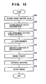
- the speech synthesis process will be described below with reference to the flow chart of Fig. 12.
- the approximate spectrum correction filter 1306 and modified speech waveform 1303, which have been registered in the speech synthesis dictionary 502 by the above data generation process, are used.
- a target prosodic value of synthetic speech is acquired.
- the target prosodic value of synthetic speech may be directly given from a host module like in singing voice synthesis or may be estimated using some means.
- the target prosodic value of synthetic speech is estimated based on a language analysis result of text.
- step S30 the modified speech waveform recorded in the speech synthesis dictionary 502 is acquired on the basis of the target prosodic value acquired in step S39.
- step S31 the approximate spectrum correction filter recorded in the speech synthesis dictionary 502 in step S25 is loaded. Note that the approximate spectrum correction filter to be loaded is the one which corresponds to the modified speech waveform acquired in step S30.
- step S32 a window function 1304 is applied to the modified speech waveform acquired in step S30 to cut micro-segments 1305.
- window function a Hanning window or the like is used.
- step S33 the approximate spectrum correction filter 1306 loaded in step S31 is applied to each of the micro-segments 1305 cut in step S32 to correct the spectrum of each micro-segment 1305. In this way, spectrum-corrected micro-segments 1307 are acquired.
- step S34 the micro-segments 1307 that have undergone spectrum correction in step S33 undergo skipping, repetition, and interval change processes to match the target prosodic value acquired in step S29, and are then re-arranged (1308), thereby changing a prosody.
- step S35 the micro-segments re-arranged in step S34 are superposed to obtain synthetic speech (speech segment) 1309.
- step S36 synthetic speech is output by concatenating the synthetic speech (speech segments) 1309 obtained in step S35.
- "skipping" may be executed prior to application of the approximate spectrum correction filter 1306, as shown in Fig. 13. In this way, a wasteful process, i.e., a filter process applied to micro-segments which may be skipped, can be omitted.
- the sixth embodiment has explained the example wherein the order of filter coefficients is reduced by approximation to reduce the calculation volume and storage size.
- the seventh embodiment will explain a case wherein the storage size is reduced by clustering spectrum correction filters.
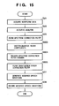
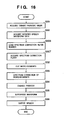
- the seventh embodiment is implemented by three processes, i.e., a clustering process (Fig. 14), data generation process (Fig. 15), and speech synthesis process (Fig. 16). Note that the apparatus arrangement required to implement the processes of this embodiment is the same as that in the sixth embodiment (Fig. 10).
- steps S21, S22, and S23 are processes for forming a spectrum correction filter, and are the same as those in the sixth embodiment (Fig. 11). These processes are executed for all waveform data included in the speech synthesis dictionary 502 (step S600).
- step S601 After spectrum correction filters of all the waveform data are formed, the flow advances to step S601 to cluster the spectrum correction filters obtained in step S23.
- clustering for example, a method called an LBG algorithm or the like can be applied.
- step S602 the clustering result (clustering information) in step S601 is recorded in the external storage device 15. More specifically, a correspondence table between representative vectors (filter coefficients) of respective clusters and cluster numbers is generated and recorded. Based on this representative vector, a spectrum correction filter (representative filter) of the corresponding cluster is formed.
- spectrum correction filters are formed in correspondence with respective waveform data registered in the speech synthesis dictionary 502 in step S23, and spectrum correction filter coefficients corresponding to respective waveform data are held in the speech synthesis dictionary 502 as the cluster numbers. That is, as will be described later using Fig. 15, the speech synthesis dictionary 502 of the seventh embodiment registers the waveform data of respective speech waveforms (strictly speaking, modified speech waveform data (to be described later using Fig. 15)), the cluster numbers and representative vectors (representative values of respective coefficients) of spectrum correction filters.
- a dictionary generation process (Fig. 15) will be described below.
- the spectrum filter formation processes in steps S21 to S23 are the same as those in the sixth embodiment.
- filter coefficients of each spectrum correction filter are vector-quantized and are registered as a cluster number. That is, in step S603 a vector closest to a spectrum correction filter obtained in step S23 is selected from representative vectors of clustering information recorded in step S602. A number (cluster number) corresponding to the representative vector selected in step S603 is recorded in the speech synthesis dictionary 502 in step S604.
- a modified speech waveform is generated to suppress deterioration of synthetic speech due to quantization of the filter coefficients of the spectrum correction filter, and is registered in the speech synthesis dictionary. That is, in step S605 a quantization error correction filter used to correct quantization errors is formed.
- the quantization error correction filter is formed by synthesizing an inverse filter of the filter formed using the representative vector, and a spectrum correction filter of the corresponding speech waveform. For example, when the filter given by equation (1) is used as the spectrum correction filter, the quantization error correction filter is given by: where ⁇ ' is the vector-quantized linear prediction coefficient. When filters of other formats are used, quantization error correction filters can be similarly formed.
- Waveform data is modified using the quantization error correction filter formed in this way to generate a modified speech waveform (step S27), and the obtained modified speech waveform is registered in the speech synthesis dictionary 502 (step S28). Since each spectrum correction filter is registered using the cluster number and correspondence table (cluster information), the storage size required for the speech synthesis dictionary can be reduced.
- step S31 the step of loading an approximate spectrum correction filter
- step S606 a process for loading the spectrum correction filter number (cluster number)
- step S607 a process for acquiring a spectrum correction filter based on the loaded cluster number
- a target prosodic value is acquired (step S29), and the modified speech waveform data registered in step S28 in Fig. 15 is acquired (step S30).
- the spectrum correction filter number recorded in step S604 is loaded.
- a spectrum correction filter corresponding to the spectrum correction filter number is acquired on the basis of the correspondence table recorded in step S602.
- synthetic speech is output by processes in steps S32 to S36 as in the sixth embodiment. More specifically, micro-segments are cut by applying a window function to the modified speech waveform (step S32).
- the spectrum correction filter acquired in step S607 is applied to the cut micro-segments to acquire spectrum-corrected micro-segments (step S33).
- the spectrum-corrected micro-segments are re-arranged in accordance with the target prosodic value (step S34), and the re-arranged micro-segments are superposed to obtain synthetic speech (speech segment) 1309 (step S35).
- the waveform data when the sampling frequency of waveform data is high, the waveform data may be split into bands using a band split filter, and each individual band-limited waveform may undergo spectrum correction filtering.
- filters are formed for respective bands, a speech waveform itself to be processed undergoes band split, and the processes are executed for respective split waveforms.
- band split the order of the spectrum correction filter can be suppressed, and the calculation volume can be reduced. The same effect is expected by expanding/compressing the frequency axis like mel-cepstrum.
- an embodiment that combines the sixth and seventh embodiments is available.
- a filter based on a representative vector may be approximated, or coefficients of an approximate spectrum correction filter may be vector-quantized.
- an acoustic analysis result may be temporarily converted, and a converted vector may be vector-quantized.
- the linear prediction coefficients are converted into LSP coefficients, and these LSP coefficients are quantized in place of directly vector-quantizing the linear prediction coefficients.
- linear prediction coefficients obtained by inversely converting the quantized LSP coefficients can be used. In general, since the LSP coefficients have better quantization characteristics than the linear prediction coefficients, more approximate vector quantization can be made.
- the calculation volume and storage size required to execute processes for reducing "blur" of a speech spectrum due to a window function applied to obtain micro-segments can be reduced, and speech synthesis with high sound quality can be realized by limited computer resources.
- the objects of the present invention are also achieved by supplying a storage medium, which records a program code of a software program that can implement the functions of the above-mentioned embodiments to the system or apparatus, and reading out and executing the program code stored in the storage medium by a computer (or a CPU or MPU) of the system or apparatus.
- the program code itself read out from the storage medium implements the functions of the above-mentioned embodiments, and the storage medium which stores the program code constitutes the present invention.
- the storage medium for supplying the program code for example, a flexible disk, hard disk, optical disk, magneto-optical disk, CD-ROM, CD-R, magnetic tape, nonvolatile memory card, ROM, and the like may be used.
- the functions of the above-mentioned embodiments may be implemented not only by executing the readout program code by the computer but also by some or all of actual processing operations executed by an OS (operating system) running on the computer on the basis of an instruction of the program code.
- OS operating system
- the functions of the above-mentioned embodiments may be implemented by some or all of actual processing operations executed by a CPU or the like arranged in a function extension board or a function extension unit, which is inserted in or connected to the computer, after the program code read out from the storage medium is written in a memory of the extension board or unit.
Landscapes
- Engineering & Computer Science (AREA)
- Computational Linguistics (AREA)
- Health & Medical Sciences (AREA)
- Audiology, Speech & Language Pathology (AREA)
- Human Computer Interaction (AREA)
- Physics & Mathematics (AREA)
- Acoustics & Sound (AREA)
- Multimedia (AREA)
- Compression, Expansion, Code Conversion, And Decoders (AREA)
- Electrophonic Musical Instruments (AREA)
Applications Claiming Priority (4)
| Application Number | Priority Date | Filing Date | Title |
|---|---|---|---|
| JP2002164624A JP4332323B2 (ja) | 2002-06-05 | 2002-06-05 | 音声合成方法および装置並びに辞書生成方法および装置 |
| JP2002164624 | 2002-06-05 | ||
| JP2002208340 | 2002-07-17 | ||
| JP2002208340A JP3897654B2 (ja) | 2002-07-17 | 2002-07-17 | 音声合成方法および装置 |
Publications (3)
| Publication Number | Publication Date |
|---|---|
| EP1369846A2 true EP1369846A2 (de) | 2003-12-10 |
| EP1369846A3 EP1369846A3 (de) | 2005-04-06 |
| EP1369846B1 EP1369846B1 (de) | 2010-06-16 |
Family
ID=29552390
Family Applications (1)
| Application Number | Title | Priority Date | Filing Date |
|---|---|---|---|
| EP03253523A Expired - Lifetime EP1369846B1 (de) | 2002-06-05 | 2003-06-04 | Sprachsynthese |
Country Status (3)
| Country | Link |
|---|---|
| US (1) | US7546241B2 (de) |
| EP (1) | EP1369846B1 (de) |
| DE (1) | DE60332980D1 (de) |
Families Citing this family (9)
| Publication number | Priority date | Publication date | Assignee | Title |
|---|---|---|---|---|
| JP2003295882A (ja) | 2002-04-02 | 2003-10-15 | Canon Inc | 音声合成用テキスト構造、音声合成方法、音声合成装置及びそのコンピュータ・プログラム |
| JP4280505B2 (ja) | 2003-01-20 | 2009-06-17 | キヤノン株式会社 | 情報処理装置及び情報処理方法 |
| US20080177548A1 (en) * | 2005-05-31 | 2008-07-24 | Canon Kabushiki Kaisha | Speech Synthesis Method and Apparatus |
| US20070124148A1 (en) * | 2005-11-28 | 2007-05-31 | Canon Kabushiki Kaisha | Speech processing apparatus and speech processing method |
| JP2008225254A (ja) * | 2007-03-14 | 2008-09-25 | Canon Inc | 音声合成装置及び方法並びにプログラム |
| US8027835B2 (en) * | 2007-07-11 | 2011-09-27 | Canon Kabushiki Kaisha | Speech processing apparatus having a speech synthesis unit that performs speech synthesis while selectively changing recorded-speech-playback and text-to-speech and method |
| JP2013003470A (ja) * | 2011-06-20 | 2013-01-07 | Toshiba Corp | 音声処理装置、音声処理方法および音声処理方法により作成されたフィルタ |
| JP6127371B2 (ja) * | 2012-03-28 | 2017-05-17 | ヤマハ株式会社 | 音声合成装置および音声合成方法 |
| WO2014112206A1 (ja) * | 2013-01-15 | 2014-07-24 | ソニー株式会社 | 記憶制御装置、再生制御装置および記録媒体 |
Citations (1)
| Publication number | Priority date | Publication date | Assignee | Title |
|---|---|---|---|---|
| EP0984425A2 (de) | 1998-08-31 | 2000-03-08 | Canon Kabushiki Kaisha | Verfahren und Vorrichtung zur Sprachsynthese |
Family Cites Families (23)
| Publication number | Priority date | Publication date | Assignee | Title |
|---|---|---|---|---|
| JPS61172200A (ja) | 1985-01-25 | 1986-08-02 | 松下電工株式会社 | 音声合成装置 |
| FR2636163B1 (fr) * | 1988-09-02 | 1991-07-05 | Hamon Christian | Procede et dispositif de synthese de la parole par addition-recouvrement de formes d'onde |
| JP2588004B2 (ja) | 1988-09-19 | 1997-03-05 | 日本電信電話株式会社 | 後処理フィルタ |
| JPH02247700A (ja) | 1989-03-20 | 1990-10-03 | Ricoh Co Ltd | 音声合成装置 |
| US5278943A (en) * | 1990-03-23 | 1994-01-11 | Bright Star Technology, Inc. | Speech animation and inflection system |
| US5642466A (en) * | 1993-01-21 | 1997-06-24 | Apple Computer, Inc. | Intonation adjustment in text-to-speech systems |
| JPH0784993A (ja) | 1993-09-17 | 1995-03-31 | Fujitsu Ltd | 信号抑圧装置 |
| JPH07152787A (ja) | 1994-01-13 | 1995-06-16 | Sony Corp | 情報アクセスシステムおよび記録媒体 |
| JP3548230B2 (ja) * | 1994-05-30 | 2004-07-28 | キヤノン株式会社 | 音声合成方法及び装置 |
| JP3559588B2 (ja) * | 1994-05-30 | 2004-09-02 | キヤノン株式会社 | 音声合成方法及び装置 |
| JP3319556B2 (ja) | 1995-09-14 | 2002-09-03 | 株式会社東芝 | ホルマント強調方法 |
| US6240384B1 (en) * | 1995-12-04 | 2001-05-29 | Kabushiki Kaisha Toshiba | Speech synthesis method |
| JPH09230896A (ja) | 1996-02-28 | 1997-09-05 | Sony Corp | 音声合成装置 |
| JP3281281B2 (ja) | 1996-03-12 | 2002-05-13 | 株式会社東芝 | 音声合成方法及び装置 |
| JPH1195796A (ja) | 1997-09-16 | 1999-04-09 | Toshiba Corp | 音声合成方法 |
| JP3263015B2 (ja) | 1997-10-02 | 2002-03-04 | 株式会社エヌ・ティ・ティ・データ | 音声素片接続方法及び音声合成装置 |
| JPH11109992A (ja) | 1997-10-02 | 1999-04-23 | Oki Electric Ind Co Ltd | 音声素片データベースの作成方法、音声合成方法、音声素片データベース、音声素片データベース作成装置および音声合成装置 |
| US6144939A (en) * | 1998-11-25 | 2000-11-07 | Matsushita Electric Industrial Co., Ltd. | Formant-based speech synthesizer employing demi-syllable concatenation with independent cross fade in the filter parameter and source domains |
| JP2001117573A (ja) | 1999-10-20 | 2001-04-27 | Toshiba Corp | 音声スペクトル強調方法/装置及び音声復号化装置 |
| JP3949346B2 (ja) | 2000-03-31 | 2007-07-25 | 株式会社東芝 | 音声合成方法及び装置 |
| JP4054507B2 (ja) * | 2000-03-31 | 2008-02-27 | キヤノン株式会社 | 音声情報処理方法および装置および記憶媒体 |
| JP2001282278A (ja) * | 2000-03-31 | 2001-10-12 | Canon Inc | 音声情報処理装置及びその方法と記憶媒体 |
| JP3728172B2 (ja) * | 2000-03-31 | 2005-12-21 | キヤノン株式会社 | 音声合成方法および装置 |
-
2003
- 2003-06-02 US US10/449,072 patent/US7546241B2/en not_active Expired - Fee Related
- 2003-06-04 EP EP03253523A patent/EP1369846B1/de not_active Expired - Lifetime
- 2003-06-04 DE DE60332980T patent/DE60332980D1/de not_active Expired - Lifetime
Patent Citations (1)
| Publication number | Priority date | Publication date | Assignee | Title |
|---|---|---|---|---|
| EP0984425A2 (de) | 1998-08-31 | 2000-03-08 | Canon Kabushiki Kaisha | Verfahren und Vorrichtung zur Sprachsynthese |
Non-Patent Citations (1)
| Title |
|---|
| NOE, NOISE REDUCTION FOR NOISE ROBUST FEATURE EXTRACTION FOR DISTRIBUTED SPEECH RECOGNITION |
Also Published As
| Publication number | Publication date |
|---|---|
| EP1369846A3 (de) | 2005-04-06 |
| US20030229496A1 (en) | 2003-12-11 |
| DE60332980D1 (de) | 2010-07-29 |
| US7546241B2 (en) | 2009-06-09 |
| EP1369846B1 (de) | 2010-06-16 |
Similar Documents
| Publication | Publication Date | Title |
|---|---|---|
| EP1308928B1 (de) | System und Verfahren zur Sprachsynthese unter Verwendung eines Glattungsfilters | |
| US7856357B2 (en) | Speech synthesis method, speech synthesis system, and speech synthesis program | |
| EP0458859B1 (de) | System und methode zur text-sprache-umsetzung mit hilfe von kontextabhängigen vokalallophonen | |
| US9275631B2 (en) | Speech synthesis system, speech synthesis program product, and speech synthesis method | |
| JP5159325B2 (ja) | 音声処理装置及びそのプログラム | |
| JPH10171484A (ja) | 音声合成方法および装置 | |
| US7792672B2 (en) | Method and system for the quick conversion of a voice signal | |
| US20090112580A1 (en) | Speech processing apparatus and method of speech processing | |
| EP1369846B1 (de) | Sprachsynthese | |
| JP3450237B2 (ja) | 音声合成装置および方法 | |
| US6178402B1 (en) | Method, apparatus and system for generating acoustic parameters in a text-to-speech system using a neural network | |
| US7765103B2 (en) | Rule based speech synthesis method and apparatus | |
| US6594631B1 (en) | Method for forming phoneme data and voice synthesizing apparatus utilizing a linear predictive coding distortion | |
| JP2600384B2 (ja) | 音声合成方法 | |
| JP2017167526A (ja) | 統計的パラメトリック音声合成のためのマルチストリームスペクトル表現 | |
| JP5075865B2 (ja) | 音声処理装置、方法、及びプログラム | |
| JP4332323B2 (ja) | 音声合成方法および装置並びに辞書生成方法および装置 | |
| JP3444396B2 (ja) | 音声合成方法、その装置及びプログラム記録媒体 | |
| JP3897654B2 (ja) | 音声合成方法および装置 | |
| JP5106274B2 (ja) | 音声処理装置、音声処理方法及びプログラム | |
| JPH1195796A (ja) | 音声合成方法 | |
| JPH09230893A (ja) | 規則音声合成方法及び音声合成装置 | |
| JP2007052456A (ja) | 音声合成用辞書生成方法及び装置 | |
| JPH08160991A (ja) | 音声素片作成方法および音声合成方法、装置 | |
| JP2000035797A (ja) | 音声認識装置 |
Legal Events
| Date | Code | Title | Description |
|---|---|---|---|
| PUAI | Public reference made under article 153(3) epc to a published international application that has entered the european phase |
Free format text: ORIGINAL CODE: 0009012 |
|
| AK | Designated contracting states |
Kind code of ref document: A2 Designated state(s): AT BE BG CH CY CZ DE DK EE ES FI FR GB GR HU IE IT LI LU MC NL PT RO SE SI SK TR |
|
| AX | Request for extension of the european patent |
Extension state: AL LT LV MK |
|
| PUAL | Search report despatched |
Free format text: ORIGINAL CODE: 0009013 |
|
| AK | Designated contracting states |
Kind code of ref document: A3 Designated state(s): AT BE BG CH CY CZ DE DK EE ES FI FR GB GR HU IE IT LI LU MC NL PT RO SE SI SK TR |
|
| AX | Request for extension of the european patent |
Extension state: AL LT LV MK |
|
| 17P | Request for examination filed |
Effective date: 20050823 |
|
| AKX | Designation fees paid |
Designated state(s): DE FR GB |
|
| 17Q | First examination report despatched |
Effective date: 20051007 |
|
| GRAP | Despatch of communication of intention to grant a patent |
Free format text: ORIGINAL CODE: EPIDOSNIGR1 |
|
| GRAS | Grant fee paid |
Free format text: ORIGINAL CODE: EPIDOSNIGR3 |
|
| GRAA | (expected) grant |
Free format text: ORIGINAL CODE: 0009210 |
|
| AK | Designated contracting states |
Kind code of ref document: B1 Designated state(s): DE FR GB |
|
| REF | Corresponds to: |
Ref document number: 60332980 Country of ref document: DE Date of ref document: 20100729 Kind code of ref document: P |
|
| PLBE | No opposition filed within time limit |
Free format text: ORIGINAL CODE: 0009261 |
|
| STAA | Information on the status of an ep patent application or granted ep patent |
Free format text: STATUS: NO OPPOSITION FILED WITHIN TIME LIMIT |
|
| 26N | No opposition filed |
Effective date: 20110317 |
|
| REG | Reference to a national code |
Ref country code: DE Ref legal event code: R097 Ref document number: 60332980 Country of ref document: DE Effective date: 20110316 |
|
| REG | Reference to a national code |
Ref country code: FR Ref legal event code: PLFP Year of fee payment: 13 |
|
| PGFP | Annual fee paid to national office [announced via postgrant information from national office to epo] |
Ref country code: GB Payment date: 20150626 Year of fee payment: 13 Ref country code: DE Payment date: 20150630 Year of fee payment: 13 |
|
| PGFP | Annual fee paid to national office [announced via postgrant information from national office to epo] |
Ref country code: FR Payment date: 20150626 Year of fee payment: 13 |
|
| REG | Reference to a national code |
Ref country code: DE Ref legal event code: R119 Ref document number: 60332980 Country of ref document: DE |
|
| GBPC | Gb: european patent ceased through non-payment of renewal fee |
Effective date: 20160604 |
|
| REG | Reference to a national code |
Ref country code: FR Ref legal event code: ST Effective date: 20170228 |
|
| PG25 | Lapsed in a contracting state [announced via postgrant information from national office to epo] |
Ref country code: DE Free format text: LAPSE BECAUSE OF NON-PAYMENT OF DUE FEES Effective date: 20170103 Ref country code: FR Free format text: LAPSE BECAUSE OF NON-PAYMENT OF DUE FEES Effective date: 20160630 |
|
| PG25 | Lapsed in a contracting state [announced via postgrant information from national office to epo] |
Ref country code: GB Free format text: LAPSE BECAUSE OF NON-PAYMENT OF DUE FEES Effective date: 20160604 |