EP1369683A1 - Humidity sensor element and method for manufacture thereof - Google Patents
Humidity sensor element and method for manufacture thereof Download PDFInfo
- Publication number
- EP1369683A1 EP1369683A1 EP02703961A EP02703961A EP1369683A1 EP 1369683 A1 EP1369683 A1 EP 1369683A1 EP 02703961 A EP02703961 A EP 02703961A EP 02703961 A EP02703961 A EP 02703961A EP 1369683 A1 EP1369683 A1 EP 1369683A1
- Authority
- EP
- European Patent Office
- Prior art keywords
- monomer
- humidity sensor
- sensor device
- group
- humidity
- Prior art date
- Legal status (The legal status is an assumption and is not a legal conclusion. Google has not performed a legal analysis and makes no representation as to the accuracy of the status listed.)
- Ceased
Links
- 0 CCC*C(C(C)CC)C(CC)C(C(C)*C)C1C(CC2C(C)C2)CCC1 Chemical compound CCC*C(C(C)CC)C(CC)C(C(C)*C)C1C(CC2C(C)C2)CCC1 0.000 description 4
Images







Classifications
-
- G—PHYSICS
- G01—MEASURING; TESTING
- G01N—INVESTIGATING OR ANALYSING MATERIALS BY DETERMINING THEIR CHEMICAL OR PHYSICAL PROPERTIES
- G01N27/00—Investigating or analysing materials by the use of electric, electrochemical, or magnetic means
- G01N27/02—Investigating or analysing materials by the use of electric, electrochemical, or magnetic means by investigating impedance
- G01N27/04—Investigating or analysing materials by the use of electric, electrochemical, or magnetic means by investigating impedance by investigating resistance
- G01N27/12—Investigating or analysing materials by the use of electric, electrochemical, or magnetic means by investigating impedance by investigating resistance of a solid body in dependence upon absorption of a fluid; of a solid body in dependence upon reaction with a fluid, for detecting components in the fluid
- G01N27/121—Investigating or analysing materials by the use of electric, electrochemical, or magnetic means by investigating impedance by investigating resistance of a solid body in dependence upon absorption of a fluid; of a solid body in dependence upon reaction with a fluid, for detecting components in the fluid for determining moisture content, e.g. humidity, of the fluid
-
- G—PHYSICS
- G01—MEASURING; TESTING
- G01N—INVESTIGATING OR ANALYSING MATERIALS BY DETERMINING THEIR CHEMICAL OR PHYSICAL PROPERTIES
- G01N27/00—Investigating or analysing materials by the use of electric, electrochemical, or magnetic means
- G01N27/02—Investigating or analysing materials by the use of electric, electrochemical, or magnetic means by investigating impedance
- G01N27/04—Investigating or analysing materials by the use of electric, electrochemical, or magnetic means by investigating impedance by investigating resistance
- G01N27/12—Investigating or analysing materials by the use of electric, electrochemical, or magnetic means by investigating impedance by investigating resistance of a solid body in dependence upon absorption of a fluid; of a solid body in dependence upon reaction with a fluid, for detecting components in the fluid
- G01N27/125—Composition of the body, e.g. the composition of its sensitive layer
- G01N27/126—Composition of the body, e.g. the composition of its sensitive layer comprising organic polymers
Definitions
- This invention relates to a humidity sensor device for detecting and determining moisture in the surrounding atmosphere and a method for preparing the same.
- Known humidity sensors designed to detect humidity through changes of electrical properties, typically electric resistance include those using electrolytes such as lithium chloride, metal oxides, and organic polymers as the humidity sensitive material.
- the humidity sensors using electrolytes such as lithium chloride can measure only a narrow range of humidity and are less resistant to water in that their performance can be altered by dew condensation and wetting.
- the humidity sensors using metal oxides are resistant to water, but low sensitive. Because of the lack of long-term stability when used alone, they undesirably require a heat cleaning circuit which would add to the operating cost and make the sensor structure complex.
- organic polymers especially polymeric electrolytes having quaternary ammonium salt have been widely used in commercial and industrial applications and so appreciated.
- JP-B Japanese Patent Publication
- JP-B No. 61-54176 discloses a humidity sensitive material comprising aggregates of latex particles formed of a copolymer between a hydrophobic monomer and an ionic or non-ionic hydrophilic monomer and having a hydrophilic surface layer.
- cationic compounds having primary to quaternary ammonium salts.
- JP-B 62-7976 discloses a humidity sensitive material in the form of a polymer which is obtained by polymerizing a compound containing 2-hydroxy-3-methacryloxypropyltrimethylammonium chloride to a degree of polymerization of 1,000 to 10,000.
- JP-B 2-24465 discloses the use as a humidity sensitive polymeric thin film of a thin film of an ionene polymer having the structural formula: -(N + (R 1 )(R 2 )X - -A-N + (R 3 )(R 4 )X - -B) n - wherein R 1 to R 4 are alkyl, X - is a halide ion, A and B each are -(CH 2 ) m - wherein m ⁇ 2, or a thin film of a mixture of the polymer with another polymer such as polyvinyl pyrrolidone for the purposes of improving substrate adhesion and water resistance.
- Humidity sensors using the polymeric electrolytes exemplified above as the humidity sensitive material are still low in water resistance in that the polymeric electrolytes can be partially leached in a high humidity region, especially in a dew condensing atmosphere. They also suffer from a hysteresis phenomenon that they produce different outputs at the same humidity depending on whether the humidity is increasing or decreasing. In a low humidity region having a relative humidity (RH) of less than 10%, they have so high resistance values that practical humidity measurement is impossible.
- RH relative humidity
- JP-A 7-318526 discloses that water resistance is improved by introducing an unsaturated bond into the ionene polymer at either end and crosslinking with ultraviolet radiation.
- a very thin film provides satisfactory properties and water resistance.
- the small thickness means so small an absolute amount of the polymer that the film is vulnerable to a gas which is dissolved in water to form ions (e.g., Cl 2 , NOx, SOx). The problem is serious particularly in a commercial application.
- the conductivity of a film having a thickness above a certain level is not substantially altered even when gas-origin ions are created in the surface layer.
- the polymer layer obtained by the above crosslinking method undergoes substantial swell upon absorption of water, giving rise to serious problems of crack generation and separation from the substrate. Under such circumstances, the film must be used at a thickness of no more than 1 ⁇ m.
- a primary object of the present invention is to provide a humidity sensor device having a humidity sensitive thin film which is resistant to water, maintains effective, stable performance over a long time even in a dew condensing atmosphere, is resistant to solvents and less vulnerable to gases such as nitrogen oxides, sulfur oxide and chlorine, and produces accurate outputs in a stable manner over a wide humidity region, especially in a low humidity region; and a method for preparing the same.
- Another object is to provide a simple method for preparing such a humidity sensor device having improved properties as mentioned above.
- a humidity sensitive thin film of an electrically conductive polymer is formed so as to cover a pair of opposed electrodes on an insulating substrate.
- the humidity sensitive thin film is obtained by furnishing at least one of crosslinking monomers of formula (1) (abbreviated as monomer of formula (1), hereinafter) and at least one of crosslinking monomers of formula (2) (abbreviated as monomer of formula (2), hereinafter), that is, at least two monomers together, and causing the monomers to polymerize together by suitable means such as ultraviolet irradiation or heating.
- the copolymer obtained therefrom is characterized by the possession of an ionene polymer structure having a quaternary ammonium salt (inclusive of cyclized one).
- the crosslinking copolymer undergoes three-dimensional reaction to form a crosslinked structure which becomes insoluble in water.
- the quaternary ammonium salt moiety contained in the copolymer molecule contributes to electric conductivity and the counter ion thereto is dissociated with moisture in the surrounding atmosphere to develop ionic conduction.
- Humidity is detected by utilizing the phenomenon that the degree of dissociation varies as the moisture content in the atmosphere increases or decreases.
- the copolymer is close to the backbone type with a less degree of freedom unlike the so-called pendant type. Its humidity response does not develop hysteresis.
- the humidity sensitive film which is formed by copolymerization of monomers on the electrodes does not always have a uniform distribution of crosslinking sites within it because polymerization takes place in a dry state. This is because, when copolymerization is effected by exposure to UV radiation, for example, the difference of photon density between the surface and the interior of the film becomes large in the case of solids, with the tendency that an outer side has a higher crosslinking density.
- the humidity sensitive film is more likely to crack upon swelling due to water absorption as it becomes thicker. It is then necessary to make the crosslinking density uniform or to increase the number of crosslinking sites.
- the first embodiment of the invention is characterized in that the monomer of formula (1) which can assume an ionene polymer structure having improved properties when polymerized to form a humidity sensitive material is combined as the crosslinking agent with the monomer of formula (2), for thereby increasing the number of crosslinking sites while maintaining a low impedance. Since the monomer of formula (1) and the monomer of formula (2), which differ in molecular weight, are analogous monomers in that they can possess an ionene polymer structure within them, they enable to increase the number of crosslinking sites without reducing the ion density.
- the factor of greater interest can be selected among basic factors of the humidity sensor including water resistance, gas resistance and hysteresis, which enables free design.
- An increase of ion density improves gas resistance
- an increase of crosslinking density improves water resistance.
- the monomer of formula (2) becomes more flexible, which restrains cracking after swelling. It is noted that to ensure water resistance in this case, the content of the monomer of formula (1) must be increased to enhance the degree of crosslinking.
- extreme crosslinking increases the possibility of hysteresis, which necessitates appropriate adjustment.
- the structural factors that dictate the conductivity of the crosslinking copolymer include the number of carbon atoms in the backbone of A and B in formula (2) and A 11 in formula (1) (i.e., the length of divalent linking group), the type of anions X 1 - and X 2 - in formula (2), and X 11 - and X 12 - in formula (1). Therefore, a sensor device having desired properties can also be designed by combining the monomers in which these parameters are suitable selected.
- JP-B 2-24465 cited above discloses a polymer containing a quaternary ammonium salt in its backbone, which is similar to the polymer according to the first embodiment of the invention. Unlike the first embodiment of the invention, the formation of a crosslinking structure within the polymer is referred to nowhere. In this respect, the first embodiment of the present invention is clearly different in construction and features from the patent publication. Although the combined use of another polymer such as polyvinyl pyrrolidone for the purpose of improving water resistance is recommended in the patent publication, the water resistance is apparently inferior.
- a methacryloxypropyl trimethyl ammonium salt having a hydroxyl group and trimethylolpropane trimethacrylate are applied to form a coating, after which the coating is polymerized and insolubilized for allegedly improving water resistance.
- What is disclosed is a method of mixing two or more polymers, followed by polymerization. Since the ammonium group on the humidity sensitive material is the so-called pendant type, the humidity response develops substantial hysteresis.
- the humidity sensitive thin film contains a crosslinking copolymer of a monomer of formula (1) with an acrylic monomer having an alkoxysilyl group. Then the humidity sensitive thin film is joined to the insulating substrate through reaction with the silane coupling agent within the molecule. That is, the humidity sensitive thin film is obtained by coating an aqueous solution or organic solvent solution of the monomer and the silane coupling agent having an acrylic unsaturated bond, drying, and subjecting the monomer and the silane coupling agent to copolymerization and crosslinking by irradiation of UV radiation and/or heating.
- the copolymer is characterized by having an ionene polymer structure having a quaternary ammonium salt (including cyclized one) as seen from the monomer of formula (1) and the silane coupling agent within the molecule.
- the quaternary ammonium salt moiety contained in the copolymer molecule contributes to electric conductivity and the counter ion thereto is dissociated with moisture in the surrounding atmosphere to develop ionic conduction. Humidity is detected by utilizing the phenomenon that the degree of dissociation varies as the moisture content in the atmosphere increases or decreases.
- the copolymer is close to the backbone type with a less degree of freedom unlike the so-called pendant type. Its humidity response does not develop hysteresis.
- the ion density and crosslinking degree of the humidity sensitive film can be controlled by adjusting the length of divalent linking group A 11 .
- An increase of ion density improves gas resistance
- an increase of crosslinking density improves water resistance.
- extreme crosslinking increases the possibility of hysteresis.
- the crosslinking copolymer undergoes three-dimensional reaction to form a crosslinked structure which becomes insoluble in water. Since the silane coupling agent structure is included within the molecule, the copolymer can be firmly joined to the substrate through covalent bonds by reacting with functional groups such as hydroxyl groups on the substrate surface and/or electrode surface. These bonds ensure that the humidity sensitive thin film remains water resistant without becoming loose or peeling even when it is thick.
- the humidity sensor has improved water resistance and gas resistance as well as improved solvent resistance.
- a low humidity region of RH 10% or lower can be measured, substantially spreading the measurable humidity region.
- the humidity sensor of the invention can measure humidity over the entire range from RH 0% to RH 100%, which was unmeasurable with conventional sensors.
- JP-B 2-24465 cited above discloses a polymer containing a quaternary ammonium salt in its backbone, which is similar to the polymer according to the second embodiment of the invention. Unlike the present invention, the structure having the silane coupling agent incorporated within the polymer and the crosslinking structure are referred to nowhere. Therefore, the second embodiment of the present invention is clearly different in construction and features from the patent publication. Although the combined use of another polymer such as polyvinyl pyrrolidone for the purpose of improving water resistance is recommended in the patent publication, the water resistance is apparently inferior.
- JP-A 4-258750 intends to improve water resistance by using an acrylic polymer having a cationic radical and a hydroxyl group and a polyfunctional isocyanate compound to form a three-dimensionally crosslinked polymer. With this method, it is expected that some of isocyanate is joined to the substrate surface by reacting with hydroxyl groups on the substrate surface, but its effect is little.
- a methacryloxypropyl trimethyl ammonium salt having a hydroxyl group and trimethylolpropane trimethacrylate are applied to form a coating, after which the coating is polymerized and insolubilized for allegedly improving water resistance.
- this fails to achieve a substantial improvement in the adhesion to the substrate.
- JP-A 7-318525 discloses a bonding method involving treating a substrate with silicon tetrachloride, and reacting with poly(2-hydroxy-3-methacryloxypropyl) trimethyl ammonium salt for thereby reacting the substrate surface with hydroxyl groups in the polymer.
- This method establishes the adhesion of the humidity sensitive film to the substrate, but encounters difficulty in reproducing substrate treating conditions because of the high reactivity and storage instability of silicon tetrachloride.
- the ammonium group of the humidity sensitive material is of the so-called pendant type, it is unavoidable that humidity response develops hysteresis.
- the humidity sensitive thin film is comprised of a polymer obtained from a monomer of formula (1), obviating the use of a monomer of formula (2) and an acrylic monomer having an alkoxysilyl group.
- the insulating substrate on which the humidity sensitive film is to be formed is, most often, an alumina substrate whose uppermost surface layer is covered with contaminants, adsorbed gases, organic matter and oxides of the substrate itself, which preclude the humidity sensitive film from adhering thereto.
- the removal of contaminants improves the adhesion of the humidity sensitive thin film to the insulating substrate.
- treatment by physical means is that treatment by chemical means, which can remove contaminants and organic matter, is not preferable because of difficulty to remove the oxide layer and the problem of used solution at the end of chemical treatment.
- the treatment by physical means can remove contaminants and oxides in a relatively simple manner while minimizing damage to the underlay.
- the material which is treated by physical means may be selected from a wide variety.
- plasma surface treatment is highly effective and preferable.
- the plasma surface treatment (to be referred to as "plasma treatment,” hereinafter) means that active electrons, radicals, ions and molecules in a plasma interact with the insulating substrate surface to exert etching and implantation effects for thereby modifying the surface state.
- the plasma to be generated varies with the plasma generating atmosphere and is generally divided into oxygen plasma and hydrogen plasma depending on the gas species used. Use of both oxygen plasma and hydrogen plasma is preferred. Oxygen plasma is effective for removal of surface organic contaminants and surface modification, and hydrogen plasma is able to reduce metal oxides.
- contaminants and oxides on the uppermost surface layer serve as a weak "boundary layer" at the interface between the humidity sensitive thin film and the insulating substrate.
- the adhesion is strengthened by removal of this boundary layer.
- the removal of contaminants and/or oxides on the uppermost surface layer renders the insulating substrate surface more wettable so that upon application of the humidity sensitive thin film-forming monomer, the monomer can reach and penetrate into pores in the insulating substrate, and after polymerization, the humidity sensitive thin film is bound and rooted to the insulating substrate to provide the "anchor" effect of tightly bonding the humidity sensitive thin film to the insulating substrate.
- the method of the invention according to the third embodiment wherein contaminants and/or oxides on the uppermost surface layer of the insulating substrate are removed by physical means before a humidity sensitive thin film is formed is applicable to not only the humidity sensitive thin film which is comprised of a polymer obtained from a monomer of formula (1), but also the humidity sensitive thin film which is comprised of a polymer obtained from a monomer having an ethylenically unsaturated reactive group, preferably a monomer having an ethylenically unsaturated reactive group and a quaternary ammonium salt. In either case, the adhesion between the humidity sensitive thin film and the insulating substrate is improved.
- the quaternary ammonium salts include, in a narrow sense, quaternary ammonium salts which are ammonium salts having four alkyl groups bonded to a nitrogen atom and, in a broad sense, ammonium type salts resulting from primary to tertiary amines.
- the humidity sensor device of the invention includes an insulating substrate, a pair of opposed electrodes disposed on the substrate to define a gap therebetween, and a humidity sensitive thin film lying on the gap.
- the humidity sensitive thin film is comprised of a copolymer of a monomer of formula (1) with a monomer of formula (2).
- a 11 is a divalent group.
- R 11 , R 12 , R 13 and R 14 each are an alkyl group and they may be the same or different.
- Y 11 and Y 12 each are a monovalent group terminated with an ethylenically unsaturated reactive group, and they may be the same or different. Any two or more of R 11 to R 14 , Y 11 , Y 12 , A 11 and portions thereof adjoining the nitrogen (N) atom may bond together to form a ring with the nitrogen (N) atom.
- X 11 - and X 12 - each are an anion and they may be the same or different.
- the divalent group represented by A 11 is preferably an alkylene, alkenylene or arylene group or a mixture thereof. These groups may have substituents, for example, alkyl groups such as methyl, and carbamoyl groups.
- the alkylene groups preferably have 1 to 20 carbon atoms in total.
- the alkenylene groups preferably have 2 to 10 carbon atoms in total.
- the arylene groups preferably have 6 to 20 carbon atoms in total.
- the divalent group is a mixture of these groups, the mixture preferably has 3 to 20 carbon atoms in total.
- a 11 is preferably an unsubstituted straight alkylene group wherein m is preferably about 3 to about 16 although m is determined depending on X 11 - , X 12 - or the type and copolymerization ratio of the monomer of formula (2) to be copolymerized therewith.
- the monovalent groups terminated with an ethylenically unsaturated reactive group represented by Y 11 and Y 12 are preferably acrylic, for example, groups having an acryloyloxyalkyl, methacryloyloxyalkyl, acryloylaminoalkyl and methacryloylaminoalkyl group, and preferably alkylene acrylate or methacrylate groups or alkylene acrylate or methacrylate amide groups.
- the total number of carbon atoms in Y 11 or Y 12 is preferably 4 to 8.
- Y 11 and Y 12 are generally the same, but may be different from each other.
- the alkyl groups represented by R 11 to R 14 are generally unsubstituted ones, but may have substituents, and preferably contain 1 to 5 carbon atoms in total. Examples include methyl, ethyl and propyl, with methyl being especially preferred. R 11 to R 14 are generally the same, but may be different from each other.
- R 11 to R 14 , Y 11 , Y 12 , A 11 and portions thereof adjoining the nitrogen (N) atom, taken together, may form a ring with the nitrogen (N) atom although it is preferred that they do not form a ring.
- the anions represented by X 11 - and X 12 - are preferably halide ions, for example, chloride, bromide and iodide ions. Chloride and bromide ions are preferred, and chloride ions are most preferred.
- X 11 - and X 12 - are generally the same, but may be different from each other.
- the monomer of formula (1) is preferably a difunctional monomer having an acrylic unsaturated reactive group at either end.
- the monomer of formula (1) used herein is obtained as follows. Illustratively, the monomer of formula (1) is synthesized according to the following scheme.
- Y 11 , Y 12 , R 11 to R 14 , and A 11 in the above scheme are as defined for formula (1).
- acrylic amine compounds (a-1, a-2) are reacted with a dihalogen compound (b) to form a monomer of formula (1) containing a quaternary ammonium salt and having an acrylic unsaturated group at either end.
- the amount of acrylic amine compounds added is at least 2 moles, especially 2.0 to 3.0 moles per mole of the dihalogen compound.
- the reaction is carried out by stirring the reactants in an aprotic polar solvent such as acetonitrile or dioxane at about 50°C for several days. If the reactants are subject to reflux in an alcohol such as methanol, isopropanol, methoxyethanol or 2-ethoxyethanol as the solvent, ester interchange can occur, failing to produce the desired diacrylic quaternary ammonium salt. Therefore, the alcoholic solvents which can trigger ester interchange reaction are not suitable.
- an aprotic polar solvent such as acetonitrile or dioxane
- the compounds used in introducing ethylenically unsaturated reactive groups, preferably acrylic unsaturated reactive groups into the monomer of formula (1) at both ends thereof are not critical as long as they have ethylenically unsaturated reactive groups, preferably acrylic unsaturated reactive groups such as acryloyloxy, methacryloyloxy, acryloylamino, methacryloylamino, diacryloylamino, and dimethacryloylamino groups.
- the preferred compounds are dialkylaminoethyl acrylates or methacrylates and dialkylaminoethyl acrylate or methacrylate amides. Illustrative examples are given below:
- dihalogen compounds to be reacted therewith examples include 1,3-dichloropropane, 1,4-dichlorobutane, 1,5-dichloropentane, 1,6-dichlorohexane, 1,8-dichlorooctane, 1,10-dichlorodecane, 1,12-dichlorododecane, 1,3-dibromopropane, 1,4-dibromobutane, 1,5-dibromopentane, 1,6-dibromohexane, 1,8-dibromooctane, 1,10-dibromodecane, and 1,12-dibromododecane.
- the molecular weight of the monomer of formula (1) is not critical although it is generally 650 or lower when the preferred A 11 or the like is taken into account.
- the lower limit is not critical although it is generally about 370.
- Y 1 to Y 6 each are a monovalent group, and at least one of Y 1 to Y 6 is a group terminated with an ethylenically unsaturated reactive group.
- exemplary groups include acryloyloxy, methacryloyloxy, acryloylamino, methacryloylamino, vinyl, allyl, diallylmethyl, allyloxy, diacryloylamino and dimethacryloylamino groups as well as groups having the foregoing groups introduced therein.
- Examples of the groups, other than the group terminated with an ethylenically unsaturated reactive group, represented by Y 1 to Y 6 include alkyl groups, alkenyl groups and halogen atoms.
- Examples of the alkyl and alkenyl groups are as exemplified for R 1 or the like in formulae (3) and (4) which are preferred among formula (2), and will be described later in conjunction with formulae (3) and (4).
- the halogen atoms include chlorine, bromine, iodine, etc. Any two or more of Y 1 to Y 5 , A and portions thereof, or any two or more of Y 4 to Y 6 , B and portions thereof, taken together, may form a ring with the nitrogen (N) atom.
- the ring thus formed is the same as the ring formed by R 1 or the like in formulae (3) and (4), and will be described later.
- the monomer of formula (2) may have at least one ethylenically unsaturated reactive group and most often, preferably about two such groups.
- the monovalent groups represented by Y 2 to Y 5 each may contain a chain for linking recurring units in the molecular structure represented by formula (2) and in this case, the recurring units in formula (2) may be the same or different.
- monomers of formula (2) monomers of formulae (3) and (4) are preferred.
- Formulae (3) and (4) are described below.
- a and B each are a divalent group.
- the divalent group represented by A is preferably an alkylene, alkenylene or arylene group or a mixture thereof. These groups may have substituents, for example, hydroxyl groups, alkyl groups such as methyl, and carbamoyl groups.
- the alkylene groups preferably have 1 to 20 carbon atoms in total and if substituted, they preferably have 1 to 5 hydroxyl groups.
- the alkenylene groups preferably have 2 to 10 carbon atoms in total.
- the arylene groups preferably have 6 to 20 carbon atoms in total.
- the divalent group is a mixture of these groups, the mixture preferably has 3 to 20 carbon atoms in total.
- A is preferably an unsubstituted alkylene group, especially straight -(CH 2 ) m - wherein m is preferably about 3 to about 16 although m is determined depending on B, X 1 - , X 2 - or the type and copolymerization ratio of the monomer of formula (1) to be copolymerized therewith.
- the divalent groups represented by B include alkylene groups, alkylene groups which are separated by at least one of oxy (-O-) and carbonyl (-CO-), alkenylene groups, arylene groups, and mixtures thereof, which may be substituted with hydroxyl groups or alkenyl groups such as vinyl.
- the alkylene groups preferably have 1 to 20 carbon atoms in total and if substituted, they preferably have 1 to 5 hydroxyl groups. When alkylene groups are separated by -O- and/or -CO-, the preferred number of such intervening groups is 1 to 5 in total.
- the alkenylene groups preferably have 2 to 10 carbon atoms in total.
- the arylene groups preferably have 6 to 20 carbon atoms in total.
- the divalent group is a mixture of these groups, the mixture preferably has 3 to 20 carbon atoms in total.
- B is preferably an unsubstituted alkylene group, especially straight -(CH 2 ) m - wherein m is preferably about 3 to about 16 although m is determined depending on A, X 1 - , X 2 - or the type and copolymerization ratio of the monomer of formula (1) to be copolymerized therewith.
- R 1 , R 2 , R 3 and R 4 is an alkyl or alkenyl group.
- the alkyl groups represented by R 1 to R 4 are preferably those of 1 to 10 carbon atoms, and may have substituents, but are preferably unsubstituted. Preferred examples include methyl, ethyl, propyl and butyl.
- the alkenyl groups represented by R 1 to R 4 are preferably those of 2 to 10 carbon atoms, and may have substituents, but are preferably unsubstituted.
- Preferred examples include vinyl, allyl, propenyl and butenyl.
- R 1 and R 2 , R 1 and A or a portion of A, R 2 and A or a portion of A, R 3 and R 4 , R 3 and A or a portion of A, R 4 and A or a portion of A, R 1 and R 3 or R 4 , or R 2 and R 3 or R 4 , taken together, may form a ring with the nitrogen (N) atom.
- These rings are preferably 5- or 6-membered rings, especially 6-membered nitrogenous heterocycles and may even bridged rings.
- Preferred examples of the nitrogenous heterocycles include pyridine, 1,4-azabicyclo[2.2.2]octane, piperidine, piperazine and pyrazine rings, which may be substituted with carbamoyl or other groups.
- R 5 and R 6 each are an alkyl or alkenyl group. Of these, alkyl groups are preferred, with those of 1 to 10 carbon atoms being especially preferred. The alkyl groups may have substituents, but are preferably unsubstituted. Methyl and ethyl are preferred groups. Examples of the alkenyl groups represented by R 5 and R 6 are as exemplified for R 1 to R 4 .
- L is a divalent group.
- Preferred examples of L in formula (3) include -COO(CH 2 ) 2 -, -CONH(CH 2 ) 3 -, and -(CH 2 ) m - wherein m is an integer of 1 to 20.
- Preferred examples of L in formula (4) include -OCH 2 CH 2 -, -(CH 2 ) m - wherein m is an integer of 1 to 20, -COO(CH 2 ) 2 -, -COOCH 2 CH(OH)CH 2 -, and -CH 2 -C 6 H 4 - (p- or m-form).
- any two or three of R 5 , R 6 and L, suitably taken together, may form a pyridine or analogous ring with the nitrogen (N) atom.
- R is hydrogen or an alkyl group, and preferably hydrogen or methyl.
- X 1 - and X 2 - are anions, preferably halide ions, for example, chloride, bromide and iodide ions, with chloride and bromide ions being preferred.
- X 1 - and X 2 - are generally the same, but may be different from each other.
- X 3 - is an anion.
- Illustrative examples and preferred examples of X 3 - are the same as those of X 1 - and X 2 - . Most often, X 1 - , X 2 - and X 3 - are the same.
- the letter n is a number of 2 to 5,000.
- the monomers of formulae (2), (3) and (4) are regarded as polymers comprising specific recurring units and having a number average molecular weight Mn of about 1,000 to about 1,000,000.
- the monomer of formula (3) can be synthesized according to the scheme shown below. Reference is made to the example wherein X 1 - and X 2 - are halide ions. The symbols used in the scheme are as defined previously.
- a diamine compound is reacted with a dihalogen compound to form an intermediate polymer I having a quaternary ammonium salt and terminal groups which are halogen.
- reaction may be carried out under such conditions that 1.0 to 2.0 moles of the dihalogen compound is available per mole of the diamine compound.
- the dihalogen compound may be added in two divided portions. It is recommended herein that the first portion of the dihalogen compound be 1 to 1.3 moles per mole of the diamine compound, and the balance be added as the second portion.
- the reaction is carried out in a nonaqueous solvent such as methanol, isopropanol, methoxyethanol or 2-ethoxyethanol at a reflux temperature or a temperature of about 100°C for about 5 to about 100 hours.
- a nonaqueous solvent such as methanol, isopropanol, methoxyethanol or 2-ethoxyethanol
- a compound having an ethylenically unsaturated reactive group, A is reacted with the intermediate polymer I for introducing ethylenically unsaturated reactive groups into the intermediate polymer I at both ends, to thereby form the monomer of formula (3).
- the reaction of this stage may be carried out subsequent to the reaction of the preceding stage.
- the compound having an ethylenically unsaturated reactive group, A in a substantially equimolar amount to the dihalogen compound, is added to the reaction solution whereupon reaction is carried out at a temperature of about 15 to about 100°C for about 10 to about 150 hours.
- reaction solution is added dropwise to a solvent such as acetone or ethyl acetate whereupon a precipitate forms.
- a solvent such as acetone or ethyl acetate
- the monomer of formula (4) can be synthesized according to the scheme shown below.
- the symbols used in the scheme are as defined previously. It is preferred that X 3 - be a halide ion as well.
- a diamine compound is reacted with a dihalogen compound to form an intermediate polymer II having a quaternary ammonium salt and terminal groups which are amino groups.
- reaction may be carried out under such conditions that 1.1 to 2.0 moles of the diamine compound is available per mole of the dihalogen compound.
- Reaction conditions other than this are the same as used above in the formation of intermediate polymer I. The same means as above may be taken to ensure that the terminal groups be amino groups.
- a compound having an ethylenically unsaturated reactive group, B is reacted with the intermediate polymer II for introducing ethylenically unsaturated reactive groups into the intermediate polymer II at both ends, to thereby form the monomer of formula (4).
- the reaction of this stage may be carried out in the same manner as used for the monomer of formula (3).
- the monomer of formula (3) or (4) is obtained by reaction of a diamine compound with a dihalogen compound. Any desired diamine compound and dihalogen compound may be used herein as long as they can follow the reaction according to the above scheme. It is noted that the monomers and intermediate polymers are typically obtained as a mixture of oligomers having a degree of polymerization (n) of about 2 to 20 and polymers having a degree of polymerization (n) of more than 20.
- X is a halogen atom, with chlorine and bromine atoms being preferred.
- the compounds A and B used in introducing ethylenically unsaturated reactive groups into intermediate polymers I and II at both ends are not critical as long as they have an ethylenically unsaturated reactive group such as an acryloyloxy, methacryloyloxy, acryloylamino, methacryloylamino, vinyl, allyl, diallylmethyl, allyloxy, diacryloylamino, and dimethacryloylamino group.
- intermediate polymers I and II as produced already have an ethylenically unsaturated reactive group at an end as in the case of, for example, polymers (10), (11) and (13), they may be used as the monomer in the practice of the invention without further reaction.
- X is a halogen atom, and preferably chlorine and bromine.
- the copolymer according to the first embodiment of the invention is obtained by applying a mixed solution of the monomer of formula (1), the monomer of formula (2) and a photo-polymerization initiator onto a substrate to form a coating, drying and irradiating UV radiation for polymerization.
- a mixed solution of the monomer of formula (1), the monomer of formula (2) and a photo-polymerization initiator onto a substrate to form a coating, drying and irradiating UV radiation for polymerization.
- a photo-polymerization initiator for each monomer type, one or more monomers may be used.
- the mixing ratio of the monomer of formula (1) to the monomer of formula (2) is determined in accordance with the intrinsic impedance of each monomer, the degree of crosslinking upon mixing, and the shape of electrodes on the substrate. Therefore, the mixing ratio differs case by case and is not determined within a certain range.
- the molar ratio of the monomer of formula (1) to the monomer of formula (2) is from about 10:1 to about 1:10.
- polymerization initiator any of commercially available polymerization initiators such as benzophenone derivatives may be used.
- polymerization is preferably carried out by irradiation of UV radiation although polymerization may also be induced by heating and preferably by heating followed by UV irradiation.
- the humidity sensitive thin film obtained by copolymerization reaction of quaternary ammonium salt monomers of formulae (1) and (2), preferably difunctional ammonium salts is not only very robust due to three-dimensional crosslinking, but also the quaternary ammonium salt has an ionene structure of the so-called backbone type and does not have a structure with a high degree of freedom like the pendant type structure. Therefore, the film maintains a humidity sensitive curve with minimal hysteresis.
- the humidity sensitive thin film according to the first embodiment of the invention contains a crosslinked product of the copolymer resulting from reaction of the monomer of formula (1) with the monomer of formula (2) as indicated above, formation of the humidity sensitive thin film is preferably carried out by the following procedure.
- a coating solution containing the monomer of formula (1) and the monomer of formula (2) is prepared.
- one monomer of formula (1) and one monomer of formula (2) are used in most cases although two or more different monomers may be used for each type or for either one of the two types.
- the monomers used herein are preferably those having a halide ion as the anion, more preferably a chloride or bromide ion. It is especially preferred to use at least one monomer having a chloride ion.
- the coating solution is an aqueous solution or an alcoholic or organic solvent solution or a mixture thereof which contains the monomers in a predetermined ratio and in a concentration of 1 to 10% by weight.
- a photo-polymerization initiator e.g., water-soluble benzophenone compound
- a concentration of 0.03 to 0.7% by weight is preferably added in a concentration of 0.03 to 0.7% by weight.
- the humidity sensitive thin film obtained according to the first embodiment of the invention does not peel from the substrate because the swell of the film is reduced as compared with conventional films, the following treatment may be further carried out in order to ensure the adhesion to the substrate and provide higher water resistance.
- An acrylic silane coupling agent which is an acrylic monomer having a functional group (alkoxysilyl group) capable of reacting with the substrate or electrode, such as ⁇ -methacryloxypropyltrimethoxysilane is copolymerized.
- the substrate usually electrode-bearing substrate
- an acrylic silane coupling agent is treated with an acrylic silane coupling agent and heated, then a solution containing the monomer of formula (1) and the monomer of formula (2) is applied, dried, and copolymerized.
- the humidity sensitive thin film is formed by copolymerization, it is preferably held at a high humidity (i.e., in the presence of water vapor) for improving adhesion.
- acrylic silane coupling agent examples include ⁇ -methacryloxypropylmethyldimethoxysilane, ⁇ -methacryloxypropyltrimethoxysilane, ⁇ -methacryloxypropylmethyldiethoxysilane and ⁇ -methacryloxypropyltriethoxysilane, which are commercially available as KBM502, KBM503, KBE502 and KBE503, respectively, from Shin-Etsu Chemical Co., Ltd.
- the insulating substrate used herein may be formed of any desired material which has on the surface functional groups such as hydroxyl groups to ensure adhesion to the humidity sensitive thin film and is electrically insulating. Use may be made of glass, plastics such as phenolic resins and epoxy resins, ceramics and metals coated with resins having hydroxyl or similar groups.
- the electrodes may be made of any conventional electrode material. For example, they are formed by screen printing low resistance paste containing Au or RuO 2 and optionally glass frit, followed by high temperature firing. It is noted that in the case of oxide electrodes such as RuO 2 , hydroxyl or similar functional groups on their surface contribute to an improvement in adhesion to the humidity sensitive thin film.
- the acrylic monomer having an alkoxysilyl group instead of the above-mentioned method using the acrylic monomer having an alkoxysilyl group, it is acceptable to use a method involving removing contaminants and/or oxides on the uppermost surface layer of the insulating substrate by physical means, then forming a humidity sensitive thin film for thereby improving the adhesion between the humidity sensitive thin film and the substrate. The detail of this method will be described later.
- the treatment alone is sufficient because it is possible to provide satisfactory adhesion to the humidity sensitive thin film.
- a combined method is acceptable in which the interdigital electrode-bearing substrate after the treatment is further treated with the aforementioned acrylic monomer having an alkoxysilyl group (e.g., acrylic silane coupling agent).
- a humidity sensitive thin film is formed on the insulating substrate having electrodes borne thereon as indicated above.
- Any desired coating technique may be used as long as a predetermined amount can be applied to the insulating substrate.
- Various techniques such as dipping, dispensing, brush coating, gravure coating, screen printing, and spin coating techniques are useful. A choice may be made depending on the overall procedure and the type and application of a final product.
- the coating is formed in this way, it is dried and/or thermally crosslinked at a temperature of about 15 to 100°C for about 3 to 15 minutes and then crosslinked with radiation.
- Crosslinking by exposure to radiation is preferably by exposure to UV radiation. It is noted that crosslinking progresses along with copolymerization.
- Crosslinking by exposure to UV radiation may be carried out by any well-known technique. Often UV radiation having an intensity of at least about 80 mW/cm 2 is irradiated in an exposure of about 200 to 2,500 mJ/cm 2 . Conventional light sources such as mercury lamps may be used as the UV source.
- the humidity sensitive thin film as crosslinked preferably has a thickness of about 0.5 to 10 ⁇ m, especially about 3 to 10 ⁇ m. Film thickness outside this range is undesirable because a thicker film would be slow in response of its electric resistance to humidity whereas a thinner film would produce lower outputs in the low humidity region and be less resistant to gas.
- the humidity sensitive thin film contains a crosslinking copolymer of a monomer of formula (1) with an acrylic monomer having an alkoxysilyl group. Due to reaction of hydroxyl or other functional groups on the substrate surface and/or electrode surface with the alkoxysilyl groups within the molecule, the humidity sensitive thin film is bound to the substrate and electrode.
- the monomer of formula (1) used herein is the same as used in the humidity sensitive thin film according to the first embodiment of the invention, the divalent group represented by A 11 in formula (1) is as defined previously, and preferably -(CH 2 ) m - wherein m is an integer of 1 to 20.
- the acrylic monomer having an alkoxysilyl group to be copolymerized with the monomer of formula (1) is a monomer having an acrylic unsaturated reactive group, with no other particular limits being imposed thereon. Methacrylic monomers are preferred.
- alkoxysilyl groups are useful as long as they can react with functional groups on the substrate and/or electrode surface such as hydroxyl groups on the surface of an alumina substrate or oxide electrodes. Those alkoxysilyl groups are preferred in which the alkoxy moiety has 1 to 5 carbon atoms in total, and especially the alkoxy group is methoxy or ethoxy. Further, the number of alkoxy groups bonding to Si is preferably 2 or 3, and the groups, other than the acrylic unsaturated reactive group-bearing group and alkoxy group, bonding to Si are alkyl groups or the like, preferably having 1 to 5 carbon atoms, and especially methyl.
- the acrylic monomer having an alkoxysilyl group include ⁇ -methacryloxypropylmethyldimethoxysilane, ⁇ -methacryloxypropyltrimethoxysilane, ⁇ -methacryloxypropylmethyldiethoxysilane and ⁇ -methacryloxypropyltriethoxysilane, which are commercially available as KBM502, KBM503, KBE502 and KBE503, respectively, from Shin-Etsu Chemical Co., Ltd.
- the monomer is copolymerized with an acrylic silane coupling agent monomer having a functional group (alkoxysilyl group) capable of reacting with the substrate and electrodes, such as ⁇ -methacryloxypropyltrimethoxysilane.
- an acrylic silane coupling agent monomer having a functional group (alkoxysilyl group) capable of reacting with the substrate and electrodes, such as ⁇ -methacryloxypropyltrimethoxysilane.
- the substrate often, electrode-bearing substrate
- the monomer of formula (1) is coated and polymerized. In either procedure, a copolymer of the monomer of formula (1) with the acrylic silane coupling agent monomer forms.
- the ratio of the monomer of formula (1) to the silane coupling agent monomer is preferably between about 1:1 and about 1:0.01 in molar ratio. Too large an amount of the silane coupling agent monomer may degrade the humidity sensing function and impede low-humidity response. Too small an amount may lead to insufficient adhesion to the substrate and poor water resistance.
- Synthesis of the copolymer in the humidity sensitive thin film is preferably carried out simultaneous with formation of the humidity sensitive thin film as follows.
- a mixed solution containing the monomer of formula (1), the silane coupling agent monomer and a photo-polymerization initiator is applied onto a substrate to form a coating, dried and irradiated with UV radiation for polymerization.
- the polymerization initiator commercially available initiators such as benzophenone derivatives may be used.
- the coating is held at a high humidity (i.e., in the presence of water vapor) to promote reaction of hydroxyl or other functional groups on the substrate surface and/or electrode surface with alkoxysilyl or silanol groups, establishing a firm bond to the substrate.
- the firm bond resulting from reaction with functional groups on the substrate surface or electrode surface is confirmed by the finding that neither film separation nor output drops occur after water immersion.
- the substrate often electrode-bearing substrate
- the monomer of formula (1) is coated and polymerized, with equivalent results.
- the humidity sensitive thin film obtained by reaction of the quaternary ammonium salt monomer of formula (1), preferably difunctional ammonium salt with the acrylic silane coupling agent is not only very robust due to three-dimensional crosslinking, but also the quaternary ammonium salt has an ionene structure of the so-called backbone type and does not have a structure with a high degree of freedom like the pendant type structure. Therefore, the film maintains a humidity sensitive curve with minimal hysteresis.
- chloride ions account for at least 30 mol%, especially at least 50 mol% of the halide ions that constitute the quaternary ammonium salt in the crosslinking copolymer.
- the inclusion of chloride ions facilitates movement of ions so that a fully linear response may be developed even in a low-humidity region of RH 0 to 50%.
- the separation of the film from the substrate is prevented and water resistance is significantly improved. Since the separation of the film from the substrate is prevented, the film thickness can be increased so that resistance to gases such as Cl 2 , NOx, SOx, H 2 S, HCl and NH 3 is improved. Additionally, the humidity sensitive thin film according to the invention does not lose gloss in the presence of a vapor of alcohol, acetone or hexane and is thus highly solvent resistant.
- the humidity sensitive thin film in the second embodiment of the invention contains a crosslinked product of a copolymer resulting from reaction of the monomer of formula (1) with the acrylic monomer having an alkoxysilyl group as indicated above, formation of the humidity sensitive thin film is preferably carried out by the following procedure.
- a coating solution containing the monomer of formula (1) and the acrylic monomer having an alkoxysilyl group is prepared.
- one monomer of formula (1) and one acrylic monomer having an alkoxysilyl group are used in most cases although two or more different monomers may be used for each type or for either one of the two types.
- the coating solution is an aqueous solution or an alcoholic or organic solvent solution or a mixture thereof containing the monomers in a predetermined ratio and in a concentration of 1 to 10% by weight.
- a photo-polymerization initiator e.g., water-soluble benzophenone compound
- a concentration of about 0.03 to 0.7% by weight is preferably added in a concentration of about 0.03 to 0.7% by weight.
- a humidity sensitive thin film is formed on the insulating substrate having electrodes borne thereon as indicated above.
- Any desired coating technique may be used as long as a predetermined amount can be applied to the insulating substrate.
- Various techniques such as dipping, dispensing, brush coating, gravure coating, screen printing, and spin coating techniques are useful. A choice may be made depending on the overall procedure and the type and application of a final product. It is noted that a solution to which all the components have been added may be used as the coating solution, while a procedure of first applying a coating solution of the acrylic monomer having an alkoxysilyl group and then applying a coating solution of the monomer of formula (1) is also acceptable as indicated above.
- the coating is formed in this way, it is dried and/or thermally crosslinked at a temperature of about 15 to 100°C for about 3 to 15 minutes and then crosslinked with radiation.
- Crosslinking by exposure to radiation is preferably by exposure to UV radiation.
- Crosslinking by exposure to UV radiation may be carried out by any well-known technique. Often UV radiation having an intensity of at least about 50 mW/cm 2 is irradiated in an exposure of about 200 to 2,500 mJ/cm 2 . Conventional light sources such as mercury lamps may be used as the UV source.
- the insulating substrate used in the second embodiment may be formed of any desired material which has on the surface functional groups such as hydroxyl groups to ensure adhesion to the humidity sensitive thin film and is electrically insulating.
- Use may be made of glass, plastics such as phenolic resins and epoxy resins, ceramics and metals insulation coated with resins having hydroxyl or similar groups.
- the electrodes may be made of any conventional electrode material. For example, they are formed by screen printing low resistance paste containing Au or RuO 2 and optionally glass frit, followed by high temperature firing. It is noted that in the case of oxide electrodes such as RuO 2 , hydroxyl or similar functional groups on their surface contribute to an improvement in adhesion to the humidity sensitive thin film.
- the insulating substrate when the insulating substrate is treated with the acrylic monomer having an alkoxysilyl group as indicated above, this treatment is carried out on the insulating substrate on which electrodes (preferably interdigital electrodes) have been arranged.
- the humidity sensitive thin film can be comprised of a polymer obtained from the monomer of formula (1) without using the monomer of formula (2) and the acrylic monomer having an alkoxysilyl group.
- formation of the humidity sensitive thin film can be carried out in the same manner as formation of the humidity sensitive thin film in the foregoing embodiments, using a coating solution containing the monomer of formula (1), and without using the monomer of formula (2) and the acrylic monomer having an alkoxysilyl group.
- the treatment by physical means is carried out on the insulating substrate on which electrodes, preferably interdigital electrodes have been arranged.
- the insulating substrate bearing a pair of interdigital electrode to be treated by physical means may be formed of any desired material which is not chemically reactive with the humidity sensitive thin film and is electrically insulating. Use may be made of glass, plastics, ceramics and metal plates coated with insulating material. In particular, alumina is preferred for mechanical strength, insulation and stability.
- interdigital electrode-bearing substrate The surface layer of the insulating substrate bearing a pair of interdigital electrodes (to be referred to as interdigital electrode-bearing substrate) have much contaminants, adsorbed gases and organic matter adsorbed thereto during its preparation and storage.
- the uppermost surface layer of the alumina substrate is covered with oxides of the substrate itself or the like.
- the contaminants, adsorbed gases and organic matter, except oxides, which are taken to the interdigital electrode-bearing substrate from the exterior as mentioned above, are designated together as contaminants, whereas oxide contaminants and the material of the insulating substrate itself are designated together as oxide.
- organic matter floating in the surrounding atmosphere and residues of chemicals and additives used during preparation built up on the substrate are combined with the oxide of the substrate itself, serve to lower the wettability of the interdigital electrode-bearing substrate so that when a solution of the monomer of formula (1) is applied thereto, the solution may not spread over, and after polymerization, the humidity sensitive thin film remains less adherent to the substrate.
- contaminants and/or oxides on the uppermost surface layer are removed by treatment by physical means prior to the application of a solution of the monomer of formula (1).
- the uppermost surface layer occupies a region extending from the surface (including the uppermost surface layer) of the substrate to a depth of about 1 nm when contaminants are present on the surface, provided that pores are neglected.
- the removal of contaminants and oxides from the uppermost surface layer by physical means can be confirmed in terms of surface wettability. Most often, the contact angle with water becomes close to 0°. Removal treatment is carried out on contaminants and preferably on sub-surface layers of the electrodes and the substrate themselves (a region extending from the surface of the object to a depth of about 1 nm). It is therefore preferred to remove both contaminants and oxides. It is noted that excessive removal of the sub-surface layers of the electrodes and the substrate themselves is undesirably accompanied with configuration changes.
- UV/ozone treatment As the treatment by physical means, plasma flame treatment, UV/ozone treatment, excimer UV treatment, corona treatment, electron beam treatment, laser treatment, sputtering treatment, and plasma treatment may be used. Of these, plasma treatment is preferred because of minimized damage to the insulating substrate and low cost. UV/ozone treatment is applicable to some interdigital electrode-bearing substrates because of low cost, but when applied to alumina substrates, coloring is often found at the end of treatment. Coloring can be prevented by selecting treatment conditions.
- Described below is the plasma treatment which is preferably employed in the third embodiment of the invention.
- the organic matter-removing effect and the surface modifying effect that oxygen plasma exerts and the metal oxide-reducing effect that hydrogen plasma exerts are effective.
- oxygen plasma treatment is performed alone, or oxygen plasma treatment is followed by hydrogen plasma treatment.
- a plasma treatment with the aid of an inert gas introduced is also preferred.
- the plasma treatment may be carried out under any conditions such as vacuum, inert gas and atmospheric pressure, as long as such conditions are relatively low temperature plasma conditions which do not cause damages to the interdigital electrode-bearing substrate.
- the apparatus used may be selected in accordance with treatment conditions. Among others, conditions in an inert gas and under atmospheric pressure are appropriate because a simple apparatus can be used. However, it is customary to carry out plasma treatment in vacuum while introducing oxygen or hydrogen as indicated above.
- the plasma used in either of these methods is generated at a power supply frequency of several kHz to several hundred MHz, and the power is adjusted in accordance with the plasma generating conditions.
- the interdigital electrode-bearing substrate is alumina, satisfactory results are obtained by treating it at a highfrequency power in the range of 50 to 1,000 W for a time of 2 seconds to 10 minutes.
- a solution of the monomer of formula (1) is applied to the substrate.
- the duration from the plasma treatment to the monomer coating is from 24 to 96 hours when the substrate is held in vacuum, and the monomer coating is preferably performed immediately or within 24 hours after the plasma treatment when the substrate is held in atmospheric pressure.
- the duration within which the surface state is maintained sound becomes short. It is then desired to carry out coating immediately after the plasma treatment in a continuous manner.
- the treatment resorts to physical means, the treatment alone is sufficient because it is possible to provide satisfactory adhesion to the humidity sensitive thin film.
- a combined method is acceptable in which the interdigital electrode-bearing substrate after the treatment is further treated with the aforementioned acrylic monomer having an alkoxysilyl group (e.g., acrylic silane coupling agent).
- the treatment by physical means is effectively applicable to the humidity sensitive thin film comprising the copolymer of the monomer of formula (2) with the monomer of formula (1) as described above.
- the humidity sensitive thin film as crosslinked preferably has a thickness of about 0.5 to 10 ⁇ m, especially about 3 to 10 ⁇ m. Film thickness outside this range is undesirable because a thicker film would be slow in response of its electric resistance to humidity whereas a thinner film would produce lower outputs in the low humidity region and be less resistant to gas and water.
- the method of the invention according to the third embodiment wherein contaminants and/or oxides on the uppermost surface layer of the insulating substrate are removed by physical means before a humidity sensitive thin film is formed is applicable to not only the humidity sensitive thin film which is comprised of a polymer obtained from a monomer of formula (1), but also the humidity sensitive thin film which is comprised of a polymer obtained from a monomer having an ethylenically unsaturated reactive group, preferably a monomer having an ethylenically unsaturated reactive group and a quaternary ammonium salt. In the latter case too, the adhesion between the humidity sensitive thin film and the insulating substrate is improved.
- the polymers of which the humidity sensitive thin film is formed in the latter case include the aforementioned copolymers of the monomer of formula (1) with the monomer of formula (2) and other polymers as will be described below.
- Illustrative are polymers obtained from the monomer of formula (2), preferably polymers obtained from the monomer of formula (3) and/or the monomer of formula (4).
- polymers obtained from the monomers of formula (1) wherein R 11 to R 14 are alkyl polymers obtained from the monomers of formula (1) wherein R 11 to R 14 are hydrogen are also preferred.
- R 11 and R 12 be alkyl and at least one of R 13 and R 14 be alkyl.
- Those monomers analogous to the monomers of formula (1) can be synthesized by the same procedure as the monomers of formula (1).
- ethylenically unsaturated reactive groups preferably acrylic unsaturated reactive groups into the foregoing monomers at both ends thereof are not critical as long as they have ethylenically unsaturated reactive groups, preferably acrylic unsaturated reactive groups such as acryloyloxy, methacryloyloxy, acryloylamino, methacryloylamino, diacryloylamino, and dimethacryloylamino groups.
- acrylic unsaturated reactive groups such as acryloyloxy, methacryloyloxy, acryloylamino, methacryloylamino, diacryloylamino, and dimethacryloylamino groups.
- the humidity sensitive thin film may also be formed of a polymer obtained from a monomer of the following formula (5) because it has the advantage that a more number of quaternary ammonium salts serving as conductivity-providing sites can be introduced, despite the drawback that some hysteresis is developed.
- a 21 is a divalent group.
- R 21 , R 22 and R 23 each are an alkyl group and they may be the same or different.
- Y 21 is a monovalent group terminated with an ethylenically unsaturated reactive group.
- X 21 - is an anion.
- the divalent group represented by A 21 is preferably an alkylene, alkenylene, arylene (e.g., phenylene), carbonyl or carbonyloxy group or a mixture thereof. These groups may have substituents, for example, alkyl groups such as methyl, and carbamoyl groups.
- the alkylene groups preferably have 1 to 20 carbon atoms in total.
- the alkenylene groups preferably have 2 to 10 carbon atoms in total.
- the arylene groups preferably have 6 to 20 carbon atoms in total.
- the divalent group is a mixture of these groups, the mixture preferably has 3 to 20 carbon atoms in total.
- the monovalent groups terminated with an ethylenically unsaturated reactive group represented by Y 21 are preferably vinyl and acrylic, especially acrylic, for example, groups having an acryloyloxy, methacryloyloxy, acryloylamino and methacryloylamino group, and preferably alkylene acrylate or methacrylate groups or alkylene acrylate or methacrylate amide groups.
- the alkyl groups represented by R 21 to R 23 are generally unsubstituted ones, but may have substituents, and preferably contain 1 to 5 carbon atoms in total. Examples include methyl, ethyl and propyl, with methyl being especially preferred. R 21 to R 23 are generally the same, but may be different from each other.
- R 21 to R 23 , Y 21 , A 21 and portions thereof adjoining the N, taken together, may form a ring with the nitrogen (N) atom although it is preferred that they do not form a ring.
- the anions represented by X 21 - are preferably halide ions, for example, chloride, bromide and iodide ions. Chloride and bromide ions are preferred, and chloride ions are most preferred.
- the monomer of formula (5) is preferably a monofunctional monomer having an acrylic unsaturated reactive group.
- the monomer of formula (5) used herein is obtained as follows.
- the monomer of formula (5) is synthesized according to the following monomer.
- Y 21 , A 21 , R 21 to R 23 in the above scheme are as defined for formula (5).
- an acrylic amine compound (a) is reacted with a monohalogen compound (b-1) to form a monomer of formula (2) containing a quaternary ammonium salt and having an acrylic unsaturated group as one terminal group.
- the amount of acrylic amine compound added may be substantially equimolar, especially 0.95 to 1 mole per mole of the dihalogen compound.
- the reaction is carried out by stirring the reactants in an aprotic polar solvent such as acetonitrile or dioxane at about 50 to 70°C for 96 hours. If the reactants are subject to reflux in an alcohol such as methanol, isopropanol, methoxyethanol or 2-ethoxyethanol as the solvent, ester interchange can occur, failing to produce the desired acrylic quaternary ammonium salt. Therefore, the alcoholic solvents which can trigger ester interchange reaction are not suitable.
- an aprotic polar solvent such as acetonitrile or dioxane
- the compounds used in introducing an ethylenically unsaturated reactive group, preferably acrylic unsaturated reactive group into the monomer of formula (5) at an end are not critical as long as they have ethylenically unsaturated reactive groups, preferably acrylic unsaturated reactive groups such as acryloyloxy, methacryloyloxy, acryloylamino, methacryloylamino, diacryloylamino, and dimethacryloylamino groups.
- the preferred compounds are dialkylaminoethyl acrylates or methacrylates and dialkylaminoethyl acrylate or methacrylate amides. Illustrative examples are given below:
- Examples of the monohalogen compounds to be reacted therewith include chloropropane, chlorobutane, chloropentane, chlorohexane, chlorooctane, chlorodecane, chlorododecane, bromopropane, dibromobutane, dibromopentane, bromohexane, bromooctane, bromodecane, and bromododecane.
- the humidity sensitive thin film may be formed of a polymer of any one or more of the monomers of formulae (1) to (5) as well as the aforementioned polymers. More illustratively, depending on the desired device performance, a proper choice may be made among polymers of the backbone type and analogs or inversely, of the pendant type and analogs, and a proper choice may also be made for the number of carbon atoms in the backbone or pendant, the type of counter ion and other factors.
- the treatment may be combined with treatment with an acrylic monomer having an alkoxysilyl group (e.g., acrylic silane coupling agent), though not always necessary.
- an acrylic monomer having an alkoxysilyl group e.g., acrylic silane coupling agent
- the interdigital electrode-bearing substrate after the treatment may be coated with the acrylic monomer having an alkoxysilyl group before a humidity sensitive thin film is formed thereon.
- the acrylic monomer having an alkoxysilyl group is added to the coating solution of the humidity sensitive thin film-forming monomer.
- a water repellent coating may be formed on the humidity sensitive thin film in order to preclude any influence of water droplets depositing thereon and to ensure rapid accurate humidity measurement.
- the water repellent coating should preferably have a contact angle with water of at least 90 degrees, and especially 90 to 130 degrees. To ensure sufficient penetration of moisture therethrough, the coating should desirably have a thickness of up to 5 ⁇ m, especially 0.1 to 2 ⁇ m.
- the preferred materials used to construct the water repellent coating are hydrophobic polymers, for example, fluoro-polymers such as polytetrafluoroethylene, olefinic polymers such as polyethylene and polypropylene, and silicone polymers.
- the method of forming the water repellent coating is not critical and the coating may be formed by dissolving any of the foregoing material in a suitable solvent (e.g., saturated carbon fluoride) and applying the solution.
- the humidity sensor device of the invention includes the above-mentioned humidity sensitive thin film on an insulating substrate having electrodes formed thereon, the remaining construction is not critical.
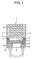
- FIG. 1 is a plan view.
- the humidity sensor device 1 includes a pair of interdigital electrodes 4 on an insulating substrate 2.
- the pair of interdigital electrodes 4 are disposed on the substrate 2 and interdigitated with each other to define a gap 5 of a certain distance therebetween.
- a humidity sensitive thin film 3 is formed over the insulating substrate 2 and interdigital electrodes 4.
- the interdigital electrodes 4 are provided at one end with electrode tabs 6 to which leads 7 are connected with solder welds 8.
- a resist film 9 is formed for preventing diffusion of the electrode material.
- AC voltage is applied across the electrodes. Since the humidity sensitive thin film changes its electrical resistance or impedance in accordance with the humidity, the output voltage changes therewith, in terms of which the humidity is detectable.
- the applied voltage is typically up to about 12 volts.
- the insulating substrate 2 and electrodes 4 used herein are as previously described.
- the electrode tabs 6 may be made of any conventional material which is compatible with the solder 8.
- Ag-Pd alloy is printed in a conventional manner and baked at high temperatures to form the electrode tabs 6.
- Au is used as the electrodes 4, it is preferred that the resist film 9 of resist or glass is further provided, as shown in FIG. 1, in order to prevent diffusion of Au during soldering. No limits are imposed on the thickness and configuration of the resist film 9 as long as it is effective for preventing diffusion of Au during soldering.
- the humidity sensor device of the present invention is not limited to the illustrated embodiment. Any desired shape or arrangement may be employed.
- the gap between a pair of electrodes is typically about 100 to 500 ⁇ m.
- the monomer of formula (2) and the monomer of formula (1) thus obtained were weighed in 0.5 g and 0.6 g, respectively, and 20.9 g of ethyl cellosolve was added thereto for dissolution.
- As a polymerization initiator 0.2% by weight of KAYACURE ABQ (Nippon Kayaku Co., Ltd.) was added thereto, giving a solution of the humidity sensitive thin film-forming monomers (coating solution). The solution was held at 4°C for storage.
- FIG. 1 A humidity sensor device as shown in FIG. 1 was fabricated.
- a porous ceramic substrate of alumina was used as the insulating substrate.
- Interdigital electrodes 4 were formed on the substrate by screen printing paste containing RuO 2 and glass frit and firing at high temperature. The gap between the electrodes 4 was about 225 ⁇ m.
- the interdigital electrode-bearing substrate was submerged in 100 ml of isopropyl alcohol, immersed therein for cleaning for 10 minutes while applying ultrasonic waves, and allowed to stand for drying. This operation was repeated three cycles.
- the humidity sensitive thin film-forming monomer solution was applied to the substrate by dispensing an aliquot of 2.75 ⁇ l per device. By holding at 25°C for 15 minutes for drying, a coating was formed. Then the coating was exposed to UV radiation in a nitrogen atmosphere for one minute for polymerization, yielding a humidity sensitive thin film. At this point, the exposure of UV radiation was 1,000 mJ/cm 2 .
- the humidity sensitive thin film had a thickness of about 5 ⁇ m.
- the humidity sensor device thus fabricated was evaluated for output and examined by a water resistance test.
- a divided flow humidity generating machine model SRH-1 (manufactured by Shinei K.K.) was used.
- the humidity sensor was incorporated in the circuit described and shown in JP-A 2-123843.
- the humidity sensor incorporated in the circuit was set in the humidity generating machine where the relative humidity was changed stepwise from a low level to a high level and then from the high level to the low level both at 25°C.
- the humidity sensor which was allowed to stand at a selected relative humidity for 30 minutes was measured for output voltage.
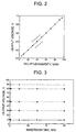
- the selected relative humidity levels were RH 5%, RH 10%, RH 20%, RH 30%, RH 40%, RH 50%, RH 60%, RH 70%, RH 80%, RH 90% and RH 95%.
- the results are plotted in FIG. 2.
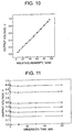
- the humidity sensor having undergone output voltage monitoring as mentioned above was immersed in distilled water for 1 minute, dried in air, and measured for output voltage again. Subsequently, the time duration when the humidity sensor was immersed in distilled water was prolonged to 10 minutes, 30 minutes and 60 minutes whereupon the output voltage was similarly measured at relative humidity levels of RH 10%, RH 30%, RH 50%, RH 80% and RH 90% for comparison. The results are plotted in FIG. 3.
- inventive humidity sensor develops a good response curve without hysteresis. It is evident from FIG. 3 that the inventive humidity sensor is fully resistant to water.
- Example 3 Comparative Example 2 Cl 2 -1.0 -1.2 -15.5 H 2 S -0.2 -0.2 -2.4 SO 2 -3.3 -3.5 -29.7 NO 2 -2.1 -2.6 -14.1 HCl -2.5 -3.1 -22.3 NH 3 -0.1 0.1 2.5
- An interdigital electrode-bearing alumina substrate which was prepared by the same procedure as in Example 1 was previously treated with an aqueous acetic acid solution of 1 wt% ⁇ -methacryloxypropyltrimethoxysilane (KBM503 by Shin-Etsu Chemical Co., Ltd.), dried, and held at 120°C for 20 minutes for thereby introducing acryloyl groups into the substrate surface. Thereafter, the substrate was dipped in the same humidity sensitive thin film-forming monomer solution as in Example 1, forming a coating. As in Example 1, UV radiation was irradiated to the coating for polymerization and crosslinking, obtaining a humidity sensor device.
- KBM503 aqueous acetic acid solution of 1 wt% ⁇ -methacryloxypropyltrimethoxysilane
- the humidity sensor device thus fabricated was subjected to output evaluation and a water resistance test as in Example 1.
- the measured results of output are shown in FIG. 4, and the measured results of the water resistance test are shown in FIG. 5.
- Example 1 Also a gas resistance test was carried out as in Example 1, obtaining satisfactory results as in Example 1.
- the amount of acetone used was 500 ml. The dry weight was 6.04 g. Subsequently, 5.07 g of the white precipitate was dissolved in 9 g of methanol. Dimethylaminopropylmethacrylamide, 2.98 g, was added to the solution and reaction was effected at an oil bath temperature of 90°C for 24 hours. The solution was in a dark orange viscous state. Methanol, 20 ml, was added to the solution, followed by reverse re-precipitation, obtaining a pale yellow precipitate. The yield was 2.47 g. An analysis by gel permeation chromatography (GPC) showed a number average molecular weight (Mn) of 2734.
- Mn number average molecular weight
- the monomer of formula (2) and the monomer of formula (1) thus obtained were weighed in 0.3 g and 0.6 g, respectively, and dissolved in 18 ml of water to prepare an aqueous solution of about 5% by weight.
- aqueous solution 0.2% by weight of KAYACURE ABQ (Nippon Kayaku Co., Ltd., benzophenone compound) was added as a polymerization initiator, giving a coating solution (humidity sensitive thin film-forming monomer solution).
- a humidity sensor device 1 as shown in FIG. 1 was fabricated.
- a porous ceramic substrate of alumina was used as the insulating substrate 2.
- Interdigital electrodes 4 were formed on the substrate by screen printing paste containing RuO 2 and glass frit and firing at high temperature. The gap between the electrodes 4 was about 225 ⁇ m.
- the coating solution was coated onto the insulating substrate 2 by dipping and dried at 50°C for 5 minutes, forming a coating. Then the coating on the electrode side was exposed to UV radiation in a nitrogen atmosphere for one minute for crosslinking, yielding a humidity sensitive thin film 3. At this point, the exposure of UV radiation was 1,000 mJ/cm 2 .
- the humidity sensitive thin film 3 had a thickness of about 5 ⁇ m.
- the humidity sensor device thus fabricated was subjected to output evaluation and a water resistance test as in Example 1. The measured results of output are shown in FIG. 6, and the measured results of the water resistance test are shown in FIG. 7.
- inventive humidity sensor develops a good response curve without hysteresis. It is evident from FIG. 7 that the inventive humidity sensor is fully resistant to water.
- Example 1 Also a gas resistance test was carried out as in Example 1, with the results shown in Table 1 together with the results of Example 1. The gas resistance was found satisfactory.
- An interdigital electrode-bearing alumina substrate which was prepared by the same procedure as in Example 3 was previously treated with an aqueous acetic acid solution of 1 wt% ⁇ -methacryloxypropyltrimethoxysilane (KBM503 by Shin-Etsu Chemical Co., Ltd.), dried, and held at 120°C for 20 minutes for thereby introducing acryloyl groups into the substrate surface. Thereafter, the substrate was dipped in the same humidity sensitive thin film-forming monomer solution as in Example 1 forming a coating. As in Example 3, UV radiation was irradiated to the coating for polymerization and crosslinking, obtaining a humidity sensor device.
- KBM503 aqueous acetic acid solution of 1 wt% ⁇ -methacryloxypropyltrimethoxysilane
- the humidity sensor device thus fabricated was subjected to output evaluation and a water resistance test as in Example 1.
- the measured results of output are shown in FIG. 8, and the measured results of the water resistance test are shown in FIG. 9.
- Example 3 Also a gas resistance test was carried out as in Example 1, obtaining satisfactory results as in Example 3.
- a monomer of formula (1) was synthesized by the same procedure as in Example 3 using 5.04 g (25.6 mmol) of N,N,N',N'-tetramethyl-1,12-dodecane diamine and 9.91 g (30.2 mmol) of 1,12-dibromododecane as the starting reactants.
- a monomer of formula (2) was synthesized by the same procedure as in Example 1 using 9.88 g (66.9 mmol) of 2-dimethylaminoethyl methacrylate and 3.68 g (33.3 mmol) of 1,3-dichloropropane as the starting reactants.
- the monomer of formula (2) and the monomer of formula (1) thus obtained were weighed in 0.1 g and 0.5 g, respectively, and dissolved in 12 ml of water to prepare an aqueous solution of about 5% by weight.
- a humidity sensor device was fabricated by the same procedure as in Example 1.
- the humidity sensor device thus fabricated was subjected to output evaluation and a water resistance test as in Example 1.
- the measured results of output are shown in FIG. 10, and the measured results of the water resistance test are shown in FIG. 11.
- Example 3 Also a gas resistance test was carried out as in Example 1, obtaining satisfactory results as in Example 3.
- Humidity sensor devices were fabricated as in Example 3 aside from using the monomer of formula (2) and the monomer of formula (1) separately.
- the measured results of output from the device using the monomer of formula (1) are shown in FIG. 12, and the measured results of a water resistance test from the device using the monomer of formula (2) are shown in FIG. 13.
- the device using the monomer of formula (2) developed substantially equivalent performance to Example 3, but the device using the monomer of formula (1) produced low outputs over the entire range, with hysteresis observed in the low-humidity region as shown in FIG. 12. Both the devices were satisfactory in the gas resistance test. In the water resistance test, however, the device using the monomer of formula (2) produced somewhat reduced outputs as shown in FIG. 13, and the device using the monomer of formula (1) was poorly resistant to water.
- a humidity sensor device was fabricated as in Example 3 except that on an alumina substrate on which interdigital electrodes were formed as in Example 3, a humidity sensitive thin film of 0.1 ⁇ m thick was formed by applying and crosslinking a copolymer (number average molecular weight 110,000) in the form of an ionene polymer having an acrylamide group introduced at either end which was obtained by reacting 8.6 g of N,N,N',N'-tetramethyldiaminohexane with 6.8 g of 1,3-dichloropropane as described in JP-A 7-318526.
- a copolymer number average molecular weight 110,000
- Example 2 The device was evaluated as in Example 1, finding nearly satisfactory results with respect to the humidity response performance and water resistance.
- the results of a gas resistance test are shown in Table 1 together with the results of Examples 1 and 3, indicating poor gas resistance.
- a humidity sensor device was fabricated as in Example 3 except that 0.015 g of divinyl benzene was used instead of the monomer of formula (1). The device was similarly evaluated. No problems were found with respect to the water resistance and gas resistance. The device produced low outputs because of an increased impedance.
- a humidity sensor device 1 as shown in FIG. 1 was fabricated.
- a porous ceramic substrate of alumina was used as the insulating substrate 2.
- Interdigital electrodes 4 were formed on the substrate by screen printing paste containing RuO 2 and glass frit and firing at high temperature. The gap between the electrodes 4 was about 225 ⁇ m.
- the interdigital electrode-bearing substrate was placed in 100 ml of isopropyl alcohol, immersed therein for 10 minutes for cleaning, and allowed to stand for drying.
- a plasma treatment was carried out using a plasma dry cleaner model PDC200 by Yamato Science Co., Ltd. After 100 samples to be treated were placed, the chamber was evacuated to vacuum by operating a vacuum pump EC-403 by ULVAC Co. for 10 minutes. Oxygen gas was fed to the chamber at a flow rate of 300 sccm (0.51 Pa ⁇ m 3 ⁇ s -1 ) while a vacuum of 55 Pa was maintained. A plasma was generated at an RF power of 200 W, with which the samples were treated for one minute. The distance between electrodes was 10 cm.
- Example 3 Immediately after the treatment, a humidity sensitive thin film was formed as in Example 3.
- the humidity sensor device thus fabricated was subjected to output evaluation and a water resistance test as in Example 1.
- the measured results of output are shown in FIG. 14, and the measured results of the water resistance test are shown in FIG. 15.
- a humidity sensor device was fabricated as in Example 8 except that the interdigital electrode-bearing substrate was plasma treated under atmospheric pressure. The device was similarly evaluated for performance, obtaining likewise satisfactory results.
- the plasma treatment in this Example used an atmospheric pressure plasma cleaning apparatus by Matsushita Electric Machine & Vision Co., Ltd. Treatment was carried out by applying an oxygen plasma at a power of 700 W, an irradiation distance of 5 mm, and a head moving speed of 10 mm/sec and then a hydrogen plasma under the same conditions.
- a humidity sensor device 1 as shown in FIG. 1 was fabricated.
- a porous ceramic substrate of alumina was used as the insulating substrate 2.
- Interdigital electrodes 4 were formed on the substrate by screen printing paste containing RuO 2 and glass frit and firing at high temperature. The gap between the electrodes 4 was about 225 ⁇ m.
- the coating solution was coated onto the insulating substrate 2 by dipping and dried at 50°C for 5 minutes, forming a coating. Then the coating both on the electrode side and the back side was exposed to UV radiation in a nitrogen atmosphere for one minute on each side for crosslinking, yielding a humidity sensitive thin film 3. At this point, the exposure of UV radiation was 1,000 mJ/cm 2 .
- the humidity sensitive thin film 3 had a thickness of 8 ⁇ m.
- the thus obtained film was treated for 2 hours in an atmosphere of 60°C and RH 80% for causing hydroxyl groups on the substrate and electrode surface to react with alkoxysilyl or silanol groups.
- the humidity sensor device thus fabricated was evaluated for output and examined by a water resistance test.
- a divided flow humidity generating machine model SRH-1 (manufactured by Shinei K.K.) was used.
- the humidity sensor was incorporated in the circuit described and shown in JP-A 2-123843.
- the humidity sensor incorporated in the circuit was set in the humidity generating machine where the relative humidity was changed stepwise from a low level to a high level and then from the high level to the low level both at 25°C.
- the humidity sensor which was allowed to stand at a selected relative humidity for 10 minutes was measured for output voltage.
- the selected relative humidity levels were RH 0%, RH 10%, RH 20%, RH 30%, RH 50%, RH 70% and RH 90%. The results are plotted in FIG. 16.
- the humidity sensor having undergone output voltage monitoring as mentioned above was immersed in distilled water for 1 minute, dried in air, and measured for output voltage again for comparison. Subsequently, the time duration when the humidity sensor was immersed in distilled water was prolonged to 10 minutes, 30 minutes and 60 minutes whereupon the output voltage was similarly measured for comparison. The results are plotted in FIG. 17.
- the inventive humidity sensor develops no hysteresis and can measure a low humidity, especially in the region of not higher than RH 10%.
- An interdigital electrode-bearing alumina substrate which was prepared by the same procedure as in Example 10 was previously treated with an aqueous acetic acid solution of 1 wt% ⁇ -methacryloxypropyltrimethoxysilane (KBM503) for introducing acryloyl groups into the substrate surface.
- KBM503 aqueous acetic acid solution of 1 wt% ⁇ -methacryloxypropyltrimethoxysilane
- UV radiation was irradiated to the coating for polymerization and crosslinking, obtaining a humidity sensor device.
- the humidity sensor device thus fabricated was subjected to output evaluation and a water resistance test as in Example 10.
- the measured results of output are shown in FIG. 18, and the measured results of the water resistance test are shown in FIG. 19.
- Example 10 Also a gas resistance test was carried out as in Example 10, obtaining satisfactory results as in Example 10.
- a device was fabricated as in Example 10 except that the silane coupling agent was omitted.
- the humidity response performance was substantially equivalent as shown in FIG. 20. No problem was found with respect to the gas resistance test. In the water resistance test, however, the humidity sensitive thin film immediately peeled as a whole, and outputs were no longer produced.
- a humidity sensor device as shown in FIG. 1 was fabricated.
- a porous ceramic substrate of alumina was used as the insulating substrate.
- Interdigital electrodes 4 were formed on the substrate by screen printing paste containing RuO 2 and glass frit and firing at high temperature. The gap between the electrodes 4 was about 225 ⁇ m.
- the interdigital electrode-bearing substrate was placed in 100 ml of isopropyl alcohol, immersed therein for 10 minutes for cleaning, and allowed to stand for drying.
- a plasma treatment was carried out using a plasma dry cleaner model PDC200 by Yamato Science Co., Ltd. After 100 samples to be treated were placed, the chamber was evacuated to vacuum by operating a vacuum pump EC-403 by ULVAC Co. for 10 minutes. Oxygen gas was fed to the chamber at a flow rate of 300 sccm (0.51 Pa ⁇ m 3 ⁇ s -1 ) while a vacuum of 55 Pa was maintained. A plasma was generated at an RF power of 700 W, with which the samples were treated for one minute. The distance between electrodes was 10 cm.
- the humidity sensitive thin film-forming monomer solution was applied to the substrate by dispensing an aliquot of 2.2 ⁇ l per device. By holding at 25°C for 15 minutes for drying, a coating was formed. Then the coating was exposed to UV radiation in a nitrogen atmosphere for one minute for polymerization, yielding a humidity sensitive thin film. At this point, the exposure of UV radiation was 1,000 mJ/cm 2 .
- the humidity sensitive thin film had a thickness of about 4 ⁇ m.
- the humidity sensor device thus fabricated was evaluated for output and examined by a water resistance test.
- a divided flow humidity generating machine model SRH-1 (manufactured by Shinei K.K.) was used.
- the humidity sensor was incorporated in the circuit described and shown in JP-A 2-123843.
- the humidity sensor incorporated in the circuit was set in the humidity generating machine where the relative humidity was changed stepwise from a low level to a high level and then from the high level to the low level both at 25°C.
- the humidity sensor which was allowed to stand at a selected relative humidity for 30 minutes was measured for output voltage.
- the selected relative humidity levels were RH 5%, RH 10%, RH 20%, RH 30%, RH 40%, RH 50%, RH 60%, RH 70%, RH 80%, RH 90% and RH 95%.
- the results are plotted in FIG. 21.
- the humidity sensor having undergone output voltage monitoring as mentioned above was immersed in distilled water for 1 minute, dried in air, and measured for output voltage again. Subsequently, the time duration when the humidity sensor was immersed in distilled water was prolonged to 10 minutes, 30 minutes and 60 minutes whereupon the output voltage was similarly measured at relative humidity levels of RH 10%, RH 30%, RH 50%, RH 80% and RH 90% for comparison. The results are plotted in FIG. 22.
- inventive humidity sensor develops a good response curve without hysteresis. It is evident from FIG. 22 that the inventive humidity sensor is fully resistant to water.
- Example 10 Also a gas resistance test was carried out as in Example 10, obtaining satisfactory results as in Example 10.
- a humidity sensor device was fabricated as in Example 12 except that the interdigital electrode-bearing substrate was plasma treated under atmospheric pressure. The device was similarly evaluated for performance, obtaining likewise satisfactory results.
- the plasma treatment in this Example used an atmospheric pressure plasma cleaning apparatus by Matsushita Electric Machine & Vision Co., Ltd. Treatment was carried out by applying an oxygen plasma at a power of 700 W, an irradiation distance of 5 mm, and a head moving speed of 10 mm/sec and then a hydrogen plasma under the same conditions.
- the monomer of formula (2) was dissolved in ethyl cellosolve to form 10 ml of a 5 wt% solution, to which 0.2% by weight of KAYACURE ABQ (Nippon Kayaku Co., Ltd.) was added as a polymerization initiator, giving a solution of the humidity sensitive thin film-forming monomer.
- the solution was held at 4°C for storage.
- a humidity sensor device 1 as shown in FIG. 1 was fabricated.
- a porous ceramic substrate of alumina was used as the insulating substrate 2.
- Interdigital electrodes 4 were formed on the substrate by screen printing paste containing RuO 2 and glass frit and firing at high temperature. The gap between the electrodes 4 was about 225 ⁇ m.
- the interdigital electrode-bearing substrate was submerged in 100 ml of isopropyl alcohol, immersed therein for cleaning for 10 minutes, and allowed to stand for drying.
- a plasma treatment was carried out using a plasma dry cleaner model PDC200 by Yamato Science Co., Ltd. After 100 samples to be treated were placed, the chamber was evacuated to vacuum by operating a vacuum pump EC-403 by ULVAC Co. for 10 minutes. Oxygen gas was fed to the chamber at a flow rate of 300 sccm (0.51 Pa ⁇ m 3 ⁇ s -1 ) while a vacuum of 55 Pa was maintained. A plasma was generated at an RF power of 700 W, with which the samples were treated for one minute. The distance between electrodes was 10 cm.
- the humidity sensitive thin film-forming monomer solution was applied to the substrate by dispensing an aliquot of 2.75 ⁇ l per device. By holding at 25°C for 15 minutes for drying, a coating was formed. Then the coating was exposed to UV radiation in a nitrogen atmosphere for one minute for polymerization, yielding a humidity sensitive thin film. At this point, the exposure of UV radiation was 1,000 mJ/cm 2 .
- the humidity sensitive thin film had a thickness of 5 ⁇ m.
- the humidity sensor device thus fabricated was evaluated for output and examined by a water resistance test.
- a divided flow humidity generating machine model SRH-1 (manufactured by Shinei K.K.) was used.
- the humidity sensor was incorporated in the circuit described and shown in JP-A 2-123843.
- the humidity sensor incorporated in the circuit was set in the humidity generating machine where the relative humidity was changed stepwise from a low level to a high level and then from the high level to the low level both at 25°C.
- the humidity sensor which was allowed to stand at a selected relative humidity for 30 minutes was measured for output voltage.
- the selected relative humidity levels were RH 5%, RH 10%, RH 20%, RH 30%, RH 40%, RH 50%, RH 60%, RH 70%, RH 80%, RH 90% and RH 95%.
- the results are plotted in FIG. 23.
- the humidity sensor having undergone output voltage monitoring as mentioned above was immersed in distilled water for 1 minute, dried in air, and measured for output voltage again. Subsequently, the time duration when the humidity sensor was immersed in distilled water was prolonged to 10 minutes, 30 minutes and 60 minutes whereupon the output voltage was similarly measured at relative humidity levels of RH 10%, RH 30%, RH 50%, RH 80% and RH 90% for comparison. The results are plotted in FIG. 24.
- inventive humidity sensor develops a good response curve without hysteresis. It is evident from FIG. 24 that the inventive humidity sensor is fully resistant to water.
- a gas resistance test was carried out. Gas resistance was tested by measuring outputs of the humidity sensor at different relative humidity levels, confirming a linear response thereof, then holding the sensor under conditions: temperature 40°C and humidity RH 70°C to 80% for 100 hours while flowing nitrogen dioxide gas, hydrogen chloride gas, ammonia gas, sulfur dioxide gas, chlorine gas and hydrogen sulfide gas each in a concentration of 5 ppm, measuring again a humidity-representing output (%RH) of the humidity sensor at a preset relative humidity level (%RH), and determining a maximum change (%RH). In all the tests, the percent change, though somewhat varied depending on the type of gas, fell within the range between -5% and +5%, indicating satisfactory gas resistance.
- a plasma treatment was carried out using an atmospheric pressure plasma cleaning apparatus by Matsushita Electric Machine & Vision Co., Ltd. Treatment was carried out by applying an oxygen plasma at a power of 700 W, an irradiation distance of 5 mm, and a head moving speed of 10 mm/sec and then a hydrogen plasma under the same conditions.
- Example 14 Thereafter, as in Example 14, a humidity sensitive thin film was formed and a humidity sensor device fabricated.
- the humidity sensor device thus fabricated was subjected to output evaluation and a water resistance test as in Example 1.
- the measured results of output are shown in FIG. 25, and the measured results of the water resistance test are shown in FIG. 26.
- Example 14 Also a gas resistance test was carried out as in Example 14. The percent change fell within the range between -5% and +5%, with no problems found with respect to the gas resistance.
- a humidity sensitive thin film-forming monomer solution was prepared from this substance by the same procedure as in Example 14. After plasma treatment was carried out under the same conditions as in Example 14, a humidity sensitive thin film was formed, and a humidity sensor device fabricated.
- the humidity sensor device thus fabricated was subjected to output evaluation and a water resistance test as in Example 14.
- the measured results of output are shown in FIG. 27, and the measured results of the water resistance test are shown in FIG. 28.
- Example 14 Also a gas resistance test was carried out as in Example 14. The percent change fell within the range between -5% and +5%, with no problems found with respect to the gas resistance.
- a humidity sensor device was fabricated as in Example 14 except that the time of plasma treatment was 10 minutes, and the interdigital electrode-bearing substrate after the plasma treatment was vacuum held in a desiccator for 24 hours.
- the humidity sensor device thus fabricated was subjected to output evaluation and a water resistance test as in Example 14.
- the measured results of output are shown in FIG. 29, and the measured results of the water resistance test are shown in FIG. 30.
- Example 14 Also a gas resistance test was carried out as in Example 14. The percent change fell within the range between -5% and +5%, with no problems found with respect to the gas resistance.
- a humidity sensor device was fabricated as in Example 14 except that some plasma treatment conditions were changed to an Ar gas flow rate of 15 sccm (0.0255 Pa ⁇ m 3 ⁇ s -1 ) and a time of 2 minutes.
- the humidity sensor device thus fabricated was subjected to output evaluation and a water resistance test as in Example 14.
- the measured results of output are shown in FIG. 31, and the measured results of the water resistance test are shown in FIG. 32.
- Example 14 Also a gas resistance test was carried out as in Example 14. The percent change fell within the range between -5% and +5%, with no problems found with respect to the gas resistance.
- a humidity sensor device was fabricated as in Example 14 except that UV/ozone treatment was carried out instead of the plasma treatment.
- the UV/ozone treatment was carried out for 10 minutes under conditions of 4.5 W x 2 using a UV ozone cleaner NL-UV252 by Nippon Laser Electron Co., Ltd.
- the humidity sensor device thus fabricated was subjected to output evaluation and a water resistance test as in Example 14.
- the measured results of output are shown in FIG. 33, and the measured results of the water resistance test are shown in FIG. 34.
- Example 14 Also a gas resistance test was carried out as in Example 14. The percent change fell within the range between -5% and +5%, with no problems found with respect to the gas resistance.
- the interdigital electrode-bearing substrate Prior to the fabrication of a humidity sensor device, the interdigital electrode-bearing substrate was submerged in 100 ml of isopropyl alcohol, immersed therein for cleaning for 10 minutes while applying ultrasonic waves, and allowed to stand for drying. This operation was repeated three cycles.
- the interdigital electrode-bearing substrate without plasma treatment, was coated with the humidity sensitive thin film-forming monomer solution as in Example 14, and a humidity sensor device fabricated as in Example 14.
- the humidity sensor device thus fabricated was subjected to output evaluation and a water resistance test as in Example 14.
- the measured results of output are shown in FIG. 35, and the measured results of the water resistance test are shown in FIG. 36.
Landscapes
- Chemical & Material Sciences (AREA)
- Chemical Kinetics & Catalysis (AREA)
- Electrochemistry (AREA)
- Physics & Mathematics (AREA)
- Health & Medical Sciences (AREA)
- Life Sciences & Earth Sciences (AREA)
- Analytical Chemistry (AREA)
- Biochemistry (AREA)
- General Health & Medical Sciences (AREA)
- General Physics & Mathematics (AREA)
- Immunology (AREA)
- Pathology (AREA)
- Investigating Or Analyzing Materials By The Use Of Fluid Adsorption Or Reactions (AREA)
- Investigating Or Analyzing Materials By The Use Of Electric Means (AREA)
Abstract
In a humidity sensor device comprising a pair of
opposed electrodes disposed on an insulating substrate to
define a gap therebetween and a humidity sensitive thin
film lying on the gap, the humidity sensitive thin film is
a thin film comprising a polymer or copolymer obtained from
a monomer of formula (1), and formation of the humidity
sensitive thin film is optionally combined with treatment
of the insulating substrate by physical means. A humidity
sensor device for detecting and determining moisture in the
surrounding atmosphere which has improved water resistance,
solvent resistance, and gas resistance, and exhibits stable
output performance in a wide humidity region without
hysteresis is provided as well as a method for preparing
the same.
 In formula (1), A11 is a divalent group, R11 to R14 are
alkyl, Y11 and Y12 are monovalent groups terminated with an
ethylenically unsaturated reactive group, any two or more
of R11 to R14, Y11, Y12, A11 and portions thereof adjoining the
nitrogen (N) atom may bond together to form a ring with the
nitrogen (N) atom, and X11 - and X12 - are anions.
In formula (1), A11 is a divalent group, R11 to R14 are
alkyl, Y11 and Y12 are monovalent groups terminated with an
ethylenically unsaturated reactive group, any two or more
of R11 to R14, Y11, Y12, A11 and portions thereof adjoining the
nitrogen (N) atom may bond together to form a ring with the
nitrogen (N) atom, and X11 - and X12 - are anions.
Description
This invention relates to a humidity sensor device
for detecting and determining moisture in the surrounding
atmosphere and a method for preparing the same.
Known humidity sensors designed to detect humidity
through changes of electrical properties, typically
electric resistance include those using electrolytes such
as lithium chloride, metal oxides, and organic polymers as
the humidity sensitive material.
However, the humidity sensors using electrolytes such
as lithium chloride can measure only a narrow range of
humidity and are less resistant to water in that their
performance can be altered by dew condensation and wetting.
The humidity sensors using metal oxides are resistant to
water, but low sensitive. Because of the lack of long-term
stability when used alone, they undesirably require a heat
cleaning circuit which would add to the operating cost and
make the sensor structure complex.
Among the humidity sensitive materials, organic
polymers, especially polymeric electrolytes having
quaternary ammonium salt have been widely used in
commercial and industrial applications and so appreciated.
For example, Japanese Patent Publication (JP-B) No.
61-54176 discloses a humidity sensitive material comprising
aggregates of latex particles formed of a copolymer between
a hydrophobic monomer and an ionic or non-ionic hydrophilic
monomer and having a hydrophilic surface layer. There are
exemplified some cationic compounds having primary to
quaternary ammonium salts.
JP-B 62-7976 discloses a humidity sensitive material
in the form of a polymer which is obtained by polymerizing
a compound containing 2-hydroxy-3-methacryloxypropyltrimethylammonium
chloride to a degree of polymerization of
1,000 to 10,000.
JP-B 2-24465 discloses the use as a humidity
sensitive polymeric thin film of a thin film of an ionene
polymer having the structural formula:
-(N+(R1)(R2)X--A-N+(R3)(R4)X--B)n-
wherein R1 to R4 are alkyl, X- is a halide ion, A and B
each are -(CH2)m- wherein m ≥ 2, or a thin film of a
mixture of the polymer with another polymer such as
polyvinyl pyrrolidone for the purposes of improving
substrate adhesion and water resistance.
Humidity sensors using the polymeric electrolytes
exemplified above as the humidity sensitive material,
however, are still low in water resistance in that the
polymeric electrolytes can be partially leached in a high
humidity region, especially in a dew condensing atmosphere.
They also suffer from a hysteresis phenomenon that they
produce different outputs at the same humidity depending on
whether the humidity is increasing or decreasing. In a low
humidity region having a relative humidity (RH) of less
than 10%, they have so high resistance values that
practical humidity measurement is impossible.
JP-A 7-318526 discloses that water resistance is
improved by introducing an unsaturated bond into the ionene
polymer at either end and crosslinking with ultraviolet
radiation. In this case, a very thin film provides
satisfactory properties and water resistance. However, the
small thickness means so small an absolute amount of the
polymer that the film is vulnerable to a gas which is
dissolved in water to form ions (e.g., Cl2, NOx, SOx). The
problem is serious particularly in a commercial application.
The conductivity of a film having a thickness above a
certain level is not substantially altered even when gas-origin
ions are created in the surface layer. The polymer
layer obtained by the above crosslinking method, however,
undergoes substantial swell upon absorption of water,
giving rise to serious problems of crack generation and
separation from the substrate. Under such circumstances,
the film must be used at a thickness of no more than 1 µm.
A primary object of the present invention is to
provide a humidity sensor device having a humidity
sensitive thin film which is resistant to water, maintains
effective, stable performance over a long time even in a
dew condensing atmosphere, is resistant to solvents and
less vulnerable to gases such as nitrogen oxides, sulfur
oxide and chlorine, and produces accurate outputs in a
stable manner over a wide humidity region, especially in a
low humidity region; and a method for preparing the same.
Another object is to provide a simple method for preparing
such a humidity sensor device having improved properties as
mentioned above.
These and other objects are achieved by the present
invention which is defined below as (1) to (32).
said humidity sensitive thin film comprising a copolymer of at least one monomer of the following formula (1) with at least one monomer of the following formula (2):

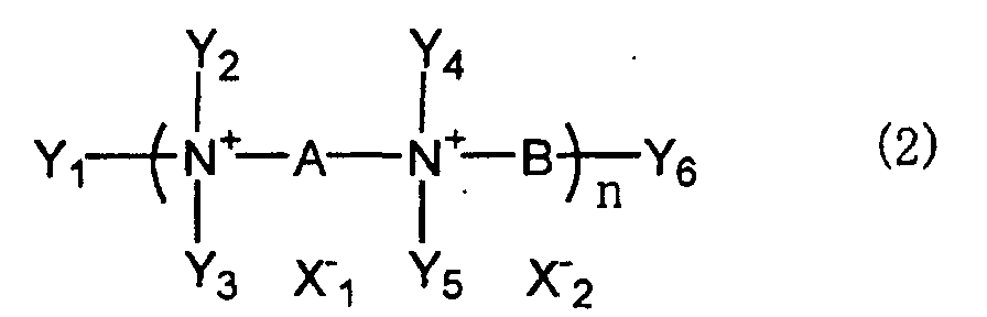

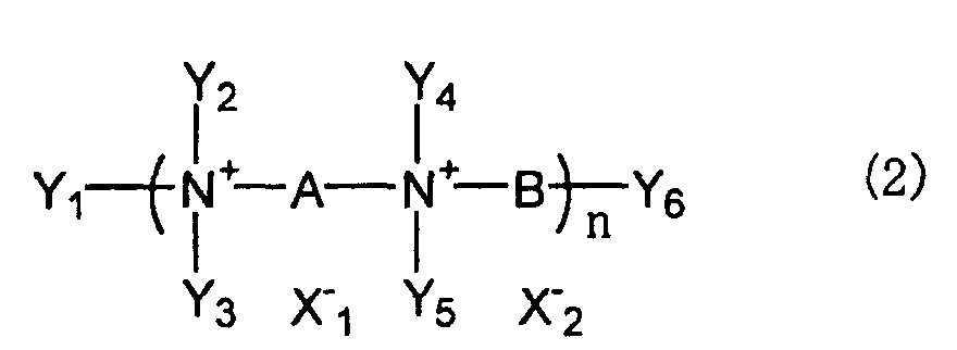
said humidity sensitive thin film comprising a copolymer of a monomer of the following formula (1) with an acrylic monomer having an alkoxysilyl group,


According to the invention, a humidity sensitive thin
film of an electrically conductive polymer is formed so as
to cover a pair of opposed electrodes on an insulating
substrate.
In the first embodiment of the present invention, the
humidity sensitive thin film is obtained by furnishing at
least one of crosslinking monomers of formula (1)
(abbreviated as monomer of formula (1), hereinafter) and at
least one of crosslinking monomers of formula (2)
(abbreviated as monomer of formula (2), hereinafter), that
is, at least two monomers together, and causing the
monomers to polymerize together by suitable means such as
ultraviolet irradiation or heating. As seen from the
monomers of formulae (1) and (2), the copolymer obtained
therefrom is characterized by the possession of an ionene
polymer structure having a quaternary ammonium salt
(inclusive of cyclized one).
Since the monomers are preferably difunctional or
have two acrylic unsaturated reactive groups, the
crosslinking copolymer undergoes three-dimensional reaction
to form a crosslinked structure which becomes insoluble in
water.
In the humidity sensitive thin film using the
crosslinking copolymer of ionene polymer structure, the
quaternary ammonium salt moiety contained in the copolymer
molecule contributes to electric conductivity and the
counter ion thereto is dissociated with moisture in the
surrounding atmosphere to develop ionic conduction.
Humidity is detected by utilizing the phenomenon that the
degree of dissociation varies as the moisture content in
the atmosphere increases or decreases. In the first
embodiment of the invention wherein the ionene polymer
structure is included in the crosslinking copolymer, the
copolymer is close to the backbone type with a less degree
of freedom unlike the so-called pendant type. Its humidity
response does not develop hysteresis.
The humidity sensitive film which is formed by
copolymerization of monomers on the electrodes does not
always have a uniform distribution of crosslinking sites
within it because polymerization takes place in a dry state.
This is because, when copolymerization is effected by
exposure to UV radiation, for example, the difference of
photon density between the surface and the interior of the
film becomes large in the case of solids, with the tendency
that an outer side has a higher crosslinking density. The
humidity sensitive film is more likely to crack upon
swelling due to water absorption as it becomes thicker. It
is then necessary to make the crosslinking density uniform
or to increase the number of crosslinking sites.
Therefore, the first embodiment of the invention is
characterized in that the monomer of formula (1) which can
assume an ionene polymer structure having improved
properties when polymerized to form a humidity sensitive
material is combined as the crosslinking agent with the
monomer of formula (2), for thereby increasing the number
of crosslinking sites while maintaining a low impedance.
Since the monomer of formula (1) and the monomer of formula
(2), which differ in molecular weight, are analogous
monomers in that they can possess an ionene polymer
structure within them, they enable to increase the number
of crosslinking sites without reducing the ion density.
From the standpoint of device design, by changing the
molecular weight and mixing ratio of the monomer of formula
(2), the factor of greater interest can be selected among
basic factors of the humidity sensor including water
resistance, gas resistance and hysteresis, which enables
free design. An increase of ion density improves gas
resistance, and an increase of crosslinking density
improves water resistance. As the molecular weight
increases, the monomer of formula (2) becomes more flexible,
which restrains cracking after swelling. It is noted that
to ensure water resistance in this case, the content of the
monomer of formula (1) must be increased to enhance the
degree of crosslinking. On the other hand, extreme
crosslinking increases the possibility of hysteresis, which
necessitates appropriate adjustment.
Referring to formulae (1) and (2), the structural
factors that dictate the conductivity of the crosslinking
copolymer include the number of carbon atoms in the
backbone of A and B in formula (2) and A11 in formula (1)
(i.e., the length of divalent linking group), the type of
anions X1 - and X2 - in formula (2), and X11 - and X12 - in formula
(1). Therefore, a sensor device having desired properties
can also be designed by combining the monomers in which
these parameters are suitable selected.
In contrast, with respect to crosslinking agents
which are commonly added in order to increase the number of
crosslinking sites, such as divinyl benzene, it is
confirmed that the strength of the film and the number of
crosslinking sites are increased by adding them to the
monomer of formula (2). However, such a customary
crosslinking agent results in a humidity sensitive film
which has an increased impedance because its swelling is
suppressed due to the increased number of crosslinking
sites by the addition of the crosslinking agent and because
the crosslinking agent itself lacks electric conductivity.
It is not suitable as the humidity sensitive film for
humidity sensors.
JP-B 2-24465 cited above discloses a polymer
containing a quaternary ammonium salt in its backbone,
which is similar to the polymer according to the first
embodiment of the invention. Unlike the first embodiment
of the invention, the formation of a crosslinking structure
within the polymer is referred to nowhere. In this respect,
the first embodiment of the present invention is clearly
different in construction and features from the patent
publication. Although the combined use of another polymer
such as polyvinyl pyrrolidone for the purpose of improving
water resistance is recommended in the patent publication,
the water resistance is apparently inferior.
Likewise, in JP-A 4-309855 and JP-A 7-128271, a
methacryloxypropyl trimethyl ammonium salt having a
hydroxyl group and trimethylolpropane trimethacrylate are
applied to form a coating, after which the coating is
polymerized and insolubilized for allegedly improving water
resistance. What is disclosed is a method of mixing two or
more polymers, followed by polymerization. Since the
ammonium group on the humidity sensitive material is the
so-called pendant type, the humidity response develops
substantial hysteresis.
In the second embodiment of the present invention,
the humidity sensitive thin film contains a crosslinking
copolymer of a monomer of formula (1) with an acrylic
monomer having an alkoxysilyl group. Then the humidity
sensitive thin film is joined to the insulating substrate
through reaction with the silane coupling agent within the
molecule. That is, the humidity sensitive thin film is
obtained by coating an aqueous solution or organic solvent
solution of the monomer and the silane coupling agent
having an acrylic unsaturated bond, drying, and subjecting
the monomer and the silane coupling agent to
copolymerization and crosslinking by irradiation of UV
radiation and/or heating. The copolymer is characterized
by having an ionene polymer structure having a quaternary
ammonium salt (including cyclized one) as seen from the
monomer of formula (1) and the silane coupling agent within
the molecule.
In the humidity sensitive thin film using the
crosslinking copolymer of ionene polymer structure, the
quaternary ammonium salt moiety contained in the copolymer
molecule contributes to electric conductivity and the
counter ion thereto is dissociated with moisture in the
surrounding atmosphere to develop ionic conduction.
Humidity is detected by utilizing the phenomenon that the
degree of dissociation varies as the moisture content in
the atmosphere increases or decreases. In the second
embodiment of the invention wherein the ionene polymer
structure is included in the crosslinking copolymer, the
copolymer is close to the backbone type with a less degree
of freedom unlike the so-called pendant type. Its humidity
response does not develop hysteresis.
In the invention, the ion density and crosslinking
degree of the humidity sensitive film can be controlled by
adjusting the length of divalent linking group A11. This
leads to the design that permits the factor of greater
interest to be selected among factors including water
resistance, gas resistance and hysteresis, which enables
free design. An increase of ion density improves gas
resistance, and an increase of crosslinking density
improves water resistance. On the other hand, extreme
crosslinking increases the possibility of hysteresis.
Since the monomers are preferably difunctional or
have two acrylic unsaturated reactive groups, the
crosslinking copolymer undergoes three-dimensional reaction
to form a crosslinked structure which becomes insoluble in
water. Since the silane coupling agent structure is
included within the molecule, the copolymer can be firmly
joined to the substrate through covalent bonds by reacting
with functional groups such as hydroxyl groups on the
substrate surface and/or electrode surface. These bonds
ensure that the humidity sensitive thin film remains water
resistant without becoming loose or peeling even when it is
thick. The humidity sensor has improved water resistance
and gas resistance as well as improved solvent resistance.
In the embodiment wherein the counter ion to the
quaternary ammonium salt group in the copolymer is a
chloride ion, a low humidity region of RH 10% or lower can
be measured, substantially spreading the measurable
humidity region. The humidity sensor of the invention can
measure humidity over the entire range from RH 0% to RH
100%, which was unmeasurable with conventional sensors.
JP-B 2-24465 cited above discloses a polymer
containing a quaternary ammonium salt in its backbone,
which is similar to the polymer according to the second
embodiment of the invention. Unlike the present invention,
the structure having the silane coupling agent incorporated
within the polymer and the crosslinking structure are
referred to nowhere. Therefore, the second embodiment of
the present invention is clearly different in construction
and features from the patent publication. Although the
combined use of another polymer such as polyvinyl
pyrrolidone for the purpose of improving water resistance
is recommended in the patent publication, the water
resistance is apparently inferior.
Also, JP-A 4-258750 intends to improve water
resistance by using an acrylic polymer having a cationic
radical and a hydroxyl group and a polyfunctional
isocyanate compound to form a three-dimensionally
crosslinked polymer. With this method, it is expected that
some of isocyanate is joined to the substrate surface by
reacting with hydroxyl groups on the substrate surface, but
its effect is little.
Likewise, in JP-A 4-309855 and JP-A 7-128271, a
methacryloxypropyl trimethyl ammonium salt having a
hydroxyl group and trimethylolpropane trimethacrylate are
applied to form a coating, after which the coating is
polymerized and insolubilized for allegedly improving water
resistance. However, this fails to achieve a substantial
improvement in the adhesion to the substrate.
Furthermore, JP-A 7-318525 discloses a bonding method
involving treating a substrate with silicon tetrachloride,
and reacting with poly(2-hydroxy-3-methacryloxypropyl)
trimethyl ammonium salt for thereby reacting the substrate
surface with hydroxyl groups in the polymer. This method
establishes the adhesion of the humidity sensitive film to
the substrate, but encounters difficulty in reproducing
substrate treating conditions because of the high
reactivity and storage instability of silicon
tetrachloride. Also, since the ammonium group of the
humidity sensitive material is of the so-called pendant
type, it is unavoidable that humidity response develops
hysteresis.
In the third embodiment of the present invention
wherein contaminants and/or oxides on the uppermost surface
layer of the insulating substrate are removed by physical
means before a humidity sensitive thin film is formed, the
humidity sensitive thin film is comprised of a polymer
obtained from a monomer of formula (1), obviating the use
of a monomer of formula (2) and an acrylic monomer having
an alkoxysilyl group.
The insulating substrate on which the humidity
sensitive film is to be formed is, most often, an alumina
substrate whose uppermost surface layer is covered with
contaminants, adsorbed gases, organic matter and oxides of
the substrate itself, which preclude the humidity sensitive
film from adhering thereto. The removal of contaminants
improves the adhesion of the humidity sensitive thin film
to the insulating substrate.
The reason why treatment is done by physical means is
that treatment by chemical means, which can remove
contaminants and organic matter, is not preferable because
of difficulty to remove the oxide layer and the problem of
used solution at the end of chemical treatment. In
contrast, the treatment by physical means can remove
contaminants and oxides in a relatively simple manner while
minimizing damage to the underlay. The material which is
treated by physical means may be selected from a wide
variety.
Among several physical means, plasma surface
treatment is highly effective and preferable. The plasma
surface treatment (to be referred to as "plasma treatment,"
hereinafter) means that active electrons, radicals, ions
and molecules in a plasma interact with the insulating
substrate surface to exert etching and implantation effects
for thereby modifying the surface state.
The plasma to be generated varies with the plasma
generating atmosphere and is generally divided into oxygen
plasma and hydrogen plasma depending on the gas species
used. Use of both oxygen plasma and hydrogen plasma is
preferred. Oxygen plasma is effective for removal of
surface organic contaminants and surface modification, and
hydrogen plasma is able to reduce metal oxides.
In the third embodiment of the invention wherein
contaminants and/or oxides on the uppermost surface layer
of the insulating substrate are removed by plasma-assisted
physical means, the adhesion between the humidity sensitive
thin film and the insulating substrate is presumably
enhanced by the two mechanisms described below.
First, contaminants and oxides on the uppermost
surface layer serve as a weak "boundary layer" at the
interface between the humidity sensitive thin film and the
insulating substrate. The adhesion is strengthened by
removal of this boundary layer.
Secondly, the removal of contaminants and/or oxides
on the uppermost surface layer renders the insulating
substrate surface more wettable so that upon application of
the humidity sensitive thin film-forming monomer, the
monomer can reach and penetrate into pores in the
insulating substrate, and after polymerization, the
humidity sensitive thin film is bound and rooted to the
insulating substrate to provide the "anchor" effect of
tightly bonding the humidity sensitive thin film to the
insulating substrate.
In the third embodiment of the invention, it is
believed that the latter effect provides a predominant
contribution.
The method of the invention according to the third
embodiment wherein contaminants and/or oxides on the
uppermost surface layer of the insulating substrate are
removed by physical means before a humidity sensitive thin
film is formed is applicable to not only the humidity
sensitive thin film which is comprised of a polymer
obtained from a monomer of formula (1), but also the
humidity sensitive thin film which is comprised of a
polymer obtained from a monomer having an ethylenically
unsaturated reactive group, preferably a monomer having an
ethylenically unsaturated reactive group and a quaternary
ammonium salt. In either case, the adhesion between the
humidity sensitive thin film and the insulating substrate
is improved. It is noted that the quaternary ammonium
salts include, in a narrow sense, quaternary ammonium salts
which are ammonium salts having four alkyl groups bonded to
a nitrogen atom and, in a broad sense, ammonium type salts
resulting from primary to tertiary amines.
Now the present invention is described in detail.
The humidity sensor device of the invention includes
an insulating substrate, a pair of opposed electrodes
disposed on the substrate to define a gap therebetween, and
a humidity sensitive thin film lying on the gap.
The humidity sensitive thin film is comprised of a
copolymer of a monomer of formula (1) with a monomer of
formula (2).
The monomer of formula (1) is described.

In formula (1), A11 is a divalent group. R11, R12, R13
and R14 each are an alkyl group and they may be the same or
different. Y11 and Y12 each are a monovalent group
terminated with an ethylenically unsaturated reactive
group, and they may be the same or different. Any two or
more of R11 to R14, Y11, Y12, A11 and portions thereof
adjoining the nitrogen (N) atom may bond together to form a
ring with the nitrogen (N) atom. X11 - and X12 - each are an
anion and they may be the same or different.
The divalent group represented by A11 is preferably
an alkylene, alkenylene or arylene group or a mixture
thereof. These groups may have substituents, for example,
alkyl groups such as methyl, and carbamoyl groups.
The alkylene groups preferably have 1 to 20 carbon
atoms in total.
The alkenylene groups preferably have 2 to 10 carbon
atoms in total.
The arylene groups preferably have 6 to 20 carbon
atoms in total.
When the divalent group is a mixture of these groups,
the mixture preferably has 3 to 20 carbon atoms in total.
Illustrative, preferred examples of A11 include
-(CH2)m- wherein m is an integer of 1 to 20, -CH2CH=CH-CH2-,
-CH(CH3)-CH2-CH2-, and -C6H4-C6H4-, with -(CH2)m- wherein m is
an integer of 1 to 20 being especially preferred.
As indicated above, A11 is preferably an
unsubstituted straight alkylene group wherein m is
preferably about 3 to about 16 although m is determined
depending on X11 -, X12 - or the type and copolymerization
ratio of the monomer of formula (2) to be copolymerized
therewith.
The monovalent groups terminated with an
ethylenically unsaturated reactive group represented by Y11
and Y12 are preferably acrylic, for example, groups having
an acryloyloxyalkyl, methacryloyloxyalkyl,
acryloylaminoalkyl and methacryloylaminoalkyl group, and
preferably alkylene acrylate or methacrylate groups or
alkylene acrylate or methacrylate amide groups. The total
number of carbon atoms in Y11 or Y12 is preferably 4 to 8.
Y11 and Y12 are generally the same, but may be different
from each other.
The alkyl groups represented by R11 to R14 are
generally unsubstituted ones, but may have substituents,
and preferably contain 1 to 5 carbon atoms in total.
Examples include methyl, ethyl and propyl, with methyl
being especially preferred. R11 to R14 are generally the
same, but may be different from each other.
Any two or more of R11 to R14, Y11, Y12, A11 and portions
thereof adjoining the nitrogen (N) atom, taken together,
may form a ring with the nitrogen (N) atom although it is
preferred that they do not form a ring.
The anions represented by X11 - and X12 - are preferably
halide ions, for example, chloride, bromide and iodide
ions. Chloride and bromide ions are preferred, and
chloride ions are most preferred. X11 - and X12 - are
generally the same, but may be different from each other.
As indicated above, the monomer of formula (1) is
preferably a difunctional monomer having an acrylic
unsaturated reactive group at either end.
The monomer of formula (1) used herein is obtained as
follows. Illustratively, the monomer of formula (1) is
synthesized according to the following scheme.
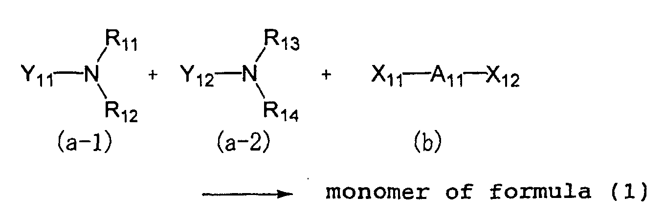
It is noted that Y11, Y12, R11 to R14, and A11 in the
above scheme are as defined for formula (1). Reference is
made to the example in which X11 and X12 are halogen atoms.
First, acrylic amine compounds (a-1, a-2) are reacted
with a dihalogen compound (b) to form a monomer of formula
(1) containing a quaternary ammonium salt and having an
acrylic unsaturated group at either end. In this stage,
the amount of acrylic amine compounds added is at least 2
moles, especially 2.0 to 3.0 moles per mole of the
dihalogen compound.
The reaction is carried out by stirring the reactants
in an aprotic polar solvent such as acetonitrile or dioxane
at about 50°C for several days. If the reactants are
subject to reflux in an alcohol such as methanol,
isopropanol, methoxyethanol or 2-ethoxyethanol as the
solvent, ester interchange can occur, failing to produce
the desired diacrylic quaternary ammonium salt. Therefore,
the alcoholic solvents which can trigger ester interchange
reaction are not suitable.
At the end of reaction, acetone or the like is added
to the reaction solution whereby the desired quaternary
ammonium salt precipitates. The white precipitate thus
obtained is filtered out. Acetone washing and drying
yields the end compound.
The compounds used in introducing ethylenically
unsaturated reactive groups, preferably acrylic unsaturated
reactive groups into the monomer of formula (1) at both
ends thereof are not critical as long as they have
ethylenically unsaturated reactive groups, preferably
acrylic unsaturated reactive groups such as acryloyloxy,
methacryloyloxy, acryloylamino, methacryloylamino,
diacryloylamino, and dimethacryloylamino groups. The
preferred compounds are dialkylaminoethyl acrylates or
methacrylates and dialkylaminoethyl acrylate or
methacrylate amides. Illustrative examples are given
below:
Examples of the dihalogen compounds to be reacted
therewith include 1,3-dichloropropane, 1,4-dichlorobutane,
1,5-dichloropentane, 1,6-dichlorohexane, 1,8-dichlorooctane,
1,10-dichlorodecane, 1,12-dichlorododecane,
1,3-dibromopropane, 1,4-dibromobutane, 1,5-dibromopentane,
1,6-dibromohexane, 1,8-dibromooctane, 1,10-dibromodecane,
and 1,12-dibromododecane.
The molecular weight of the monomer of formula (1) is
not critical although it is generally 650 or lower when the
preferred A11 or the like is taken into account. The lower
limit is not critical although it is generally about 370.
Described below is the monomer of formula (2) which
is used along with the monomer of formula (1) to produce
the copolymer contained in the humidity sensitive thin film
according to the first embodiment of the invention.
Formula (2) is described.

In formula (2), Y1 to Y6 each are a monovalent group,
and at least one of Y1 to Y6 is a group terminated with an
ethylenically unsaturated reactive group. Exemplary groups
include acryloyloxy, methacryloyloxy, acryloylamino,
methacryloylamino, vinyl, allyl, diallylmethyl, allyloxy,
diacryloylamino and dimethacryloylamino groups as well as
groups having the foregoing groups introduced therein.
Examples of the groups, other than the group
terminated with an ethylenically unsaturated reactive
group, represented by Y1 to Y6 include alkyl groups,
alkenyl groups and halogen atoms. Examples of the alkyl
and alkenyl groups are as exemplified for R1 or the like in
formulae (3) and (4) which are preferred among formula (2),
and will be described later in conjunction with formulae
(3) and (4). The halogen atoms include chlorine, bromine,
iodine, etc. Any two or more of Y1 to Y5, A and portions
thereof, or any two or more of Y4 to Y6, B and portions
thereof, taken together, may form a ring with the nitrogen
(N) atom. The ring thus formed is the same as the ring
formed by R1 or the like in formulae (3) and (4), and will
be described later.
As indicated above, the monomer of formula (2) may
have at least one ethylenically unsaturated reactive group
and most often, preferably about two such groups.
The monovalent groups represented by Y2 to Y5 each
may contain a chain for linking recurring units in the
molecular structure represented by formula (2) and in this
case, the recurring units in formula (2) may be the same or
different.
It is noted that A, B, n, X1 - and X2 - in formula (2)
have the same meaning as those in formulae (3) and (4) and
will be described all together in conjunction with formulae
(3) and (4).
Among the monomers of formula (2), monomers of
formulae (3) and (4) are preferred. Formulae (3) and (4)
are described below.

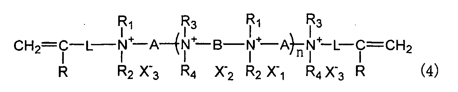
In formulae (3) and (4), A and B each are a divalent
group.
The divalent group represented by A is preferably an
alkylene, alkenylene or arylene group or a mixture thereof.
These groups may have substituents, for example, hydroxyl
groups, alkyl groups such as methyl, and carbamoyl groups.
The alkylene groups preferably have 1 to 20 carbon
atoms in total and if substituted, they preferably have 1
to 5 hydroxyl groups.
The alkenylene groups preferably have 2 to 10 carbon
atoms in total.
The arylene groups preferably have 6 to 20 carbon
atoms in total.
When the divalent group is a mixture of these groups,
the mixture preferably has 3 to 20 carbon atoms in total.
Illustrative, preferred examples of A include
-(CH2)m- wherein m is an integer of 1 to 20, -CH2CH=CH-CH2-,
-CH2-CH(OH)-CH2-, -CH(CH3)-CH2-CH2-, -C6H4-C6H4-, and -C6H4-CH(OH)-C6H4-.
Among others, A is preferably an unsubstituted
alkylene group, especially straight -(CH2)m- wherein m is
preferably about 3 to about 16 although m is determined
depending on B, X1 -, X2 - or the type and copolymerization
ratio of the monomer of formula (1) to be copolymerized
therewith.
The divalent groups represented by B include alkylene
groups, alkylene groups which are separated by at least one
of oxy (-O-) and carbonyl (-CO-), alkenylene groups,
arylene groups, and mixtures thereof, which may be
substituted with hydroxyl groups or alkenyl groups such as
vinyl.
The alkylene groups preferably have 1 to 20 carbon
atoms in total and if substituted, they preferably have 1
to 5 hydroxyl groups. When alkylene groups are separated
by -O- and/or -CO-, the preferred number of such
intervening groups is 1 to 5 in total.
The alkenylene groups preferably have 2 to 10 carbon
atoms in total. The arylene groups preferably have 6 to 20
carbon atoms in total. When the divalent group is a
mixture of these groups, the mixture preferably has 3 to 20
carbon atoms in total.
Illustrative, preferred examples of B include
-(CH2)m- wherein m is an integer of 1 to 20, -(CH2)2-CH(OH)-CH2-,
-CH2-CH(OH)-CH2-, -CH2-CH=CH-CH2-, -CH2-CH(CH=CH2)-,
-(CH2-CH2-O)2-(CH2)2- -CH2-(CO)-CH2-, and -CH2-C6H4-CH2-.
Among others, B is preferably an unsubstituted
alkylene group, especially straight -(CH2)m- wherein m is
preferably about 3 to about 16 although m is determined
depending on A, X1 -, X2 - or the type and copolymerization
ratio of the monomer of formula (1) to be copolymerized
therewith.
Each of R1, R2, R3 and R4 is an alkyl or alkenyl
group.
The alkyl groups represented by R1 to R4 are
preferably those of 1 to 10 carbon atoms, and may have
substituents, but are preferably unsubstituted. Preferred
examples include methyl, ethyl, propyl and butyl.
The alkenyl groups represented by R1 to R4 are
preferably those of 2 to 10 carbon atoms, and may have
substituents, but are preferably unsubstituted. Preferred
examples include vinyl, allyl, propenyl and butenyl.
R1 and R2, R1 and A or a portion of A, R2 and A or a
portion of A, R3 and R4, R3 and A or a portion of A, R4 and
A or a portion of A, R1 and R3 or R4, or R2 and R3 or R4,
taken together, may form a ring with the nitrogen (N) atom.
These rings are preferably 5- or 6-membered rings,
especially 6-membered nitrogenous heterocycles and may even
bridged rings. Preferred examples of the nitrogenous
heterocycles include pyridine, 1,4-azabicyclo[2.2.2]octane,
piperidine, piperazine and pyrazine rings, which may be
substituted with carbamoyl or other groups.
In formula (3), R5 and R6 each are an alkyl or
alkenyl group. Of these, alkyl groups are preferred, with
those of 1 to 10 carbon atoms being especially preferred.
The alkyl groups may have substituents, but are preferably
unsubstituted. Methyl and ethyl are preferred groups.
Examples of the alkenyl groups represented by R5 and R6 are
as exemplified for R1 to R4.
In formulae (3) and (4), L is a divalent group.
Preferred examples of L in formula (3) include -COO(CH2)2-,
-CONH(CH2)3-, and -(CH2)m- wherein m is an integer of 1 to
20. Preferred examples of L in formula (4) include
-OCH2CH2-, -(CH2)m- wherein m is an integer of 1 to 20,
-COO(CH2)2-, -COOCH2CH(OH)CH2-, and -CH2-C6H4- (p- or m-form).
It is noted that in formula (3), any two or three of
R5, R6 and L, suitably taken together, may form a pyridine
or analogous ring with the nitrogen (N) atom.
In formulae (3) and (4), R is hydrogen or an alkyl
group, and preferably hydrogen or methyl.
In formulae (3) and (4), X1 - and X2 - are anions,
preferably halide ions, for example, chloride, bromide and
iodide ions, with chloride and bromide ions being
preferred. X1 - and X2 - are generally the same, but may be
different from each other. In formula (4), X3 - is an anion.
For two X3 - in formula (4), the identical symbol is used in
accordance with the synthesis scheme to be described later,
and they are generally the same, but may be different from
each other. Illustrative examples and preferred examples
of X3 - are the same as those of X1 - and X2 -. Most often, X1 -,
X2 - and X3 - are the same. The letter n is a number of 2 to
5,000.
The monomers of formulae (2), (3) and (4) are
regarded as polymers comprising specific recurring units
and having a number average molecular weight Mn of about
1,000 to about 1,000,000.
The monomer of formula (3) can be synthesized
according to the scheme shown below. Reference is made to
the example wherein X1 - and X2 - are halide ions. The symbols
used in the scheme are as defined previously.

First, a diamine compound is reacted with a dihalogen
compound to form an intermediate polymer I having a
quaternary ammonium salt and terminal groups which are
halogen. At this stage, reaction may be carried out under
such conditions that 1.0 to 2.0 moles of the dihalogen
compound is available per mole of the diamine compound. In
order to ensure that the terminal groups of intermediate
polymer I be halogen, the dihalogen compound may be added
in two divided portions. It is recommended herein that the
first portion of the dihalogen compound be 1 to 1.3 moles
per mole of the diamine compound, and the balance be added
as the second portion.
The reaction is carried out in a nonaqueous solvent
such as methanol, isopropanol, methoxyethanol or 2-ethoxyethanol
at a reflux temperature or a temperature of
about 100°C for about 5 to about 100 hours.
Next, a compound having an ethylenically unsaturated
reactive group, A, is reacted with the intermediate polymer
I for introducing ethylenically unsaturated reactive groups
into the intermediate polymer I at both ends, to thereby
form the monomer of formula (3). The reaction of this
stage may be carried out subsequent to the reaction of the
preceding stage. Specifically, the compound having an
ethylenically unsaturated reactive group, A, in a
substantially equimolar amount to the dihalogen compound,
is added to the reaction solution whereupon reaction is
carried out at a temperature of about 15 to about 100°C for
about 10 to about 150 hours.
Thereafter, the reaction solution is added dropwise
to a solvent such as acetone or ethyl acetate whereupon a
precipitate forms. The precipitate is collected by
filtration and purified, obtaining the end compound.
On the other hand, the monomer of formula (4) can be
synthesized according to the scheme shown below. Reference
is made to the example wherein X1 - and X2 - are halide ions.
The symbols used in the scheme are as defined previously.
It is preferred that X3 - be a halide ion as well.

First, a diamine compound is reacted with a dihalogen
compound to form an intermediate polymer II having a
quaternary ammonium salt and terminal groups which are
amino groups. At this stage, reaction may be carried out
under such conditions that 1.1 to 2.0 moles of the diamine
compound is available per mole of the dihalogen compound.
Reaction conditions other than this are the same as used
above in the formation of intermediate polymer I. The same
means as above may be taken to ensure that the terminal
groups be amino groups.
Next, a compound having an ethylenically unsaturated
reactive group, B, is reacted with the intermediate polymer
II for introducing ethylenically unsaturated reactive
groups into the intermediate polymer II at both ends, to
thereby form the monomer of formula (4). The reaction of
this stage may be carried out in the same manner as used
for the monomer of formula (3).
The monomer of formula (3) or (4) is obtained by
reaction of a diamine compound with a dihalogen compound.
Any desired diamine compound and dihalogen compound may be
used herein as long as they can follow the reaction
according to the above scheme. It is noted that the
monomers and intermediate polymers are typically obtained
as a mixture of oligomers having a degree of polymerization
(n) of about 2 to 20 and polymers having a degree of
polymerization (n) of more than 20.
Preferred examples of the diamine compound are given
below.




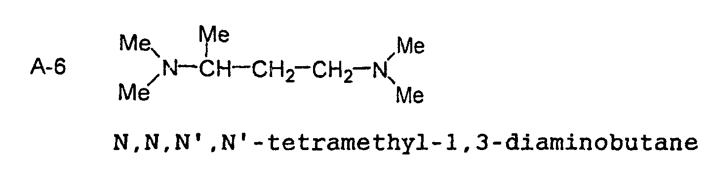

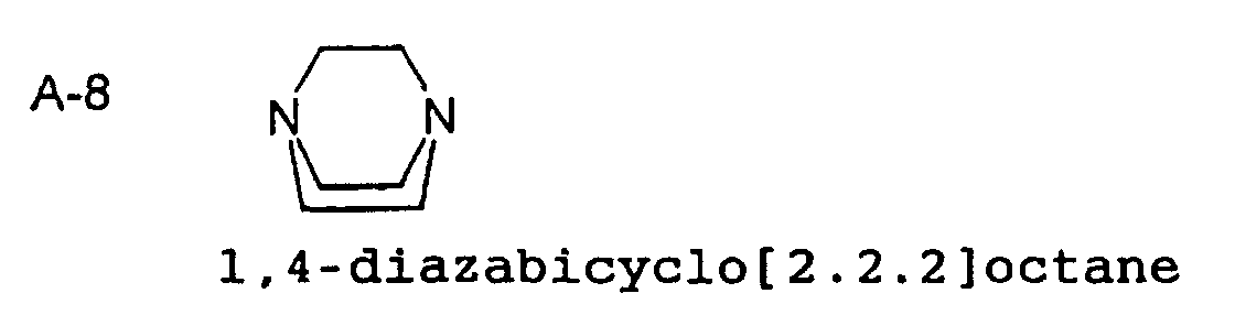
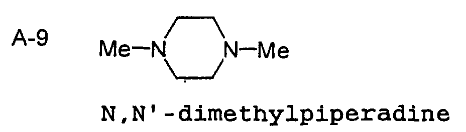





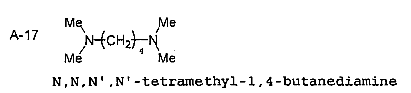
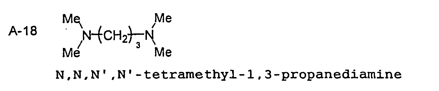

Preferred examples of the dihalogen compound are
given below.



B-4 X―CH2 ―CH=CH―CH2 ―X

B-6 X―CH2 ―CH2 ―O―CH2 CH2 ―O―CH2 ―CH2 ―X
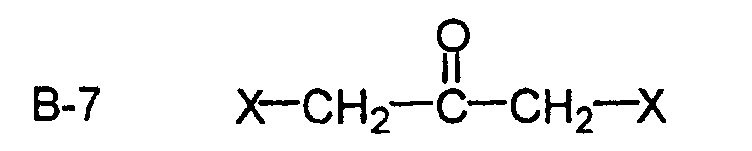


In these examples, X is a halogen atom, with chlorine
and bromine atoms being preferred.
Examples of the intermediate polymers to the monomers
of formulae (3) and (4) are shown below as polymers
resulting from combinations of the diamine and dihalogen
compounds illustrated just above. Note that numerical
values in the parentheses represent a molar ratio.
The compounds A and B used in introducing
ethylenically unsaturated reactive groups into intermediate
polymers I and II at both ends are not critical as long as
they have an ethylenically unsaturated reactive group such
as an acryloyloxy, methacryloyloxy, acryloylamino,
methacryloylamino, vinyl, allyl, diallylmethyl, allyloxy,
diacryloylamino, and dimethacryloylamino group. Where
intermediate polymers I and II as produced already have an
ethylenically unsaturated reactive group at an end as in
the case of, for example, polymers (10), (11) and (13),
they may be used as the monomer in the practice of the
invention without further reaction.
Preferred examples of compound A used in combination
with intermediate polymer I are given below.
E-1 CH2 =CHCO2 C2 H4 NMe2
E-2 CH2 =CHCONHC3 H6 NMe2


Preferred examples of compound B used in combination
with intermediate polymer II are given below.
F-1 CH2 =CHOCH2 CH2 X


In the above formulae, X is a halogen atom, and
preferably chlorine and bromine.
The copolymer according to the first embodiment of
the invention is obtained by applying a mixed solution of
the monomer of formula (1), the monomer of formula (2) and
a photo-polymerization initiator onto a substrate to form a
coating, drying and irradiating UV radiation for
polymerization. For each monomer type, one or more
monomers may be used.
The mixing ratio of the monomer of formula (1) to the
monomer of formula (2) is determined in accordance with the
intrinsic impedance of each monomer, the degree of
crosslinking upon mixing, and the shape of electrodes on
the substrate. Therefore, the mixing ratio differs case by
case and is not determined within a certain range.
Usually, the molar ratio of the monomer of formula (1) to
the monomer of formula (2) is from about 10:1 to about
1:10.
As the polymerization initiator, any of commercially
available polymerization initiators such as benzophenone
derivatives may be used.
In the first embodiment of the invention,
polymerization is preferably carried out by irradiation of
UV radiation although polymerization may also be induced by
heating and preferably by heating followed by UV
irradiation.
The humidity sensitive thin film obtained by
copolymerization reaction of quaternary ammonium salt
monomers of formulae (1) and (2), preferably difunctional
ammonium salts is not only very robust due to three-dimensional
crosslinking, but also the quaternary ammonium
salt has an ionene structure of the so-called backbone type
and does not have a structure with a high degree of freedom
like the pendant type structure. Therefore, the film
maintains a humidity sensitive curve with minimal
hysteresis.
While the humidity sensitive thin film according to
the first embodiment of the invention contains a
crosslinked product of the copolymer resulting from
reaction of the monomer of formula (1) with the monomer of
formula (2) as indicated above, formation of the humidity
sensitive thin film is preferably carried out by the
following procedure.
A coating solution containing the monomer of formula
(1) and the monomer of formula (2) is prepared. In this
regard, one monomer of formula (1) and one monomer of
formula (2) are used in most cases although two or more
different monomers may be used for each type or for either
one of the two types. The monomers used herein are
preferably those having a halide ion as the anion, more
preferably a chloride or bromide ion. It is especially
preferred to use at least one monomer having a chloride
ion.
The coating solution is an aqueous solution or an
alcoholic or organic solvent solution or a mixture thereof
which contains the monomers in a predetermined ratio and in
a concentration of 1 to 10% by weight. When the copolymer
is to be later crosslinked by exposure to radiation,
especially UV radiation, a photo-polymerization initiator
(e.g., water-soluble benzophenone compound) is preferably
added in a concentration of 0.03 to 0.7% by weight.
Although the humidity sensitive thin film obtained
according to the first embodiment of the invention does not
peel from the substrate because the swell of the film is
reduced as compared with conventional films, the following
treatment may be further carried out in order to ensure the
adhesion to the substrate and provide higher water
resistance.
An acrylic silane coupling agent which is an acrylic
monomer having a functional group (alkoxysilyl group)
capable of reacting with the substrate or electrode, such
as γ-methacryloxypropyltrimethoxysilane is copolymerized.
In an alternative procedure, the substrate (usually
electrode-bearing substrate) is treated with an acrylic
silane coupling agent and heated, then a solution
containing the monomer of formula (1) and the monomer of
formula (2) is applied, dried, and copolymerized. In the
former procedure, after the humidity sensitive thin film is
formed by copolymerization, it is preferably held at a high
humidity (i.e., in the presence of water vapor) for
improving adhesion.
Convenient examples of the acrylic silane coupling
agent include γ-methacryloxypropylmethyldimethoxysilane, γ-methacryloxypropyltrimethoxysilane,
γ-methacryloxypropylmethyldiethoxysilane
and γ-methacryloxypropyltriethoxysilane,
which are commercially available as KBM502, KBM503,
KBE502 and KBE503, respectively, from Shin-Etsu Chemical
Co., Ltd.
The insulating substrate used herein may be formed of
any desired material which has on the surface functional
groups such as hydroxyl groups to ensure adhesion to the
humidity sensitive thin film and is electrically
insulating. Use may be made of glass, plastics such as
phenolic resins and epoxy resins, ceramics and metals
coated with resins having hydroxyl or similar groups. The
electrodes may be made of any conventional electrode
material. For example, they are formed by screen printing
low resistance paste containing Au or RuO2 and optionally
glass frit, followed by high temperature firing. It is
noted that in the case of oxide electrodes such as RuO2,
hydroxyl or similar functional groups on their surface
contribute to an improvement in adhesion to the humidity
sensitive thin film.
In the first embodiment of the invention, instead of
the above-mentioned method using the acrylic monomer having
an alkoxysilyl group, it is acceptable to use a method
involving removing contaminants and/or oxides on the
uppermost surface layer of the insulating substrate by
physical means, then forming a humidity sensitive thin film
for thereby improving the adhesion between the humidity
sensitive thin film and the substrate. The detail of this
method will be described later.
Where treatment resorts to physical means, the
treatment alone is sufficient because it is possible to
provide satisfactory adhesion to the humidity sensitive
thin film. However, a combined method is acceptable in
which the interdigital electrode-bearing substrate after
the treatment is further treated with the aforementioned
acrylic monomer having an alkoxysilyl group (e.g., acrylic
silane coupling agent).
In the first embodiment of the invention, using the
coating solution, preferably by coating, a humidity
sensitive thin film is formed on the insulating substrate
having electrodes borne thereon as indicated above. Any
desired coating technique may be used as long as a
predetermined amount can be applied to the insulating
substrate. Various techniques such as dipping, dispensing,
brush coating, gravure coating, screen printing, and spin
coating techniques are useful. A choice may be made
depending on the overall procedure and the type and
application of a final product.
After the coating is formed in this way, it is dried
and/or thermally crosslinked at a temperature of about 15
to 100°C for about 3 to 15 minutes and then crosslinked
with radiation. Crosslinking by exposure to radiation is
preferably by exposure to UV radiation. It is noted that
crosslinking progresses along with copolymerization.
Crosslinking by exposure to UV radiation may be
carried out by any well-known technique. Often UV
radiation having an intensity of at least about 80 mW/cm2
is irradiated in an exposure of about 200 to 2,500 mJ/cm2.
Conventional light sources such as mercury lamps may be
used as the UV source.
The humidity sensitive thin film as crosslinked
preferably has a thickness of about 0.5 to 10 µm,
especially about 3 to 10 µm. Film thickness outside this
range is undesirable because a thicker film would be slow
in response of its electric resistance to humidity whereas
a thinner film would produce lower outputs in the low
humidity region and be less resistant to gas.
In the second embodiment of the present invention,
the humidity sensitive thin film contains a crosslinking
copolymer of a monomer of formula (1) with an acrylic
monomer having an alkoxysilyl group. Due to reaction of
hydroxyl or other functional groups on the substrate
surface and/or electrode surface with the alkoxysilyl
groups within the molecule, the humidity sensitive thin
film is bound to the substrate and electrode.
The monomer of formula (1) used herein is the same as
used in the humidity sensitive thin film according to the
first embodiment of the invention, the divalent group
represented by A11 in formula (1) is as defined previously,
and preferably -(CH2)m- wherein m is an integer of 1 to 20.
On the other hand, the acrylic monomer having an
alkoxysilyl group to be copolymerized with the monomer of
formula (1) is a monomer having an acrylic unsaturated
reactive group, with no other particular limits being
imposed thereon. Methacrylic monomers are preferred.
Any alkoxysilyl groups are useful as long as they can
react with functional groups on the substrate and/or
electrode surface such as hydroxyl groups on the surface of
an alumina substrate or oxide electrodes. Those
alkoxysilyl groups are preferred in which the alkoxy moiety
has 1 to 5 carbon atoms in total, and especially the alkoxy
group is methoxy or ethoxy. Further, the number of alkoxy
groups bonding to Si is preferably 2 or 3, and the groups,
other than the acrylic unsaturated reactive group-bearing
group and alkoxy group, bonding to Si are alkyl groups or
the like, preferably having 1 to 5 carbon atoms, and
especially methyl.
Convenient examples of the acrylic monomer having an
alkoxysilyl group include γ-methacryloxypropylmethyldimethoxysilane,
γ-methacryloxypropyltrimethoxysilane, γ-methacryloxypropylmethyldiethoxysilane
and γ-methacryloxypropyltriethoxysilane,
which are commercially available as
KBM502, KBM503, KBE502 and KBE503, respectively, from Shin-Etsu
Chemical Co., Ltd.
It is possible to form a humidity sensitive thin film
by dissolving the monomer of formula (1) in methanol or
ethanol, applying the solution onto electrodes, and
effecting polymerization by exposure to UV radiation. To
ensure adhesion to the substrate and achieve high water
resistance, in the second embodiment of the invention, the
monomer is copolymerized with an acrylic silane coupling
agent monomer having a functional group (alkoxysilyl group)
capable of reacting with the substrate and electrodes, such
as γ-methacryloxypropyltrimethoxysilane. Alternatively,
after the substrate (often, electrode-bearing substrate) is
treated with an acrylic silane coupling agent, the monomer
of formula (1) is coated and polymerized. In either
procedure, a copolymer of the monomer of formula (1) with
the acrylic silane coupling agent monomer forms.
The ratio of the monomer of formula (1) to the silane
coupling agent monomer is preferably between about 1:1 and
about 1:0.01 in molar ratio. Too large an amount of the
silane coupling agent monomer may degrade the humidity
sensing function and impede low-humidity response. Too
small an amount may lead to insufficient adhesion to the
substrate and poor water resistance.
Synthesis of the copolymer in the humidity sensitive
thin film is preferably carried out simultaneous with
formation of the humidity sensitive thin film as follows.
A mixed solution containing the monomer of formula
(1), the silane coupling agent monomer and a photo-polymerization
initiator is applied onto a substrate to
form a coating, dried and irradiated with UV radiation for
polymerization. As the polymerization initiator,
commercially available initiators such as benzophenone
derivatives may be used. Then the coating is held at a
high humidity (i.e., in the presence of water vapor) to
promote reaction of hydroxyl or other functional groups on
the substrate surface and/or electrode surface with
alkoxysilyl or silanol groups, establishing a firm bond to
the substrate. The firm bond resulting from reaction with
functional groups on the substrate surface or electrode
surface is confirmed by the finding that neither film
separation nor output drops occur after water immersion.
Alternatively, after the substrate (often electrode-bearing
substrate) is treated with the silane coupling agent, the
monomer of formula (1) is coated and polymerized, with
equivalent results.
The humidity sensitive thin film obtained by reaction
of the quaternary ammonium salt monomer of formula (1),
preferably difunctional ammonium salt with the acrylic
silane coupling agent is not only very robust due to three-dimensional
crosslinking, but also the quaternary ammonium
salt has an ionene structure of the so-called backbone type
and does not have a structure with a high degree of freedom
like the pendant type structure. Therefore, the film
maintains a humidity sensitive curve with minimal
hysteresis.
It is also preferred that chloride ions account for
at least 30 mol%, especially at least 50 mol% of the halide
ions that constitute the quaternary ammonium salt in the
crosslinking copolymer. The inclusion of chloride ions
facilitates movement of ions so that a fully linear
response may be developed even in a low-humidity region of
RH 0 to 50%.
Further, after covalent bonds are established by
reaction of the substrate and/or electrode with alkoxysilyl
or silanol groups, the separation of the film from the
substrate is prevented and water resistance is
significantly improved. Since the separation of the film
from the substrate is prevented, the film thickness can be
increased so that resistance to gases such as Cl2, NOx,
SOx, H2S, HCl and NH3 is improved. Additionally, the
humidity sensitive thin film according to the invention
does not lose gloss in the presence of a vapor of alcohol,
acetone or hexane and is thus highly solvent resistant.
While the humidity sensitive thin film in the second
embodiment of the invention contains a crosslinked product
of a copolymer resulting from reaction of the monomer of
formula (1) with the acrylic monomer having an alkoxysilyl
group as indicated above, formation of the humidity
sensitive thin film is preferably carried out by the
following procedure.
A coating solution containing the monomer of formula
(1) and the acrylic monomer having an alkoxysilyl group is
prepared. In this regard, one monomer of formula (1) and
one acrylic monomer having an alkoxysilyl group are used in
most cases although two or more different monomers may be
used for each type or for either one of the two types.
The coating solution is an aqueous solution or an
alcoholic or organic solvent solution or a mixture thereof
containing the monomers in a predetermined ratio and in a
concentration of 1 to 10% by weight. When the copolymer is
to be later crosslinked by exposure to radiation,
especially UV radiation, a photo-polymerization initiator
(e.g., water-soluble benzophenone compound) is preferably
added in a concentration of about 0.03 to 0.7% by weight.
In the second embodiment of the invention, using the
coating solution, preferably by coating, a humidity
sensitive thin film is formed on the insulating substrate
having electrodes borne thereon as indicated above. Any
desired coating technique may be used as long as a
predetermined amount can be applied to the insulating
substrate. Various techniques such as dipping, dispensing,
brush coating, gravure coating, screen printing, and spin
coating techniques are useful. A choice may be made
depending on the overall procedure and the type and
application of a final product. It is noted that a
solution to which all the components have been added may be
used as the coating solution, while a procedure of first
applying a coating solution of the acrylic monomer having
an alkoxysilyl group and then applying a coating solution
of the monomer of formula (1) is also acceptable as
indicated above.
After the coating is formed in this way, it is dried
and/or thermally crosslinked at a temperature of about 15
to 100°C for about 3 to 15 minutes and then crosslinked
with radiation. Crosslinking by exposure to radiation is
preferably by exposure to UV radiation.
Crosslinking by exposure to UV radiation may be
carried out by any well-known technique. Often UV
radiation having an intensity of at least about 50 mW/cm2
is irradiated in an exposure of about 200 to 2,500 mJ/cm2.
Conventional light sources such as mercury lamps may be
used as the UV source.
The insulating substrate used in the second
embodiment may be formed of any desired material which has
on the surface functional groups such as hydroxyl groups to
ensure adhesion to the humidity sensitive thin film and is
electrically insulating. Use may be made of glass,
plastics such as phenolic resins and epoxy resins, ceramics
and metals insulation coated with resins having hydroxyl or
similar groups. The electrodes may be made of any
conventional electrode material. For example, they are
formed by screen printing low resistance paste containing
Au or RuO2 and optionally glass frit, followed by high
temperature firing. It is noted that in the case of oxide
electrodes such as RuO2, hydroxyl or similar functional
groups on their surface contribute to an improvement in
adhesion to the humidity sensitive thin film.
In the second embodiment, when the insulating
substrate is treated with the acrylic monomer having an
alkoxysilyl group as indicated above, this treatment is
carried out on the insulating substrate on which electrodes
(preferably interdigital electrodes) have been arranged.
In the third embodiment of the present invention
wherein contaminants and/or oxides on the uppermost surface
layer of the insulating substrate are removed by physical
means before a humidity sensitive thin film is formed, the
humidity sensitive thin film can be comprised of a polymer
obtained from the monomer of formula (1) without using the
monomer of formula (2) and the acrylic monomer having an
alkoxysilyl group.
In this embodiment, formation of the humidity
sensitive thin film can be carried out in the same manner
as formation of the humidity sensitive thin film in the
foregoing embodiments, using a coating solution containing
the monomer of formula (1), and without using the monomer
of formula (2) and the acrylic monomer having an
alkoxysilyl group.
The treatment by physical means is carried out on the
insulating substrate on which electrodes, preferably
interdigital electrodes have been arranged.
The insulating substrate bearing a pair of
interdigital electrode to be treated by physical means may
be formed of any desired material which is not chemically
reactive with the humidity sensitive thin film and is
electrically insulating. Use may be made of glass,
plastics, ceramics and metal plates coated with insulating
material. In particular, alumina is preferred for
mechanical strength, insulation and stability.
Hereinafter, reference is made to the preferred use
of an alumina substrate.
The surface layer of the insulating substrate bearing
a pair of interdigital electrodes (to be referred to as
interdigital electrode-bearing substrate) have much
contaminants, adsorbed gases and organic matter adsorbed
thereto during its preparation and storage. The uppermost
surface layer of the alumina substrate is covered with
oxides of the substrate itself or the like.
The contaminants, adsorbed gases and organic matter,
except oxides, which are taken to the interdigital
electrode-bearing substrate from the exterior as mentioned
above, are designated together as contaminants, whereas
oxide contaminants and the material of the insulating
substrate itself are designated together as oxide.
More particularly, for example, organic matter
floating in the surrounding atmosphere and residues of
chemicals and additives used during preparation built up on
the substrate. They, combined with the oxide of the
substrate itself, serve to lower the wettability of the
interdigital electrode-bearing substrate so that when a
solution of the monomer of formula (1) is applied thereto,
the solution may not spread over, and after polymerization,
the humidity sensitive thin film remains less adherent to
the substrate.
Therefore, in the third embodiment of the invention,
contaminants and/or oxides on the uppermost surface layer
are removed by treatment by physical means prior to the
application of a solution of the monomer of formula (1).
Referring to an alumina substrate as a typical
example, the uppermost surface layer occupies a region
extending from the surface (including the uppermost surface
layer) of the substrate to a depth of about 1 nm when
contaminants are present on the surface, provided that
pores are neglected. The removal of contaminants and
oxides from the uppermost surface layer by physical means
can be confirmed in terms of surface wettability. Most
often, the contact angle with water becomes close to 0°.
Removal treatment is carried out on contaminants and
preferably on sub-surface layers of the electrodes and the
substrate themselves (a region extending from the surface
of the object to a depth of about 1 nm). It is therefore
preferred to remove both contaminants and oxides. It is
noted that excessive removal of the sub-surface layers of
the electrodes and the substrate themselves is undesirably
accompanied with configuration changes.
As the treatment by physical means, plasma flame
treatment, UV/ozone treatment, excimer UV treatment, corona
treatment, electron beam treatment, laser treatment,
sputtering treatment, and plasma treatment may be used. Of
these, plasma treatment is preferred because of minimized
damage to the insulating substrate and low cost. UV/ozone
treatment is applicable to some interdigital electrode-bearing
substrates because of low cost, but when applied to
alumina substrates, coloring is often found at the end of
treatment. Coloring can be prevented by selecting
treatment conditions.
Described below is the plasma treatment which is
preferably employed in the third embodiment of the
invention.
As previously described in the 'Operation' section,
the organic matter-removing effect and the surface
modifying effect that oxygen plasma exerts and the metal
oxide-reducing effect that hydrogen plasma exerts are
effective. Preferably, oxygen plasma treatment is
performed alone, or oxygen plasma treatment is followed by
hydrogen plasma treatment. From the standpoint of ease of
operation, a plasma treatment with the aid of an inert gas
introduced is also preferred.
The plasma treatment may be carried out under any
conditions such as vacuum, inert gas and atmospheric
pressure, as long as such conditions are relatively low
temperature plasma conditions which do not cause damages to
the interdigital electrode-bearing substrate. The
apparatus used may be selected in accordance with treatment
conditions. Among others, conditions in an inert gas and
under atmospheric pressure are appropriate because a simple
apparatus can be used. However, it is customary to carry
out plasma treatment in vacuum while introducing oxygen or
hydrogen as indicated above.
The plasma used in either of these methods is
generated at a power supply frequency of several kHz to
several hundred MHz, and the power is adjusted in
accordance with the plasma generating conditions. Where
the interdigital electrode-bearing substrate is alumina,
satisfactory results are obtained by treating it at a highfrequency
power in the range of 50 to 1,000 W for a time of
2 seconds to 10 minutes.
Following the plasma treatment of the interdigital
electrode-bearing substrate, a solution of the monomer of
formula (1) is applied to the substrate. The duration from
the plasma treatment to the monomer coating is from 24 to
96 hours when the substrate is held in vacuum, and the
monomer coating is preferably performed immediately or
within 24 hours after the plasma treatment when the
substrate is held in atmospheric pressure. When the
substrate is held under inadequate storage conditions, the
duration within which the surface state is maintained sound
becomes short. It is then desired to carry out coating
immediately after the plasma treatment in a continuous
manner.
Where treatment resorts to physical means, the
treatment alone is sufficient because it is possible to
provide satisfactory adhesion to the humidity sensitive
thin film. However, a combined method is acceptable in
which the interdigital electrode-bearing substrate after
the treatment is further treated with the aforementioned
acrylic monomer having an alkoxysilyl group (e.g., acrylic
silane coupling agent). Likewise, the treatment by
physical means is effectively applicable to the humidity
sensitive thin film comprising the copolymer of the monomer
of formula (2) with the monomer of formula (1) as described
above.
In the second and third embodiments of the invention,
the humidity sensitive thin film as crosslinked preferably
has a thickness of about 0.5 to 10 µm, especially about 3
to 10 µm. Film thickness outside this range is undesirable
because a thicker film would be slow in response of its
electric resistance to humidity whereas a thinner film
would produce lower outputs in the low humidity region and
be less resistant to gas and water.
The method of the invention according to the third
embodiment wherein contaminants and/or oxides on the
uppermost surface layer of the insulating substrate are
removed by physical means before a humidity sensitive thin
film is formed is applicable to not only the humidity
sensitive thin film which is comprised of a polymer
obtained from a monomer of formula (1), but also the
humidity sensitive thin film which is comprised of a
polymer obtained from a monomer having an ethylenically
unsaturated reactive group, preferably a monomer having an
ethylenically unsaturated reactive group and a quaternary
ammonium salt. In the latter case too, the adhesion
between the humidity sensitive thin film and the insulating
substrate is improved.
The polymers of which the humidity sensitive thin
film is formed in the latter case include the
aforementioned copolymers of the monomer of formula (1)
with the monomer of formula (2) and other polymers as will
be described below.
Illustrative are polymers obtained from the monomer
of formula (2), preferably polymers obtained from the
monomer of formula (3) and/or the monomer of formula (4).
In addition to the polymers obtained from the
monomers of formula (1) wherein R11 to R14 are alkyl,
polymers obtained from the monomers of formula (1) wherein
R11 to R14 are hydrogen are also preferred. In these
monomers, it is preferred that at least one of R11 and R12
be alkyl and at least one of R13 and R14 be alkyl. Those
monomers analogous to the monomers of formula (1) can be
synthesized by the same procedure as the monomers of
formula (1).
The compounds used in introducing ethylenically
unsaturated reactive groups, preferably acrylic unsaturated
reactive groups into the foregoing monomers at both ends
thereof are not critical as long as they have ethylenically
unsaturated reactive groups, preferably acrylic unsaturated
reactive groups such as acryloyloxy, methacryloyloxy,
acryloylamino, methacryloylamino, diacryloylamino, and
dimethacryloylamino groups. Illustrative examples are
given below:
In the embodiment wherein treatment is carried out by
physical means, the humidity sensitive thin film may also
be formed of a polymer obtained from a monomer of the
following formula (5) because it has the advantage that a
more number of quaternary ammonium salts serving as
conductivity-providing sites can be introduced, despite the
drawback that some hysteresis is developed.
The monomer of formula (5) is described below.

In formula (5), A21 is a divalent group. R21, R22 and
R23 each are an alkyl group and they may be the same or
different. Y21 is a monovalent group terminated with an
ethylenically unsaturated reactive group. X21 - is an anion.
The divalent group represented by A21 is preferably
an alkylene, alkenylene, arylene (e.g., phenylene),
carbonyl or carbonyloxy group or a mixture thereof. These
groups may have substituents, for example, alkyl groups
such as methyl, and carbamoyl groups.
The alkylene groups preferably have 1 to 20 carbon
atoms in total.
The alkenylene groups preferably have 2 to 10 carbon
atoms in total.
The arylene groups preferably have 6 to 20 carbon
atoms in total.
When the divalent group is a mixture of these groups,
the mixture preferably has 3 to 20 carbon atoms in total.
Illustrative, preferred examples of A21 include
-(CH2)m- wherein m is an integer of 1 to 20, -CH2CH=CH-CH2-,
-CH(CH3)-CH2-CH2-, and -C6H4-C6H4-, with -(CH2)m- wherein m is
an integer of 1 to 20 being especially preferred.
The monovalent groups terminated with an
ethylenically unsaturated reactive group represented by Y21
are preferably vinyl and acrylic, especially acrylic, for
example, groups having an acryloyloxy, methacryloyloxy,
acryloylamino and methacryloylamino group, and preferably
alkylene acrylate or methacrylate groups or alkylene
acrylate or methacrylate amide groups.
The alkyl groups represented by R21 to R23 are
generally unsubstituted ones, but may have substituents,
and preferably contain 1 to 5 carbon atoms in total.
Examples include methyl, ethyl and propyl, with methyl
being especially preferred. R21 to R23 are generally the
same, but may be different from each other.
Any two or more of R21 to R23, Y21, A21 and portions
thereof adjoining the N, taken together, may form a ring
with the nitrogen (N) atom although it is preferred that
they do not form a ring.
The anions represented by X21 - are preferably halide
ions, for example, chloride, bromide and iodide ions.
Chloride and bromide ions are preferred, and chloride ions
are most preferred.
As indicated above, the monomer of formula (5) is
preferably a monofunctional monomer having an acrylic
unsaturated reactive group.
The monomer of formula (5) used herein is obtained as
follows. Illustratively, the monomer of formula (5) is
synthesized according to the following monomer.

It is noted that Y21, A21, R21 to R23 in the above
scheme are as defined for formula (5). Reference is made
to the example in which X21 is a halogen atom.
First, an acrylic amine compound (a) is reacted with
a monohalogen compound (b-1) to form a monomer of formula
(2) containing a quaternary ammonium salt and having an
acrylic unsaturated group as one terminal group. In this
stage, the amount of acrylic amine compound added may be
substantially equimolar, especially 0.95 to 1 mole per mole
of the dihalogen compound.
The reaction is carried out by stirring the reactants
in an aprotic polar solvent such as acetonitrile or dioxane
at about 50 to 70°C for 96 hours. If the reactants are
subject to reflux in an alcohol such as methanol,
isopropanol, methoxyethanol or 2-ethoxyethanol as the
solvent, ester interchange can occur, failing to produce
the desired acrylic quaternary ammonium salt. Therefore,
the alcoholic solvents which can trigger ester interchange
reaction are not suitable.
At the end of reaction, acetone or the like is added
to the reaction solution whereby the desired quaternary
ammonium salt precipitates. The white precipitate thus
obtained is filtered out. Acetone washing and drying
yields the end compound.
The compounds used in introducing an ethylenically
unsaturated reactive group, preferably acrylic unsaturated
reactive group into the monomer of formula (5) at an end
are not critical as long as they have ethylenically
unsaturated reactive groups, preferably acrylic unsaturated
reactive groups such as acryloyloxy, methacryloyloxy,
acryloylamino, methacryloylamino, diacryloylamino, and
dimethacryloylamino groups. The preferred compounds are
dialkylaminoethyl acrylates or methacrylates and
dialkylaminoethyl acrylate or methacrylate amides.
Illustrative examples are given below:
Examples of the monohalogen compounds to be reacted
therewith include chloropropane, chlorobutane,
chloropentane, chlorohexane, chlorooctane, chlorodecane,
chlorododecane, bromopropane, dibromobutane,
dibromopentane, bromohexane, bromooctane, bromodecane, and
bromododecane.
The humidity sensitive thin film may be formed of a
polymer of any one or more of the monomers of formulae (1)
to (5) as well as the aforementioned polymers. More
illustratively, depending on the desired device
performance, a proper choice may be made among polymers of
the backbone type and analogs or inversely, of the pendant
type and analogs, and a proper choice may also be made for
the number of carbon atoms in the backbone or pendant, the
type of counter ion and other factors.
It is noted that in the embodiments of the invention
involving treatment by physical means whereby satisfactory
adhesion to the humidity sensitive thin film is achievable,
the treatment may be combined with treatment with an
acrylic monomer having an alkoxysilyl group (e.g., acrylic
silane coupling agent), though not always necessary. In
this case, the interdigital electrode-bearing substrate
after the treatment may be coated with the acrylic monomer
having an alkoxysilyl group before a humidity sensitive
thin film is formed thereon. Alternatively, the acrylic
monomer having an alkoxysilyl group is added to the coating
solution of the humidity sensitive thin film-forming
monomer.
In all the embodiments of the invention, a water
repellent coating may be formed on the humidity sensitive
thin film in order to preclude any influence of water
droplets depositing thereon and to ensure rapid accurate
humidity measurement. The water repellent coating should
preferably have a contact angle with water of at least 90
degrees, and especially 90 to 130 degrees. To ensure
sufficient penetration of moisture therethrough, the
coating should desirably have a thickness of up to 5 µm,
especially 0.1 to 2 µm. The preferred materials used to
construct the water repellent coating are hydrophobic
polymers, for example, fluoro-polymers such as
polytetrafluoroethylene, olefinic polymers such as
polyethylene and polypropylene, and silicone polymers. The
method of forming the water repellent coating is not
critical and the coating may be formed by dissolving any of
the foregoing material in a suitable solvent (e.g.,
saturated carbon fluoride) and applying the solution.
As long as the humidity sensor device of the
invention includes the above-mentioned humidity sensitive
thin film on an insulating substrate having electrodes
formed thereon, the remaining construction is not critical.
Referring to FIG. 1, there is illustrated one
exemplary arrangement of the humidity sensor device. FIG.
1 is a plan view. As shown in FIG. 1, the humidity sensor
device 1 includes a pair of interdigital electrodes 4 on an
insulating substrate 2. The pair of interdigital
electrodes 4 are disposed on the substrate 2 and
interdigitated with each other to define a gap 5 of a
certain distance therebetween. A humidity sensitive thin
film 3 is formed over the insulating substrate 2 and
interdigital electrodes 4. The interdigital electrodes 4
are provided at one end with electrode tabs 6 to which
leads 7 are connected with solder welds 8. As seen from
the figure, a resist film 9 is formed for preventing
diffusion of the electrode material.
In this arrangement, preferably AC voltage is applied
across the electrodes. Since the humidity sensitive thin
film changes its electrical resistance or impedance in
accordance with the humidity, the output voltage changes
therewith, in terms of which the humidity is detectable.
The applied voltage is typically up to about 12 volts.
Further referring to FIG. 1, the insulating substrate
2 and electrodes 4 used herein are as previously described.
The electrode tabs 6 may be made of any conventional
material which is compatible with the solder 8. For
example, Ag-Pd alloy is printed in a conventional manner
and baked at high temperatures to form the electrode tabs
6. Where Au is used as the electrodes 4, it is preferred
that the resist film 9 of resist or glass is further
provided, as shown in FIG. 1, in order to prevent diffusion
of Au during soldering. No limits are imposed on the
thickness and configuration of the resist film 9 as long as
it is effective for preventing diffusion of Au during
soldering.
The humidity sensor device of the present invention
is not limited to the illustrated embodiment. Any desired
shape or arrangement may be employed.
The gap between a pair of electrodes is typically
about 100 to 500 µm.
Examples are given below together with Comparative
Examples for illustrating the present invention.
First, a monomer of formula (2) was synthesized.
In 20.2 g of methanol, 3.62 g (21.0 mmol) of
N,N,N',N'-tetramethyl-1,12-dodecane diamine was reacted
with 6.92 g (21.1 mmol) of 1,12-dibromododecane at 110°C
for 48 hours. Upon re-precipitation from acetone, 9.04 g
of a white precipitate was obtained. Then, 6.92 g of the
white precipitate was reacted with 3.54 g of
dimethylaminopropyl methacrylamide in methanol at 90°C for
24 hours. Upon reverse re-precipitation from acetone, 5.47
g of a pale yellow precipitate was obtained. It had a
number average molecular weight of about 5,000.
Then, a monomer of formula (1) was synthesized.
In 21.04 g of acrylonitrile were dissolved 11.82 g
(75.2 mmol) of dimethylaminoethyl methacrylate and 4.23 g
(37.4 mmol) of 1,3-dichloropropane. After 0.27 g of 4-methoxyphenol
was added as a polymerization inhibitor,
reaction was effected at 60°C for 120 hours. Upon re-precipitation
from 1000 ml of acetone, 17.52 g of a
quaternary salt was obtained. The yield was 90%.
The monomer of formula (2) and the monomer of formula
(1) thus obtained were weighed in 0.5 g and 0.6 g,
respectively, and 20.9 g of ethyl cellosolve was added
thereto for dissolution. As a polymerization initiator,
0.2% by weight of KAYACURE ABQ (Nippon Kayaku Co., Ltd.)
was added thereto, giving a solution of the humidity
sensitive thin film-forming monomers (coating solution).
The solution was held at 4°C for storage.
Then a humidity sensor device as shown in FIG. 1 was
fabricated. A porous ceramic substrate of alumina was used
as the insulating substrate. Interdigital electrodes 4
were formed on the substrate by screen printing paste
containing RuO2 and glass frit and firing at high
temperature. The gap between the electrodes 4 was about
225 µm.
The interdigital electrode-bearing substrate was
submerged in 100 ml of isopropyl alcohol, immersed therein
for cleaning for 10 minutes while applying ultrasonic
waves, and allowed to stand for drying. This operation was
repeated three cycles.
Immediately after drying, the humidity sensitive thin
film-forming monomer solution was applied to the substrate
by dispensing an aliquot of 2.75 µl per device. By holding
at 25°C for 15 minutes for drying, a coating was formed.
Then the coating was exposed to UV radiation in a nitrogen
atmosphere for one minute for polymerization, yielding a
humidity sensitive thin film. At this point, the exposure
of UV radiation was 1,000 mJ/cm2. The humidity sensitive
thin film had a thickness of about 5 µm.
The humidity sensor device thus fabricated was
evaluated for output and examined by a water resistance
test.
For evaluating the output, a divided flow humidity
generating machine model SRH-1 (manufactured by Shinei
K.K.) was used. The humidity sensor was incorporated in
the circuit described and shown in JP-A 2-123843. The
humidity sensor incorporated in the circuit was set in the
humidity generating machine where the relative humidity was
changed stepwise from a low level to a high level and then
from the high level to the low level both at 25°C. During
the humidity cycling process, the humidity sensor which was
allowed to stand at a selected relative humidity for 30
minutes was measured for output voltage. The selected
relative humidity levels were RH 5%, RH 10%, RH 20%, RH 30%,
RH 40%, RH 50%, RH 60%, RH 70%, RH 80%, RH 90% and RH 95%.
The results are plotted in FIG. 2.
In the water resistance test, the humidity sensor
having undergone output voltage monitoring as mentioned
above was immersed in distilled water for 1 minute, dried
in air, and measured for output voltage again.
Subsequently, the time duration when the humidity sensor
was immersed in distilled water was prolonged to 10 minutes,
30 minutes and 60 minutes whereupon the output voltage was
similarly measured at relative humidity levels of RH 10%,
RH 30%, RH 50%, RH 80% and RH 90% for comparison. The
results are plotted in FIG. 3.
It is evident from FIG. 2 that the inventive humidity
sensor develops a good response curve without hysteresis.
It is evident from FIG. 3 that the inventive humidity
sensor is fully resistant to water.
Additionally, a gas resistance test was carried out.
Gas resistance was tested by measuring outputs of the
humidity sensor at different relative humidity levels,
confirming a linear response thereof, then holding the
sensor under conditions: temperature 40°C and humidity RH
70°C to 80% for 100 hours while flowing nitrogen dioxide
gas, hydrogen chloride gas, ammonia gas, sulfur dioxide gas,
chlorine gas and hydrogen sulfide gas each in a
concentration of 5 ppm, measuring again a humidity-representing
output (%RH) of the humidity sensor at a
preset relative humidity level (%RH), and determining a
maximum change (%RH). The results are shown in Table 1.
| Gas exposed | Maximum change of humidity (%RH) | ||
| Example 1 | Example 3 | Comparative Example 2 | |
| Cl2 | -1.0 | -1.2 | -15.5 |
| H2S | -0.2 | -0.2 | -2.4 |
| SO2 | -3.3 | -3.5 | -29.7 |
| NO2 | -2.1 | -2.6 | -14.1 |
| HCl | -2.5 | -3.1 | -22.3 |
| NH3 | -0.1 | 0.1 | 2.5 |
Minimal changes indicate that the inventive humidity
sensor is fully resistant to gases.
The advantages of the present invention are thus
demonstrated.
An interdigital electrode-bearing alumina substrate
which was prepared by the same procedure as in Example 1
was previously treated with an aqueous acetic acid solution
of 1 wt% γ-methacryloxypropyltrimethoxysilane (KBM503 by
Shin-Etsu Chemical Co., Ltd.), dried, and held at 120°C for
20 minutes for thereby introducing acryloyl groups into the
substrate surface. Thereafter, the substrate was dipped in
the same humidity sensitive thin film-forming monomer
solution as in Example 1, forming a coating. As in Example
1, UV radiation was irradiated to the coating for
polymerization and crosslinking, obtaining a humidity
sensor device.
The humidity sensor device thus fabricated was
subjected to output evaluation and a water resistance test
as in Example 1. The measured results of output are shown
in FIG. 4, and the measured results of the water resistance
test are shown in FIG. 5.
It is evident from FIGS. 4 and 5 that the inventive
humidity sensor develops satisfactory humidity response
performance and water resistance. The water resistance is
improved over Example 1.
Also a gas resistance test was carried out as in
Example 1, obtaining satisfactory results as in Example 1.
First, a monomer of formula (2) was synthesized.
In 23 g of methanol were dissolved 6.30 g (36.6 mmol)
of N,N,N',N'-tetramethyl-1,12-dodecane diamine and 9.62 g
(40.2 mmol) of 1,12-dichlorododecane. The solution was
refluxed in an eggplant-shaped flask. The oil bath
temperature was 110°C at this point. It was observed after
36 hours of reaction that the solution turned white turbid.
After 48 hours, the reaction was stopped, and 40 ml of
methanol was added to the white turbid viscous solution.
Though no insolubles were present, the solution was once
filtered, followed by reverse re-precipitation, obtaining a
white precipitate. The amount of acetone used was 500 ml.
The dry weight was 6.04 g. Subsequently, 5.07 g of the
white precipitate was dissolved in 9 g of methanol.
Dimethylaminopropylmethacrylamide, 2.98 g, was added to the
solution and reaction was effected at an oil bath
temperature of 90°C for 24 hours. The solution was in a
dark orange viscous state. Methanol, 20 ml, was added to
the solution, followed by reverse re-precipitation,
obtaining a pale yellow precipitate. The yield was 2.47 g.
An analysis by gel permeation chromatography (GPC) showed a
number average molecular weight (Mn) of 2734.
Then, a monomer of formula (1) was synthesized.
In 20 ml of acrylonitrile were dissolved 9.63 g (67.2
mmol) of 2-dimethylaminoethyl acrylate and 3.79 g (33.6
mmol) of 1,3-dichloropropane. To the solution was added
0.35 g of 4-methoxyphenol. In an eggplant-shaped flask,
the solution was stirred at 60°C for 5 days (precisely, 128
hours) by means of a magnetic stirrer. It was observed
that the solution remained unchanged after 3 days, but a
white precipitate settled out on the fifth day. The
quaternary salt was completely precipitated out. After the
termination of reaction, 50 ml of methanol was added
thereto for dissolving the white precipitate. Since 0.112
g of insolubles (weighed after drying) was present at this
point, the solution was once filtered. By adding 500 ml of
acetone to the filtrate to effect reverse re-precipitation,
the quaternary salt was completely precipitated out. The
quaternary salt was separated and dried in vacuum,
obtaining the end product. The yield was 5.131 g.
The monomer of formula (2) and the monomer of formula
(1) thus obtained were weighed in 0.3 g and 0.6 g,
respectively, and dissolved in 18 ml of water to prepare an
aqueous solution of about 5% by weight. To the aqueous
solution, 0.2% by weight of KAYACURE ABQ (Nippon Kayaku
Co., Ltd., benzophenone compound) was added as a
polymerization initiator, giving a coating solution
(humidity sensitive thin film-forming monomer solution).
Using the coating solution, a humidity sensor device
1 as shown in FIG. 1 was fabricated. A porous ceramic
substrate of alumina was used as the insulating substrate 2.
Interdigital electrodes 4 were formed on the substrate by
screen printing paste containing RuO2 and glass frit and
firing at high temperature. The gap between the electrodes
4 was about 225 µm.
The coating solution was coated onto the insulating
substrate 2 by dipping and dried at 50°C for 5 minutes,
forming a coating. Then the coating on the electrode side
was exposed to UV radiation in a nitrogen atmosphere for
one minute for crosslinking, yielding a humidity sensitive
thin film 3. At this point, the exposure of UV radiation
was 1,000 mJ/cm2. The humidity sensitive thin film 3 had a
thickness of about 5 µm. The humidity sensor device thus
fabricated was subjected to output evaluation and a water
resistance test as in Example 1. The measured results of
output are shown in FIG. 6, and the measured results of the
water resistance test are shown in FIG. 7.
It is evident from FIG. 6 that the inventive humidity
sensor develops a good response curve without hysteresis.
It is evident from FIG. 7 that the inventive humidity
sensor is fully resistant to water.
Also a gas resistance test was carried out as in
Example 1, with the results shown in Table 1 together with
the results of Example 1. The gas resistance was found
satisfactory.
An interdigital electrode-bearing alumina substrate
which was prepared by the same procedure as in Example 3
was previously treated with an aqueous acetic acid solution
of 1 wt% γ-methacryloxypropyltrimethoxysilane (KBM503 by
Shin-Etsu Chemical Co., Ltd.), dried, and held at 120°C for
20 minutes for thereby introducing acryloyl groups into the
substrate surface. Thereafter, the substrate was dipped in
the same humidity sensitive thin film-forming monomer
solution as in Example 1 forming a coating. As in Example
3, UV radiation was irradiated to the coating for
polymerization and crosslinking, obtaining a humidity
sensor device.
The humidity sensor device thus fabricated was
subjected to output evaluation and a water resistance test
as in Example 1. The measured results of output are shown
in FIG. 8, and the measured results of the water resistance
test are shown in FIG. 9.
It is evident from FIGS. 8 and 9 that the inventive
humidity sensor develops satisfactory humidity response
performance and water resistance. The water resistance is
improved over Example 3.
Also a gas resistance test was carried out as in
Example 1, obtaining satisfactory results as in Example 3.
A monomer of formula (1) was synthesized by the same
procedure as in Example 3 using 5.04 g (25.6 mmol) of
N,N,N',N'-tetramethyl-1,12-dodecane diamine and 9.91 g
(30.2 mmol) of 1,12-dibromododecane as the starting
reactants.
A monomer of formula (2) was synthesized by the same
procedure as in Example 1 using 9.88 g (66.9 mmol) of 2-dimethylaminoethyl
methacrylate and 3.68 g (33.3 mmol) of
1,3-dichloropropane as the starting reactants.
The monomer of formula (2) and the monomer of formula
(1) thus obtained were weighed in 0.1 g and 0.5 g,
respectively, and dissolved in 12 ml of water to prepare an
aqueous solution of about 5% by weight. A humidity sensor
device was fabricated by the same procedure as in Example
1.
The humidity sensor device thus fabricated was
subjected to output evaluation and a water resistance test
as in Example 1. The measured results of output are shown
in FIG. 10, and the measured results of the water
resistance test are shown in FIG. 11.
It is evident from FIGS. 10 and 11 that the inventive
humidity sensor develops satisfactory humidity response
performance and water resistance.
Also a gas resistance test was carried out as in
Example 1, obtaining satisfactory results as in Example 3.
Humidity sensor devices were fabricated as in Example
3 aside from using the monomer of formula (2) and the
monomer of formula (1) separately. The measured results of
output from the device using the monomer of formula (1) are
shown in FIG. 12, and the measured results of a water
resistance test from the device using the monomer of
formula (2) are shown in FIG. 13.
With respect to the humidity response performance,
the device using the monomer of formula (2) developed
substantially equivalent performance to Example 3, but the
device using the monomer of formula (1) produced low
outputs over the entire range, with hysteresis observed in
the low-humidity region as shown in FIG. 12. Both the
devices were satisfactory in the gas resistance test. In
the water resistance test, however, the device using the
monomer of formula (2) produced somewhat reduced outputs as
shown in FIG. 13, and the device using the monomer of
formula (1) was poorly resistant to water.
A humidity sensor device was fabricated as in Example
3 except that on an alumina substrate on which interdigital
electrodes were formed as in Example 3, a humidity
sensitive thin film of 0.1 µm thick was formed by applying
and crosslinking a copolymer (number average molecular
weight 110,000) in the form of an ionene polymer having an
acrylamide group introduced at either end which was
obtained by reacting 8.6 g of N,N,N',N'-tetramethyldiaminohexane
with 6.8 g of 1,3-dichloropropane
as described in JP-A 7-318526.
The device was evaluated as in Example 1, finding
nearly satisfactory results with respect to the humidity
response performance and water resistance. The results of
a gas resistance test are shown in Table 1 together with
the results of Examples 1 and 3, indicating poor gas
resistance.
A humidity sensor device was fabricated as in Example
3 except that 0.015 g of divinyl benzene was used instead
of the monomer of formula (1). The device was similarly
evaluated. No problems were found with respect to the
water resistance and gas resistance. The device produced
low outputs because of an increased impedance.
Four humidity sensor devices were fabricated as in
Examples 1 to 4 except that during the synthesis of the
monomer of formula (1), 1,6-dichlorohexane or 1,10-dichlorodecane
was used instead of 1,3-dichloropropane.
The devices were similarly evaluated. In accordance with
the device construction of Examples 1 to 4, all the devices
produced satisfactory results as in Examples 1 to 4.
Four humidity sensor devices were fabricated as in
Examples 3 and 4 except that during the synthesis of the
monomer of formula (2), a combination of N,N,N',N'-tetramethyl-1,6-hexane
diamine with 1,3-dichloropropane or
a combination of N,N,N',N'-tetramethyl-1,6-hexane diamine
with 1,12-dichlorododecane was employed. The devices were
similarly evaluated. In accordance with the device
construction of Examples 3 and 4, all the devices produced
satisfactory results as in Examples 3 and 4.
Using the monomer of formula (2) obtained from 6.30 g
(36.6 mmol) of N,N,N',N'-tetramethyl-1,12-dodecane diamine
and 9.62 g (40.2 mmol) of 1,12-dichlorododecane and the
monomer of formula (1) obtained from 9.63 g (67.2 mmol) of
2-dimethylaminoethyl acrylate and 3.79 g (33.6 mmol) of
1,3-dichloropropane, 10 ml of a humidity sensitive thin
film-forming monomer solution (coating solution) having the
same compositional ratio as in Example 3 was prepared.
Next, a humidity sensor device 1 as shown in FIG. 1
was fabricated. A porous ceramic substrate of alumina was
used as the insulating substrate 2. Interdigital
electrodes 4 were formed on the substrate by screen
printing paste containing RuO2 and glass frit and firing at
high temperature. The gap between the electrodes 4 was
about 225 µm.
The interdigital electrode-bearing substrate was
placed in 100 ml of isopropyl alcohol, immersed therein for
10 minutes for cleaning, and allowed to stand for drying.
A plasma treatment was carried out using a plasma dry
cleaner model PDC200 by Yamato Science Co., Ltd. After 100
samples to be treated were placed, the chamber was
evacuated to vacuum by operating a vacuum pump EC-403 by
ULVAC Co. for 10 minutes. Oxygen gas was fed to the
chamber at a flow rate of 300 sccm (0.51 Pa·m3·s-1) while a
vacuum of 55 Pa was maintained. A plasma was generated at
an RF power of 200 W, with which the samples were treated
for one minute. The distance between electrodes was 10 cm.
Immediately after the treatment, a humidity sensitive
thin film was formed as in Example 3.
The humidity sensor device thus fabricated was
subjected to output evaluation and a water resistance test
as in Example 1.
The measured results of output are shown in FIG. 14,
and the measured results of the water resistance test are
shown in FIG. 15.
It is evident from FIG. 14 that the inventive
humidity sensor develops a good response curve without
hysteresis. It is evident from FIG. 15 that the inventive
humidity sensor is fully resistant to water. Also a gas
resistance test was carried out as in Example 1, obtaining
satisfactory results as in Example 3.
A humidity sensor device was fabricated as in Example
8 except that the interdigital electrode-bearing substrate
was plasma treated under atmospheric pressure. The device
was similarly evaluated for performance, obtaining likewise
satisfactory results.
The plasma treatment in this Example used an
atmospheric pressure plasma cleaning apparatus by
Matsushita Electric Machine & Vision Co., Ltd. Treatment
was carried out by applying an oxygen plasma at a power of
700 W, an irradiation distance of 5 mm, and a head moving
speed of 10 mm/sec and then a hydrogen plasma under the
same conditions.
In 10 ml of acetonitrile were dissolved 4.73 g (0.030
mol) of dimethylaminoethyl acrylate and 2.3 g (0.0148 mol)
of 1,6-dichlorohexane. The solution was stirred below 50°C
for 80 hours, effecting quaternization reaction according
to the scheme shown below. Some white precipitate formed,
and 30 ml of acetone was further added for completely
precipitating out the quaternary salt. The white
precipitate was filtered, washed with acetone and dried at
80°C for one hour. There was obtained 2.77 g (yield 39.6%)
of the quaternary salt. 0.47 g (0.001 mol) of the
quaternary salt and 0.025 g (0.0001 mol) of γ-methacryloxypropyltrimethoxysilane
(KBM503 by Shin-Etsu
Chemical Co., Ltd.) were dissolved in 10 ml of water to
prepared an aqueous solution of about 5% by weight. To the
aqueous solution, 0.2% by weight of KAYACURE ABQ (Nippon
Kayaku Co., Ltd.) was added as a polymerization initiator,
giving a coating solution.

Using the coating solution, a humidity sensor device
1 as shown in FIG. 1 was fabricated. A porous ceramic
substrate of alumina was used as the insulating substrate 2.
Interdigital electrodes 4 were formed on the substrate by
screen printing paste containing RuO2 and glass frit and
firing at high temperature. The gap between the electrodes
4 was about 225 µm.
The coating solution was coated onto the insulating
substrate 2 by dipping and dried at 50°C for 5 minutes,
forming a coating. Then the coating both on the electrode
side and the back side was exposed to UV radiation in a
nitrogen atmosphere for one minute on each side for
crosslinking, yielding a humidity sensitive thin film 3.
At this point, the exposure of UV radiation was 1,000
mJ/cm2. The humidity sensitive thin film 3 had a thickness
of 8 µm.
The thus obtained film was treated for 2 hours in an
atmosphere of 60°C and RH 80% for causing hydroxyl groups
on the substrate and electrode surface to react with
alkoxysilyl or silanol groups. The humidity sensor device
thus fabricated was evaluated for output and examined by a
water resistance test.
For evaluating the output, a divided flow humidity
generating machine model SRH-1 (manufactured by Shinei
K.K.) was used. The humidity sensor was incorporated in
the circuit described and shown in JP-A 2-123843. The
humidity sensor incorporated in the circuit was set in the
humidity generating machine where the relative humidity was
changed stepwise from a low level to a high level and then
from the high level to the low level both at 25°C. During
the humidity cycling process, the humidity sensor which was
allowed to stand at a selected relative humidity for 10
minutes was measured for output voltage. The selected
relative humidity levels were RH 0%, RH 10%, RH 20%, RH 30%,
RH 50%, RH 70% and RH 90%. The results are plotted in FIG.
16.
In the water resistance test, the humidity sensor
having undergone output voltage monitoring as mentioned
above was immersed in distilled water for 1 minute, dried
in air, and measured for output voltage again for
comparison. Subsequently, the time duration when the
humidity sensor was immersed in distilled water was
prolonged to 10 minutes, 30 minutes and 60 minutes
whereupon the output voltage was similarly measured for
comparison. The results are plotted in FIG. 17.
It is evident from FIG. 16 that the inventive
humidity sensor develops no hysteresis and can measure a
low humidity, especially in the region of not higher than
RH 10%.
It is evident from FIG. 17 that the inventive
humidity sensor is fully resistant to water.
Additionally, a gas resistance test was carried out.
Gas resistance was tested by measuring outputs of the
humidity sensor at different relative humidity levels,
confirming a linear response thereof, then holding the
sensor under conditions: temperature 40°C and humidity RH
70°C to 80% for 100 hours while flowing nitrogen dioxide
gas, hydrogen chloride gas, ammonia gas, sulfur dioxide gas,
chlorine gas and hydrogen sulfide gas each in a
concentration of 5 ppm, measuring again a humidity-representing
output (%RH) of the humidity sensor at a
preset relative humidity level (%RH), and determining a
maximum change (%RH). The results are shown in Table 2
together with the results of Comparative Example 2.
| Maximum change of humidity (%RH) | ||
| Gas exposed | Example 10 | Comparative Example 2 |
| Cl2 | -1.2 | -15.5 |
| H2S | -0.4 | -2.4 |
| SO2 | -4.8 | -29.7 |
| NO2 | -3.8 | -14.1 |
| HCl | -3 | -22.3 |
| NH3 | 0.2 | 2.5 |
Minimal changes indicate that the inventive humidity
sensor is fully resistant to gases.
The advantages of the present invention are thus
demonstrated.
An interdigital electrode-bearing alumina substrate
which was prepared by the same procedure as in Example 10
was previously treated with an aqueous acetic acid solution
of 1 wt% γ-methacryloxypropyltrimethoxysilane (KBM503) for
introducing acryloyl groups into the substrate surface.
After a solution was prepared by dissolving the quaternary
salt obtained in Example 1 in water to form a 5 wt% aqueous
solution and adding a polymerization initiator thereto, the
substrate was dipped in the solution, forming a coating.
As in Example 10, UV radiation was irradiated to the
coating for polymerization and crosslinking, obtaining a
humidity sensor device.
The humidity sensor device thus fabricated was
subjected to output evaluation and a water resistance test
as in Example 10. The measured results of output are shown
in FIG. 18, and the measured results of the water
resistance test are shown in FIG. 19.
It is evident from FIGS. 18 and 19 that the inventive
humidity sensor develops satisfactory humidity response
performance and water resistance.
Also a gas resistance test was carried out as in
Example 10, obtaining satisfactory results as in Example 10.
A device was fabricated as in Example 10 except that
the silane coupling agent was omitted.
The humidity response performance was substantially
equivalent as shown in FIG. 20. No problem was found with
respect to the gas resistance test. In the water
resistance test, however, the humidity sensitive thin film
immediately peeled as a whole, and outputs were no longer
produced.
In 14.8 g of acetonitrile were dissolved 14.21 g
(90.4 mmol) of dimethylaminoethyl methacrylate and 5.11 g
(45.2 mmol) of 1,3-dichloropropane. As a polymerization
inhibitor, 0.35 g of 4-methoxyphenol was added. The
solution was stirred at 60°C for 96 hours, effecting
quaternization reaction of the same type as in Example 10.
A white precipitate formed, and 20 ml of methanol was added
thereto to dissolve the precipitate. Once the solution was
filtered, re-precipitation from 1000 ml of acetone was
effected, causing the quaternary salt to precipitate. The
white precipitate was filtered, washed with 30 ml of
acetone, and dried at 40°C for one hour and then in vacuum.
There was obtained 17.52 g of the quaternary salt. The
yield was 90%.
Next, a humidity sensor device as shown in FIG. 1 was
fabricated. A porous ceramic substrate of alumina was used
as the insulating substrate. Interdigital electrodes 4
were formed on the substrate by screen printing paste
containing RuO2 and glass frit and firing at high
temperature. The gap between the electrodes 4 was about
225 µm.
The interdigital electrode-bearing substrate was
placed in 100 ml of isopropyl alcohol, immersed therein for
10 minutes for cleaning, and allowed to stand for drying.
A plasma treatment was carried out using a plasma dry
cleaner model PDC200 by Yamato Science Co., Ltd. After 100
samples to be treated were placed, the chamber was
evacuated to vacuum by operating a vacuum pump EC-403 by
ULVAC Co. for 10 minutes. Oxygen gas was fed to the
chamber at a flow rate of 300 sccm (0.51 Pa·m3·s-1) while a
vacuum of 55 Pa was maintained. A plasma was generated at
an RF power of 700 W, with which the samples were treated
for one minute. The distance between electrodes was 10 cm.
Immediately after the treatment, the humidity
sensitive thin film-forming monomer solution was applied to
the substrate by dispensing an aliquot of 2.2 µl per
device. By holding at 25°C for 15 minutes for drying, a
coating was formed. Then the coating was exposed to UV
radiation in a nitrogen atmosphere for one minute for
polymerization, yielding a humidity sensitive thin film.
At this point, the exposure of UV radiation was 1,000
mJ/cm2. The humidity sensitive thin film had a thickness
of about 4 µm.
The humidity sensor device thus fabricated was
evaluated for output and examined by a water resistance
test.
For evaluating the output, a divided flow humidity
generating machine model SRH-1 (manufactured by Shinei
K.K.) was used. The humidity sensor was incorporated in
the circuit described and shown in JP-A 2-123843. The
humidity sensor incorporated in the circuit was set in the
humidity generating machine where the relative humidity was
changed stepwise from a low level to a high level and then
from the high level to the low level both at 25°C. During
the humidity cycling process, the humidity sensor which was
allowed to stand at a selected relative humidity for 30
minutes was measured for output voltage. The selected
relative humidity levels were RH 5%, RH 10%, RH 20%, RH 30%,
RH 40%, RH 50%, RH 60%, RH 70%, RH 80%, RH 90% and RH 95%.
The results are plotted in FIG. 21.
In the water resistance test, the humidity sensor
having undergone output voltage monitoring as mentioned
above was immersed in distilled water for 1 minute, dried
in air, and measured for output voltage again.
Subsequently, the time duration when the humidity sensor
was immersed in distilled water was prolonged to 10 minutes,
30 minutes and 60 minutes whereupon the output voltage was
similarly measured at relative humidity levels of RH 10%,
RH 30%, RH 50%, RH 80% and RH 90% for comparison. The
results are plotted in FIG. 22.
It is evident from FIG. 21 that the inventive
humidity sensor develops a good response curve without
hysteresis. It is evident from FIG. 22 that the inventive
humidity sensor is fully resistant to water.
Also a gas resistance test was carried out as in
Example 10, obtaining satisfactory results as in Example 10.
A humidity sensor device was fabricated as in Example
12 except that the interdigital electrode-bearing substrate
was plasma treated under atmospheric pressure. The device
was similarly evaluated for performance, obtaining likewise
satisfactory results.
The plasma treatment in this Example used an
atmospheric pressure plasma cleaning apparatus by
Matsushita Electric Machine & Vision Co., Ltd. Treatment
was carried out by applying an oxygen plasma at a power of
700 W, an irradiation distance of 5 mm, and a head moving
speed of 10 mm/sec and then a hydrogen plasma under the
same conditions.
In 23 g of methanol, 6.30 g (36.6 mmol) of N,N,N',N'-tetramethyldiamino-1,12-dodecane
and 9.62 g (40.2 mmol) of
1,12-dichlorododecane were reacted at 110°C for 48 hours.
Re-precipitation from acetone gave 6.04 g of a white
precipitate. Subsequently, 5.07 g of the white precipitate
was reacted with 2.98 g of dimethylamino-propylmethacrylamide
in methanol at 90°C for 24 hours.
Reverse re-precipitation from acetone gave 2.47 g of a pale
yellow precipitate. It had a number average molecular
weight of 2734. This substance corresponds to a monomer of
formula (2).
The monomer of formula (2) was dissolved in ethyl
cellosolve to form 10 ml of a 5 wt% solution, to which 0.2%
by weight of KAYACURE ABQ (Nippon Kayaku Co., Ltd.) was
added as a polymerization initiator, giving a solution of
the humidity sensitive thin film-forming monomer. The
solution was held at 4°C for storage.
Then a humidity sensor device 1 as shown in FIG. 1
was fabricated. A porous ceramic substrate of alumina was
used as the insulating substrate 2. Interdigital
electrodes 4 were formed on the substrate by screen
printing paste containing RuO2 and glass frit and firing at
high temperature. The gap between the electrodes 4 was
about 225 µm.
The interdigital electrode-bearing substrate was
submerged in 100 ml of isopropyl alcohol, immersed therein
for cleaning for 10 minutes, and allowed to stand for
drying.
A plasma treatment was carried out using a plasma dry
cleaner model PDC200 by Yamato Science Co., Ltd. After 100
samples to be treated were placed, the chamber was
evacuated to vacuum by operating a vacuum pump EC-403 by
ULVAC Co. for 10 minutes. Oxygen gas was fed to the
chamber at a flow rate of 300 sccm (0.51 Pa·m3·s-1) while a
vacuum of 55 Pa was maintained. A plasma was generated at
an RF power of 700 W, with which the samples were treated
for one minute. The distance between electrodes was 10 cm.
Immediately after the treatment, the humidity
sensitive thin film-forming monomer solution was applied to
the substrate by dispensing an aliquot of 2.75 µl per
device. By holding at 25°C for 15 minutes for drying, a
coating was formed. Then the coating was exposed to UV
radiation in a nitrogen atmosphere for one minute for
polymerization, yielding a humidity sensitive thin film.
At this point, the exposure of UV radiation was 1,000
mJ/cm2. The humidity sensitive thin film had a thickness
of 5 µm.
The humidity sensor device thus fabricated was
evaluated for output and examined by a water resistance
test.
For evaluating the output, a divided flow humidity
generating machine model SRH-1 (manufactured by Shinei
K.K.) was used. The humidity sensor was incorporated in
the circuit described and shown in JP-A 2-123843. The
humidity sensor incorporated in the circuit was set in the
humidity generating machine where the relative humidity was
changed stepwise from a low level to a high level and then
from the high level to the low level both at 25°C. During
the humidity cycling process, the humidity sensor which was
allowed to stand at a selected relative humidity for 30
minutes was measured for output voltage. The selected
relative humidity levels were RH 5%, RH 10%, RH 20%, RH 30%,
RH 40%, RH 50%, RH 60%, RH 70%, RH 80%, RH 90% and RH 95%.
The results are plotted in FIG. 23.
In the water resistance test, the humidity sensor
having undergone output voltage monitoring as mentioned
above was immersed in distilled water for 1 minute, dried
in air, and measured for output voltage again.
Subsequently, the time duration when the humidity sensor
was immersed in distilled water was prolonged to 10 minutes,
30 minutes and 60 minutes whereupon the output voltage was
similarly measured at relative humidity levels of RH 10%,
RH 30%, RH 50%, RH 80% and RH 90% for comparison. The
results are plotted in FIG. 24.
It is evident from FIG. 23 that the inventive
humidity sensor develops a good response curve without
hysteresis. It is evident from FIG. 24 that the inventive
humidity sensor is fully resistant to water.
Additionally, a gas resistance test was carried out.
Gas resistance was tested by measuring outputs of the
humidity sensor at different relative humidity levels,
confirming a linear response thereof, then holding the
sensor under conditions: temperature 40°C and humidity RH
70°C to 80% for 100 hours while flowing nitrogen dioxide
gas, hydrogen chloride gas, ammonia gas, sulfur dioxide gas,
chlorine gas and hydrogen sulfide gas each in a
concentration of 5 ppm, measuring again a humidity-representing
output (%RH) of the humidity sensor at a
preset relative humidity level (%RH), and determining a
maximum change (%RH). In all the tests, the percent change,
though somewhat varied depending on the type of gas, fell
within the range between -5% and +5%, indicating
satisfactory gas resistance.
In 20 ml of acetonitrile, 9.63 g (67.2 mmol) of
methylaminoethyl acrylate was reacted with 3.79 g (33.6
mmol) of 1,3-dichloropropane at 60°C for 128 hours. Re-precipitation
from acetone gave 5.131 g of a white
precipitate. This substance corresponds to a monomer of
formula (1) wherein one of R11 and R12 is hydrogen and one
of R13 and R14 is hydrogen.
There was prepared 10 ml of a humidity sensitive thin
film-forming monomer solution having the same compositional
ratio as in Example 14.
A plasma treatment was carried out using an
atmospheric pressure plasma cleaning apparatus by
Matsushita Electric Machine & Vision Co., Ltd. Treatment
was carried out by applying an oxygen plasma at a power of
700 W, an irradiation distance of 5 mm, and a head moving
speed of 10 mm/sec and then a hydrogen plasma under the
same conditions.
Thereafter, as in Example 14, a humidity sensitive
thin film was formed and a humidity sensor device
fabricated.
The humidity sensor device thus fabricated was
subjected to output evaluation and a water resistance test
as in Example 1. The measured results of output are shown
in FIG. 25, and the measured results of the water
resistance test are shown in FIG. 26.
It is evident from FIGS. 25 and 26 that the inventive
humidity sensor develops satisfactory humidity response
performance and water resistance.
Also a gas resistance test was carried out as in
Example 14. The percent change fell within the range
between -5% and +5%, with no problems found with respect to
the gas resistance.
In methanol, 8.52 g of dimethylaminopropyl
methacrylamide was reacted with 7.58 g of n-propyl chloride
at 70°C for 24 hours. Re-precipitation from acetone gave
13.28 g of a white precipitate. This substance corresponds
to a monomer of formula (5).
A humidity sensitive thin film-forming monomer
solution was prepared from this substance by the same
procedure as in Example 14. After plasma treatment was
carried out under the same conditions as in Example 14, a
humidity sensitive thin film was formed, and a humidity
sensor device fabricated.
The humidity sensor device thus fabricated was
subjected to output evaluation and a water resistance test
as in Example 14. The measured results of output are shown
in FIG. 27, and the measured results of the water
resistance test are shown in FIG. 28.
A little hysteresis is observed in FIG. 27, but water
resistance is satisfactory as seen from FIG. 28.
Also a gas resistance test was carried out as in
Example 14. The percent change fell within the range
between -5% and +5%, with no problems found with respect to
the gas resistance.
A humidity sensor device was fabricated as in Example
14 except that the time of plasma treatment was 10 minutes,
and the interdigital electrode-bearing substrate after the
plasma treatment was vacuum held in a desiccator for 24
hours.
The humidity sensor device thus fabricated was
subjected to output evaluation and a water resistance test
as in Example 14. The measured results of output are shown
in FIG. 29, and the measured results of the water
resistance test are shown in FIG. 30.
A little hysteresis is observed in FIG. 29, but water
resistance is satisfactory as seen from FIG. 30.
Also a gas resistance test was carried out as in
Example 14. The percent change fell within the range
between -5% and +5%, with no problems found with respect to
the gas resistance.
A humidity sensor device was fabricated as in Example
14 except that some plasma treatment conditions were
changed to an Ar gas flow rate of 15 sccm (0.0255 Pa·m3·s-1)
and a time of 2 minutes.
The humidity sensor device thus fabricated was
subjected to output evaluation and a water resistance test
as in Example 14. The measured results of output are shown
in FIG. 31, and the measured results of the water
resistance test are shown in FIG. 32.
It is seen from FIG. 31 that the output performance
was substantially the same as in Example 14. In the water
resistance test, however, the water resistance somewhat
declined as seen from FIG. 32.
Also a gas resistance test was carried out as in
Example 14. The percent change fell within the range
between -5% and +5%, with no problems found with respect to
the gas resistance.
A humidity sensor device was fabricated as in Example
14 except that UV/ozone treatment was carried out instead
of the plasma treatment.
The UV/ozone treatment was carried out for 10 minutes
under conditions of 4.5 W x 2 using a UV ozone cleaner NL-UV252
by Nippon Laser Electron Co., Ltd.
The humidity sensor device thus fabricated was
subjected to output evaluation and a water resistance test
as in Example 14. The measured results of output are shown
in FIG. 33, and the measured results of the water
resistance test are shown in FIG. 34.
Both the output performance and water resistance were
substantially equivalent to those of Example 14, but the
alumina substrate was colored pale yellow.
Also a gas resistance test was carried out as in
Example 14. The percent change fell within the range
between -5% and +5%, with no problems found with respect to
the gas resistance.
Prior to the fabrication of a humidity sensor device,
the interdigital electrode-bearing substrate was submerged
in 100 ml of isopropyl alcohol, immersed therein for
cleaning for 10 minutes while applying ultrasonic waves,
and allowed to stand for drying. This operation was
repeated three cycles.
The interdigital electrode-bearing substrate, without
plasma treatment, was coated with the humidity sensitive
thin film-forming monomer solution as in Example 14, and a
humidity sensor device fabricated as in Example 14.
The humidity sensor device thus fabricated was
subjected to output evaluation and a water resistance test
as in Example 14. The measured results of output are shown
in FIG. 35, and the measured results of the water
resistance test are shown in FIG. 36.
It is seen from FIG. 35 that the output performance
was substantially equivalent to that of Example 14. In the
water resistance test, however, water resistance was lost
as shown in FIG. 36. No problems were found with respect
to the gas resistance.
There has been described a humidity sensor device
which has improved water resistance, minimized gas
influence, and improved solvent resistance, and exhibits
stable output performance in a wide humidity region. When
an insulating substrate which has been treated by physical
means such as plasma treatment is used, the manufacturing
process is simplified.
Claims (32)
- A humidity sensor device comprising an insulating substrate, a pair of opposed electrodes disposed on the substrate to define a gap therebetween, and a humidity sensitive thin film lying on the gap,
said humidity sensitive thin film comprising a copolymer of at least one monomer of the following formula (1) with at least one monomer of the following formula (2):wherein A11 is a divalent group, each of R11, R12, R13 and R14 which may be the same or different is an alkyl group, each of Y11 and Y12 which may be the same or different is a monovalent group terminated with an ethylenically unsaturated reactive group, any two or more of R11 to R14, Y11, Y12, A11 and portions thereof adjoining the nitrogen (N) atom may bond together to form a ring with the nitrogen (N) atom, and each of X11 - and X12 - which may be the same or different is an anion, wherein each of A and B is a divalent group, each of Y1, Y2, Y3, Y4, Y5 and Y6 which may be the same or different is a monovalent group, at least one of Y's is a group terminated with an ethylenically unsaturated reactive group, any two or more of Y1, Y2, Y3, Y4, Y5, A and portions thereof adjoining the nitrogen (N) atom or any two or more of Y4, Y5, Y6, B and portions thereof adjoining the nitrogen (N) atom may bond together to form a ring with the nitrogen (N) atom, each of X1 - and X2 - which may be the same or different is an anion, and n is a number of 2 to 5,000.
- The humidity sensor device of claim 1 wherein the anions represented by X1 - and X2 - in formula (2) and the anions represented by X11 - and X12 - in formula (1) are halide ions.
- The humidity sensor device of claim 2 wherein chloride ions or bromide ions are contained as the halide ions.
- The humidity sensor device of any one of claims 1 to 3 wherein the divalent groups represented by A and B in formula (2) and the divalent group represented by A11 in formula (1) each are an alkylene, alkenylene or arylene group or a mixture thereof.
- The humidity sensor device of any one of claims 1 to 4 wherein the monovalent groups represented by Y11 and Y12 in formula (1) each are an alkylene acrylate or methacrylate group or alkylene acrylate or methacrylate amide group.
- The humidity sensor device of any one of claims 1 to 5 wherein the monomer of formula (1) is a difunctional monomer obtained by reacting a dialkylaminoethyl acrylate or methacrylate or a dialkylaminoethyl acrylate or methacrylate amide with a dihalogen compound.
- The humidity sensor device of any one of claims 1 to 6 wherein the monomer of formula (1) is obtained by reacting an acrylic unsaturated compound having a dialkylamino group with a dihalogen compound of the divalent group represented by A11 in formula (1).
- The humidity sensor device of any one of claims 1 to 7 wherein the copolymer further includes an acrylic monomer having an alkoxysilyl group.
- The humidity sensor device of any one of claims 1 to 8 wherein the insulating substrate is an insulating substrate from which contaminants and/or oxides on its uppermost surface layer have been removed by physical means.
- A method for preparing a humidity sensor device comprising an insulating substrate, a pair of opposed electrodes disposed on the substrate to define a gap therebetween, and a humidity sensitive thin film lying on the gap, said method comprising the steps of coating a coating solution containing a monomer of the following formula (1) and a monomer of the following formula (2) onto the insulating substrate and causing the monomers to copolymerize to form the humidity sensitive thin film,wherein A11 is a divalent group, each of R11, R12, R13 and R14 which may be the same or different is an alkyl group, each of Y11 and Y12 which may be the same or different is a monovalent group terminated with an ethylenically unsaturated reactive group, any two or more of R11 to R14, Y11, Y12, A11 and portions thereof adjoining the nitrogen (N) atom may bond together to form a ring with the nitrogen (N) atom, and each of X11 - and X12 - which may be the same or different is an anion,
 wherein each of A and B is a divalent group, each of Y1, Y2, Y3, Y4, Y5 and Y6 which may be the same or different is a monovalent group, at least one of Y's is a group terminated with an ethylenically unsaturated reactive group, any two or more of Y1, Y2, Y3, Y4, Y5, A and portions thereof adjoining the nitrogen (N) atom or any two or more of Y4, Y5, Y6, B and portions thereof adjoining the nitrogen (N) atom may bond together to form a ring with the nitrogen (N) atom, each of X1 - and X2 - which may be the same or different is an anion, and n is a number of 2 to 5,000.
- The method for preparing a humidity sensor device of claim 10 wherein the humidity sensitive thin film is formed by previously treating the insulating substrate with an acrylic monomer having an alkoxysilyl group for joining acrylic functional groups to the insulating substrate, then coating said coating solution, or by previously incorporating an acrylic monomer having an alkoxysilyl group into said coating solution.
- The method for preparing a humidity sensor device of claim 10, further comprising the step of removing contaminants and/or oxides on the uppermost surface layer of the insulating substrate by physical means, prior to the step of coating said coating solution.
- The method for preparing a humidity sensor device of claim 12 wherein said physical means is plasma surface treatment.
- The method for preparing a humidity sensor device of any one of claims 10 to 13 wherein the copolymerization is carried out by irradiation of ultraviolet radiation.
- A humidity sensor device comprising an insulating substrate, a pair of opposed electrodes disposed on the substrate to define a gap therebetween, and a humidity sensitive thin film lying on the gap,
said humidity sensitive thin film comprising a copolymer of a monomer of the following formula (1) with an acrylic monomer having an alkoxysilyl group,wherein A11 is a divalent group, each of R11, R12, R13 and R14 which may be the same or different is an alkyl group, each of Y11 and Y12 which may be the same or different is a monovalent group terminated with an unsaturated reactive group, any two or more of R11 to R14, Y11, Y12, A11 and portions thereof adjoining the nitrogen (N) atom may bond together to form a ring with the nitrogen (N) atom, and each of X11 - and X12 - which may be the same or different is an anion.
- The humidity sensor device of claim 15 wherein the humidity sensitive thin film is secured to the substrate through reaction of alkoxysilyl groups in the copolymer in the humidity sensitive thin film with functional groups on the surface of the insulating substrate and/or the electrodes.
- The humidity sensor device of claim 15 or 16 wherein at least 30 mol% of the anions represented by X11 - and X12 - in the copolymer are chloride ions.
- A humidity sensor device comprising an insulating substrate, a pair of opposed electrodes disposed on the substrate to define a gap therebetween, and a humidity sensitive thin film lying on the gap, wherein said insulating substrate is an insulating substrate from which contaminants and/or oxides on its uppermost surface layer have been removed by physical means, and said humidity sensitive thin film comprises a polymer resulting from a monomer of the following formula (1):wherein A11 is a divalent group, each of R11, R12, R13 and R14 which may be the same or different is an alkyl group, each of Y11 and Y12 which may be the same or different is a monovalent group terminated with an unsaturated reactive group, any two or more of R11 to R14, Y11, Y12, A11 and portions thereof adjoining the nitrogen (N) atom may bond together to form a ring with the nitrogen (N) atom, each of X11 - and X12 - which may be the same or different is an anion.
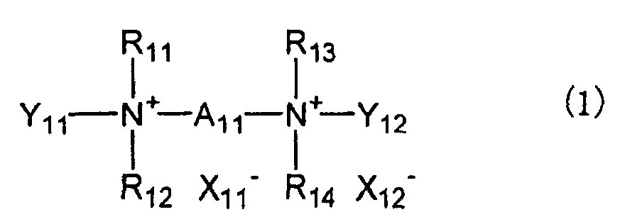
- The humidity sensor device of claim 18 wherein at least 30 mol% of the anions represented by X11 - and X12 - in the copolymer are chloride ions.
- The humidity sensor device of any one of claims 15 to 19 wherein the divalent group represented by A11 in formula (1) is an alkylene, alkenylene or arylene group or a mixture thereof.
- The humidity sensor device of any one of claims 15 to 20 wherein the monovalent groups represented by Y11 and Y12 in formula (1) each are an alkylene acrylate or methacrylate group or alkylene acrylate or methacrylate amide group.
- The humidity sensor device of any one of claims 15 to 21 wherein the monomer of formula (1) is a difunctional monomer obtained by reacting a dialkylaminoethyl acrylate or methacrylate or a dialkylaminoethyl acrylate or methacrylate amide with a dihalogen compound.
- The humidity sensor device of any one of claims 15 to 22 wherein the monomer of formula (1) is obtained by reacting an acrylic unsaturated compound having a dialkylamino group with a dihalogen compound of the divalent group represented by A11 in formula (1).
- A method for preparing a humidity sensor device comprising an insulating substrate, a pair of opposed electrodes disposed on the substrate to define a gap therebetween, and a humidity sensitive thin film lying on the gap, said method comprising the steps of previously treating the insulating substrate with an acrylic monomer having an alkoxysilyl group for joining acrylic functional groups to the insulating substrate, coating a monomer of the following formula (1), then causing the monomer to polymerize to form the humidity sensitive thin film,wherein A11 is a divalent group, each of R11, R12, R13 and R14 which may be the same or different is an alkyl group, each of Y11 and Y12 which may be the same or different is a monovalent group terminated with an unsaturated reactive group, any two or more of R11 to R14, Y11, Y12, A11 and portions thereof adjoining the nitrogen (N) atom may bond together to form a ring with the nitrogen (N) atom, and each of X11 - and X12 - which may be the same or different is an anion.

- A method for preparing a humidity sensor device comprising an insulating substrate, a pair of opposed electrodes disposed on the substrate to define a gap therebetween, and a humidity sensitive thin film lying on the gap, said method comprising the steps of coating a monomer of the following formula (1) and an acrylic monomer having an alkoxysilyl group onto the insulating substrate, causing the monomers to copolymerize into a copolymer, and causing the alkoxysilyl groups to react with functional groups on the surface of the insulating substrate in the presence of water vapor to secure the copolymer to the insulating substrate, for thereby forming the humidity sensitive thin film,wherein A11 is a divalent group, each of R11, R12, R13 and R14 which may be the same or different is an alkyl group, each of Y11 and Y12 which may be the same or different is a monovalent group terminated with an unsaturated reactive group, any two or more of R11 to R14, Y11, Y12, A11 and portions thereof adjoining the nitrogen (N) atom may bond together to form a ring with the nitrogen (N) atom, and each of X11 - and X12 - which may be the same or different is an anion.

- A method for preparing a humidity sensor device comprising an insulating substrate, a pair of opposed electrodes disposed on the substrate to define a gap therebetween, and a humidity sensitive thin film lying on the gap, said method comprising the steps of removing contaminants and/or oxides on the uppermost surface layer of the insulating substrate by physical means, then coating a monomer of the following formula (1) onto the insulating substrate, and causing the monomer to copolymerize on the insulating substrate for thereby forming the humidity sensitive thin film:wherein A11 is a divalent group, each of R11, R12, R13 and R14 which may be the same or different is an alkyl group, each of Y11 and Y12 which may be the same or different is a monovalent group terminated with an unsaturated reactive group, any two or more of R11 to R14, Y11, Y12, A11 and portions thereof adjoining the nitrogen (N) atom may bond together to form a ring with the nitrogen (N) atom, and each of X11 - and X12 - which may be the same or different is an anion.
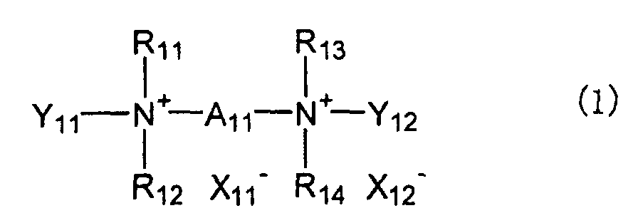
- The method for preparing a humidity sensor device of claim 26 wherein said physical means is plasma surface treatment.
- The method for preparing a humidity sensor device of any one of claims 24 to 27 wherein the polymerization is carried out by irradiation of ultraviolet radiation.
- A method for preparing a humidity sensor device comprising an insulating substrate, a pair of opposed electrodes disposed on the substrate to define a gap therebetween, and a humidity sensitive thin film lying on the gap, said method comprising the steps of removing contaminants and/or oxides on the uppermost surface layer of the insulating substrate by physical means, then coating a monomer having an ethylenically unsaturated reactive group onto the insulating substrate, and causing the monomer to copolymerize on the insulating substrate for thereby forming the humidity sensitive thin film.
- The method for preparing a humidity sensor device of claim 29 wherein said physical means is plasma surface treatment.
- The method for preparing a humidity sensor device of claim 29 or 30 wherein the monomer having an ethylenically unsaturated reactive group contains a quaternary ammonium salt.
- A humidity sensor device comprising an insulating substrate, a pair of opposed electrodes disposed on the substrate to define a gap therebetween, and a humidity sensitive thin film lying on the gap, wherein said the insulating substrate is an insulating substrate from which contaminants and/or oxides on its uppermost surface layer have been removed by physical means, and said humidity sensitive thin film comprises a polymer resulting from a monomer having an ethylenically unsaturated reactive group.
Applications Claiming Priority (11)
| Application Number | Priority Date | Filing Date | Title |
|---|---|---|---|
| JP2001070353 | 2001-03-13 | ||
| JP2001070353 | 2001-03-13 | ||
| JP2001239676 | 2001-08-07 | ||
| JP2001239676 | 2001-08-07 | ||
| JP2002062012 | 2002-03-07 | ||
| JP2002062012A JP2002340833A (en) | 2001-03-13 | 2002-03-07 | Humidity sensor element and manufacturing method thereof |
| JP2002062013A JP3866991B2 (en) | 2001-08-07 | 2002-03-07 | Humidity sensor element and manufacturing method thereof |
| JP2002062013 | 2002-03-07 | ||
| JP2002062011 | 2002-03-07 | ||
| JP2002062011A JP2003262600A (en) | 2002-03-07 | 2002-03-07 | Humidity sensor element and method of manufacturing the same |
| PCT/JP2002/002251 WO2002073178A1 (en) | 2001-03-13 | 2002-03-11 | Humidity sensor element and method for manufacture thereof |
Publications (2)
| Publication Number | Publication Date |
|---|---|
| EP1369683A1 true EP1369683A1 (en) | 2003-12-10 |
| EP1369683A4 EP1369683A4 (en) | 2008-06-18 |
Family
ID=27531827
Family Applications (1)
| Application Number | Title | Priority Date | Filing Date |
|---|---|---|---|
| EP02703961A Ceased EP1369683A4 (en) | 2001-03-13 | 2002-03-11 | Humidity sensor element and method for manufacture thereof |
Country Status (5)
| Country | Link |
|---|---|
| US (1) | US6615659B2 (en) |
| EP (1) | EP1369683A4 (en) |
| CN (1) | CN1301404C (en) |
| TW (1) | TW509791B (en) |
| WO (1) | WO2002073178A1 (en) |
Cited By (1)
| Publication number | Priority date | Publication date | Assignee | Title |
|---|---|---|---|---|
| CN110651180A (en) * | 2017-05-09 | 2020-01-03 | ams国际有限公司 | Super-hydrophobic capacitive humidity sensor and manufacturing method thereof |
Families Citing this family (19)
| Publication number | Priority date | Publication date | Assignee | Title |
|---|---|---|---|---|
| JP3855950B2 (en) * | 2003-03-19 | 2006-12-13 | 株式会社デンソー | Capacitive humidity sensor |
| CN100359323C (en) * | 2003-04-25 | 2008-01-02 | 乐金电子(天津)电器有限公司 | Humidity sensor for microwave oven |
| KR100539392B1 (en) * | 2003-08-12 | 2005-12-27 | (주)해은켐텍 | The Polyelectrolyte composition for humidity sensor, Polyelectrolyte ink and preparation method of Polyelectrolyte membrane for humidity sensor by inkjet printing |
| TW200634304A (en) * | 2005-03-25 | 2006-10-01 | Forward Electronics Co Ltd | Dewing sensor and the method of making the same |
| US20070039385A1 (en) * | 2005-08-18 | 2007-02-22 | Mujie Yang | Resistive thin film humidity sensitive device based on silicone-containing copolymer and its preparation method |
| DE102007011544B3 (en) * | 2007-03-09 | 2008-06-05 | Dräger Medical AG & Co. KG | Breathing moistener controlling method, involves adjusting output of dampness of gas, where measured electrical resistance or capacitance lies as measure of dew of gas, in preset desired value range with maximum and minimum values |
| TW200846636A (en) * | 2007-05-18 | 2008-12-01 | Forward Electronics Co Ltd | Method of manufacturing carbon monoxide sensor and carbon monoxide sensor made thereby |
| US20100307238A1 (en) * | 2009-06-05 | 2010-12-09 | The Governors Of The University Of Alberta | Humidity sensor and method of manufacturing the same |
| EP2315013B1 (en) * | 2009-10-21 | 2014-06-18 | Micronas GmbH | Humidity sensor |
| EP2718706B1 (en) * | 2011-06-08 | 2015-03-11 | 3M Innovative Properties Company | Humidity sensor and sensor element therefor |
| SK500482014A3 (en) * | 2011-12-16 | 2014-10-03 | Elektrotechnický Ústav Sav | Method of plasma processing layer gas sensor sensitive to gas |
| TWI586423B (en) * | 2015-03-12 | 2017-06-11 | 傑智環境科技股份有限公司 | Rotating wheel, fluid treatment apparatus and method for removing treatment canister |
| JP6515683B2 (en) * | 2015-05-29 | 2019-05-22 | 富士通株式会社 | Measuring device and measuring system |
| EP3211408B1 (en) * | 2016-02-29 | 2019-04-10 | Honeywell International Inc. | Relative humidity sensor and method |
| CN106725490B (en) * | 2017-01-23 | 2019-12-27 | 中国科学院合肥物质科学研究院 | Humidity sensor and respiration detection system using same |
| CN110361105B (en) * | 2019-06-20 | 2021-12-31 | 浙江理工大学 | Flexible thin film sensor with linearly related resistance and temperature in wide temperature range |
| US12422391B2 (en) | 2019-08-27 | 2025-09-23 | Chemelex Europe Gmbh | Ruggedized sensor for detecting organic liquids |
| USD953183S1 (en) | 2019-11-01 | 2022-05-31 | Nvent Services Gmbh | Fuel sensor |
| CN112014441A (en) * | 2020-09-04 | 2020-12-01 | 北京化工大学常州先进材料研究院 | Ionic gel humidity sensor, preparation method and application thereof |
Family Cites Families (21)
| Publication number | Priority date | Publication date | Assignee | Title |
|---|---|---|---|---|
| US3689468A (en) * | 1970-12-14 | 1972-09-05 | Rohm & Haas | Unsaturated quaternary monomers and polymers |
| JPS5792012A (en) * | 1980-12-01 | 1982-06-08 | Nitto Boseki Co Ltd | Polymerizing method of quaternary ammonium salt type diallylamine derivative monomer |
| US4322331A (en) * | 1980-12-18 | 1982-03-30 | The Sherwin-Williams Company | Radiation polymerizable compounds and conductive coatings from same |
| EP0076131B1 (en) * | 1981-09-28 | 1986-04-09 | Hitachi, Ltd. | Humidity sensor and method for preparing a humidity sensor |
| JPS60113140A (en) * | 1983-11-25 | 1985-06-19 | Hokuriku Denki Kogyo Kk | Production of moisture sensor element using ionene polymer |
| JPS6154176A (en) | 1984-08-24 | 1986-03-18 | 松下電工株式会社 | Heater disconnection detecting circuit |
| JPS627976A (en) | 1985-07-02 | 1987-01-14 | Honda Motor Co Ltd | Ignition timing control method for internal-combustion engine |
| JPS6283642A (en) * | 1985-10-09 | 1987-04-17 | Sumitomo Cement Co Ltd | Humidity-sensitive element and its preparation |
| JPS6386704A (en) * | 1987-05-21 | 1988-04-18 | Oki Electric Ind Co Ltd | Polymer from compound having phospholipid-like structure |
| FR2644829B2 (en) | 1988-04-15 | 1991-05-17 | Zivanovic Milovoje | ANTI-THEFT DEVICE FOR VEHICLE OR CONTAINER DOORS |
| CN1009863B (en) * | 1988-04-28 | 1990-10-03 | 中国建筑科学研究院空气调节研究所 | Dew sensor |
| JPH02140653A (en) * | 1988-11-21 | 1990-05-30 | Kurabe:Kk | Humidity detecting element |
| CN1034769C (en) * | 1991-11-19 | 1997-04-30 | 电子科技大学 | Non-linear moisture sensor |
| JPH0786493B2 (en) * | 1992-04-24 | 1995-09-20 | 松下電器産業株式会社 | Humidity sensor |
| DE4403409A1 (en) * | 1994-02-04 | 1995-08-10 | Roland Dr Ing Wernecke | Moisture sensor |
| US5546802A (en) * | 1994-03-31 | 1996-08-20 | Tdk Corporation | Humidity sensor and method for making |
| JP2808255B2 (en) | 1994-03-31 | 1998-10-08 | ティーディーケイ株式会社 | Humidity sensor element |
| JP3557245B2 (en) | 1994-05-24 | 2004-08-25 | 松下電器産業株式会社 | Humidity-sensitive element and method of manufacturing the same |
| JP3625348B2 (en) * | 1996-12-10 | 2005-03-02 | Tdk株式会社 | Moisture sensitive element |
| US6241873B1 (en) * | 1997-02-20 | 2001-06-05 | Tdk Corporation | Sold electrolytes, carbon dioxide sensors and method for correcting the output of sensors |
| US6221673B1 (en) * | 1997-11-25 | 2001-04-24 | Microsensor Systems Inc. | Materials, method and apparatus for detection and monitoring of chemical species |
-
2002
- 2002-03-11 EP EP02703961A patent/EP1369683A4/en not_active Ceased
- 2002-03-11 CN CNB028006445A patent/CN1301404C/en not_active Expired - Lifetime
- 2002-03-11 WO PCT/JP2002/002251 patent/WO2002073178A1/en not_active Ceased
- 2002-03-13 US US10/095,435 patent/US6615659B2/en not_active Expired - Lifetime
- 2002-03-13 TW TW091104738A patent/TW509791B/en not_active IP Right Cessation
Cited By (2)
| Publication number | Priority date | Publication date | Assignee | Title |
|---|---|---|---|---|
| CN110651180A (en) * | 2017-05-09 | 2020-01-03 | ams国际有限公司 | Super-hydrophobic capacitive humidity sensor and manufacturing method thereof |
| US11262325B2 (en) | 2017-05-09 | 2022-03-01 | Sciosense B.V. | Sensor semiconductor device |
Also Published As
| Publication number | Publication date |
|---|---|
| US20030056571A1 (en) | 2003-03-27 |
| TW509791B (en) | 2002-11-11 |
| CN1459024A (en) | 2003-11-26 |
| US6615659B2 (en) | 2003-09-09 |
| WO2002073178A1 (en) | 2002-09-19 |
| EP1369683A4 (en) | 2008-06-18 |
| CN1301404C (en) | 2007-02-21 |
Similar Documents
| Publication | Publication Date | Title |
|---|---|---|
| US6615659B2 (en) | Humidity sensor and method for manufacturing the same | |
| US6568265B2 (en) | Humidity sensor and method for making | |
| EP0676636B1 (en) | Humidity sensor and method for making | |
| EP0178071A2 (en) | Moisture sensor and process for producing same | |
| Lee et al. | Humidity‐sensitive properties of new polyelectrolytes based on the copolymers containing phosphonium salt and phosphine function | |
| JP2003262600A (en) | Humidity sensor element and method of manufacturing the same | |
| Lee et al. | Humidity sensitivity of hybrid polyelectrolytes prepared by the sol-gel process | |
| JP2808255B2 (en) | Humidity sensor element | |
| JP3866991B2 (en) | Humidity sensor element and manufacturing method thereof | |
| JP2002340833A (en) | Humidity sensor element and manufacturing method thereof | |
| JP2004301766A (en) | Composition for moisture-sensitive material, moisture-sensitive material and humidity sensor element | |
| JP3967886B2 (en) | Humidity sensor element and manufacturing method thereof | |
| Jeon et al. | Polymeric humidity sensor using polyelectrolyte derived from poly (amide-sulfone) s | |
| JP4513161B2 (en) | Gas sensor manufacturing method and gas sensor | |
| Kim et al. | Water-resistive humidity sensor prepared by printing process using polyelectrolyte ink derived from new monomer | |
| Lee et al. | Humidity-sensitive properties of self-assembled polyelectrolyte system | |
| JPH06160327A (en) | Humidity sensor element and manufacture thereof | |
| JPS6218856B2 (en) | ||
| Lee et al. | Humidity-sensitive properties of polyelectrolytes containing alkoxysilane crosslinkers | |
| JP2001221764A (en) | Humidity sensor element and its manufacturing method | |
| JPS60113140A (en) | Production of moisture sensor element using ionene polymer | |
| JP2005291852A (en) | Humidity sensor element | |
| KR100529537B1 (en) | Humidity Sensor with a High Polymer Membrane | |
| KR100550805B1 (en) | Polymer Film Humidity Sensor | |
| JP2004354083A (en) | Method of manufacturing humidity sensor element |
Legal Events
| Date | Code | Title | Description |
|---|---|---|---|
| PUAI | Public reference made under article 153(3) epc to a published international application that has entered the european phase |
Free format text: ORIGINAL CODE: 0009012 |
|
| 17P | Request for examination filed |
Effective date: 20030705 |
|
| AK | Designated contracting states |
Kind code of ref document: A1 Designated state(s): AT BE CH CY DE DK ES FI FR GB GR IE IT LI LU MC NL PT SE TR |
|
| A4 | Supplementary search report drawn up and despatched |
Effective date: 20080521 |
|
| 17Q | First examination report despatched |
Effective date: 20081103 |
|
| STAA | Information on the status of an ep patent application or granted ep patent |
Free format text: STATUS: THE APPLICATION HAS BEEN REFUSED |
|
| 18R | Application refused |
Effective date: 20100306 |