EP1369630A1 - Cinch strap - Google Patents
Cinch strap Download PDFInfo
- Publication number
- EP1369630A1 EP1369630A1 EP03253469A EP03253469A EP1369630A1 EP 1369630 A1 EP1369630 A1 EP 1369630A1 EP 03253469 A EP03253469 A EP 03253469A EP 03253469 A EP03253469 A EP 03253469A EP 1369630 A1 EP1369630 A1 EP 1369630A1
- Authority
- EP
- European Patent Office
- Prior art keywords
- strap
- aperture
- apertures
- cinch
- segment
- Prior art date
- Legal status (The legal status is an assumption and is not a legal conclusion. Google has not performed a legal analysis and makes no representation as to the accuracy of the status listed.)
- Granted
Links
- 230000007704 transition Effects 0.000 description 2
- 241000191291 Abies alba Species 0.000 description 1
- 239000007787 solid Substances 0.000 description 1
Images
Classifications
-
- B—PERFORMING OPERATIONS; TRANSPORTING
- B65—CONVEYING; PACKING; STORING; HANDLING THIN OR FILAMENTARY MATERIAL
- B65D—CONTAINERS FOR STORAGE OR TRANSPORT OF ARTICLES OR MATERIALS, e.g. BAGS, BARRELS, BOTTLES, BOXES, CANS, CARTONS, CRATES, DRUMS, JARS, TANKS, HOPPERS, FORWARDING CONTAINERS; ACCESSORIES, CLOSURES, OR FITTINGS THEREFOR; PACKAGING ELEMENTS; PACKAGES
- B65D63/00—Flexible elongated elements, e.g. straps, for bundling or supporting articles
- B65D63/10—Non-metallic straps, tapes, or bands; Filamentary elements, e.g. strings, threads or wires; Joints between ends thereof
- B65D63/1018—Joints produced by application of integral securing members, e.g. buckles, wedges, tongue and slot, locking head and teeth or the like
- B65D63/1027—Joints produced by application of integral securing members, e.g. buckles, wedges, tongue and slot, locking head and teeth or the like the integral securing member being formed as a female and male locking member, e.g. locking head and locking teeth, or the like
- B65D63/1063—Joints produced by application of integral securing members, e.g. buckles, wedges, tongue and slot, locking head and teeth or the like the integral securing member being formed as a female and male locking member, e.g. locking head and locking teeth, or the like the female locking member being provided with at least one plastic barb
-
- F—MECHANICAL ENGINEERING; LIGHTING; HEATING; WEAPONS; BLASTING
- F16—ENGINEERING ELEMENTS AND UNITS; GENERAL MEASURES FOR PRODUCING AND MAINTAINING EFFECTIVE FUNCTIONING OF MACHINES OR INSTALLATIONS; THERMAL INSULATION IN GENERAL
- F16L—PIPES; JOINTS OR FITTINGS FOR PIPES; SUPPORTS FOR PIPES, CABLES OR PROTECTIVE TUBING; MEANS FOR THERMAL INSULATION IN GENERAL
- F16L3/00—Supports for pipes, cables or protective tubing, e.g. hangers, holders, clamps, cleats, clips, brackets
- F16L3/22—Supports for pipes, cables or protective tubing, e.g. hangers, holders, clamps, cleats, clips, brackets specially adapted for supporting a number of parallel pipes at intervals
- F16L3/23—Supports for pipes, cables or protective tubing, e.g. hangers, holders, clamps, cleats, clips, brackets specially adapted for supporting a number of parallel pipes at intervals for a bundle of pipes or a plurality of pipes placed side by side in contact with each other
- F16L3/233—Supports for pipes, cables or protective tubing, e.g. hangers, holders, clamps, cleats, clips, brackets specially adapted for supporting a number of parallel pipes at intervals for a bundle of pipes or a plurality of pipes placed side by side in contact with each other by means of a flexible band
- F16L3/2332—Supports for pipes, cables or protective tubing, e.g. hangers, holders, clamps, cleats, clips, brackets specially adapted for supporting a number of parallel pipes at intervals for a bundle of pipes or a plurality of pipes placed side by side in contact with each other by means of a flexible band having a single plastic locking barb
-
- F—MECHANICAL ENGINEERING; LIGHTING; HEATING; WEAPONS; BLASTING
- F16—ENGINEERING ELEMENTS AND UNITS; GENERAL MEASURES FOR PRODUCING AND MAINTAINING EFFECTIVE FUNCTIONING OF MACHINES OR INSTALLATIONS; THERMAL INSULATION IN GENERAL
- F16L—PIPES; JOINTS OR FITTINGS FOR PIPES; SUPPORTS FOR PIPES, CABLES OR PROTECTIVE TUBING; MEANS FOR THERMAL INSULATION IN GENERAL
- F16L3/00—Supports for pipes, cables or protective tubing, e.g. hangers, holders, clamps, cleats, clips, brackets
- F16L3/22—Supports for pipes, cables or protective tubing, e.g. hangers, holders, clamps, cleats, clips, brackets specially adapted for supporting a number of parallel pipes at intervals
- F16L3/23—Supports for pipes, cables or protective tubing, e.g. hangers, holders, clamps, cleats, clips, brackets specially adapted for supporting a number of parallel pipes at intervals for a bundle of pipes or a plurality of pipes placed side by side in contact with each other
- F16L3/233—Supports for pipes, cables or protective tubing, e.g. hangers, holders, clamps, cleats, clips, brackets specially adapted for supporting a number of parallel pipes at intervals for a bundle of pipes or a plurality of pipes placed side by side in contact with each other by means of a flexible band
- F16L3/2336—Supports for pipes, cables or protective tubing, e.g. hangers, holders, clamps, cleats, clips, brackets specially adapted for supporting a number of parallel pipes at intervals for a bundle of pipes or a plurality of pipes placed side by side in contact with each other by means of a flexible band having two or more locking barbs
-
- Y—GENERAL TAGGING OF NEW TECHNOLOGICAL DEVELOPMENTS; GENERAL TAGGING OF CROSS-SECTIONAL TECHNOLOGIES SPANNING OVER SEVERAL SECTIONS OF THE IPC; TECHNICAL SUBJECTS COVERED BY FORMER USPC CROSS-REFERENCE ART COLLECTIONS [XRACs] AND DIGESTS
- Y10—TECHNICAL SUBJECTS COVERED BY FORMER USPC
- Y10T—TECHNICAL SUBJECTS COVERED BY FORMER US CLASSIFICATION
- Y10T24/00—Buckles, buttons, clasps, etc.
- Y10T24/14—Bale and package ties, hose clamps
- Y10T24/1498—Plastic band
Definitions
- Cinch straps, or cable ties are used frequently to secure together items such as bundles of wires or cables, or to secure wires or cables to objects. For example, when two or more wires are run along a common path, to ensure an orderly appearance cinch straps or cable ties are used to bind the wires or cables together. Similar straps can be used to secure one or several wires or cables to a frame, pipe or other object fixed in position relative to the wires. In this way, the wires can be held in an inconspicuous location, and can be protected from dangerous entanglements or other damage.
- Double latch cable ties are known in which a latching mechanism has two latching receptacles, permitting separate bundling of two groups of wires or cables.
- US-A-3654669 teaches a cable tie having a flexible strap secured at one end to a locking frame having two strap accommodating openings therethrough. The strap is of sufficient length to first encircle one group of wires, to be inserted through a first strap accommodating opening in the locking frame, and then around a second group of wires and finally through the second strap accommodating opening in the locking frame.
- two groups of wires are secured on opposite sides of the locking frame by a single, double-latch cable tie.
- U.S. Design Patent 255,782 shows another double latching cable strap in which separate latching structures are provided at right angles to each other, at one end of the strap.
- straps of the type described are useful in securing individual groups or bundles of wires, cables and the like, in some situations it is desirable to provide fixed dimensioned encirclements so that when a plurality of straps are used each is tightened to the same degree, to form encirclements of the same size. Further, in some situations it is desirable and even necessary, to secure the bundled items relatively loosely, to prevent crushing. In the sometimes hectic, rapid pace environments of assembly lines, It is often difficult to ensure that a fixed level of tightening is established,
- the present invention meets the aforementioned and other needs by providing a cinch strap having a strap portion with discrete segments of different physical dimension, and a locking structure having strap receiving openings therethrough suitable for accommodating strap segments of different dimension.
- the present invention provides a cinch strap with a latch block having a plurality of apertures therethrough, each aperture having at least one strap engaging fixture therein.
- a strap is connected to the latch block, and has a plurality of strap segments each including a plurality of adjacent notches for selective engagement with at least one of the strap engaging fixtures.
- the latch block includes at least two apertures of different dimensions, and the strap has at least a first strap portion and a second strap portion of different dimensions. The first strap portion is of a dimension to fit only in a larger of the apertures and the second strap portion is of a dimension to fit in each aperture.
- the present invention provides a cinch strap with a latch block defining first and second apertures therethrough, and an elongated flexible strap extending from the latch block.
- the strap has first and second strap segments.
- the strap segments and the apertures are configured for the second strap segment to pass through both the apertures and for the first strap segment to enter only the first aperture.
- the present invention provides a cinch strap with a monolithic body having an elongated latch block and a strap in substantial alignment therewith.
- the latch block has a first aperture defining a first aperture width nearest the strap and a second aperture defining a second aperture width.
- the strap has a first strap segment adjacent the block, the first strap segment having a first strap width greater than the second aperture width, and the strap having a distal strap portion having a second strap width narrower than the first strap width.
- An advantage of the present invention is providing a cinch strap that can secure separate groups or bundles of objects including wires, cables and the like.
- Another advantage of the present invention is providing a cinch strap establishing at least one fixed dimensioned encirclement for seeming wires cables and the like.
- Still another advantage of the present invention is providing a cinch strap capable of loosely securing bundles of wires, cables and the like.
- Cinch strap 10 designates a cinch strap in accordance with the present invention.
- Cinch strap 10 is shown securing first and second objects 12 and 14, respectively, shown in phantom lines.
- objects 12 and 14 can be groups or bundles of individual items such as wires, cables and the like, or can be other types of objects.
- cinch strap 10 can be used to secure a single wire or cable or a group of wires or cables to a frame, pipe or other object.
- Cinch strap 10 also can be used to secure together two or more groups or bundles of wires and or cables.
- a cinch strap 10 incorporating the principles and features of the present invention will have advantageous use and application in many fields, and the present invention is not limited by the types of items held thereby. It is further noted that although not shown, it should be understood that the cinch strap 10 can be used in combination with a secondary fastener, such as, for example, a christmas tree plastic fastener or a W-prong fastener, both of which are generally known in the automobile industry and other industries, so as to attach the cinch strap 10, and thus the secured objects, to another object.
- a secondary fastener such as, for example, a christmas tree plastic fastener or a W-prong fastener, both of which are generally known in the automobile industry and other industries, so as to attach the cinch strap 10, and thus the secured objects, to another object.
- Cinch strap 10 includes a latch block 16 and a strap 18.
- cinch strap 10 is secured to itself by inserting strap 18 successively through latch block 16, thereby forming first and second encirclements 20 and 22 surrounding objects 12 and 14, respectively.
- Latch block 16 is provided at one end of strap 18 and preferably is formed integrally therewith.
- cinch strap 10 is a monolithic body, advantageously of plastic or the like, including a relatively rigid or firm portion defining latch block 16 and a more flexible, thin portion defining strap 18.
- Latch block 16 is a substantially solid body defining first and second strap receiving apertures 24 and 26 therethrough.
- Apertures 24 and 26 each extend from one side of latch block 16 to another side of latch block 16, thereby defining strap receiving openings by which portions of strap 18 can be passed through latch block 16.
- Apertures 24 and 26 are of different dimensions, Thus, in the exemplary embodiment illustrated, first aperture 24 defines a first aperture width between a first side 28 thereof and a second side 30 thereof.
- Second aperture 26 defines a second aperture width between a first side 32 thereof and a second side 34 thereof The width of first aperture 24 is greater than the width of second aperture 26.
- Each first aperture 24 and second aperture 26 has a strap engaging fixture in the nature of a tooth 36 and a tooth 38, respectively, projecting into the aperture, for engaging strap 18.
- Strap 18 is an elongate flexible body having a first strap segment 40 and second strap segment 42.
- the overall length of strap 18, and the separate lengths of segments 40 and 42 thereof are selected depending upon the size and number of objects 12 and 14 to be held thereby, and the desired sizes for encirclements 20 and 22.
- Latch block 16 and strap 18 are in substantial alignment such that first aperture 24 comprises an inner aperture nearest first strap segment 40, and second aperture 26 comprises an outer aperture more distant from strap 18.
- First strap segment 40 is an inner strap segment, with second strap segment 42 forming an outer segment of a distal portion of strap 18 more distant from latch block 16.
- First strap segment 40 defines a first strap width between a first lateral side 44 thereof and second lateral side 46 thereof.
- Second strap segment 42 defines a second strap width between a first lateral side 48 thereof and a second lateral side 50 thereof.
- the first strep width defined by first strap segment 40 is wider than the second strap width defined by second strap segment 42.
- a shoulder 52 is defined at the transition from first strap segment 40 to second strap segment 42.
- first strap width defined by first strap segment 40 is accommodated by the first aperture width of first aperture 24 but not by the second aperture width of second aperture 26.
- first strap segment 40 can be inserted through first aperture 24 but is too wide to enter or pass through second aperture 26, and shoulder 52 defined between first strap segment 40 and second strap segment 42 will abut a surface of latch block 16 adjacent second aperture 26.
- the second strap width defined by second strip segment 42 readily passes through first aperture 24, and is accommodated by the aperture width of second aperture 26 and is securable therein.
- a first plurality of notches 54 is provided on a surface of first strap segment 40, and a second plurality of notches 56 is provided on a surface of second strap segment 42.
- Notches 54 and 56 thereof are sized and shaped to engage first tooth 36 and second tooth 38, respectively, although each may be of similar size and dimension.
- first tooth 36 and second tooth 38 can be of different dimensions or shapes to be received in different size notches 54 and 56, respectively.
- first strap 18 is extended around first object 12 and is inserted into first aperture 24.
- Second strap segment 42 comprises a distal portion of strap 18 and, being of smaller dimension than first strap segment 40 and first aperture 24 readily passes therethrough. So also, first strap segment 40 can be pulled into first aperture 24, with first tooth 36 therein engaging notches 54 on first segment 40, in known manner, to selectively secure the position of first segment 40 in first aperture 24. Thus, first object 12 is secured within first encirclement 20.
- strip 18 is wrapped around second object 14, and inserted into second aperture 26, thereby forming second encirclement 22 surrounding second object 14.
- Second encirclement 22 can be constricted until second object 14 is securely held therein, or until shoulder 52 abuts against an outer surface of latch block 16 adjacent second aperture 26. Since first strap segment 40 is wider than second aperture 26, strap 18 can be pulled through latch block 16 at second aperture 26 only until first strap segment 40, and specifically shoulder 52, encounters second aperture 26.
- latch block 16 having two apertures 24 and 26 has been shown and described herein, latch block 16 could also have three or more apertures accommodating two or more strap segments 40, 42.
- one or several apertures can be sized to accommodate one or the other portions of strap 16 or, alternatively, three or more apertures can be provided each of different width, each accommodating a different width strap portion.
- strap segments can be provided of progressively narrower widths from latch block 16 to a distal tip of strap 18, to be received in successively narrower openings defined in a plurality of apertures. Shoulders such as shoulder 52 can be provided at the transitions between adjacent strap segments so that a plurality of fixed minimum diameter encirclements are formed.
- first and second segments 40 and 42 are also possible.
- segments 40 and 42 also could be provided of the same width, but of different thickness.
- Apertures 24 and 26 would then be provided of appropriate shape such that a thinner strap segment will pass through each aperture, while the thick strap segment will pass through only one aperture.
- First aperture 24 and first strap segment 40 can be of a first shape, and second aperture 26 and strap segment 42 of a different, smaller shape such that second segment 42 will pass through first aperture 24, but first segment 40 is too large in at least one dimension to pass through second aperture 26.
- First aperture 24 and first strap segment 40 can be substantially rectangular and second aperture 26 and second strap segment 42 triangular.
Landscapes
- Engineering & Computer Science (AREA)
- General Engineering & Computer Science (AREA)
- Mechanical Engineering (AREA)
- Package Frames And Binding Bands (AREA)
- Clamps And Clips (AREA)
- Buckles (AREA)
Abstract
Description
- Cinch straps, or cable ties, are used frequently to secure together items such as bundles of wires or cables, or to secure wires or cables to objects. For example, when two or more wires are run along a common path, to ensure an orderly appearance cinch straps or cable ties are used to bind the wires or cables together. Similar straps can be used to secure one or several wires or cables to a frame, pipe or other object fixed in position relative to the wires. In this way, the wires can be held in an inconspicuous location, and can be protected from dangerous entanglements or other damage.
- Double latch cable ties are known in which a latching mechanism has two latching receptacles, permitting separate bundling of two groups of wires or cables. For example, US-A-3654669 teaches a cable tie having a flexible strap secured at one end to a locking frame having two strap accommodating openings therethrough. The strap is of sufficient length to first encircle one group of wires, to be inserted through a first strap accommodating opening in the locking frame, and then around a second group of wires and finally through the second strap accommodating opening in the locking frame. Thus, two groups of wires are secured on opposite sides of the locking frame by a single, double-latch cable tie.
- U.S. Design Patent 255,782 shows another double latching cable strap in which separate latching structures are provided at right angles to each other, at one end of the strap.
- While straps of the type described are useful in securing individual groups or bundles of wires, cables and the like, in some situations it is desirable to provide fixed dimensioned encirclements so that when a plurality of straps are used each is tightened to the same degree, to form encirclements of the same size. Further, in some situations it is desirable and even necessary, to secure the bundled items relatively loosely, to prevent crushing. In the sometimes hectic, rapid pace environments of assembly lines, It is often difficult to ensure that a fixed level of tightening is established,
- What is needed in the art is a cinch strap providing multiple encirclements, at least some with fixed minimum diameters.
- The present invention meets the aforementioned and other needs by providing a cinch strap having a strap portion with discrete segments of different physical dimension, and a locking structure having strap receiving openings therethrough suitable for accommodating strap segments of different dimension.
- In one form thereof, the present invention provides a cinch strap with a latch block having a plurality of apertures therethrough, each aperture having at least one strap engaging fixture therein. A strap is connected to the latch block, and has a plurality of strap segments each including a plurality of adjacent notches for selective engagement with at least one of the strap engaging fixtures. The latch block includes at least two apertures of different dimensions, and the strap has at least a first strap portion and a second strap portion of different dimensions. The first strap portion is of a dimension to fit only in a larger of the apertures and the second strap portion is of a dimension to fit in each aperture.
- In another form thereof, the present invention provides a cinch strap with a latch block defining first and second apertures therethrough, and an elongated flexible strap extending from the latch block. The strap has first and second strap segments. The strap segments and the apertures are configured for the second strap segment to pass through both the apertures and for the first strap segment to enter only the first aperture.
- In still another form thereof, the present invention provides a cinch strap with a monolithic body having an elongated latch block and a strap in substantial alignment therewith. The latch block has a first aperture defining a first aperture width nearest the strap and a second aperture defining a second aperture width. The strap has a first strap segment adjacent the block, the first strap segment having a first strap width greater than the second aperture width, and the strap having a distal strap portion having a second strap width narrower than the first strap width.
- An advantage of the present invention is providing a cinch strap that can secure separate groups or bundles of objects including wires, cables and the like.
- Another advantage of the present invention is providing a cinch strap establishing at least one fixed dimensioned encirclement for seeming wires cables and the like.
- Still another advantage of the present invention is providing a cinch strap capable of loosely securing bundles of wires, cables and the like.
- A particular embodiment in accordance with this invention will now be described with reference to the accompanying drawings, in which:-
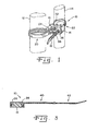
- Fig. 1 is a perspective view illustrating the manner of use of a cinch strap in accordance with the present invention;
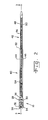
- Fig. 2 is a plan view of the cinch strap shown in Fig. 1; and,
- Fig. 3 is a cross-sectional view of the cinch strap shown in Fig. 2, taken along line 3-3 of Fig. 2.
-
- Referring now more specifically to the drawings, and to Fig. 1 in particular,
numeral 10 designates a cinch strap in accordance with the present invention.Cinch strap 10 is shown securing first andsecond objects objects cinch strap 10 can be used to secure a single wire or cable or a group of wires or cables to a frame, pipe or other object.Cinch strap 10 also can be used to secure together two or more groups or bundles of wires and or cables. It is expected that acinch strap 10 incorporating the principles and features of the present invention will have advantageous use and application in many fields, and the present invention is not limited by the types of items held thereby. It is further noted that although not shown, it should be understood that thecinch strap 10 can be used in combination with a secondary fastener, such as, for example, a christmas tree plastic fastener or a W-prong fastener, both of which are generally known in the automobile industry and other industries, so as to attach thecinch strap 10, and thus the secured objects, to another object. -
Cinch strap 10 includes alatch block 16 and astrap 18. In the exemplary embodiment shown in Fig. 1,cinch strap 10 is secured to itself by insertingstrap 18 successively throughlatch block 16, thereby forming first andsecond encirclements objects -
Latch block 16 is provided at one end ofstrap 18 and preferably is formed integrally therewith. Thus,cinch strap 10 is a monolithic body, advantageously of plastic or the like, including a relatively rigid or firm portion defininglatch block 16 and a more flexible, thinportion defining strap 18. -
Latch block 16 is a substantially solid body defining first and secondstrap receiving apertures Apertures latch block 16 to another side oflatch block 16, thereby defining strap receiving openings by which portions ofstrap 18 can be passed throughlatch block 16.Apertures first aperture 24 defines a first aperture width between afirst side 28 thereof and asecond side 30 thereof.Second aperture 26 defines a second aperture width between afirst side 32 thereof and asecond side 34 thereof The width offirst aperture 24 is greater than the width ofsecond aperture 26. Eachfirst aperture 24 andsecond aperture 26 has a strap engaging fixture in the nature of atooth 36 and atooth 38, respectively, projecting into the aperture, for engagingstrap 18. -
Strap 18 is an elongate flexible body having afirst strap segment 40 andsecond strap segment 42. The overall length ofstrap 18, and the separate lengths ofsegments objects encirclements - Latch
block 16 andstrap 18 are in substantial alignment such thatfirst aperture 24 comprises an inner aperture nearestfirst strap segment 40, andsecond aperture 26 comprises an outer aperture more distant fromstrap 18.First strap segment 40 is an inner strap segment, withsecond strap segment 42 forming an outer segment of a distal portion ofstrap 18 more distant fromlatch block 16. -
First strap segment 40 defines a first strap width between a firstlateral side 44 thereof and secondlateral side 46 thereof.Second strap segment 42 defines a second strap width between a firstlateral side 48 thereof and a secondlateral side 50 thereof. The first strep width defined byfirst strap segment 40 is wider than the second strap width defined bysecond strap segment 42. Ashoulder 52 is defined at the transition fromfirst strap segment 40 tosecond strap segment 42. - The first strap width defined by
first strap segment 40 is accommodated by the first aperture width offirst aperture 24 but not by the second aperture width ofsecond aperture 26. Thus,first strap segment 40 can be inserted throughfirst aperture 24 but is too wide to enter or pass throughsecond aperture 26, andshoulder 52 defined betweenfirst strap segment 40 andsecond strap segment 42 will abut a surface oflatch block 16 adjacentsecond aperture 26. The second strap width defined bysecond strip segment 42 readily passes throughfirst aperture 24, and is accommodated by the aperture width ofsecond aperture 26 and is securable therein. - A first plurality of
notches 54 is provided on a surface offirst strap segment 40, and a second plurality ofnotches 56 is provided on a surface ofsecond strap segment 42.Notches first tooth 36 andsecond tooth 38, respectively, although each may be of similar size and dimension. Alternatively,first tooth 36 andsecond tooth 38 can be of different dimensions or shapes to be received indifferent size notches - In the use of
cinch strap 10,strap 18 is extended aroundfirst object 12 and is inserted intofirst aperture 24.Second strap segment 42 comprises a distal portion ofstrap 18 and, being of smaller dimension thanfirst strap segment 40 andfirst aperture 24 readily passes therethrough. So also,first strap segment 40 can be pulled intofirst aperture 24, withfirst tooth 36 therein engagingnotches 54 onfirst segment 40, in known manner, to selectively secure the position offirst segment 40 infirst aperture 24. Thus,first object 12 is secured withinfirst encirclement 20. - Thereafter,
strip 18 is wrapped aroundsecond object 14, and inserted intosecond aperture 26, thereby formingsecond encirclement 22 surroundingsecond object 14.Second encirclement 22 can be constricted untilsecond object 14 is securely held therein, or untilshoulder 52 abuts against an outer surface oflatch block 16 adjacentsecond aperture 26. Sincefirst strap segment 40 is wider thansecond aperture 26,strap 18 can be pulled throughlatch block 16 atsecond aperture 26 only untilfirst strap segment 40, and specifically shoulder 52, encounterssecond aperture 26. - Those skilled in the art should readily understand that while
latch block 16 having twoapertures latch block 16 could also have three or more apertures accommodating two ormore strap segments strap 16 or, alternatively, three or more apertures can be provided each of different width, each accommodating a different width strap portion. Thus, strap segments can be provided of progressively narrower widths fromlatch block 16 to a distal tip ofstrap 18, to be received in successively narrower openings defined in a plurality of apertures. Shoulders such asshoulder 52 can be provided at the transitions between adjacent strap segments so that a plurality of fixed minimum diameter encirclements are formed. - Other variations in the present invention are also possible. For example, while
strap 18 has been shown and described herein as having first andsecond segments segments First aperture 24 andfirst strap segment 40 can be of a first shape, andsecond aperture 26 andstrap segment 42 of a different, smaller shape such thatsecond segment 42 will pass throughfirst aperture 24, butfirst segment 40 is too large in at least one dimension to pass throughsecond aperture 26.First aperture 24 andfirst strap segment 40 can be substantially rectangular andsecond aperture 26 andsecond strap segment 42 triangular. Other combinations of appropriate geometric shapes, including, but not limited to rectangular, triangular and round shapes, in appropriate sizes also can be used. The present invention requires only that one portion ofstrap 18 is shaped in conjunction with the apertures to fit in each aperture, while another portion of strap 13 is shaped to fit in less than all of the apertures.
Claims (10)
- A cinch strap (10) comprising;characterised in that said latch block (16) includes at least two said apertures (24,26) of different dimensions; and in that said strap has at least a first strap portion (40) and a second strap portion (42) of different dimensions, said first strap portion (40) being of a dimension to fit only in a larger of said apertures (24,26) and said second strap portion (42) being of a dimension to fit in both of said apertures (24, 26).a latch block (16) having a plurality of apertures (24,26) therethrough each said aperture (24,26) having at least one strap engaging fixture (36, 38) therein; and,a strap (18) connected to said latch block (16), said strap (18) having a plurality of strap segments (40,42) each including a plurality of adjacent notches (54) for selectively engaging at least one of said strap engaging fixtures (36,38),
- A cinch strap according to claim 1, said plurality of apertures (24,26) being two apertures, and said plurality of strap portions (40,42) being two strap segments.
- A cinch strap according claim 1 or claim 2, wherein latch block (16) has an inner said aperture (24) adjacent said strap (16) and an outer said aperture (26).
- A cinch strap according to claim 3, said strap (16) having an inner strap segment (40) adjacent said latch block (16) and an outer strap segment (42), said inner strap segment (40) having a width greater than the width of said outer strap segment (42).
- A cinch strap according to any one of the preceding claims, wherein said apertures (24,26) are substantially rectangular.
- A cinch strap according to any one of the preceding claims, wherein said strap (18) and said latch block (18) comprises a monolithic structure.
- A cinch strap comprising;said strap segments and said apertures being configured for said second strap segment to pass through both said apertures and for said first strap segment to enter only said first aperture.a latch block defining first and second apertures therethrough;an elongated flexible strap extending from said latch block, said strap having first and second strap segments; and
- A cinch strap comprising;a monolithic structure having an elongated latch block and a strap in substantial alignment therewith;said latch block having an aperture defining an aperture width; andsaid strap having a first strap segment adjacent said block, said first strap segment having a first strip width greater than said aperture width, and said strap having a distal strap portion having a second strap width narrower than said first strap width.
- The cinch strap of claim 8, wherein the latch block includes another aperture defining another aperture width which is greater than said aperture width.
- The cinch strap of claim 9, said strap having a plurality of notches along a surface thereof, and each said aperture having a tooth therein for engaging at least some of said notches.
Applications Claiming Priority (4)
| Application Number | Priority Date | Filing Date | Title |
|---|---|---|---|
| US38682502P | 2002-06-07 | 2002-06-07 | |
| US386825P | 2002-06-07 | ||
| US10/386,855 US7131168B2 (en) | 2002-06-07 | 2003-03-12 | Cinch strap |
| US386855 | 2003-03-12 |
Publications (2)
| Publication Number | Publication Date |
|---|---|
| EP1369630A1 true EP1369630A1 (en) | 2003-12-10 |
| EP1369630B1 EP1369630B1 (en) | 2008-12-10 |
Family
ID=29553646
Family Applications (1)
| Application Number | Title | Priority Date | Filing Date |
|---|---|---|---|
| EP03253469A Expired - Lifetime EP1369630B1 (en) | 2002-06-07 | 2003-06-03 | Cinch strap |
Country Status (4)
| Country | Link |
|---|---|
| US (1) | US7131168B2 (en) |
| EP (1) | EP1369630B1 (en) |
| CA (1) | CA2431476C (en) |
| DE (1) | DE60325139D1 (en) |
Cited By (6)
| Publication number | Priority date | Publication date | Assignee | Title |
|---|---|---|---|---|
| GB2398828A (en) * | 2003-01-10 | 2004-09-01 | Phil Head | A cable clamp device |
| CN103303574A (en) * | 2013-07-08 | 2013-09-18 | 苏州苏越电气有限公司 | Tie |
| CN103303575A (en) * | 2013-07-08 | 2013-09-18 | 苏州苏越电气有限公司 | Improved cable assembly |
| CN103318532A (en) * | 2013-07-08 | 2013-09-25 | 苏州苏越电气有限公司 | Improved tie |
| CN103342193A (en) * | 2013-07-08 | 2013-10-09 | 苏州币龙装饰工程有限公司 | Wired electric appliance with fishbone tying belt |
| US20230261457A1 (en) * | 2022-02-17 | 2023-08-17 | Joshua John Muscat | Device for cable management |
Families Citing this family (39)
| Publication number | Priority date | Publication date | Assignee | Title |
|---|---|---|---|---|
| US20050076478A1 (en) * | 2003-07-04 | 2005-04-14 | Sumitomo Wiring Systems, Ltd. | Branch wire tie band, binding structure, and method of binding a wiring harness |
| US20050178580A1 (en) * | 2004-02-13 | 2005-08-18 | Holland Joseph W. | Conductor support |
| US20070023586A1 (en) * | 2005-07-28 | 2007-02-01 | Hellermann Tyton Corporation | Harness clamp tie |
| WO2008098124A1 (en) | 2007-02-07 | 2008-08-14 | Boston Scientific Scimed, Inc. | Attachment clamp |
| US7774905B2 (en) * | 2007-02-14 | 2010-08-17 | Hellermanntyton Corporation | Element of a cable tie strap |
| US7437804B1 (en) | 2007-05-25 | 2008-10-21 | Hellermanntyton Corporation | Clamp tie |
| USD570673S1 (en) * | 2007-05-25 | 2008-06-10 | Hellermanntyton Corporation | Clamp tie |
| US20110147541A1 (en) * | 2009-12-23 | 2011-06-23 | Caterpillar Inc. | Cable strap locating device for a wire harness and a wire harness assembly using the same |
| US8595904B2 (en) * | 2010-01-11 | 2013-12-03 | Jersey Tactical Corp. | Disposable double lock restraint system |
| USD634187S1 (en) * | 2010-10-14 | 2011-03-15 | Kozel Cyril J | Hangable cable tie |
| US8559782B2 (en) * | 2010-11-11 | 2013-10-15 | The Boeing Company | Conductor assembly, conductor spacer and associated method of separating conductors |
| USD687632S1 (en) | 2011-02-11 | 2013-08-13 | Drenaline Products, Llc | Combined golf bag and banner |
| DE202011050271U1 (en) * | 2011-05-27 | 2012-08-28 | Cofresco Frischhalteprodukte Gmbh & Co. Kg | closure element |
| US9021681B2 (en) * | 2012-09-27 | 2015-05-05 | Thomas Dale Owen | Mountable cable tie with fine adjustment and method of use thereof |
| US9073677B2 (en) | 2013-02-22 | 2015-07-07 | Panduit Corp. | Dual head metal locking tie |
| US9725220B2 (en) | 2013-08-05 | 2017-08-08 | Rolf Dietrich | Flexible connector |
| US8739387B1 (en) | 2013-11-05 | 2014-06-03 | Dov Frishberg | Reusable cable tie |
| USD739714S1 (en) * | 2014-02-20 | 2015-09-29 | Hellermanntyton Corporation | Aerial support tie |
| US20160244228A1 (en) * | 2014-02-21 | 2016-08-25 | Raul Eduardo Montejo | Double Sided Closure Fastener |
| NZ736091A (en) * | 2014-07-14 | 2018-12-21 | Illinois Tool Works | Improvements relating to lifting of building units |
| US9328539B1 (en) | 2014-07-28 | 2016-05-03 | Anthony E. Lonardo | Manacle restraining device |
| US9958089B2 (en) * | 2014-09-29 | 2018-05-01 | Hellermanntyton Corporation | Lashing support spacer tie |
| US9637291B2 (en) | 2015-03-26 | 2017-05-02 | Raul Eduardo Montejo | Multi-positional closure fastener |
| KR101802510B1 (en) * | 2015-05-28 | 2017-11-28 | 계명대학교 산학협력단 | Cable tie |
| US10053268B1 (en) * | 2015-09-09 | 2018-08-21 | The United States Of America As Represented By The Secretary Of The Army | Cable tie with multi-slot head for attachments |
| US20170088322A1 (en) * | 2015-09-25 | 2017-03-30 | David Reinke | Cable tie |
| USD785875S1 (en) * | 2016-08-21 | 2017-05-02 | Tisha G. Martinsek | Poultry leg band with charm attached |
| US10513380B2 (en) | 2017-03-29 | 2019-12-24 | James Watson | Hybrid fastener strap having positioning detents |
| USD844416S1 (en) * | 2017-06-08 | 2019-04-02 | Hellermanntyton Corporation | Tie tail cut-off shield |
| USD835495S1 (en) * | 2017-07-20 | 2018-12-11 | Tenacious Holdings, Inc. | Cable tie anchor point |
| US10786641B1 (en) * | 2017-08-29 | 2020-09-29 | Georgi Patraka | Medical tube securing device |
| US10994906B2 (en) * | 2017-10-23 | 2021-05-04 | Erik Vaclav Chmelar | Easy-to-remove cable tie |
| CN111512082A (en) * | 2017-12-01 | 2020-08-07 | 豪倍公司 | Cable binding band |
| US11180299B1 (en) | 2019-10-09 | 2021-11-23 | Raul E. Montejo | Rotatable multipositional fasteners |
| GB2591823A (en) * | 2020-02-10 | 2021-08-11 | Francis Slater Nigel | An adaptor for use with an elongate strip |
| US12326210B2 (en) | 2022-03-24 | 2025-06-10 | Hellermanntyton Corporation | Quick attach clamp |
| US12338848B2 (en) | 2022-06-30 | 2025-06-24 | Hellermanntyton Corporation | Anti-wobble fir tree mount |
| US20240360922A1 (en) | 2023-04-28 | 2024-10-31 | Hellermanntyton Corporation | Cable Tie Cradle Mount Fixings |
| US20250035237A1 (en) * | 2023-07-24 | 2025-01-30 | Dale Baker | Cable tie device |
Citations (4)
| Publication number | Priority date | Publication date | Assignee | Title |
|---|---|---|---|---|
| US3654669A (en) * | 1970-03-31 | 1972-04-11 | Panduit Corp | Double-latch cable tie |
| GB2243401A (en) * | 1987-09-25 | 1991-10-30 | Bowthorpe Hellermann Ltd | Plastics tie |
| DE19622087A1 (en) * | 1995-05-31 | 1996-12-05 | Robert Vaverka | Fastener with clip for clasping around loop-shaped objects |
| GB2352477A (en) * | 1999-07-15 | 2001-01-31 | Inter Trading Sports Associate | Securing tie |
Family Cites Families (25)
| Publication number | Priority date | Publication date | Assignee | Title |
|---|---|---|---|---|
| US3106028A (en) * | 1960-05-26 | 1963-10-08 | John G Baumgartner | Identification band |
| US3257694A (en) * | 1963-03-21 | 1966-06-28 | Walter J Litwin | Self-locking tamper proof strap |
| US3149808A (en) | 1963-09-25 | 1964-09-22 | Weckesser Co | Wedge-lock band clamp |
| GB1079888A (en) | 1964-12-01 | 1967-08-16 | Ft Products Ltd | Improvements in and relating to fasteners |
| US3556575A (en) * | 1968-11-15 | 1971-01-19 | Thomas & Betts Corp | Tamperproof seal |
| US4688302A (en) | 1969-04-07 | 1987-08-25 | Panduit Corp. | One-piece cable tie |
| US3597803A (en) | 1969-07-02 | 1971-08-10 | Eaton Yale & Towne | Fastening device |
| US3908233A (en) | 1969-07-03 | 1975-09-30 | Panduit Corp | Releasable one-piece cable tie |
| US3731347A (en) * | 1971-03-16 | 1973-05-08 | Panduit Corp | Cable tie |
| US3747164A (en) | 1972-11-01 | 1973-07-24 | Thomas & Betts Corp | Releasable self-locking bundling strap |
| GB1544163A (en) * | 1976-09-27 | 1979-04-11 | Promex Plastics Ltd | Identification band |
| USD255782S (en) | 1977-05-31 | 1980-07-08 | Gte Products Corporation | Tie strap |
| US4991265A (en) | 1989-11-20 | 1991-02-12 | Best Shot | Cord tie device |
| USD326406S (en) | 1990-01-11 | 1992-05-26 | Custom Molders, Inc. | Strap fastener |
| FR2699611B1 (en) | 1992-12-23 | 1995-05-24 | Trw Carr France Sa | Synthetic cable band. |
| US5395343A (en) * | 1993-10-21 | 1995-03-07 | Iscovich; Angel | Anchoring device for medical tubing |
| US5524945A (en) * | 1994-04-06 | 1996-06-11 | E. J. Brooks Company | Thermoplastic security seal |
| US5924171A (en) | 1995-01-27 | 1999-07-20 | Gb Electrical, Inc. | Cable tie having enhanced locking action |
| US6003208A (en) | 1995-12-13 | 1999-12-21 | Tyton Hellerman Corporation | Parallel entry tie |
| CA2168588C (en) | 1996-02-01 | 1998-01-06 | Gerald Villeneuve | Reversible permanent or re-usable fastener |
| NL1004356C1 (en) * | 1996-10-24 | 1998-04-27 | Guno Maximiliaan Valies | Tying strip for use as cleat enclosing bundle of cables |
| US6102347A (en) | 1997-09-03 | 2000-08-15 | Avery Dennison Corporation | Cable tie |
| US6185792B1 (en) | 1997-11-21 | 2001-02-13 | Thomas & Betts International, Inc. | Bi-directional self-locking cable tie |
| US6105210A (en) | 1998-07-08 | 2000-08-22 | Avery Dennison Corporation | Merchandise pairing tie |
| US6151761A (en) * | 1998-09-28 | 2000-11-28 | Thompson; Greg | Flexible restraining device |
-
2003
- 2003-03-12 US US10/386,855 patent/US7131168B2/en not_active Expired - Fee Related
- 2003-06-03 DE DE60325139T patent/DE60325139D1/en not_active Expired - Lifetime
- 2003-06-03 EP EP03253469A patent/EP1369630B1/en not_active Expired - Lifetime
- 2003-06-09 CA CA002431476A patent/CA2431476C/en not_active Expired - Fee Related
Patent Citations (4)
| Publication number | Priority date | Publication date | Assignee | Title |
|---|---|---|---|---|
| US3654669A (en) * | 1970-03-31 | 1972-04-11 | Panduit Corp | Double-latch cable tie |
| GB2243401A (en) * | 1987-09-25 | 1991-10-30 | Bowthorpe Hellermann Ltd | Plastics tie |
| DE19622087A1 (en) * | 1995-05-31 | 1996-12-05 | Robert Vaverka | Fastener with clip for clasping around loop-shaped objects |
| GB2352477A (en) * | 1999-07-15 | 2001-01-31 | Inter Trading Sports Associate | Securing tie |
Cited By (8)
| Publication number | Priority date | Publication date | Assignee | Title |
|---|---|---|---|---|
| GB2398828A (en) * | 2003-01-10 | 2004-09-01 | Phil Head | A cable clamp device |
| CN103303574A (en) * | 2013-07-08 | 2013-09-18 | 苏州苏越电气有限公司 | Tie |
| CN103303575A (en) * | 2013-07-08 | 2013-09-18 | 苏州苏越电气有限公司 | Improved cable assembly |
| CN103318532A (en) * | 2013-07-08 | 2013-09-25 | 苏州苏越电气有限公司 | Improved tie |
| CN103342193A (en) * | 2013-07-08 | 2013-10-09 | 苏州币龙装饰工程有限公司 | Wired electric appliance with fishbone tying belt |
| CN103342193B (en) * | 2013-07-08 | 2016-01-06 | 李建勋 | There is wired electrical equipment of Fishbone tie |
| US20230261457A1 (en) * | 2022-02-17 | 2023-08-17 | Joshua John Muscat | Device for cable management |
| US12040603B2 (en) * | 2022-02-17 | 2024-07-16 | Joshua John Muscat | Device for cable management |
Also Published As
| Publication number | Publication date |
|---|---|
| DE60325139D1 (en) | 2009-01-22 |
| CA2431476C (en) | 2008-02-12 |
| US7131168B2 (en) | 2006-11-07 |
| US20030226243A1 (en) | 2003-12-11 |
| CA2431476A1 (en) | 2003-12-07 |
| EP1369630B1 (en) | 2008-12-10 |
Similar Documents
| Publication | Publication Date | Title |
|---|---|---|
| EP1369630B1 (en) | Cinch strap | |
| US5135188A (en) | Attachable bundling strap | |
| US6751382B2 (en) | System for organizing wires and cables | |
| US6640393B2 (en) | Releasable tie | |
| US6516498B2 (en) | Clamps | |
| US6189187B1 (en) | Clip for holding a pair of elongated member portions | |
| US9637291B2 (en) | Multi-positional closure fastener | |
| US5752682A (en) | Anchor for receiving cable bundling straps | |
| US5653409A (en) | Standoff | |
| US5402971A (en) | Cable tie having loop attachment | |
| US11002383B2 (en) | Combination securing clips | |
| AU695333B2 (en) | Cable tie having an improved strap locking device | |
| US6253421B1 (en) | Plastic holding strap with elastic locking element for locking the holding strap by engagement with bundled articles | |
| CN1468785A (en) | Straps for harness branches | |
| US9121528B2 (en) | High strength blind installation hose and cable clamp retainer | |
| US20060162130A1 (en) | Cable tie | |
| US12040603B2 (en) | Device for cable management | |
| EP3712478B1 (en) | Cable tie with with an adjustable head | |
| US4978091A (en) | Bundling strap | |
| US20160244228A1 (en) | Double Sided Closure Fastener | |
| US9624016B1 (en) | Multi-surface cable tying device | |
| US4896852A (en) | Bundling band | |
| US5964013A (en) | Cable tie with cable protection features | |
| US20030070263A1 (en) | Cable tie style tail with improved grip | |
| US20210123502A1 (en) | Cord tightening and retaining device |
Legal Events
| Date | Code | Title | Description |
|---|---|---|---|
| PUAI | Public reference made under article 153(3) epc to a published international application that has entered the european phase |
Free format text: ORIGINAL CODE: 0009012 |
|
| AK | Designated contracting states |
Kind code of ref document: A1 Designated state(s): AT BE BG CH CY CZ DE DK EE ES FI FR GB GR HU IE IT LI LU MC NL PT RO SE SI SK TR |
|
| AX | Request for extension of the european patent |
Extension state: AL LT LV MK |
|
| 17P | Request for examination filed |
Effective date: 20040526 |
|
| AKX | Designation fees paid |
Designated state(s): DE FR IT |
|
| 17Q | First examination report despatched |
Effective date: 20050513 |
|
| 17Q | First examination report despatched |
Effective date: 20050513 |
|
| GRAP | Despatch of communication of intention to grant a patent |
Free format text: ORIGINAL CODE: EPIDOSNIGR1 |
|
| GRAS | Grant fee paid |
Free format text: ORIGINAL CODE: EPIDOSNIGR3 |
|
| GRAA | (expected) grant |
Free format text: ORIGINAL CODE: 0009210 |
|
| AK | Designated contracting states |
Kind code of ref document: B1 Designated state(s): DE FR IT |
|
| REF | Corresponds to: |
Ref document number: 60325139 Country of ref document: DE Date of ref document: 20090122 Kind code of ref document: P |
|
| PLBE | No opposition filed within time limit |
Free format text: ORIGINAL CODE: 0009261 |
|
| STAA | Information on the status of an ep patent application or granted ep patent |
Free format text: STATUS: NO OPPOSITION FILED WITHIN TIME LIMIT |
|
| 26N | No opposition filed |
Effective date: 20090911 |
|
| PGFP | Annual fee paid to national office [announced via postgrant information from national office to epo] |
Ref country code: DE Payment date: 20120627 Year of fee payment: 10 |
|
| PGFP | Annual fee paid to national office [announced via postgrant information from national office to epo] |
Ref country code: FR Payment date: 20120705 Year of fee payment: 10 |
|
| PGFP | Annual fee paid to national office [announced via postgrant information from national office to epo] |
Ref country code: IT Payment date: 20130624 Year of fee payment: 11 |
|
| REG | Reference to a national code |
Ref country code: FR Ref legal event code: ST Effective date: 20140228 |
|
| REG | Reference to a national code |
Ref country code: DE Ref legal event code: R119 Ref document number: 60325139 Country of ref document: DE Effective date: 20140101 |
|
| PG25 | Lapsed in a contracting state [announced via postgrant information from national office to epo] |
Ref country code: DE Free format text: LAPSE BECAUSE OF NON-PAYMENT OF DUE FEES Effective date: 20140101 |
|
| PG25 | Lapsed in a contracting state [announced via postgrant information from national office to epo] |
Ref country code: FR Free format text: LAPSE BECAUSE OF NON-PAYMENT OF DUE FEES Effective date: 20130701 |
|
| PG25 | Lapsed in a contracting state [announced via postgrant information from national office to epo] |
Ref country code: IT Free format text: LAPSE BECAUSE OF NON-PAYMENT OF DUE FEES Effective date: 20140603 |