EP1369612A2 - Toothed electromagnetic clutch-brake - Google Patents
Toothed electromagnetic clutch-brake Download PDFInfo
- Publication number
- EP1369612A2 EP1369612A2 EP03253556A EP03253556A EP1369612A2 EP 1369612 A2 EP1369612 A2 EP 1369612A2 EP 03253556 A EP03253556 A EP 03253556A EP 03253556 A EP03253556 A EP 03253556A EP 1369612 A2 EP1369612 A2 EP 1369612A2
- Authority
- EP
- European Patent Office
- Prior art keywords
- armature
- ring
- rotor
- teeth
- millimeters
- Prior art date
- Legal status (The legal status is an assumption and is not a legal conclusion. Google has not performed a legal analysis and makes no representation as to the accuracy of the status listed.)
- Withdrawn
Links
Images
Classifications
-
- F—MECHANICAL ENGINEERING; LIGHTING; HEATING; WEAPONS; BLASTING
- F16—ENGINEERING ELEMENTS AND UNITS; GENERAL MEASURES FOR PRODUCING AND MAINTAINING EFFECTIVE FUNCTIONING OF MACHINES OR INSTALLATIONS; THERMAL INSULATION IN GENERAL
- F16D—COUPLINGS FOR TRANSMITTING ROTATION; CLUTCHES; BRAKES
- F16D27/00—Magnetically- or electrically- actuated clutches; Control or electric circuits therefor
- F16D27/10—Magnetically- or electrically- actuated clutches; Control or electric circuits therefor with an electromagnet not rotating with a clutching member, i.e. without collecting rings
- F16D27/118—Magnetically- or electrically- actuated clutches; Control or electric circuits therefor with an electromagnet not rotating with a clutching member, i.e. without collecting rings with interengaging jaws or gear teeth
-
- Y—GENERAL TAGGING OF NEW TECHNOLOGICAL DEVELOPMENTS; GENERAL TAGGING OF CROSS-SECTIONAL TECHNOLOGIES SPANNING OVER SEVERAL SECTIONS OF THE IPC; TECHNICAL SUBJECTS COVERED BY FORMER USPC CROSS-REFERENCE ART COLLECTIONS [XRACs] AND DIGESTS
- Y10—TECHNICAL SUBJECTS COVERED BY FORMER USPC
- Y10T—TECHNICAL SUBJECTS COVERED BY FORMER US CLASSIFICATION
- Y10T29/00—Metal working
- Y10T29/49—Method of mechanical manufacture
- Y10T29/49002—Electrical device making
- Y10T29/4902—Electromagnet, transformer or inductor
Definitions
- a toothed electromagnetic clutch brake is a motor stopping device that utilizes a toothed electromagnetic clutch to transfer the motor's angular momentum and energy to an armature assembly that is sufficiently secured to a fixed structure to promptly stop the shaft's rotation.
- Toothed electromagnetic clutches transmit angular momentum and energy through the use of interlocking teeth.
- toothed electromagnetic clutches are comprised of an armature assembly, a rotor, and a coil.
- the rotor is coupled to a shaft that is driven by an electric motor or other similar device such that the rotor rotates with the shaft.
- the armature assembly may be enabled to rotate about the same axis as the rotor ring.
- the armature assembly and the rotor possess mutually interlocking teeth.
- the toothed portions of the armature assembly and the rotor are capable of relative axial movement such that when the coil is energized to create a magnetic field the toothed portions of the armature assembly and the rotor to come together.
- a toothed electromagnetic clutch brake is a motor stopping device that utilizes an electromagnetic clutch to transfer the angular momentum and kinetic energy associated with a de-energized electric motor to an armature assembly that is sufficiently secured to a fixed structure to promptly stop the shaft's rotation.
- the toothed portion of the armature assembly (“the armature”) and the toothed portion of the rotor (“the rotor ring”) are either machined, or they are manufactured by powder metallurgical methods using sintered metal. Both of these methods have problems associated with them.
- Machining of armatures and rotor rings which is usually accomplished through the use of a one-reed hob, milling cutter, involute pinion cutter, or the like, is a time intensive and resultantly expensive process, since numerous processes are required to form the tooth flanks. Additionally, it is difficult to guarantee the dividing accuracy of the interlocking teeth and machining defects tend to occur. These problems are magnified when the number of interlocking teeth is large.
- stamping allows the mass production of rotor rings and armatures by metal dies using rolled steel sheet. Accordingly, manufacturing costs can be reduced- Additionally, it becomes easy to obtain the desired properties with regard to accuracy of tooth flank, mechanical strength, magnetic properties and so on.
- the rotor ring and armature parameters including the number of teeth, the pressure angle of the teeth, the number and shape of the U-shaped grooves and so on, can be arbitrarily set, and it is possible to conduct wide-ranging adjustments corresponding to clutch capacity, application, and the like.
- An embodiment of the present invention comprises a rotor ring for use in an electromagnetic clutch, wherein the rotor ring is formed by stamping.
- An embodiment of the present invention comprises an armature for use in an electromagnetic clutch, wherein the armature is formed by stamping.
- a toothed electromagnetic clutch embodying the present invention comprises an armature assembly having a stamped armature, a rotor having a stamped rotor ring, and a coil that generates an electromagnetic field.
- an electromagnetic field is generated by the coil, the armature and the rotor ring come together and their teeth mutually interlock.
- a toothed electromagnetic clutch brake embodying the present invention comprises an armature assembly having a stamped armature, a rotor having a stamped rotor ring, and a coil that generates an electromagnetic field, Additionally, the rotor is coupled to the rotating portion of a motor and the armature assembly is secured to a non-rotating structure. When an electromagnetic field is generated by the coil, the armature and the rotor ring come together and their teeth mutually interlock.
- a method of manufacture in accordance with the present invention is characterized by a process of forming a rotor ring by stamping a blank of metal sheet to form a ring having a plurality of teeth.
- a method of manufacture in accordance with the present invention is characterized by a process of forming an armature by stamping a blank of metal sheet to form a ring having a plurality of teeth.
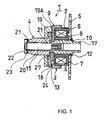
- Fig. 1 is a longitudinal section view of a toothed electromagnetic clutch according to one embodiment of this invention.
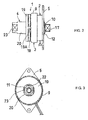
- Fig. 2 is a lateral view of a toothed electromagnetic clutch according to one embodiment of this invention.
- Fig 3 is a frontal view of a toothed electromagnetic clutch according to one embodiment of this invention.
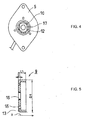
- Fig. 4 is a rear view of a toothed electromagnetic clutch according to one embodiment of this invention.
- Fig. 5 is longitudinal section view, which corresponds to line A-A as shown in Fig. 6, of a rotor ring according to one embodiment of this invention.
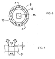
- Fig. 6 is a frontal view of a rotor ring according to one embodiment of this invention.
- Fig. 7 is a view showing an enlargement of the interlocking indentations of the rotor ring shown in Figure 5.
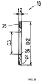
- Fig. 8 is a longitudinal section view of an armature according to one embodiment of this invention.
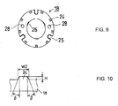
- Fig. 9 is a frontal view of the armature shown in Figure 8.
- Fig. 10 is a view showing an enlargement of the interlocking protuberances of the armature shown in Figure 8
- Toothed electromagnetic clutch 1 is comprised of field coil 2, rotor 3, and armature drive 4. Rotor 3 is connected to a rotating shaft of an electric motor.
- field coil 2 is comprised of baseboard 5, coil 6, housing 7, and bushing 8 Housing 7 accommodates coil 6, which is ring shaped.
- Baseboard 5 allows field coil 2 to be attached to an external frame or device, and bushing 8 connects field coil 2 to rotor 3 so as to allow relative rotation between field coil 2 and rotor 3.
- rotor 3 is comprised of cylindrical rotor ring 9, shaft 10, support shaft 11, snap ring 12, and rectangular coupler 17.
- Cylindrical rotor ring 9 extends over the outer periphery of housing 7, which is part of field coil assembly 2, with a specified clearance. Additionally, cylindrical rotor ring 9 includes rectangular aperture 16 by which it is fixedly attached to a rectangular portion of shaft 10.
- Shaft 10 extends through bushing 8. A cylindrical portion of shaft 10 and bushing 8 form a bearing that allows shaft 10 to be rotatably supported by field coil 2. Shaft 10 is fixed in the axial direction by the snap ring 12. Support shaft 11, which extends into armature drive 4, is press fit into one side of shaft 10.
- Rectangular coupler 17 is formed on the other side of shaft 10
- a rotating shaft (not shown) of a motor or similar device connects to shaft 10 through the use of rectangular coupler 17. Accordingly, rotor ring 9, shaft 10, and support shaft 11 rotate with the rotating shaft (not shown).
- interlocking indentations 13 are uniformly arranged at a central angle of 20° in the circumferential direction on the outer periphery of the outside end face of the bottom part of rotor ring 9, forming annular teeth.
- six arc-shaped long holes 15 are uniformly arranged at a central angle of 60° in the circumferential direction.
- rectangular aperture 16 is formed at the center of the bottom part of rotor ring 9.
- rotor ring 9 is formed by press working ("stamping") a 3.2 mm thick blank of cold rolled steel sheet (SPCE-SD), which is used for deep drawing.
- SPCE-SD cold rolled steel sheet
- the arrow mark X shown in Fig. 5 indicates the punching direction of long holes 15 and aperture 16.
- the surface of rotor ring 9 is hardened through the use a gas nitrocarbonizing method.
- armature drive 4 comprises ring-shaped armature 18, guide ring 19, cylindrical sleeve 20, bushing 21, snap ring 22, and clutch spring 27.
- Ring-shaped armature 18 faces opposite rotor ring 9.
- Guide ring 19 is affixed to and arranged behind armature 18 and it is affixed to cylindrical sleeve 20.
- Support shaft 11, which is part of rotor 3, is inserted in sleeve 20 via bushing 21 such that it is capable of rotating.
- Snap ring 22 fixes support shaft 11 in the axial direction.
- Spring 27 serves to keep ring shaped armature 18 away from rotor ring 9 when coil 6 is not energized.
- Rectangular coupler 23 is formed on the end of cylindrical sleeve 20 that is opposite to guide ring 19. Rectangular coupler 23 may be attached to a rotating shaft or if toothed electromagnetic clutch 1 is being used as a brake, then rectangular coupler 23 will be attached to a non rotating structure
- nine interlocking protuberances 24 are uniformly arranged in the circumferential direction at a central angle of 40° on the surface of armature 18 that faces rotor ring 9, forming annular teeth.
- the nine interlocking protuberances 24 are capable of engaging with the eighteen interlocking indentations 13 (annular teeth), which are formed on rotor ring 9.
- Three U-shaped grooves 25 are uniformly arranged at a central angle of 120° between interlocking protuberances 24 on the outer periphery of armature 18.
- Guide claws 19A which project from guide ring 19, fit into U-shaped grooves 25 and cause guide ring 19 to rotate with armature 18.
- Armature 18 can slide axially along guide claws 19A.
- Spring seat 26 is formed at the inner periphery edge part of armature 18.
- Clutch spring 27 engages with spring seat 26 to ordinarily maintain armature 18 away from the rotor ring 9 by the spring force.
- Guide holes 28 are provided in the armature 18 for the purpose of positioning U-shaped grooves 25 on guide claws 19A during assembly.
- armature 18 is formed by press working ("stamping") a 2.8 mm thick blank of cold rolled steel sheet (SPCE-SD), which is used for deep drawing.
- the armature 18 can, for example, be formed by the following type of stamping processes: (1) the annular blank is formed; (2) nine interlocking protuberances 24 and three spring seats 26 are formed in the blank; (3) three U-shaped grooves 25 and guide holes 28 are formed; (4) the inner surface of the U-shaped grooves 25 are formed; (5) the inner surface of the U-shaped grooves 25 are finished by surface pressing. Furthermore, surface-hardening treatment is conducted by the gas nitrocarbonizing method.
- toothed electromagnetic clutch is described with reference to Fig.1.
- coil 6 When coil 6 is energized, armature 18 is attracted towards rotor ring 9 by an electromagnetic force that is greater than the spring force of clutch spring 27. Armature 18 slides along guide claws 19A until it is united with the rotor ring 9.
- the nine interlocking protuberances 24 on armature 18 mesh with the eighteen interlocking indentations 13 on rotor ring 9.
- Interlocking indentations 13 apply torque to interlocking protuberances 24 thereby transmitting angular momentum and energy from rotor 3, including the kinetic energy and momentum of any rotating shaft or motor coupled to rotor 3 by rectangular coupler 17, to armature drive 4.
- Armature drive 4 transmits energy and momentum to any rotating shaft or non-rotating structure coupled to armature drive 4 through rectangular coupler 23.
- the nine interlocking protuberances 24 are meshed with the eighteen interlocking indentations 13, there is no occurrence of slippage between armature 18 and rotor ring 9. Accordingly, torque can be unfailingly applied.
- clutch spring 27 could be configured to apply a spring force that pushes armature 18 towards rotor ring 9 and field coil 2 could be positioned on armature drive 4 to apply an electromagnetic force that pulls armature 18 away from rotor ring 9 such that armature 18 and rotor ring 9 unite when coil 6 is deenergized.
Landscapes
- Engineering & Computer Science (AREA)
- General Engineering & Computer Science (AREA)
- Physics & Mathematics (AREA)
- Electromagnetism (AREA)
- Mechanical Engineering (AREA)
- Braking Arrangements (AREA)
Abstract
Description
Claims (25)
- A rotor ring for use in an electromagnetic clutch comprising:wherein said plurality of teeth are formed by stamping.a metallic ring having a plurality of teeth;
- The rotor ring of Claim 1 wherein:said metallic ring includes a central aperture.
- The rotor ring of Claim 1 or 2 wherein:said plurality of teeth further comprises of indentations in said metallic ring.
- The rotor ring of Claim 3 wherein:said indentations have a depth equal to 0.8 millimeters, a width equal to 2.8 millimeters, and a pressure angle equal to 23 degrees.
- The rotor ring of any preceding claim wherein:said metallic ring has a flat surface with an outer perimeter; and said plurality of teeth are placed uniformly along said outer perimeter.
- The rotor ring of any preceding claim wherein:said metallic ring includes a plurality of arc-shaped long holes that are placed uniformly on said flat surface internal to and adjacent to said plurality of teeth.
- The rotor ring of any preceding claim comprising:a cylindrical surface integral to and extending from said outer perimeter of the flat surface of the metallic ring.
- The rotor ring of any preceding claim wherein:said metallic ring has a diameter equal to 50 millimeters;said metallic ring has a thickness equal to 3.2 millimeters;and said cylindrical surface has a height of 12.3 millimeters.
- A method of manufacturing a rotor ring comprising the step of:stamping a ring shaped blank of metal to form teeth on said blank.
- The method of Claim 9 further comprising the step of:surface hardening said ring shaped blank after it has been stamped.
- An armature for use in an electromagnetic clutch comprising:wherein said plurality of teeth are formed by stamping.a metallic ring having a plurality of teeth;
- The armature of Claim 11 wherein:said metallic ring includes a circular central aperture.
- The armature of Claim 12 wherein:said metallic ring has a diameter equal to 46 millimeters;said metallic ring has a thickness equal to 2.8 millimeters;and said central aperture has a diameter of 24 millimeters.
- The armature of any of Claims 11 to 13 wherein:said metallic ring has a flat surface with an outer perimeter; and said plurality of teeth are placed uniformly along said outer perimeter.
- The armature of any of Claims 11 to 14 wherein:said metallic ring includes two holes that are placed uniformly on said flat surface internal to said plurality of teeth.
- The armature of any of Claims 11 to 15 further wherein:a plurality of u-shaped openings are uniformly placed along the outer perimeter of the flat surface of the metallic ring in between teeth of said plurality of teeth.
- The armature of any of Claims 11 to 16 wherein:said plurality of teeth further comprises of protrusions from said metallic ring.
- The armature of Claim 17 wherein:said protuberances have a height equal to 0.7 millimeters, a width equal to 2.6 millimeters, and a pressure angle equal to 23 degrees.
- A method of manufacturing an armature comprising the step of:stamping a ring shaped blank of metal to form teeth on said blank.
- The method of Claim 19 further comprising the step of:surface hardening said ring shaped blank after it has been stamped.
- A method of manufacturing an armature comprising the steps of:(1) forming an annular blank;(2) stamping nine protuberances and three spring seats in the blank;(3) stamping three U-shaped grooves and two guide holes in the blank;(4) finishing the inner surface of the U-shaped grooves by surface pressing.(5) surface hardening the annular blank.
- The method of Claim 21 wherein:the annular blank is comprised of cold rolled steel sheet.
- A toothed electromagnetic clutch comprising:an armature assembly having a stamped armature;a rotor having a stamped rotor ring; anda field coil.
- The toothed electromagnetic clutch of Claim 23 wherein:said stamped armature has a plurality of protrusions; andsaid stamped rotor has a plurality of indentations.
- A toothed electromagnetic clutch brake comprising:wherein said armature assembly is coupled to a non-rotating structure.an armature assembly having a stamped armature;a rotor having a stamped rotor ring; anda field coil;
Applications Claiming Priority (2)
| Application Number | Priority Date | Filing Date | Title |
|---|---|---|---|
| JP2002165562 | 2002-06-06 | ||
| JP2002165562A JP2004011744A (en) | 2002-06-06 | 2002-06-06 | Toothed electromagnetic clutch brake |
Publications (2)
| Publication Number | Publication Date |
|---|---|
| EP1369612A2 true EP1369612A2 (en) | 2003-12-10 |
| EP1369612A3 EP1369612A3 (en) | 2005-04-27 |
Family
ID=29545821
Family Applications (1)
| Application Number | Title | Priority Date | Filing Date |
|---|---|---|---|
| EP03253556A Withdrawn EP1369612A3 (en) | 2002-06-06 | 2003-06-05 | Toothed electromagnetic clutch-brake |
Country Status (3)
| Country | Link |
|---|---|
| US (1) | US6910564B2 (en) |
| EP (1) | EP1369612A3 (en) |
| JP (1) | JP2004011744A (en) |
Cited By (1)
| Publication number | Priority date | Publication date | Assignee | Title |
|---|---|---|---|---|
| CN102287458A (en) * | 2011-07-26 | 2011-12-21 | 王万年 | End tooth electromagnetic clutch |
Families Citing this family (7)
| Publication number | Priority date | Publication date | Assignee | Title |
|---|---|---|---|---|
| US7311183B2 (en) * | 2005-03-28 | 2007-12-25 | Black Jr Robert A | Adjustable clutch brake and method of use thereof |
| JP5264323B2 (en) * | 2008-07-01 | 2013-08-14 | 日本電産サンキョー株式会社 | motor |
| JP5264322B2 (en) * | 2008-07-01 | 2013-08-14 | 日本電産サンキョー株式会社 | motor |
| US8646586B2 (en) | 2010-06-15 | 2014-02-11 | John Catrinta | Torque-limiting clutch brake |
| EP2899421A3 (en) * | 2014-01-27 | 2016-02-17 | Dana Automotive Systems Group , LLC | Electromagnetic connect/disconnect system for a vehicle |
| US10436258B2 (en) | 2014-07-13 | 2019-10-08 | Dana Automotive Systems Group, Llc | Method and system for latching an actuator |
| US10323699B2 (en) | 2015-07-02 | 2019-06-18 | Dana Automotive Systems Group, Llc | Electromagnetic connect/disconnect system for a vehicle |
Family Cites Families (14)
| Publication number | Priority date | Publication date | Assignee | Title |
|---|---|---|---|---|
| US1756907A (en) * | 1928-06-09 | 1930-04-29 | Goodwin Hall J | Electromagnetic clutch |
| US1847926A (en) * | 1929-02-28 | 1932-03-01 | Monroe Calculating Machine | Method of forming internal and crown gears |
| GB394863A (en) * | 1932-08-19 | 1933-07-06 | Landis & Gyr A I G | An improved synchronous electric motor |
| GB539451A (en) * | 1939-12-11 | 1941-09-11 | Stewart Warner Corp | Electrical speedometers |
| GB1210235A (en) * | 1967-05-16 | 1970-10-28 | Mullard Ltd | Improvements in or relating to electric motors |
| US3672042A (en) * | 1971-04-26 | 1972-06-27 | Eaton Corp | Method of making pole members |
| US3917042A (en) * | 1974-04-29 | 1975-11-04 | Hubert Wayne Summa | Magnetic clutch |
| US4010832A (en) * | 1975-06-24 | 1977-03-08 | Facet Enterprises, Inc. | Return spring for teeth clutch -- two stage force |
| DE2917548A1 (en) * | 1979-04-30 | 1980-11-06 | Agfa Gevaert Ag | ELECTROMAGNETIC, SLIP RINGLESS CLUTCH |
| US4566566A (en) * | 1983-09-19 | 1986-01-28 | Societe Alsacienne De Construction De Material Textile | Device for temporarily uncoupling two coaxial rotating elements |
| US5035310A (en) * | 1986-07-23 | 1991-07-30 | Michael Meyerle | Clutch, particularly for automatic transmission for automotive vehicles |
| DE19832390A1 (en) * | 1998-07-18 | 1999-03-04 | Sbs Sondermaschinen Gmbh | Transverse flux electrical machine e.g. for vehicle generator and wind generator |
| JP4472797B2 (en) * | 1998-10-15 | 2010-06-02 | 株式会社ピーエヌ | Metal product pressing and progressive processing |
| EP1135845B8 (en) * | 1998-12-03 | 2005-09-14 | C-Mac Invotronics Inc. | Power actuator having an electromagnetic clutch assembly |
-
2002
- 2002-06-06 JP JP2002165562A patent/JP2004011744A/en active Pending
-
2003
- 2003-05-30 US US10/449,964 patent/US6910564B2/en not_active Expired - Fee Related
- 2003-06-05 EP EP03253556A patent/EP1369612A3/en not_active Withdrawn
Cited By (1)
| Publication number | Priority date | Publication date | Assignee | Title |
|---|---|---|---|---|
| CN102287458A (en) * | 2011-07-26 | 2011-12-21 | 王万年 | End tooth electromagnetic clutch |
Also Published As
| Publication number | Publication date |
|---|---|
| JP2004011744A (en) | 2004-01-15 |
| US6910564B2 (en) | 2005-06-28 |
| EP1369612A3 (en) | 2005-04-27 |
| US20040035665A1 (en) | 2004-02-26 |
Similar Documents
| Publication | Publication Date | Title |
|---|---|---|
| US6193038B1 (en) | One-way clutch and method for making same | |
| EP2733374B1 (en) | Clutch plate, clutch unit and driving force transmission system | |
| US10364850B2 (en) | Clutch mechanism | |
| JP6044754B2 (en) | Clutch plate and manufacturing method thereof | |
| US11049634B2 (en) | Electromagnetic actuator and connection/disconnection apparatus | |
| US6910564B2 (en) | Toothed electromagnetic clutch brake | |
| EP1000275B1 (en) | One-piece flywheel having outer ring gear portion, and process of manufacturing the same | |
| KR101749477B1 (en) | Manufacturing method of hub for electromagnetic clutch | |
| JP3843960B2 (en) | Starter | |
| CN105492793B (en) | Operating equipment for clutches | |
| US5718311A (en) | Cold formed torque converter cover | |
| EP3947062B1 (en) | Miniature brake and method of assembly | |
| JP2009133382A (en) | Cyclo reducer | |
| JP2009133382A6 (en) | Cyclo reducer | |
| CN112513487B (en) | Ramp actuator and method for producing a ramp disk | |
| JPH0625719Y2 (en) | Electromagnetic clutch / brake | |
| US20180031048A1 (en) | Backing Plate Providing Axial Stiffness | |
| JPH0623781Y2 (en) | Automatic gap adjusting device for electromagnetic coupling device | |
| JP2025144949A (en) | Rotation Transmission Device | |
| JP3484273B2 (en) | Method of manufacturing backing plate for friction engagement device | |
| KR101390623B1 (en) | Starter | |
| JP2008067555A (en) | Rotor assembly and manufacturing method therefor | |
| KR101485556B1 (en) | Electromagnetic clutch for industrial machines | |
| JPS6314105Y2 (en) | ||
| JP2005054907A (en) | Non-excitation electromagnetic brake |
Legal Events
| Date | Code | Title | Description |
|---|---|---|---|
| PUAI | Public reference made under article 153(3) epc to a published international application that has entered the european phase |
Free format text: ORIGINAL CODE: 0009012 |
|
| AK | Designated contracting states |
Kind code of ref document: A2 Designated state(s): AT BE BG CH CY CZ DE DK EE ES FI FR GB GR HU IE IT LI LU MC NL PT RO SE SI SK TR |
|
| AX | Request for extension of the european patent |
Extension state: AL LT LV MK |
|
| PUAL | Search report despatched |
Free format text: ORIGINAL CODE: 0009013 |
|
| AK | Designated contracting states |
Kind code of ref document: A3 Designated state(s): AT BE BG CH CY CZ DE DK EE ES FI FR GB GR HU IE IT LI LU MC NL PT RO SE SI SK TR |
|
| AX | Request for extension of the european patent |
Extension state: AL LT LV MK |
|
| 17P | Request for examination filed |
Effective date: 20051025 |
|
| AKX | Designation fees paid |
Designated state(s): AT BE BG CH CY CZ DE DK EE ES FI FR GB GR HU IE IT LI LU MC NL PT RO SE SI SK TR |
|
| STAA | Information on the status of an ep patent application or granted ep patent |
Free format text: STATUS: THE APPLICATION IS DEEMED TO BE WITHDRAWN |
|
| 18D | Application deemed to be withdrawn |
Effective date: 20060411 |