EP1369609A2 - Constant velocity joints - Google Patents
Constant velocity joints Download PDFInfo
- Publication number
- EP1369609A2 EP1369609A2 EP02026192A EP02026192A EP1369609A2 EP 1369609 A2 EP1369609 A2 EP 1369609A2 EP 02026192 A EP02026192 A EP 02026192A EP 02026192 A EP02026192 A EP 02026192A EP 1369609 A2 EP1369609 A2 EP 1369609A2
- Authority
- EP
- European Patent Office
- Prior art keywords
- housing
- constant velocity
- coupled
- velocity joint
- rollers
- Prior art date
- Legal status (The legal status is an assumption and is not a legal conclusion. Google has not performed a legal analysis and makes no representation as to the accuracy of the status listed.)
- Withdrawn
Links
Images


Classifications
-
- F—MECHANICAL ENGINEERING; LIGHTING; HEATING; WEAPONS; BLASTING
- F16—ENGINEERING ELEMENTS AND UNITS; GENERAL MEASURES FOR PRODUCING AND MAINTAINING EFFECTIVE FUNCTIONING OF MACHINES OR INSTALLATIONS; THERMAL INSULATION IN GENERAL
- F16D—COUPLINGS FOR TRANSMITTING ROTATION; CLUTCHES; BRAKES
- F16D3/00—Yielding couplings, i.e. with means permitting movement between the connected parts during the drive
- F16D3/16—Universal joints in which flexibility is produced by means of pivots or sliding or rolling connecting parts
- F16D3/20—Universal joints in which flexibility is produced by means of pivots or sliding or rolling connecting parts one coupling part entering a sleeve of the other coupling part and connected thereto by sliding or rolling members
- F16D3/202—Universal joints in which flexibility is produced by means of pivots or sliding or rolling connecting parts one coupling part entering a sleeve of the other coupling part and connected thereto by sliding or rolling members one coupling part having radially projecting pins, e.g. tripod joints
-
- F—MECHANICAL ENGINEERING; LIGHTING; HEATING; WEAPONS; BLASTING
- F16—ENGINEERING ELEMENTS AND UNITS; GENERAL MEASURES FOR PRODUCING AND MAINTAINING EFFECTIVE FUNCTIONING OF MACHINES OR INSTALLATIONS; THERMAL INSULATION IN GENERAL
- F16D—COUPLINGS FOR TRANSMITTING ROTATION; CLUTCHES; BRAKES
- F16D3/00—Yielding couplings, i.e. with means permitting movement between the connected parts during the drive
- F16D3/16—Universal joints in which flexibility is produced by means of pivots or sliding or rolling connecting parts
- F16D3/20—Universal joints in which flexibility is produced by means of pivots or sliding or rolling connecting parts one coupling part entering a sleeve of the other coupling part and connected thereto by sliding or rolling members
- F16D3/202—Universal joints in which flexibility is produced by means of pivots or sliding or rolling connecting parts one coupling part entering a sleeve of the other coupling part and connected thereto by sliding or rolling members one coupling part having radially projecting pins, e.g. tripod joints
- F16D3/207—Universal joints in which flexibility is produced by means of pivots or sliding or rolling connecting parts one coupling part entering a sleeve of the other coupling part and connected thereto by sliding or rolling members one coupling part having radially projecting pins, e.g. tripod joints the pins extending radially inwardly from the coupling part
Definitions
- the present invention relates to a constant velocity joint, and more particularly, to a tripod constant velocity joint for use in a driving axle of a vehicle wherein shudder can be efficiently reduced in the vehicle by installing several assemblies of a trunnion, a bearing and a roller within a housing so that a sliding friction force between the roller and the trunnion is transmitted not to the driving axle but to the housing and then is cancelled in a transmission side.
- a constant velocity joint is a joint for allowing driving and driven axles to be smoothly operated at an identical velocity even though an intersection angle between the driving and driven axles is increased.
- the constant velocity joint is spline-coupled to a driving axle of a front wheel drive vehicle or a rear differential side gear in an independent suspension system.
- FIG. 1 is a perspective view of a conventional driving axle of a vehicle.
- the driving axle 1 of the vehicle is generally provided with two constant velocity joints 2 at a portion coupled to a transmission side and a portion coupled to a disk 3.
- a double offset joint or tripod joint is used at the transmission side, whereas a birfield joint is used at the disk side.
- FIG. 2 is a perspective view of a conventional tripod joint.
- a roller 7 is assembled with a trunnion 5 with a bearing 6 interposed therebetween.
- the assemblies of the roller, the trunnion and the bearing are installed equiangularly at three positions within a housing 4 coupled to the transmission side.
- the driving axle 1 is coupled into the housing 4.
- a driving force from the transmission side is transmitted to the driving axle at a constant velocity.
- the constant velocity joint is installed to the aforementioned transmission side or rear differential side gear.
- the roller 7 is rotated. Consequently, the driving axle 1 is also rotated.
- shudder may be produced in the vehicle due to an axial force transmitted to the driving axle 1.
- f2 is a friction force between the roller 7 and a groove of the housing 4 in a direction of the trunnion 5
- f3 is a friction force between the roller 7 and the trunnion 5.
- a shudderless joint may be utilized so that the axial force can be considerably reduced.
- use of only the shudderless joint cannot fundamentally solve the problem. That is, the shudderless joint also has a constitution in which a force component of f3 corresponding to the friction force between the roller and the trunnion is transmitted directly to the driving axle. Therefore, the axial force cannot be completely reduced.
- the present invention is conceived to solve the problems in the prior art. Accordingly, it is an object of the present invention to provide a constant velocity joint wherein friction forces between bearings, rollers and trunnions can be reduced, shudder of a vehicle can be effectively reduced by causing the sliding friction forces of the rollers with the trunnions to be transmitted not to a driving axle but to a housing so that the friction forces can be cancelled in a transmission side, a shudderless joint need not be employed, and no additional spline processing is required since grooves formed in an insert can be manufactured through a forging process.
- a constant velocity joint which comprises a housing made in the form of a cylindrical shell, trunnions installed at three positions equiangularly on an inner circumferential surface of the housing; bearings coupled to the respective trunnions, rollers coupled to the outsides of the respective bearings, and a driving axle in which an insert with three grooves formed equiangularly on an outer periphery thereof is coupled to an end of the axle so that the axle can be coupled into the housing with the rollers installed therein.
- FIG. 5 is a perspective view of a constant velocity joint according to a preferred embodiment of the present invention
- FIG. 6 is a side view of the constant velocity joint according to the preferred embodiment of the present invention
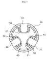
- FIG. 7 is a sectional view taken along line A-A of FIG. 6.
- the constant velocity joint of the present invention comprises a housing 10 made in the form of a cylindrical shell, trunnions 20 installed at three positions equiangularly on an inner circumferential surface of the housing 10, bearings 30 coupled to the respective trunnions, rollers 40 coupled to the outsides of the respective bearings 30, and a driving axle 50 in which an insert 52 with grooves 51 formed at three positions equiangularly on an outer periphery thereof is coupled to an end of the axle so that the axle can be coupled into the housing 10 with the rollers 40 installed therein.
- rollers 40 and contact surfaces of grooves 51 with the rollers 40 are formed to be spherical, a friction force due to rolling action of each roller 40 can be minimized so that any axial motions are not produced in the driving axle 50.
- the trunnions 20 are fitted into holes formed equiangularly along a circumference of the housing 10, and then fixed thereto through a press-fit process or with an adhesive. Thereafter, the bearings 30 and the rollers 40 are sequentially installed around the trunnions 20 fixed to the housing 10, respectively.
- a needle bearing in the form of the cylindrical shell for surrounding the trunnion 20 is used as the bearing 30.
- each of the trunnions 20 further comprises a spacer 21 for preventing the bearing 30 from coming into contact with the relevant groove 51 of the insert 50.
- the present invention is characterized in that in the constant velocity joint, the trunnions 20, bearings 30, and rollers 40 are mounted to the housing 10.
- the sliding friction force with respect to the trunnion 20 is basically transferred to the housing 10 rather than the driving axle 50, so that it can be cancelled in a transmission side.
- a friction force between the roller 40 and the bearing 30, a rotational friction force between the roller 40 and the housing with respect to an axis of the trunnion 20, and an axial (linear) friction force between the roller 40 and the housing with respect to the axis of the trunnion 20 is decreased, and a spin force of the roller 40 is also reduced.
- the constant velocity of the present invention has a superior effect in reducing the axial force as described above, the expensive shudderless joint need not be used.
- the shudderless joint is employed together with the constant velocity joint of the present invention, an effect of reduction in the axial force can be further improved.
- the grooves 51 formed in the insert 52 can be manufactured through a general forging process. Thus, any additional spline processing is not needed.
- the friction forces between the bearing, the roller and the trunnion can be reduced.
- the shudder can be effectively reduced by causing the sliding friction force of the roller with respect to the trunnion to be transmitted not to the driving axle but to the housing so that the friction force can be cancelled in the transmission side.
- the shudderless joint need not be employed.
- no additional spline processing is required since the grooves formed in the insert can be manufactured through the forging process.
Landscapes
- Engineering & Computer Science (AREA)
- General Engineering & Computer Science (AREA)
- Mechanical Engineering (AREA)
- Friction Gearing (AREA)
- Rolling Contact Bearings (AREA)
Abstract
Description
Claims (4)
- A constant velocity joint, comprising:a housing made in the form of a cylindrical shell;trunnions installed at three positions equiangularly on an inner circumferential surface of the housing;bearings coupled to the respective trunnions,rollers coupled to the outsides of the respective bearings, anda driving axle in which an insert with three grooves formed equiangularly on an outer periphery thereof is coupled to an end of the axle so that the axle can be coupled into the housing with the rollers installed therein.
- The constant velocity joint as claimed in claim 1, wherein rolling surfaces of the rollers and contact surfaces of the grooves with the rollers are formed to be spherical.
- The constant velocity joint as claimed in claim 1, wherein the trunnions are fitted into holes formed equiangularly along a circumference of the housing and then fixed thereto through a press-fit process or with an adhesive.
- The constant velocity joint as claimed in claim 1, wherein each of the trunnions further includes a spacer for preventing the bearing from coming into contact with the relevant groove of the insert.
Applications Claiming Priority (2)
| Application Number | Priority Date | Filing Date | Title |
|---|---|---|---|
| KR2002031377 | 2002-06-04 | ||
| KR10-2002-0031377A KR100461259B1 (en) | 2002-06-04 | 2002-06-04 | Constant velocity joints |
Publications (2)
| Publication Number | Publication Date |
|---|---|
| EP1369609A2 true EP1369609A2 (en) | 2003-12-10 |
| EP1369609A3 EP1369609A3 (en) | 2004-09-01 |
Family
ID=29546394
Family Applications (1)
| Application Number | Title | Priority Date | Filing Date |
|---|---|---|---|
| EP02026192A Withdrawn EP1369609A3 (en) | 2002-06-04 | 2002-11-25 | Constant velocity joints |
Country Status (4)
| Country | Link |
|---|---|
| US (1) | US20030224860A1 (en) |
| EP (1) | EP1369609A3 (en) |
| JP (1) | JP2004011907A (en) |
| KR (1) | KR100461259B1 (en) |
Families Citing this family (4)
| Publication number | Priority date | Publication date | Assignee | Title |
|---|---|---|---|---|
| US7097565B2 (en) * | 2004-08-09 | 2006-08-29 | Torque-Traction Technologies, Llc | Fixed-center articulating constant velocity joint |
| CN104061249A (en) * | 2014-06-27 | 2014-09-24 | 苏州市海神达机械科技有限公司 | Universal extensible joint |
| JP6719912B2 (en) * | 2016-01-21 | 2020-07-08 | 昌弘 町田 | Rotation transmission mechanism |
| JP7114129B1 (en) * | 2021-12-07 | 2022-08-08 | 株式会社クロイツ | Universal joint mechanism, tool joint and tool drive unit |
Family Cites Families (12)
| Publication number | Priority date | Publication date | Assignee | Title |
|---|---|---|---|---|
| FR1250605A (en) * | 1959-12-02 | 1961-01-13 | Transmission seal | |
| US3877251A (en) * | 1973-06-15 | 1975-04-15 | Wahlmark Systems | Universal joint system |
| JPS5941048B2 (en) * | 1975-04-23 | 1984-10-04 | ユニ − カルダン アクチエンゲゼルシヤフト | synchronous rotary joint |
| JPS5445442A (en) * | 1977-09-19 | 1979-04-10 | Honda Motor Co Ltd | Sliding type equal-speed universal joint |
| JPS5467841A (en) * | 1977-11-09 | 1979-05-31 | Toyota Motor Corp | Outer part of equal-speed universal joint and its manufacturing process |
| DE3041855C2 (en) * | 1980-11-06 | 1984-07-05 | Löhr & Bromkamp GmbH, 6050 Offenbach | Storage arrangement |
| FR2506872B1 (en) * | 1981-06-01 | 1986-05-09 | Glaenzer Spicer Sa | TELESCOPIC HOMOCINETIC JOINT |
| FR2548595B1 (en) * | 1983-07-04 | 1988-05-27 | Glaenzer Spicer Sa | VEHICLE DRIVE WHEEL HUB ASSEMBLY |
| FR2699620B1 (en) * | 1992-12-17 | 1995-03-17 | Gkn Glaenzer Spicer | Articulated joint with rollers. |
| JP3692663B2 (en) * | 1996-10-31 | 2005-09-07 | 日本精工株式会社 | Tripod type constant velocity joint |
| JP3982863B2 (en) * | 1997-01-27 | 2007-09-26 | 日本精工株式会社 | Tripod type constant velocity joint |
| JP4178613B2 (en) * | 1998-09-02 | 2008-11-12 | 日本精工株式会社 | Tripod type constant velocity joint |
-
2002
- 2002-06-04 KR KR10-2002-0031377A patent/KR100461259B1/en not_active Expired - Fee Related
- 2002-11-25 EP EP02026192A patent/EP1369609A3/en not_active Withdrawn
- 2002-11-26 US US10/306,652 patent/US20030224860A1/en not_active Abandoned
- 2002-11-29 JP JP2002347409A patent/JP2004011907A/en active Pending
Also Published As
| Publication number | Publication date |
|---|---|
| US20030224860A1 (en) | 2003-12-04 |
| KR100461259B1 (en) | 2004-12-10 |
| JP2004011907A (en) | 2004-01-15 |
| EP1369609A3 (en) | 2004-09-01 |
| KR20030094557A (en) | 2003-12-18 |
Similar Documents
| Publication | Publication Date | Title |
|---|---|---|
| US6582151B2 (en) | Driving axle assembly | |
| KR101378830B1 (en) | Constant velocity joint attachment method | |
| EP2594821B1 (en) | Ball type constant velocity joint for vehicle | |
| EP1372986B1 (en) | Wheel drive unit | |
| US6764406B2 (en) | Constant velocity joint of tripod type | |
| EP0608339B1 (en) | Anti-shudder tripod constant velocity joint | |
| GB2295365A (en) | Wheel bearing/constant-velocity universal joint assembly | |
| US8142292B2 (en) | Universal joint with trunnion shaft seal assembly | |
| CA1250763A (en) | Non-differential drive axle | |
| JPH1191307A (en) | Hub unit | |
| JP2009511839A (en) | Direct torque flow connection with optimum ratio in mounting method | |
| US5643091A (en) | Stroking constant velocity universal joint having low stroke load | |
| US20060079336A1 (en) | Tripod-type constant velocity joint | |
| US20030224860A1 (en) | Constant velocity joints | |
| CN115163682A (en) | Spherical surface matching structure of large-angle universal joint assembly and universal joint | |
| CN106555824A (en) | A kind of rzeppa joint, card gear and automobile | |
| US20250052284A1 (en) | Propeller shaft | |
| EP2937586B1 (en) | Fixed ball type joint for vehicle | |
| JP2583634Y2 (en) | Automotive tripod type constant velocity joint | |
| KR102301016B1 (en) | Constant velocity joint | |
| KR20060060342A (en) | Tripod constant velocity joint | |
| WO2026058629A1 (en) | Tripod-type constant-velocity joint | |
| CN120720340A (en) | Outer coupling member for constant velocity universal joint and fixed constant velocity universal joint equipped with the same | |
| Park | Multi-roller balls for constant velocity joints: Innovative solution for better mechanical efficiency and durability | |
| JP2002054721A (en) | Drive shaft spacer support structure |
Legal Events
| Date | Code | Title | Description |
|---|---|---|---|
| PUAI | Public reference made under article 153(3) epc to a published international application that has entered the european phase |
Free format text: ORIGINAL CODE: 0009012 |
|
| AK | Designated contracting states |
Kind code of ref document: A2 Designated state(s): AT BE BG CH CY CZ DE DK EE ES FI FR GB GR IE IT LI LU MC NL PT SE SK TR |
|
| AX | Request for extension of the european patent |
Extension state: AL LT LV MK RO SI |
|
| PUAL | Search report despatched |
Free format text: ORIGINAL CODE: 0009013 |
|
| AK | Designated contracting states |
Kind code of ref document: A3 Designated state(s): AT BE BG CH CY CZ DE DK EE ES FI FR GB GR IE IT LI LU MC NL PT SE SK TR |
|
| AX | Request for extension of the european patent |
Extension state: AL LT LV MK RO SI |
|
| AKX | Designation fees paid | ||
| REG | Reference to a national code |
Ref country code: DE Ref legal event code: 8566 |
|
| DBV | Designated contracting states (deleted) | ||
| STAA | Information on the status of an ep patent application or granted ep patent |
Free format text: STATUS: THE APPLICATION IS DEEMED TO BE WITHDRAWN |
|
| 18D | Application deemed to be withdrawn |
Effective date: 20050203 |