EP1369362A1 - Article feeding device - Google Patents
Article feeding device Download PDFInfo
- Publication number
- EP1369362A1 EP1369362A1 EP01273381A EP01273381A EP1369362A1 EP 1369362 A1 EP1369362 A1 EP 1369362A1 EP 01273381 A EP01273381 A EP 01273381A EP 01273381 A EP01273381 A EP 01273381A EP 1369362 A1 EP1369362 A1 EP 1369362A1
- Authority
- EP
- European Patent Office
- Prior art keywords
- product
- products
- bagged
- transport
- transport means
- Prior art date
- Legal status (The legal status is an assumption and is not a legal conclusion. Google has not performed a legal analysis and makes no representation as to the accuracy of the status listed.)
- Granted
Links
Images


Classifications
-
- B—PERFORMING OPERATIONS; TRANSPORTING
- B65—CONVEYING; PACKING; STORING; HANDLING THIN OR FILAMENTARY MATERIAL
- B65G—TRANSPORT OR STORAGE DEVICES, e.g. CONVEYORS FOR LOADING OR TIPPING, SHOP CONVEYOR SYSTEMS OR PNEUMATIC TUBE CONVEYORS
- B65G47/00—Article or material-handling devices associated with conveyors; Methods employing such devices
- B65G47/22—Devices influencing the relative position or the attitude of articles during transit by conveyors
- B65G47/26—Devices influencing the relative position or the attitude of articles during transit by conveyors arranging the articles, e.g. varying spacing between individual articles
- B65G47/28—Devices influencing the relative position or the attitude of articles during transit by conveyors arranging the articles, e.g. varying spacing between individual articles during transit by a single conveyor
-
- B—PERFORMING OPERATIONS; TRANSPORTING
- B65—CONVEYING; PACKING; STORING; HANDLING THIN OR FILAMENTARY MATERIAL
- B65B—MACHINES, APPARATUS OR DEVICES FOR, OR METHODS OF, PACKAGING ARTICLES OR MATERIALS; UNPACKING
- B65B35/00—Supplying, feeding, arranging or orientating articles to be packaged
- B65B35/10—Feeding, e.g. conveying, single articles
- B65B35/24—Feeding, e.g. conveying, single articles by endless belts or chains
- B65B35/243—Feeding, e.g. conveying, single articles by endless belts or chains using cooperating conveyors engaging the articles simultaneously
-
- B—PERFORMING OPERATIONS; TRANSPORTING
- B65—CONVEYING; PACKING; STORING; HANDLING THIN OR FILAMENTARY MATERIAL
- B65B—MACHINES, APPARATUS OR DEVICES FOR, OR METHODS OF, PACKAGING ARTICLES OR MATERIALS; UNPACKING
- B65B35/00—Supplying, feeding, arranging or orientating articles to be packaged
- B65B35/56—Orientating, i.e. changing the attitude of, articles, e.g. of non-uniform cross-section
-
- B—PERFORMING OPERATIONS; TRANSPORTING
- B65—CONVEYING; PACKING; STORING; HANDLING THIN OR FILAMENTARY MATERIAL
- B65B—MACHINES, APPARATUS OR DEVICES FOR, OR METHODS OF, PACKAGING ARTICLES OR MATERIALS; UNPACKING
- B65B51/00—Devices for, or methods of, sealing or securing package folds or closures; Devices for gathering or twisting wrappers, or necks of bags
- B65B51/32—Cooling, or cooling and pressing, package closures after heat-sealing
-
- B—PERFORMING OPERATIONS; TRANSPORTING
- B65—CONVEYING; PACKING; STORING; HANDLING THIN OR FILAMENTARY MATERIAL
- B65B—MACHINES, APPARATUS OR DEVICES FOR, OR METHODS OF, PACKAGING ARTICLES OR MATERIALS; UNPACKING
- B65B61/00—Auxiliary devices, not otherwise provided for, for operating on sheets, blanks, webs, binding material, containers or packages
- B65B61/24—Auxiliary devices, not otherwise provided for, for operating on sheets, blanks, webs, binding material, containers or packages for shaping or reshaping completed packages
-
- B—PERFORMING OPERATIONS; TRANSPORTING
- B65—CONVEYING; PACKING; STORING; HANDLING THIN OR FILAMENTARY MATERIAL
- B65B—MACHINES, APPARATUS OR DEVICES FOR, OR METHODS OF, PACKAGING ARTICLES OR MATERIALS; UNPACKING
- B65B63/00—Auxiliary devices, not otherwise provided for, for operating on articles or materials to be packaged
- B65B63/02—Auxiliary devices, not otherwise provided for, for operating on articles or materials to be packaged for compressing or compacting articles or materials prior to wrapping or insertion in containers or receptacles
- B65B63/026—Auxiliary devices, not otherwise provided for, for operating on articles or materials to be packaged for compressing or compacting articles or materials prior to wrapping or insertion in containers or receptacles for compressing by feeding articles through a narrowing space
-
- B—PERFORMING OPERATIONS; TRANSPORTING
- B65—CONVEYING; PACKING; STORING; HANDLING THIN OR FILAMENTARY MATERIAL
- B65G—TRANSPORT OR STORAGE DEVICES, e.g. CONVEYORS FOR LOADING OR TIPPING, SHOP CONVEYOR SYSTEMS OR PNEUMATIC TUBE CONVEYORS
- B65G15/00—Conveyors having endless load-conveying surfaces, i.e. belts and like continuous members, to which tractive effort is transmitted by means other than endless driving elements of similar configuration
- B65G15/10—Conveyors having endless load-conveying surfaces, i.e. belts and like continuous members, to which tractive effort is transmitted by means other than endless driving elements of similar configuration comprising two or more co-operating endless surfaces with parallel longitudinal axes, or a multiplicity of parallel elements, e.g. ropes defining an endless surface
- B65G15/12—Conveyors having endless load-conveying surfaces, i.e. belts and like continuous members, to which tractive effort is transmitted by means other than endless driving elements of similar configuration comprising two or more co-operating endless surfaces with parallel longitudinal axes, or a multiplicity of parallel elements, e.g. ropes defining an endless surface with two or more endless belts
- B65G15/14—Conveyors having endless load-conveying surfaces, i.e. belts and like continuous members, to which tractive effort is transmitted by means other than endless driving elements of similar configuration comprising two or more co-operating endless surfaces with parallel longitudinal axes, or a multiplicity of parallel elements, e.g. ropes defining an endless surface with two or more endless belts the load being conveyed between the belts
-
- B—PERFORMING OPERATIONS; TRANSPORTING
- B65—CONVEYING; PACKING; STORING; HANDLING THIN OR FILAMENTARY MATERIAL
- B65G—TRANSPORT OR STORAGE DEVICES, e.g. CONVEYORS FOR LOADING OR TIPPING, SHOP CONVEYOR SYSTEMS OR PNEUMATIC TUBE CONVEYORS
- B65G47/00—Article or material-handling devices associated with conveyors; Methods employing such devices
- B65G47/22—Devices influencing the relative position or the attitude of articles during transit by conveyors
- B65G47/26—Devices influencing the relative position or the attitude of articles during transit by conveyors arranging the articles, e.g. varying spacing between individual articles
- B65G47/30—Devices influencing the relative position or the attitude of articles during transit by conveyors arranging the articles, e.g. varying spacing between individual articles during transit by a series of conveyors
- B65G47/31—Devices influencing the relative position or the attitude of articles during transit by conveyors arranging the articles, e.g. varying spacing between individual articles during transit by a series of conveyors by varying the relative speeds of the conveyors forming the series
-
- B—PERFORMING OPERATIONS; TRANSPORTING
- B65—CONVEYING; PACKING; STORING; HANDLING THIN OR FILAMENTARY MATERIAL
- B65B—MACHINES, APPARATUS OR DEVICES FOR, OR METHODS OF, PACKAGING ARTICLES OR MATERIALS; UNPACKING
- B65B1/00—Packaging fluent solid material, e.g. powders, granular or loose fibrous material, loose masses of small articles, in individual containers or receptacles, e.g. bags, sacks, boxes, cartons, cans, or jars
- B65B1/30—Devices or methods for controlling or determining the quantity or quality or the material fed or filled
- B65B1/46—Check-weighing of filled containers or receptacles
-
- B—PERFORMING OPERATIONS; TRANSPORTING
- B65—CONVEYING; PACKING; STORING; HANDLING THIN OR FILAMENTARY MATERIAL
- B65B—MACHINES, APPARATUS OR DEVICES FOR, OR METHODS OF, PACKAGING ARTICLES OR MATERIALS; UNPACKING
- B65B57/00—Automatic control, checking, warning, or safety devices
Definitions
- the present invention relates to the field of art of transportation and supply of products.
- Snacks such as, for example, potato chips that have been packaged in bags each containing a quantity of such snacks having been weighed to a target weight are, before they are shipped to the market, subjected to one of various inspections to the weight test by means of a weight checker, a seal test by means of a seal checker and a contaminant examination by means of an X-ray inspecting device or a metal detector.
- the products to be inspected have to be supplied successively to the corresponding inspecting station one at a time while being spaced a predetermined distance between the neighboring products being supplied.
- the Japanese Laid-open Patent Publication No. 7-61569 discloses the use of a transport apparatus positioned between the bagging machine and the quality inspecting machine and dedicated to perform adjustment of the spacing between the neighboring products being supplied.
- This transporting apparatus is so designed and so configured to sandwich each of the products being supplied from opposite sides to avoid a fall-down of the product which would otherwise occur when the products are successively transferred from one conveyor to another.
- the products (which in this case means the bags, each containing contents, that is, snacks filled therein, as well as the contents in their entirety) would be in a condition in which some of the contents may be biased within the corresponding bag and, therefore, inconveniences would occur when the products with their contents biased are successively passed through the quality inspecting machine.
- the quality inspecting machine is a weight checker
- the center of gravity of such product is undesirably shifted to a high position or to such a position that the product can no longer snugly rest on a conveyor.
- the quality inspecting machine is a seal checker
- the presence of biases of the contents within the respective products renders the products to have varying heights and, accordingly, when the presence or absence of a sealing defect is to be detected in terms of the behavior of a presser plate used to press the bags one at a time, a relatively long time would be required for the behavior of the presser plate to stabilize.
- the search coil of the metal detector gives rise to a high sensitivity if the distance between it and the product is small, and, therefore, if the height of the product is even locally large as a result of the presence of the bias in the contents, the coil becomes distant relatively from the product, resulting in a corresponding reduction in capability of detecting metallic matters.
- the preceding processing station includes a vertical pillow type packaging machine
- a quantity of contents supplied into a bag are nested at the bottom of the bag and, after the product has been discharged from the packaging machine, the product is transported with the bottom of the bag, where the contents are nested, oriented frontward with respect to the direction of transport thereof.
- the product so discharged generally represents such a shape that a leading end thereof with respect to the direction of transport exhibits an increased height as a result of the nesting of the contents at the bottom of the bag while a trailing end thereof is thin with a small quantity of the contents.
- a leveling device such as disclosed in the Japanese Laid-open Patent Publication No. 6-48425 or the Japanese Utility Model Registration No. 2527008.
- This leveling device includes projections or grooved rollers and is designed to cause the projections or the grooved rollers to apply an impact to the product being transported to level the contents of the product uniformly.
- the present invention has been devised in view of the foregoing situation in the art and is intended to enable a leveling job to be performed in the production line of the products without the products being damaged and/or deformed, to enable the spacing between the neighboring products to be adjustable and to avoid elongation of the production line.
- the present invention provides a product supply apparatus for successively receiving products, transported from a previous processing station, and then supplying them towards a quality inspecting machine positioned downstream thereof, which apparatus includes upper and lower transport means for transporting the products successively while sandwiching the products from above and below, a detecting means for detecting each of the products, and an interval adjusting means for controlling the transport means based on a result of detection by the detecting means each time the product is received and for adjusting an interval between the forward and rearward neighboring products to a target interval.
- the transport means by controlling the transport means based on a result of detection performed by the product detecting means, it is possible to adjust the interval between the forward and rearward products to the target interval while the products are successively transported. Since the transport means sandwich each product from above and below, the respective product can be pressed by the transport means with the contents consequently flattened to spread in a horizontal direction. Also, since in this condition the upper and lower transport means transport the respective product while holding it firmly, any possible deformation in posture of the respective product during the latter being transported can be suppressed.
- a belt-type conveyor is preferably employed for the upper and lower transport means.
- the space between the upper and lower transport means gradually varies to a narrow space at a downstream side.
- the space between the transport means is so chosen as to decrease from a large value at an upstream location towards a small value at a downstream location.
- the upper and lower transport means may be driven by a single drive source.
- the use of the single drive source of the upper and lower transport means makes it possible to easily synchronize the respective transport speeds of the upper and lower transport means with each other. As a result, there is no possibility of the transport speeds deviating from each other and the accuracy of adjustment of the interval between the neighboring products can be secured. Also, no unreasonable stress such as twist will act on the product and, in the case of the product being in the form of a bagged product, such inconveniences as frictional wear, deformation and/or damage of the contents and/or the bag and deviation in posture of the products being transported can be avoided.
- an upstream end of the upper transport means may preferably be disposed at a location upstream of an upstream end of the lower transport means.
- the product then transported from below so as to elevate is first brought into contact with one of the transport means (the upper transport means) so that the contents can be loosened to assume a free state and is subsequently sandwiched between the upper and lower transport means to thereby smoothly perform the flattening operation.
- the product is delivered in succession from the transport means in the preceding processing station towards the upper and lower transport means of the product supply apparatus through the transport means in the preceding processing station and the upper transport means of the product supply apparatus. Accordingly, even if the difference in transport speed occurs between the transport means in the preceding processing station and the product supply apparatus, the transport speed of the product will not change abruptly, but change in transport speed occurs progressively (with acceleration reduced) and, accordingly, take-in and delivery of the product can take place smoothly with no trouble.
- the upper transport means is preferably movable up and down.
- the space between the upper and lower transport means is not fixed, the upper transport means can be pushed upwardly by the product then received, and the space between the upper and lower transport means naturally varies in dependence on the size, thickness, height and others of the product for each product. Accordingly, problems associated with damages to the products resulting from the excessive spacing between the transport means, less effect resulting from shortage of the pressing force of the transport means, the insufficient spacing between the transport means and/or the excessively strong pressing force enough to rupture the bag can be desirably avoided.
- a cooling means may be provided for cooling a sealed portion of each of the products which have been bagged.
- the packaging bag is thermally bonded and fused by a packaging machine in the preceding processing station and the packaging bag in the seal checker in the subsequent processing station is subsequently pressed by a presser plate
- the seal is cooled to facilitate and quickly complete the thermal bonding. Also, in such case, since the cooling operation is performed while the product is transported, the necessity of the use of the elongated production line can be avoided.
- any method can be employed in which a coolant (gas such as an air or fluid) may be blown or the transport means themselves may be cooled.
- a coolant gas such as an air or fluid
- the transport means are preferably employed in the form of a mesh belt or a plurality of juxtaposed slender belts so that a portion of the product to be cooled can be exposed to the outside.
- the cooling means is operable to cool each of the bagged products from a side where a longitudinal seal is formed.
- the packaging bag generally has a transverse seal formed at opposite ends thereof and the longitudinal seal is formed so as to extend in a direction perpendicular to the transverse seals.
- the packaging bag discharged from the packaging machine is transported with the transverse seals at the respective ends thereof positioned forwards and rearwards while the longitudinal seal extends in a direction conforming to the transport direction. Accordingly, by cooling the product from the side where the longitudinal seal is present, it is possible to efficiently cool the transverse seals and the longitudinal seal simultaneously.
- the longitudinal seal since the longitudinal seal extends in the direction conforming to the transport direction, the longitudinal seal can be cooled over its entire length as the bag is transported.
- the transport means may be provided with a posture modifying means for sandwiching each of the products at a plurality of locations and for controlling a transport speed at each of those locations to thereby correct a posture of each of the product.
- the posture of the product can also be adjusted and, therefore, the subsequent processing such as a boxing operation can be performed smoothly. Also, since the posture is rectified while the product is transported, elongation of the production line can also be prevented.
- the present invention is applied to such a production line as shown in Fig. 1.
- This production line is designed, for example, to successively manufacture bagged products X ••• X each containing a quantity of, for example, potato chips filled therein and then to package them into a box.
- the production line includes, in the order from an upstream side to a downstream side with respect to the direction of transport of the bagged products, a bag forming and bagging machine 1 positioned at the preceding processing station, a relay conveyor 2, a spacing adjusting device 3, a seal checker 4, a diverting device 5, and a box packaging machine 6.
- the bag forming and bagging machine 1 is operable to fill the contents, the weight of which has been set to a target weight by a combination weighing machine a, into a bag and then to discharge the bagged product X onto the relay conveyor 2.
- This bagging machine 1 is a bagging machine of a vertical pillow type.
- the bagging machine 1 is also operable to form a horizontally extending transverse seal in upper and lower ends of the bagged product X then depending vertically (as represented respectively by hatched areas S1 and S1 in Fig. 3) and also to form a vertically extending longitudinal seal (similarly represented by a hatched area S2) extending perpendicular to any one of the transverse seals. These seals are formed by a heat fusion.
- the contents filled in the bagged product X nests in a lower region of the bag.
- the lower region of the bag swells while the opposite upper region thereof is thin.
- the bagged product X is laid on the relay conveyor 2 in such a posture that the lower region thereof swelling with the contents is oriented forwards while the upper region thereof then containing little contents is oriented rearwards.
- the longitudinal seal is oriented so as to extend in a direction conforming to the direction of transport.
- the longitudinal seal on the bagged product X laid on the relay conveyor 2 is oriented upwards in a direction away from the relay conveyor 2.
- the relay conveyor 2 transports and elevates the bagged product X towards the spacing adjusting device 3.
- the spacing adjusting device 3 is nothing other than the product supply apparatus to which the present invention pertains.
- This device 3 is operable to successively receive the bagged products X ••• X that have been transported by the relay conveyor 2 and then to supply them towards the seal checker 4.
- the seal checker 4 is operable to transport the bagged products X ••• X successively and at the same time to press the bagged products X ••• X one at a time with a presser plate so that the acceptability of all of the seals in each of the bagged products X ••• X can be determined in terms of the behavior of the presser plate.
- the diverting device 5 is operable to divert the bagged products X ••• X, which have been accepted as a result of the seal checking, successively into two rows of the bagged products, and the box packaging machine 6 is operable to package the bagged products X ••• X into a cardboard box in a plurality of stages.
- the spacing adjusting device 3 includes a support framework 31 connected with a downstream end of a framework 2a of the relay conveyor 2.
- the support framework 31 includes a plurality of beam members 31a ••• 31a all assembled together in three dimensions.
- Upper and lower transport means in the form of upper and lower conveyors 33 and 35, a drive source in the form of a servo motor 37 for driving the upper and lower conveyors 33 and 35, and a product detecting means in the form of a photo-sensor 38 are assembled together in this support framework 31.
- the lower conveyor 33 is mounted on an intermediate portion of the support framework 31 through a casing 32.
- This lower conveyor 33 is of a structure wherein a flat belt 33c is drivingly trained around and between an upstream roller 33a and a downstream roller 33b (See Fig. 3). These two rollers 33a and 33b are positioned at substantially the same height. Accordingly, a upper run of the belt 33c is deployed substantially horizontally.
- a downstream roller 2b of the relay conveyor 2 is positioned in the vicinity of the upstream roller 33a of the lower conveyor 33 and an upstream roller 4a of the seal checker 4 is positioned in the vicinity of the downstream roller 33b.
- the bagged product X are successively moved over respective gaps delimited between the adjoining rollers during the sequential transport thereof from the relay conveyor 2 to the seal checker 4 through the spacing adjusting device 3.
- An upper conveyor 35 is mounted on an upper end of the support framework 31 through mounting brackets 34 ••• 34.
- This upper conveyor 35 includes left and right frames 35a and 35a (only one of which is shown in Fig. 2), and link mechanisms 35b and 35b cooperable with the associated frames 35a and 35a (only one of which is shown in Fig. 2) to define corresponding parallel link mechanisms.
- Five rollers (frame rollers) 35c to 35g and two rollers (link rollers) 35h and 35i are arranged between the frames 35a and 35a and between the link mechanisms 35b and 35b, respectively, and two juxtaposed flat belts 35j and 35j are trained around those rollers 35c to 35i while being positioned left and right (See Fig. 3).
- the upstream link roller 35h is positioned at a higher level than that of the downstream link roller 35i. Accordingly, respective lower runs of the belts 35j and 35j is inclined with an upstream end thereof held at a position higher in level than that of a downstream end thereof.
- the space between the upper juxtaposed belts 35j and 35j and the lower belt 33c specifically the space between the respective lower runs of the upper juxtaposed belts 35j and 35j and an upper run of the lower belt 33, decreases progressively from an upstream side towards an downstream side with such space at the downstream side being narrower than that at the upstream side.
- the upstream roller 35h of the upper conveyor 35 is positioned at a location upstream with respect to the upstream roller 33a. Accordingly, respective upstream ends of the upper juxtaposed belts 35j and 35j , specifically, respective upstream ends of the lower runs of the upper belts 35j and 35j are overlapped with a downstream end of the relay conveyor 2.
- the upper conveyor 35 is provided with a damper 36.
- This damper 36 is operable to damp vibrations of the link mechanisms 35b and 35b (rocking motion of the link mechanisms 35b and 35b about axes of the frame rollers 35c and 35g) which would occur when each of the bagged products X transported and elevated by the relay conveyor 2 is brought into contact with that overlapping portions of the upper juxtaposed belts 35j and 35j.
- this damper 36 has a function of pulling the link mechanisms 35b and 35b upwardly while allowing those link mechanisms 35b and 35b to pivot about the frame rollers 35c and 35g.
- the link mechanisms 35b and 35b are kept at such a posture as shown in Fig. 2 by the equilibrium of a pulling force of the damper 36, the masses of the link mechanisms 35b and 35b and the link rollers 35h and 35i and respective tensions of the upper juxtaposed belts 35j and 35j.
- the height of the lower runs of the upper juxtaposed belts 35j and 35j can be adjusted and, hence, the space between the upper and lower belts 33c and 35j and 35j can be adjusted.
- the drive motor 37 for driving the upper and lower conveyors 33 and 35 is accommodated within a casing 32.
- This motor 37 may be, for example, a servo motor and for each control cycle, the driving speed, the driving force, the driving amount and others can be changed as desired (See motor control pattern ⁇ and ⁇ in Figs. 5 and 6). Accordingly, the transport speed, the transport torque, the transport distance and others of each of the upper and lower conveyors 33 and 35, of which drive source is the servo motor 37, can be adjusted in various patterns.
- a timing belt 37c is trained around a pulley 37a mounted on an output shaft of the drive motor 37, a pulley (roller pulley, not shown) coaxially mounted on one of the rollers, that is, the roller 33b (a drive roller) of the upper conveyor 35 and also on one of the rollers, that is, the roller 35f (a drive roller) of the lower conveyor 33, and a tension pulley 37b accommodated within the casing 32.
- Rotation of the motor 37 can be transmitted to the drive rollers 33b and 35f through this timing belt 37c.
- the above described roller pulleys have an equal diameter and, consequently, the upper and lower belts 33c and 35j and 35j can run in the same direction at the same speed.
- the upper and lower conveyors 33 and 35 altogether constitute upper and lower transport means for transporting the bagged products X, received from the relay conveyor 2, in a downstream direction while sandwiching them therebetween.
- the photo-sensor 38 includes a light emitting element 38a and a light receiving element 38b positioned on upper and lower sides of the transport path for the bagged products X.
- the light emitting element 38a is mounted on, for example, the mounting bracket 34 whereas the light receiving element 38b is mounted on the beam member 31a.
- a beam of light projected from the light emitting element 38a towards the light receiving element 38b travels through a gap between the downstream roller 2b of the relay conveyor 2 and the upstream roller 33a of the lower conveyor 33 as shown by the broken line L.
- this photo-sensor 38 is operable to detect a leading end of each of the bagged products X at the location where the respective bagged product X is delivered from the relay conveyor 2 onto the lower conveyor 33, and then to detect receipt of the bagged product X by the spacing adjusting device 3.
- the interval adjusting device 3 is provided with an air nozzle 39 as a cooling means for cooling the seals in each of the bagged products X.
- This air nozzle 39 is disposed above the transport path for the bagged products X with its blowoff port oriented downwardly. This nozzle is positioned immediately above a space between the two juxtaposed upper belts 35j and 35j as shown in Fig. 3.
- the air nozzle 39 blows an air towards an exposed portion thereof to thereby cool the forward and rearward transverse seals S1 and S1 of the respective bagged product X and, also, the longitudinal seal S2 thereof that extends in a direction conforming to the transport direction.
- the interval adjusting device 3 has a control unit 40 mounted thereon.
- This control unit 40 is operable to control the servo motor 37 for driving the conveyors based on a result of detection provided by the photo-sensor 38 each time the bagged products X are successively delivered. Accordingly, the interval between the neighboring bagged products X ••• X discharged randomly from the bag forming and bagging machine 1 in the preceding processing station and subsequently transported by the relay conveyor 2, with respect to the transport direction can be adjusted to a target interval.
- This target interval T. See Fig.
- This interval adjusting device 3 has a basic function of catching each of the bagged products X successively transported by the relay conveyor 2 by sandwiching it from above and below by means of the respective belts 33c and 35j and 35j of the upper and lower conveyors 33 and 35, and of transporting it towards the seal checker 4 by transporting the respective bagged product X in the downstream direction by the travel of the belts 33c and 35j and 35j while the respective bagged product X is still sandwiched therebetween.
- the transport speed and others associated with the transport of the bagged product X are variously controlled to adjust the interval between the neighboring forward and rearward bagged products X ••• X to a predetermined target interval T.
- this interval adjusting device 3 has, in the first place, a function of adjusting the interval between the neighboring products.
- this interval adjusting device 3 has, in the second place, a function of flattening the products one at a time.
- the interval adjusting device 3 has a function of cooling the seals.
- the interval adjusting device 3 can perform respective operations to adjust the interval between the forward and rearward neighboring bagged products X, to flatten the bagged product and to cool the seals all at a time during the successive transport of the bagged products X. Consequently, there is no need to incorporate machines each dedicated to the particular operation in the production line and, therefore, it is possible to suppress elongation of the production line.
- Fig. 4 illustrates results of comparison between target intervals T ••• T, stored in the control unit (hereinafter referred to as "ECU") 40 and take-in timing t1, t2, •••, and results of actual detection of the bagged products X ••• X by the photo-sensor 38. If the bagged products X ••• X are successively transported at respective target intervals T ••• T from the beginning, the bagged products X ••• X traverse successively across the photo-sensor 38 at respective timings t1, t2, •••. In such case, the interval adjusting device 3 need not perform the interval adjustment and the bagged products X ••• X can be transported at the same speed as that of the relay conveyor 2.
- the speed at that time is represented by a standard speed Vo and, if as shown in Fig. 5, the bagged products are successively transported at the standard speed Vo for a standard time To from the timing ts, at which the transport is initiated, to the timing ⁇ at which the transport completes, the bagged products X can be successively transported past the interval adjusting device 3 and then delivered onto the seal checker 4.
- the product of the standard transport speed Vo multiplied by the standard transport time To represents the distance of transport (fixed: Generally corresponding to the length of the upper run of the lower belt 33c) performed by the interval adjusting device 3.
- the ECU 40 stores therein a table in which as shown I in Fig. 6, the length of time ( ⁇ ) to be modified so as to increase or decrease is defined in correspondence with a control pattern performed by the servo motor 37.
- the transport speed increases to a protruding trapezoidal shape.
- the transport speed increases to a recessing trapezoidal shape.
- the transport speed of the interval adjusting device 3, that is, the driving speed of the servo motor 37 may represent, other than the trapezoidal change discussed above, a sinusoidal change, a constant speed change, a cycloidal change, a modified sinusoidal change, a modified constant speed change, a trapecloidal change, a one-dwell change, or a so-called universal cam curve or the like.
Landscapes
- Engineering & Computer Science (AREA)
- Mechanical Engineering (AREA)
- Attitude Control For Articles On Conveyors (AREA)
Abstract
Description
- The present invention relates to the field of art of transportation and supply of products.
- Snacks such as, for example, potato chips that have been packaged in bags each containing a quantity of such snacks having been weighed to a target weight are, before they are shipped to the market, subjected to one of various inspections to the weight test by means of a weight checker, a seal test by means of a seal checker and a contaminant examination by means of an X-ray inspecting device or a metal detector. In order to secure the handling capacity of each of those quality inspecting machines and also to warrant the accuracy of the test performed by each of those quality inspecting machines, the products to be inspected have to be supplied successively to the corresponding inspecting station one at a time while being spaced a predetermined distance between the neighboring products being supplied. However, considering that the spacing between the neighboring products being supplied that have been successively discharged from a bagging machine at the preceding processing station is not always fixed, the Japanese Laid-open Patent Publication No. 7-61569 discloses the use of a transport apparatus positioned between the bagging machine and the quality inspecting machine and dedicated to perform adjustment of the spacing between the neighboring products being supplied. This transporting apparatus is so designed and so configured to sandwich each of the products being supplied from opposite sides to avoid a fall-down of the product which would otherwise occur when the products are successively transferred from one conveyor to another.
- On the other hand, in the production line for the manufacture of the bagged snacks of a kind referred to above, a job of leveling the products is important. At the time of discharge from the bagging machine, the products (which in this case means the bags, each containing contents, that is, snacks filled therein, as well as the contents in their entirety) would be in a condition in which some of the contents may be biased within the corresponding bag and, therefore, inconveniences would occur when the products with their contents biased are successively passed through the quality inspecting machine.
- By way of example, where the quality inspecting machine is a weight checker, and if some of the contents within the product are biased, the center of gravity of such product is undesirably shifted to a high position or to such a position that the product can no longer snugly rest on a conveyor. Once this occur, as the product is weighed while being transported by a conveyor, the product will undergo a rocking motion on the conveyor resulting in generation of an instable signal indicative of the weight of the product. On the other hand, where the quality inspecting machine is a seal checker, the presence of biases of the contents within the respective products renders the products to have varying heights and, accordingly, when the presence or absence of a sealing defect is to be detected in terms of the behavior of a presser plate used to press the bags one at a time, a relatively long time would be required for the behavior of the presser plate to stabilize.
- Also, in the case of the X-ray inspecting machine or the metal detector, some of the biased contents would move arbitrarily and/or collapsed within the bag during successive transportation of the products and, therefore, an error would occur in a result of detection given by an image processing or a search coil. Particularly with the metal detector, where the product has a product effect, that is, where the product itself has a pseudo-metal property such as often observed in, for example, raw meat, an erroneous detection would be likely to occur unless the product is transported in a uniform manner. In addition, the search coil of the metal detector gives rise to a high sensitivity if the distance between it and the product is small, and, therefore, if the height of the product is even locally large as a result of the presence of the bias in the contents, the coil becomes distant relatively from the product, resulting in a corresponding reduction in capability of detecting metallic matters.
- In the meantime, where the preceding processing station includes a vertical pillow type packaging machine, a quantity of contents supplied into a bag are nested at the bottom of the bag and, after the product has been discharged from the packaging machine, the product is transported with the bottom of the bag, where the contents are nested, oriented frontward with respect to the direction of transport thereof. Accordingly, the product so discharged generally represents such a shape that a leading end thereof with respect to the direction of transport exhibits an increased height as a result of the nesting of the contents at the bottom of the bag while a trailing end thereof is thin with a small quantity of the contents. In view of this, it may be contemplated to incorporate into the production line a leveling device such as disclosed in the Japanese Laid-open Patent Publication No. 6-48425 or the Japanese Utility Model Registration No. 2527008. This leveling device includes projections or grooved rollers and is designed to cause the projections or the grooved rollers to apply an impact to the product being transported to level the contents of the product uniformly.
- However, incorporation of the leveling device dedicated to perform the leveling job results in not only elongation of the production line, but also the products being susceptible to damage under the influence of the leveling impact and/or distortion of the shape of the product, which would eventually result in inconveniences in the subsequent processing station at which the products are successively packaged in a box.
- The present invention has been devised in view of the foregoing situation in the art and is intended to enable a leveling job to be performed in the production line of the products without the products being damaged and/or deformed, to enable the spacing between the neighboring products to be adjustable and to avoid elongation of the production line.
- In order to alleviate the foregoing problems, the present invention provides a product supply apparatus for successively receiving products, transported from a previous processing station, and then supplying them towards a quality inspecting machine positioned downstream thereof, which apparatus includes upper and lower transport means for transporting the products successively while sandwiching the products from above and below, a detecting means for detecting each of the products, and an interval adjusting means for controlling the transport means based on a result of detection by the detecting means each time the product is received and for adjusting an interval between the forward and rearward neighboring products to a target interval.
- According to the present invention, by controlling the transport means based on a result of detection performed by the product detecting means, it is possible to adjust the interval between the forward and rearward products to the target interval while the products are successively transported. Since the transport means sandwich each product from above and below, the respective product can be pressed by the transport means with the contents consequently flattened to spread in a horizontal direction. Also, since in this condition the upper and lower transport means transport the respective product while holding it firmly, any possible deformation in posture of the respective product during the latter being transported can be suppressed. For the upper and lower transport means, a belt-type conveyor is preferably employed.
- In view of the foregoing, it is possible to adjust the product interval while the flattening operation is performed during the transport of the product without the posture of the product being distorted and, consequently, two operations are simultaneously performed, thereby avoiding any possible elongation of the production line. Moreover, in such case, since no impact is applied to the products by means of irregularities such as projections or grooves, the possibility of the products being damaged can be minimized. In addition since the product is sandwiched between and by the transport means, it is possible to avoid the possibility that the product interval once adjusted may be disordered as a result of displacement in position of the product due to slippage occurring during the transport of the product.
- Preferably, the space between the upper and lower transport means gradually varies to a narrow space at a downstream side.
- According to this feature, it is possible to achieve a smooth and assured flattening operation of the products. In other words, if the space between the upper and lower transport means is set to a small value from the beginning, a strong force will abruptly act on the product the moment the product is sandwiched between and by the transport means. Once this occur, in the case of the product having been bagged, not only does the possibility arise that contents of the bagged product will be biased to a large lump and then form clusters prior to the contents being spread by the transport means, but also the contents and/or the bag may be cracked, deformed and/or torn out. In view of this, so that when the product is to be sandwiched, a large force can be gradually applied to the product, the space between the transport means is so chosen as to decrease from a large value at an upstream location towards a small value at a downstream location. By so doing, the product is pressed with a small force at first so that the contents can be loosened and, thereafter, the pressing force gradually increases, resulting in completion of the flattening operation smoothly and reasonably.
- In a preferred embodiment, the upper and lower transport means may be driven by a single drive source.
- The use of the single drive source of the upper and lower transport means makes it possible to easily synchronize the respective transport speeds of the upper and lower transport means with each other. As a result, there is no possibility of the transport speeds deviating from each other and the accuracy of adjustment of the interval between the neighboring products can be secured. Also, no unreasonable stress such as twist will act on the product and, in the case of the product being in the form of a bagged product, such inconveniences as frictional wear, deformation and/or damage of the contents and/or the bag and deviation in posture of the products being transported can be avoided.
- In another preferred embodiment, an upstream end of the upper transport means may preferably be disposed at a location upstream of an upstream end of the lower transport means.
- According to this, as is the case with the invention as described in
Claim 2, it is possible to perform the flattening operation of the product smoothly and assuredly. In other words, in the case of the bagged product, even when the product is sandwiched by causing the upper and lower transport means to press from opposite sides from the very beginning, there is the possibility that the contents may be pressed to large aggregations with fluidization of the contents having been hampered and/or the contents may be cracked and/or deformed as a result of a force abruptly acting on the product. In view of this, when the product is to be sandwiched, the product is first brought into contact with the upstream end of the upper transport means so that the contents can freely fluidize. By so doing, the product then transported from below so as to elevate is first brought into contact with one of the transport means (the upper transport means) so that the contents can be loosened to assume a free state and is subsequently sandwiched between the upper and lower transport means to thereby smoothly perform the flattening operation. - Where the upstream end of the upper transport means overlap the downstream end of the transport means in the preceding processing station, the product is delivered in succession from the transport means in the preceding processing station towards the upper and lower transport means of the product supply apparatus through the transport means in the preceding processing station and the upper transport means of the product supply apparatus. Accordingly, even if the difference in transport speed occurs between the transport means in the preceding processing station and the product supply apparatus, the transport speed of the product will not change abruptly, but change in transport speed occurs progressively (with acceleration reduced) and, accordingly, take-in and delivery of the product can take place smoothly with no trouble.
- The upper transport means is preferably movable up and down.
- According to this, the space between the upper and lower transport means is not fixed, the upper transport means can be pushed upwardly by the product then received, and the space between the upper and lower transport means naturally varies in dependence on the size, thickness, height and others of the product for each product. Accordingly, problems associated with damages to the products resulting from the excessive spacing between the transport means, less effect resulting from shortage of the pressing force of the transport means, the insufficient spacing between the transport means and/or the excessively strong pressing force enough to rupture the bag can be desirably avoided.
- Preferably, a cooling means may be provided for cooling a sealed portion of each of the products which have been bagged.
- Where, by way of example the packaging bag is thermally bonded and fused by a packaging machine in the preceding processing station and the packaging bag in the seal checker in the subsequent processing station is subsequently pressed by a presser plate, there is the possibility that unless the seal in the bag is firmly thermally bonded the bag may rupture from it during a seal checking. Accordingly, in the present invention, prior to the product being supplied to the quality inspecting machine in the subsequent processing station, the seal is cooled to facilitate and quickly complete the thermal bonding. Also, in such case, since the cooling operation is performed while the product is transported, the necessity of the use of the elongated production line can be avoided.
- For cooling, any method can be employed in which a coolant (gas such as an air or fluid) may be blown or the transport means themselves may be cooled. In particular where the coolant is blown, the transport means are preferably employed in the form of a mesh belt or a plurality of juxtaposed slender belts so that a portion of the product to be cooled can be exposed to the outside.
- Preferably, the cooling means is operable to cool each of the bagged products from a side where a longitudinal seal is formed.
- According to this feature, particularly where the packaging bag contains a longitudinal seal, the longitudinal seal as well can be cooled simultaneously and the thermal bonding thereof can be facilitated and completed. In other words, the packaging bag generally has a transverse seal formed at opposite ends thereof and the longitudinal seal is formed so as to extend in a direction perpendicular to the transverse seals. The packaging bag discharged from the packaging machine is transported with the transverse seals at the respective ends thereof positioned forwards and rearwards while the longitudinal seal extends in a direction conforming to the transport direction. Accordingly, by cooling the product from the side where the longitudinal seal is present, it is possible to efficiently cool the transverse seals and the longitudinal seal simultaneously. Moreover, since the longitudinal seal extends in the direction conforming to the transport direction, the longitudinal seal can be cooled over its entire length as the bag is transported.
- In a further preferred embodiment, the transport means may be provided with a posture modifying means for sandwiching each of the products at a plurality of locations and for controlling a transport speed at each of those locations to thereby correct a posture of each of the product.
- According to this feature, while the product is transported, the product interval is adjusted and the product is flattened, the posture of the product can also be adjusted and, therefore, the subsequent processing such as a boxing operation can be performed smoothly. Also, since the posture is rectified while the product is transported, elongation of the production line can also be prevented.
- In any event, the present invention will become more clearly understood from the following description of preferred embodiments thereof, when taken in conjunction with the accompanying drawings. However, the embodiments and the drawings are given only for the purpose of illustration and explanation, and are not to be taken as limiting the scope of the present invention in any way whatsoever, which scope is to be determined by the appended claims. In the accompanying drawings, like reference numerals are used to denote like parts throughout the several views, and:
- Fig. 1 is a block diagram showing a production line employing a product supply apparatus according to the present invention;
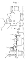
- Fig. 2 is a side view of the product supplying apparatus with a left frame and a link mechanism of an upper conveyor and a left portion of a support frame removed;
- Fig. 3 is a fragmentary enlarged plan view showing the manner in which the product is transported by the product supplying apparatus of the present invention;
- Fig. 4 is a time chart showing a comparison between a target spacing between neighboring products and an actual spacing between the neighboring products detected;
- Fig. 5 is a time chart showing an example of a control pattern for a transport drive motor;
- Fig. 6 is a table used in a spacing adjustment control; and
- Fig. 7 is a fragmentary enlarged plan view of the product supply apparatus showing an example of a specific operation of a product posture rectifying control.
-
- Hereinafter, a preferred embodiment of the present invention will be described with reference to the accompanying drawings.
- In this embodiment, the present invention is applied to such a production line as shown in Fig. 1. This production line is designed, for example, to successively manufacture bagged products X ••• X each containing a quantity of, for example, potato chips filled therein and then to package them into a box. The production line includes, in the order from an upstream side to a downstream side with respect to the direction of transport of the bagged products, a bag forming and bagging
machine 1 positioned at the preceding processing station, arelay conveyor 2, aspacing adjusting device 3, aseal checker 4, a divertingdevice 5, and abox packaging machine 6. - The bag forming and bagging
machine 1 is operable to fill the contents, the weight of which has been set to a target weight by a combination weighing machine a, into a bag and then to discharge the bagged product X onto therelay conveyor 2. This baggingmachine 1 is a bagging machine of a vertical pillow type. The baggingmachine 1 is also operable to form a horizontally extending transverse seal in upper and lower ends of the bagged product X then depending vertically (as represented respectively by hatched areas S1 and S1 in Fig. 3) and also to form a vertically extending longitudinal seal (similarly represented by a hatched area S2) extending perpendicular to any one of the transverse seals. These seals are formed by a heat fusion. - In the
bagging machine 1, the contents filled in the bagged product X nests in a lower region of the bag. As a result thereof, the lower region of the bag swells while the opposite upper region thereof is thin. When discharged onto therelay conveyor 2 while the bagged product X is in this condition, the bagged product X is laid on therelay conveyor 2 in such a posture that the lower region thereof swelling with the contents is oriented forwards while the upper region thereof then containing little contents is oriented rearwards. At this time, the longitudinal seal is oriented so as to extend in a direction conforming to the direction of transport. Also, in view of the fact that a longitudinal sealing device 1a forming a part of the baggingmachine 1 is positioned frontward, the longitudinal seal on the bagged product X laid on therelay conveyor 2 is oriented upwards in a direction away from therelay conveyor 2. Therelay conveyor 2 transports and elevates the bagged product X towards the spacing adjustingdevice 3. - The
spacing adjusting device 3 is nothing other than the product supply apparatus to which the present invention pertains. Thisdevice 3 is operable to successively receive the bagged products X ••• X that have been transported by therelay conveyor 2 and then to supply them towards theseal checker 4. Theseal checker 4 is operable to transport the bagged products X ••• X successively and at the same time to press the bagged products X ••• X one at a time with a presser plate so that the acceptability of all of the seals in each of the bagged products X ••• X can be determined in terms of the behavior of the presser plate. The divertingdevice 5 is operable to divert the bagged products X ••• X, which have been accepted as a result of the seal checking, successively into two rows of the bagged products, and thebox packaging machine 6 is operable to package the bagged products X ••• X into a cardboard box in a plurality of stages. - As shown in Fig. 2, the
spacing adjusting device 3 includes asupport framework 31 connected with a downstream end of a framework 2a of therelay conveyor 2. Thesupport framework 31 includes a plurality ofbeam members 31a ••• 31a all assembled together in three dimensions. Upper and lower transport means in the form of upper andlower conveyors servo motor 37 for driving the upper andlower conveyors sensor 38 are assembled together in thissupport framework 31. - The
lower conveyor 33 is mounted on an intermediate portion of thesupport framework 31 through acasing 32. Thislower conveyor 33 is of a structure wherein aflat belt 33c is drivingly trained around and between anupstream roller 33a and adownstream roller 33b (See Fig. 3). These tworollers belt 33c is deployed substantially horizontally. Adownstream roller 2b of therelay conveyor 2 is positioned in the vicinity of theupstream roller 33a of thelower conveyor 33 and anupstream roller 4a of theseal checker 4 is positioned in the vicinity of thedownstream roller 33b. The bagged product X are successively moved over respective gaps delimited between the adjoining rollers during the sequential transport thereof from therelay conveyor 2 to theseal checker 4 through thespacing adjusting device 3. - An
upper conveyor 35 is mounted on an upper end of thesupport framework 31 through mountingbrackets 34 ••• 34. Thisupper conveyor 35 includes left andright frames mechanisms frames frames link mechanisms flat belts rollers 35c to 35i while being positioned left and right (See Fig. 3). - Of the
link rollers upstream link roller 35h is positioned at a higher level than that of thedownstream link roller 35i. Accordingly, respective lower runs of thebelts belts lower belt 33c, specifically the space between the respective lower runs of the upper juxtaposedbelts lower belt 33, decreases progressively from an upstream side towards an downstream side with such space at the downstream side being narrower than that at the upstream side. - The
upstream roller 35h of theupper conveyor 35 is positioned at a location upstream with respect to theupstream roller 33a. Accordingly, respective upstream ends of the upper juxtaposedbelts upper belts relay conveyor 2. - The
upper conveyor 35 is provided with adamper 36. Thisdamper 36 is operable to damp vibrations of thelink mechanisms link mechanisms frame rollers relay conveyor 2 is brought into contact with that overlapping portions of the upper juxtaposedbelts - In addition, this
damper 36 has a function of pulling thelink mechanisms link mechanisms frame rollers link mechanisms damper 36, the masses of thelink mechanisms link rollers belts damper 36, the height of the lower runs of the upper juxtaposedbelts lower belts - The
drive motor 37 for driving the upper andlower conveyors casing 32. Thismotor 37 may be, for example, a servo motor and for each control cycle, the driving speed, the driving force, the driving amount and others can be changed as desired (See motor control pattern α and β in Figs. 5 and 6). Accordingly, the transport speed, the transport torque, the transport distance and others of each of the upper andlower conveyors servo motor 37, can be adjusted in various patterns. - A
timing belt 37c is trained around a pulley 37a mounted on an output shaft of thedrive motor 37, a pulley (roller pulley, not shown) coaxially mounted on one of the rollers, that is, theroller 33b (a drive roller) of theupper conveyor 35 and also on one of the rollers, that is, theroller 35f (a drive roller) of thelower conveyor 33, and atension pulley 37b accommodated within thecasing 32. Rotation of themotor 37 can be transmitted to thedrive rollers timing belt 37c. In this case, the above described roller pulleys have an equal diameter and, consequently, the upper andlower belts lower conveyors relay conveyor 2, in a downstream direction while sandwiching them therebetween. - The photo-
sensor 38 includes a light emitting element 38a and alight receiving element 38b positioned on upper and lower sides of the transport path for the bagged products X. The light emitting element 38a is mounted on, for example, the mountingbracket 34 whereas thelight receiving element 38b is mounted on thebeam member 31a. A beam of light projected from the light emitting element 38a towards thelight receiving element 38b travels through a gap between thedownstream roller 2b of therelay conveyor 2 and theupstream roller 33a of thelower conveyor 33 as shown by the broken line L. In other words, this photo-sensor 38 is operable to detect a leading end of each of the bagged products X at the location where the respective bagged product X is delivered from therelay conveyor 2 onto thelower conveyor 33, and then to detect receipt of the bagged product X by thespacing adjusting device 3. - The
interval adjusting device 3 is provided with anair nozzle 39 as a cooling means for cooling the seals in each of the bagged products X. Thisair nozzle 39 is disposed above the transport path for the bagged products X with its blowoff port oriented downwardly. This nozzle is positioned immediately above a space between the two juxtaposedupper belts lower belts upper belts air nozzle 39 blows an air towards an exposed portion thereof to thereby cool the forward and rearward transverse seals S1 and S1 of the respective bagged product X and, also, the longitudinal seal S2 thereof that extends in a direction conforming to the transport direction. - As shown in Fig. 2, the
interval adjusting device 3 has acontrol unit 40 mounted thereon. Thiscontrol unit 40 is operable to control theservo motor 37 for driving the conveyors based on a result of detection provided by the photo-sensor 38 each time the bagged products X are successively delivered. Accordingly, the interval between the neighboring bagged products X ••• X discharged randomly from the bag forming and baggingmachine 1 in the preceding processing station and subsequently transported by therelay conveyor 2, with respect to the transport direction can be adjusted to a target interval. This target interval (T. See Fig. 4) is so chosen as to be a interval of a size which would not allow theseal checker 4, located downstream, to result in inspection error and, also, which would not result in lowering of the handling capacity of the production line. The detail of the operation of this interval adjustment will be described later. - This
interval adjusting device 3 has a basic function of catching each of the bagged products X successively transported by therelay conveyor 2 by sandwiching it from above and below by means of therespective belts lower conveyors seal checker 4 by transporting the respective bagged product X in the downstream direction by the travel of thebelts servo motor 37, the transport speed and others associated with the transport of the bagged product X are variously controlled to adjust the interval between the neighboring forward and rearward bagged products X ••• X to a predetermined target interval T. Thus, thisinterval adjusting device 3 has, in the first place, a function of adjusting the interval between the neighboring products. - Also, since during the transport of the bagged products X each bagged product X is sandwiched from above and below by the upper and lower
flat belts lower belts interval adjusting device 3 has, in the second place, a function of flattening the products one at a time. - In addition, since during the transport of the bagged products X the
air nozzle 39 blows an air towards each of the bagged products X, the transverse seals S1 and S2 and the longitudinal seal S2 of each bagged product X can be cooled to thereby facilitate and complete the thermal bonding as hereinbefore described. Thus, in the third place, theinterval adjusting device 3 has a function of cooling the seals. - As discussed above, the
interval adjusting device 3 can perform respective operations to adjust the interval between the forward and rearward neighboring bagged products X, to flatten the bagged product and to cool the seals all at a time during the successive transport of the bagged products X. Consequently, there is no need to incorporate machines each dedicated to the particular operation in the production line and, therefore, it is possible to suppress elongation of the production line. -
- 1. With this
interval adjusting device 3, since the transport means 33 and 35 are disposed above and below so that each bagged product X can be sandwiched from above and below and, as a result thereof, the contents can spread in a horizontal plane, the flattening operation can be realized. Where, for example, the transport means 33 and 35 are employed left and right so that each bagged product X can be sandwiched laterally from left and right, the contents will spread in a vertical plane and, as a result thereof, some of the contents pushed upwards may fall downwards again, making it very difficult to avoid the presence of a bias of the contents within each bagged product X. - 2. Also, with this
interval adjusting device 3, since the leading end of each bagged product X previously sandwiched between the upper and lower transport means 33 and 35 swells by the effect of a bias of the contents while a trailing end of each bagged product X subsequently sandwiched has a room because of the absence of the contents, the contents can be pushed from the leading end towards the trailing end by the upper and lower transport means 33 and 35 to thereby flatten the respective bagged product X. If conversely the leading end of each bagged product X is empty while the trailing end thereof is crowded, this will not result in a favorable flattening operation. - 3. Since arrangement has been made to flatten each bagged product X
by pressing it by means of the
flat belts - 4. Since each bagged product X is firmly sandwiched and thus retained
by the
flat belts - 5. Also, since the space between the upper and
lower belts - 6. Since the upper and
lower belts single drive source 37, not only can the respective transport speeds of the upper and lower transport means 33 and 35 coincide with each other to thereby secure a interval adjusting accuracy, but also no unreasonable stress such as, for example, twisting will develop in each bagged product X to thereby avoid such inconveniences as frictional wear, damage and/or deviation in posture of the respective bagged product X and any possible cracking and/or deformation of the contents. - 7. Yet, since the upstream ends of the lower runs of the
upper belts lower belt 33c, the respective bagged product X transported by therelay conveyor 2 so as to elevate can be first brought into contact with the overlapped portion of theupper belts lower conveyors - 8. Since the respective upstream ends of the
upper belts relay conveyor 2, when being delivered, the bagged product X then in a condition being transported solely by therelay conveyor 2 is, after having been transported by therelay conveyor 2 and theupper conveyor 35 of theinterval adjusting device 3, sandwiched between and transported by the upper andlower conveyors interval adjusting device 3. Accordingly, for example, as a routine of the interval adjusting operation of theinterval adjusting device 3 the transport speeds of the upper andlower conveyors lower conveyors relay conveyor 2, a change in speed of the respective bagged product X will be so moderate that the respective bagged product X can be delivered onto and received smoothly and with no trouble by theinterval adjusting device 3. - 9. Furthermore, since the
upper conveyor 35 is so designed as to be movable up and down by means of thelink mechanisms upper conveyor 35 can be pushed upwardly by the bagged product X then received thereby. As a result thereof, for each bagged product X, the space between the upper andlower conveyors lower conveyors lower conveyors -
-
- 1. The
interval adjusting device 3 is so designed as to receive through therelay conveyor 2 each of the bagged products X, then successively discharged from the bag forming and baggingmachine 1 and then supply it to theseal checker 4 positioned downstream thereof. In this connection, in order to increase the handling capacity of the production line, the bagged products X discharged successively from the bag forming and baggingmachine 1 are supplied in a short time to theseal checker 4 one at a time. Accordingly, it is necessary to quickly complete the thermal bonding of the seals S1 and S1 and S2 in each of the bagged products X. In view of this, theair nozzle 39 is incorporated in theinterval adjusting device 3 positioned between the bag forming and baggingmachine 1 and theseal checker 4 so that each bagged product X prior to being supplied to theseal checker 4 can have its seals S1 and S1 and S2 cooled. Accordingly, the thermal bonding to form the seals S1 and S1 and S2 can be completed quickly and the possibility of the respective bagged product X being ruptured for any of the seals S1 and S1 and S2 can be advantageously minimized. - 2. In addition, the
air nozzle 39 is disposed upstream of the upper andlower conveyors lower conveyors interval adjusting device 3 can be minimized. - 3. Moreover, since the
air nozzle 39 is disposed above the transport path so that the respective bagged product X can be cooled from an upper surface where the longitudinal seal S2 is situated, the transverse seals S1 and S1 at the forward and rearward ends of the respective bagged product X and the longitudinal seal S2 thereof can be efficiently cooled simultaneously. - 4. In such case, since the longitudinal seal S2 extends in a direction
conforming to the transport direction, the longitudinal seal S2 can be exposed to
the outside through the space between the
upper belts air nozzle 39 being moved and, consequently, the longitudinal seal S2 can be effectively cooled over its entire length. -
- Fig. 4 illustrates results of comparison between target intervals T ••• T, stored in the control unit (hereinafter referred to as "ECU") 40 and take-in timing t1, t2, •••, and results of actual detection of the bagged products X ••• X by the photo-
sensor 38. If the bagged products X ••• X are successively transported at respective target intervals T ••• T from the beginning, the bagged products X ••• X traverse successively across the photo-sensor 38 at respective timings t1, t2, •••. In such case, theinterval adjusting device 3 need not perform the interval adjustment and the bagged products X ••• X can be transported at the same speed as that of therelay conveyor 2. The speed at that time is represented by a standard speed Vo and, if as shown in Fig. 5, the bagged products are successively transported at the standard speed Vo for a standard time To from the timing ts, at which the transport is initiated, to the timing τ at which the transport completes, the bagged products X can be successively transported past theinterval adjusting device 3 and then delivered onto theseal checker 4. In other words, the product of the standard transport speed Vo multiplied by the standard transport time To represents the distance of transport (fixed: Generally corresponding to the length of the upper run of thelower belt 33c) performed by theinterval adjusting device 3. - In contrast thereto, if as shown, for example, by X2 in Fig. 4, the subsequent bagged product is detected a timing (Δτ 2) earlier than the target take-in timing t2, such bagged product X2 has to be transported at a speed lower than the standard speed Vo so that at the time such bagged product X2 is delivered onto the
seal checker 4 the interval between the preceding bagged product X1 and the subsequent bagged product X2 can attain the target interval T. Conversely, if as shown by X3 the subsequent bagged product is detected a timing (Δτ 3) delayed from the target take-in timing t3, such bagged product X3 has to be transported at a speed higher than the standard velocity Vo so that at the time such bagged product X3 is delivered onto theseal checker 4 the interval between the preceding bagged product X2 and the subsequent bagged product X3 can attain the target interval T. - The
ECU 40 stores therein a table in which as shown I in Fig. 6, the length of time (Δτ) to be modified so as to increase or decrease is defined in correspondence with a control pattern performed by theservo motor 37. In the illustrated embodiment as shown in Fig. 6, the control pattern to be employed when the bagged product X is transported delayed and, hence, the length of time (Δτ) to be modified is a positive sign (+) is represented by α(n) whereas the control pattern to be employed when the bagged product X is transported earlier and, hence, the length of time (Δτ) to be modified is a negative sign (-) is represented by β (n). TheECU 40 compares the actual take-in timing, shown by a white circle in Fig. 4, with the standard take-in timing shown by a black circle in Fig. 4 to determine a deviation (Δτ = Target Value - Actual Value) therebetween and then to apply the deviation to the table to thereby determine the control pattern. - By way of example, where the bagged product X is to be transported at a speed higher than the standard speed Vo, as shown by the chain line α (n) in Fig. 5, the transport speed increases to a protruding trapezoidal shape. The area of surface of a hatched area corresponds to the transport distance by the
interval adjusting device 3. Accordingly, the transport time can be shortened by an increment of the speed and the timing τ at which the transport completes is advanced the length of time to be modified (Δτ = +a(n)) with the interval between it and the preceding bagged product X being consequently adjusted to the target value T. - Conversely, where the bagged product X is to be transported at a speed lower than the standard speed Vo, as shown by the chain line β (n) in Fig. 5, the transport speed increases to a recessing trapezoidal shape. The area of surface of a hatched area corresponds to the transport distance by the
interval adjusting device 3. Accordingly, the transport time can be prolonged by a decrement of the speed and the timing τ at which the transport completes is delayed the length of time to be modified (Δτ = -a(n)) with the interval between it and the preceding bagged product X being consequently adjusted to the target value T. - The transport speed of the
interval adjusting device 3, that is, the driving speed of theservo motor 37 may represent, other than the trapezoidal change discussed above, a sinusoidal change, a constant speed change, a cycloidal change, a modified sinusoidal change, a modified constant speed change, a trapecloidal change, a one-dwell change, or a so-called universal cam curve or the like. -
- 1. As shown in Fig. 7, each of the upper and
lower conveyors interval adjusting device 3. Accordingly, while any possible elongation of the production line is avoided, the posture of the bagged product X relative to a corrugated cardboard box can be corrected, and the subsequent processing of boxing can be performed smoothly.By way of example, in the illustrated example, by driving the right belt at a speed higher by ΔV than the target speed V (the predetermined speed for the interval adjustment) and the left belt at a speed lower by ΔV than the target speed V, the bagged product X while being transported at the target speed V can be skewed an angle leftwards to rectify the posture thereof to assume a longitudinally oriented posture. The modified speed Δv increases in proportion to the angle . - 2. The
drive roller 35f for theupper conveyor 35 has respective portions of theendless belts roller 35f is made detachable by means of a so-called snap-on latch, removal ofsuch roller 35f would result in loosening of thebelts belts device 3 and, accordingly, a cleaning job or the like can be facilitated. - 3. Since it is sufficient for the
damper 36 to pull upwardly only portions of thelink mechanisms other frame rollers 35c to 35g of theupper conveyor 35 is loaded thereon, thedamper 36 may have a compact size. It is, however, to be noted that while the damper is employed solely to absorb the vibrations of thelink mechanisms link mechanisms - 4. The manner of cooling the seals S1 and S1 and S2 may be not be limited to the coolant blow, but may be accomplished by sandwiching the bagged product X by means of transport belts then cooled to a low temperature. In such case, the upper belt may not be divided into two, but a single belt may be employed therefore. Also, the bagged product X is cooled while the bagged product X including the seals S1, S1 and S2 is totally sandwiched and pressed by such belt and is transported in this manner. Also, even in the case of the coolant blow, the upper belt may not be divided into two, but may be a single belt. It is, however, that in such case, the belt in the form of a mesh belt should be employed so that the bagged product X can be exposed to the outside. In addition, when the belt is to be divided, the number of division may not be limited to two, but three or more so that a portion of the bagged product X to be cooled can be exposed to the outside.
- 5. It is sufficient for the
air nozzle 39 to be disposed on one side adjacent to the longitudinal seal S2 and may not therefore be limited to the position above the bagged product X, but may be disposed at a position below the transport path depending on the position of the longitudinal seal S2 being transported. - 6. Since the bagged product X is pressed by the upper and
lower belts upper belts air nozzle 39 can favorably impinge upon the seals S1, S1 and S2 to facilitate the cooling operation efficiently. - 7. Since as a result of the flattening operation, the upper surface of the bagged product X is held flat, when the bagged product X is to be sucked and captured from above during the subsequent processing such as a diverting operation and/or a packaging operation or the like, such suction can be performed effectively and the bagged product X can be successfully captured.
- 8. The
quality inspecting machine 4 may not be always limited to the seal checker, but may be, for example, a weight checker, an X-ray inspecting machine, a metal detector or the like and one or a combination of them may be employed and arranged, for example, in a series with respect to each other. - 9. Where the target interval T varies depending on the
quality inspecting machine 4, if theinterval adjusting device 3 is made to receive the target interval T from thequality inspecting machine 4, the target value T may not be re-set on the side of theinterval adjusting device 3 each time thequality inspecting machine 4 is changed. Similarly, where the target interval T varies depending on the type of the bagged products X, if theinterval adjusting device 3 is made to receive the target interval T from an upstream product manufacturing apparatus (in the illustrated embodiment, for example, the bag forming and bagging machine 1) or the like, the target value T need not be re-set on the side of theinterval adjusting device 3 each time the product manufacturing apparatus is changed or the type of the bagged products X are changed even though the product manufacturing apparatus remains the same. -
- Although the present invention has been fully described in connection with the preferred embodiments thereof with reference to the accompanying drawings which are used only for the purpose of illustration, those skilled in the art will readily conceive numerous changes and modifications within the framework of obviousness upon the reading of the specification herein presented of the present invention. Accordingly, such changes and modifications are, unless they depart from the scope of the present invention as delivered from the claims annexed hereto, to be construed as included therein.
Claims (8)
- A product supply apparatus for successively receiving products, transported from a previous processing station, and then supplying them towards a quality inspecting machine positioned downstream thereof, which apparatus comprises upper and lower transport means for transporting the products successively while sandwiching the products from above and below; a detecting means for detecting each of the products; and an interval adjusting means for controlling the transport means based on a result of detection by the detecting means each time the product is received and for adjusting an interval between the forward and rearward neighboring products to a target interval.
- The product supply apparatus as claimed in Claim 1, wherein a space between the upper and lower transport means gradually varies to a narrow space at a downstream side.
- The product supply apparatus as claimed in Claim 1, wherein the upper and lower transport means are adapted to be driven by a single drive source.
- The product supply apparatus as claimed in Claim 1, wherein an upstream end of the upper transport means is disposed at a location upstream of an upstream end of the lower transport means.
- The product supply apparatus as claimed in Claim 1, wherein the upper transport means is movable up and down.
- The product supply apparatus as claimed in Claim 1, further comprising a cooling means for cooling a sealed portion of each of the products which have been bagged.
- The product supply apparatus as claimed in Claim 6, wherein the cooling means is operable to cool each of the bagged products from a side where a longitudinal seal is formed.
- The product supply apparatus as claimed in Claim 1, wherein the transport means is provided with a posture modifying means for sandwiching each of the products at a plurality of locations and for controlling a transport speed at each of those locations to thereby correct a posture of each of the product.
Applications Claiming Priority (3)
| Application Number | Priority Date | Filing Date | Title |
|---|---|---|---|
| JP2001039591 | 2001-02-16 | ||
| JP2001039591A JP4948711B2 (en) | 2001-02-16 | 2001-02-16 | Article supply equipment |
| PCT/JP2001/011222 WO2002064465A1 (en) | 2001-02-16 | 2001-12-20 | Article feeding device |
Publications (3)
| Publication Number | Publication Date |
|---|---|
| EP1369362A1 true EP1369362A1 (en) | 2003-12-10 |
| EP1369362A4 EP1369362A4 (en) | 2006-12-06 |
| EP1369362B1 EP1369362B1 (en) | 2009-09-02 |
Family
ID=18902344
Family Applications (1)
| Application Number | Title | Priority Date | Filing Date |
|---|---|---|---|
| EP01273381A Expired - Lifetime EP1369362B1 (en) | 2001-02-16 | 2001-12-20 | Article feeding device |
Country Status (5)
| Country | Link |
|---|---|
| US (2) | US20030019728A1 (en) |
| EP (1) | EP1369362B1 (en) |
| JP (1) | JP4948711B2 (en) |
| DE (1) | DE60139812D1 (en) |
| WO (1) | WO2002064465A1 (en) |
Cited By (3)
| Publication number | Priority date | Publication date | Assignee | Title |
|---|---|---|---|---|
| EP1793216A3 (en) * | 2005-11-30 | 2008-05-07 | Ishida Co., Ltd. | Package seal checker |
| FR3044647A1 (en) * | 2015-12-03 | 2017-06-09 | Kaufler | DEVICE FOR TRANSPORTING AT LEAST ONE FOOD PREPARATION |
| CN113562401A (en) * | 2021-07-23 | 2021-10-29 | 杭州海康机器人技术有限公司 | Control target object transmission method, device, system, terminal and storage medium |
Families Citing this family (8)
| Publication number | Priority date | Publication date | Assignee | Title |
|---|---|---|---|---|
| WO2008082580A1 (en) * | 2006-12-29 | 2008-07-10 | Cargill, Incorporated | Apparatus and method for the enhancement of contaminant detection |
| DE102007029278A1 (en) * | 2007-06-22 | 2008-12-24 | Haver & Boecker Ohg | Packing machine and discharge device for a packing machine |
| WO2014067559A1 (en) * | 2012-10-30 | 2014-05-08 | Loesch Verpackungstechnik Gmbh | Method and device for producing strip-shaped objects, in particular sticks of chewing gum |
| HUP1300269A2 (en) * | 2013-03-01 | 2014-09-29 | Attila Rakosi | Horizontal packet-maker device with metal detektor and removal |
| DE102013208561A1 (en) * | 2013-05-08 | 2014-11-13 | Gebr. Willach Gmbh | manipulator |
| CN109250165A (en) * | 2018-08-28 | 2019-01-22 | 安徽凯德橡塑有限公司 | A kind of sealing element packing machine device |
| CN110844137B (en) * | 2019-10-09 | 2022-06-17 | 兖矿集团有限公司 | Online rechecking joint control weighing and filling system and method for correcting weighing error thereof |
| CN114180294B (en) * | 2022-02-16 | 2022-06-14 | 江苏智仁景行新材料研究院有限公司 | High-precision feeding control system based on switching decision |
Citations (4)
| Publication number | Priority date | Publication date | Assignee | Title |
|---|---|---|---|---|
| JPS5420567A (en) * | 1977-07-14 | 1979-02-16 | Tokiwa Kogyo Kk | Automatic feeder |
| EP0535543A2 (en) * | 1991-09-30 | 1993-04-07 | Hitachi, Ltd. | Paper sheet conveying device and automatic cash handling apparatus |
| EP0556497A1 (en) * | 1992-02-19 | 1993-08-25 | Longford Equipment International Limited | Apparatus for feeding packages from a web of packages to a receptacle |
| EP1086897A2 (en) * | 1999-09-27 | 2001-03-28 | Ishida Co., Ltd. | Seal inspecting machine for bagged products |
Family Cites Families (33)
| Publication number | Priority date | Publication date | Assignee | Title |
|---|---|---|---|---|
| US1807312A (en) * | 1927-01-10 | 1931-05-26 | Jr William J Henley | Continuous reversible toaster |
| US2577765A (en) * | 1948-06-26 | 1951-12-11 | Nat Urn Bag Co Inc | Packaging beverage infusor units having string handles and tags |
| US3581876A (en) * | 1969-07-07 | 1971-06-01 | Milroy A Keith | Bag flattening conveyors |
| US3645198A (en) * | 1970-03-24 | 1972-02-29 | Holland Rantos Co Inc | Method for forming liquid saturated towelette packets |
| US3717973A (en) * | 1971-01-08 | 1973-02-27 | Certain Teed St Gobain | Packaging compressible material |
| JPS4894261U (en) * | 1972-02-12 | 1973-11-10 | ||
| DE2234631A1 (en) * | 1972-07-14 | 1974-01-31 | Kabel Metallwerke Ghh | EXHAUST DEVICE FOR PRESSURE SENSITIVE GOODS |
| US3869038A (en) * | 1973-08-09 | 1975-03-04 | Stearns Mfg Co | Article conveying apparatus |
| NO140126C (en) * | 1975-05-28 | 1979-07-18 | Niemeyer Bv | APPARATUS FOR ORIENTATION OF TOBACCO LEAVES |
| AT340826B (en) * | 1975-12-12 | 1978-01-10 | Gao Ges Automation Org | TRANSPORT SYSTEM FOR FLAT TRANSPORTED GOODS, SUCH AS MONEY BILLS, DOCUMENTS, ETC. |
| US4260447A (en) * | 1979-04-20 | 1981-04-07 | Save-O-Seal | Continuous bag sealing machine |
| US4558859A (en) * | 1984-03-15 | 1985-12-17 | Harris Graphics Corporation | Stack top control method and apparatus |
| NL8402700A (en) * | 1984-04-27 | 1985-11-18 | Thomassen & Drijver | DEVICE FOR CHANGING THE DISTANCE BETWEEN OBJECTS SUPPLIED BY A CONVEYOR BELT. |
| DE8709053U1 (en) * | 1987-07-01 | 1987-09-10 | Fripack AG, Baar | Device for grouping packages |
| US5199550A (en) * | 1989-12-12 | 1993-04-06 | Nippon Kayaku Kabushiki Kaisha | Belt type transfer apparatus and sectional roller used therein |
| DE3940960A1 (en) * | 1989-12-12 | 1991-07-11 | Jagenberg Ag | METHOD AND DEVICE FOR BRAKING DOWN SHEETS TO BE PUT ON A PACK, IN PARTICULAR PAPER OR CARDBOARD SHEETS |
| US5088590A (en) * | 1990-03-30 | 1992-02-18 | Marquip, Inc. | System for changing the speed of conveyed sheets while holding register |
| US5456148A (en) * | 1990-11-09 | 1995-10-10 | Eubanks Engineering Company | Wire and cable drive apparatus in wire and cable cutting and stripping system |
| US5074402A (en) * | 1990-12-24 | 1991-12-24 | General Electric Company | Extensible ammunition conveyor |
| IT1245996B (en) * | 1991-05-24 | 1994-11-07 | Wrapmatic Spa | METHOD FOR THE WRAPPING OF STACKS OF PAPER AND EQUIPMENT THAT REALIZES IT. |
| US5195300A (en) * | 1992-03-17 | 1993-03-23 | Hayssen Manufacturing Company | Compressed roll packaging method and apparatus |
| US5930983A (en) * | 1992-06-29 | 1999-08-03 | Pacmac, Inc. | Form, fill and seal packaging machine with bag squeezer and method |
| JPH0767941B2 (en) * | 1992-07-14 | 1995-07-26 | 東洋水産株式会社 | Method and apparatus for bending top seal portion of instant noodle package |
| US5230475A (en) * | 1992-12-10 | 1993-07-27 | Banner Welder Incorporated | Conveyor system for shredder |
| US5803450A (en) * | 1993-11-02 | 1998-09-08 | Koenig & Bauer-Albert Aktiengesellschaft | Device for conveying flat floppy products |
| JP2563759B2 (en) * | 1994-07-06 | 1996-12-18 | 松下電器産業株式会社 | Sheet member feeder |
| DE69718296T2 (en) * | 1996-02-29 | 2003-09-04 | Asahi Glass Co., Ltd. | METHOD FOR PRODUCING FLAT GLASS |
| IL118123A0 (en) * | 1996-05-02 | 1996-09-12 | Farkas Shmuel | Conveyor propulsion system |
| US5884749A (en) * | 1996-09-09 | 1999-03-23 | Prototype Equipment Corporation | Conveyor system that receives articles at a constant rate and batch discharges |
| US6129204A (en) * | 1998-06-23 | 2000-10-10 | Elopak Systems Ag | Machine for asynchronously operating dual indexing conveyors |
| EP1016856B1 (en) * | 1998-12-28 | 2006-08-30 | Ishida Co., Ltd. | Combinatorial weighing system |
| US6405850B1 (en) * | 1999-03-31 | 2002-06-18 | Heidelberger Druckmaschinen Ag | Apparatus and method for advancing signatures using a retracting drive |
| AU766223B2 (en) * | 1999-09-16 | 2003-10-09 | Ferag Ag | Method and device for feeding flat items to individualization |
-
2001
- 2001-02-16 JP JP2001039591A patent/JP4948711B2/en not_active Expired - Fee Related
- 2001-12-20 US US10/130,488 patent/US20030019728A1/en not_active Abandoned
- 2001-12-20 WO PCT/JP2001/011222 patent/WO2002064465A1/en active Application Filing
- 2001-12-20 DE DE60139812T patent/DE60139812D1/en not_active Expired - Lifetime
- 2001-12-20 EP EP01273381A patent/EP1369362B1/en not_active Expired - Lifetime
-
2006
- 2006-03-20 US US11/384,886 patent/US20060157321A1/en not_active Abandoned
Patent Citations (4)
| Publication number | Priority date | Publication date | Assignee | Title |
|---|---|---|---|---|
| JPS5420567A (en) * | 1977-07-14 | 1979-02-16 | Tokiwa Kogyo Kk | Automatic feeder |
| EP0535543A2 (en) * | 1991-09-30 | 1993-04-07 | Hitachi, Ltd. | Paper sheet conveying device and automatic cash handling apparatus |
| EP0556497A1 (en) * | 1992-02-19 | 1993-08-25 | Longford Equipment International Limited | Apparatus for feeding packages from a web of packages to a receptacle |
| EP1086897A2 (en) * | 1999-09-27 | 2001-03-28 | Ishida Co., Ltd. | Seal inspecting machine for bagged products |
Non-Patent Citations (1)
| Title |
|---|
| See also references of WO02064465A1 * |
Cited By (4)
| Publication number | Priority date | Publication date | Assignee | Title |
|---|---|---|---|---|
| EP1793216A3 (en) * | 2005-11-30 | 2008-05-07 | Ishida Co., Ltd. | Package seal checker |
| US7475590B2 (en) | 2005-11-30 | 2009-01-13 | Ishida Co., Ltd. | Seal checker |
| FR3044647A1 (en) * | 2015-12-03 | 2017-06-09 | Kaufler | DEVICE FOR TRANSPORTING AT LEAST ONE FOOD PREPARATION |
| CN113562401A (en) * | 2021-07-23 | 2021-10-29 | 杭州海康机器人技术有限公司 | Control target object transmission method, device, system, terminal and storage medium |
Also Published As
| Publication number | Publication date |
|---|---|
| EP1369362A4 (en) | 2006-12-06 |
| US20030019728A1 (en) | 2003-01-30 |
| JP2002240931A (en) | 2002-08-28 |
| WO2002064465A1 (en) | 2002-08-22 |
| JP4948711B2 (en) | 2012-06-06 |
| EP1369362B1 (en) | 2009-09-02 |
| US20060157321A1 (en) | 2006-07-20 |
| DE60139812D1 (en) | 2009-10-15 |
Similar Documents
| Publication | Publication Date | Title |
|---|---|---|
| US20060157321A1 (en) | Product supply apparatus | |
| US5284003A (en) | Machine for conditioning product in a sealed bag | |
| US6474141B1 (en) | Seal inspecting machine | |
| JPH09301310A (en) | Boxing device | |
| EP1600763A2 (en) | Defect detection device and bag packaging system equipped with defect detection device | |
| US8137252B2 (en) | Packaging bag supply device and bagging device having the same | |
| US5507134A (en) | Package rectifying apparatus | |
| JP5126927B2 (en) | Horizontal pillow packaging machine | |
| JP2004262482A (en) | Commodity inspecting device, strip tape attaching system equipped with the same, and box packing system | |
| JP2002265039A (en) | Distributor and boxing system having the distributor | |
| JP2000142625A (en) | Automatic egg-sorting and packaging apparatus | |
| JP4249889B2 (en) | Seal check device | |
| JP2008013227A (en) | Transfer device and boxing apparatus equipped with the same | |
| US6581757B2 (en) | Product diverting mechanism in packaging system | |
| JP4740085B2 (en) | Supply device for bagging meat parts | |
| JPH0776322A (en) | Method to pack bag-packaged article in corrugated fiberboard box under partially overlapped condition | |
| JPH0348143A (en) | Inspecting apparatus for tablet package | |
| JPH09301305A (en) | Boxing device | |
| JP2000128124A (en) | Automatic egg classifying and packaging apparatus | |
| JP3974484B2 (en) | Article conveying apparatus and article packing apparatus provided with the same | |
| JPH09272626A (en) | Automatic feeding and arranging device for packed bag to empty tray | |
| JP2564261Y2 (en) | Package supply device | |
| JPS6322321A (en) | Method and device for pack-filling and boxing fruit | |
| JP2002166911A (en) | Bundle packaging apparatus and dummy bundle applied to the apparatus | |
| JP2023161255A (en) | Thickness measurement device for packaging bag |
Legal Events
| Date | Code | Title | Description |
|---|---|---|---|
| PUAI | Public reference made under article 153(3) epc to a published international application that has entered the european phase |
Free format text: ORIGINAL CODE: 0009012 |
|
| 17P | Request for examination filed |
Effective date: 20020531 |
|
| AK | Designated contracting states |
Kind code of ref document: A1 Designated state(s): AT BE CH CY DE DK ES FI FR GB GR IE IT LI LU MC NL PT SE TR |
|
| RIC1 | Information provided on ipc code assigned before grant |
Ipc: B65B 57/00 20060101ALN20060808BHEP Ipc: B65G 15/16 20060101ALI20060808BHEP Ipc: B65G 47/28 20060101AFI20020826BHEP Ipc: B65B 63/02 20060101ALI20060808BHEP Ipc: B65B 61/24 20060101ALI20060808BHEP Ipc: B65G 47/31 20060101ALI20060808BHEP Ipc: B65B 35/24 20060101ALI20060808BHEP Ipc: B65B 35/56 20060101ALI20060808BHEP Ipc: B65G 47/08 20060101ALI20060808BHEP Ipc: B65B 51/32 20060101ALI20060808BHEP Ipc: B65B 1/46 20060101ALN20060808BHEP |
|
| A4 | Supplementary search report drawn up and despatched |
Effective date: 20061103 |
|
| 17Q | First examination report despatched |
Effective date: 20070806 |
|
| GRAP | Despatch of communication of intention to grant a patent |
Free format text: ORIGINAL CODE: EPIDOSNIGR1 |
|
| GRAS | Grant fee paid |
Free format text: ORIGINAL CODE: EPIDOSNIGR3 |
|
| GRAA | (expected) grant |
Free format text: ORIGINAL CODE: 0009210 |
|
| AK | Designated contracting states |
Kind code of ref document: B1 Designated state(s): DE FR GB IT |
|
| REF | Corresponds to: |
Ref document number: 60139812 Country of ref document: DE Date of ref document: 20091015 Kind code of ref document: P |
|
| PLBE | No opposition filed within time limit |
Free format text: ORIGINAL CODE: 0009261 |
|
| STAA | Information on the status of an ep patent application or granted ep patent |
Free format text: STATUS: NO OPPOSITION FILED WITHIN TIME LIMIT |
|
| 26N | No opposition filed |
Effective date: 20100603 |
|
| REG | Reference to a national code |
Ref country code: FR Ref legal event code: ST Effective date: 20100831 |
|
| PG25 | Lapsed in a contracting state [announced via postgrant information from national office to epo] |
Ref country code: FR Free format text: LAPSE BECAUSE OF NON-PAYMENT OF DUE FEES Effective date: 20091231 |
|
| PGFP | Annual fee paid to national office [announced via postgrant information from national office to epo] |
Ref country code: GB Payment date: 20121220 Year of fee payment: 12 Ref country code: IT Payment date: 20121221 Year of fee payment: 12 |
|
| PGFP | Annual fee paid to national office [announced via postgrant information from national office to epo] |
Ref country code: DE Payment date: 20121220 Year of fee payment: 12 |
|
| REG | Reference to a national code |
Ref country code: DE Ref legal event code: R119 Ref document number: 60139812 Country of ref document: DE |
|
| GBPC | Gb: european patent ceased through non-payment of renewal fee |
Effective date: 20131220 |
|
| REG | Reference to a national code |
Ref country code: DE Ref legal event code: R119 Ref document number: 60139812 Country of ref document: DE Effective date: 20140701 |
|
| PG25 | Lapsed in a contracting state [announced via postgrant information from national office to epo] |
Ref country code: DE Free format text: LAPSE BECAUSE OF NON-PAYMENT OF DUE FEES Effective date: 20140701 |
|
| PG25 | Lapsed in a contracting state [announced via postgrant information from national office to epo] |
Ref country code: GB Free format text: LAPSE BECAUSE OF NON-PAYMENT OF DUE FEES Effective date: 20131220 |
|
| PG25 | Lapsed in a contracting state [announced via postgrant information from national office to epo] |
Ref country code: IT Free format text: LAPSE BECAUSE OF NON-PAYMENT OF DUE FEES Effective date: 20131231 |
|
| PG25 | Lapsed in a contracting state [announced via postgrant information from national office to epo] |
Ref country code: IT Free format text: LAPSE BECAUSE OF NON-PAYMENT OF DUE FEES Effective date: 20131220 |