EP1369199B1 - Brake pad grinding apparatus and method - Google Patents
Brake pad grinding apparatus and method Download PDFInfo
- Publication number
- EP1369199B1 EP1369199B1 EP03012111A EP03012111A EP1369199B1 EP 1369199 B1 EP1369199 B1 EP 1369199B1 EP 03012111 A EP03012111 A EP 03012111A EP 03012111 A EP03012111 A EP 03012111A EP 1369199 B1 EP1369199 B1 EP 1369199B1
- Authority
- EP
- European Patent Office
- Prior art keywords
- brake pad
- grinding
- rotation axis
- face
- rotary whetstone
- Prior art date
- Legal status (The legal status is an assumption and is not a legal conclusion. Google has not performed a legal analysis and makes no representation as to the accuracy of the status listed.)
- Expired - Fee Related
Links
Images


Classifications
-
- B—PERFORMING OPERATIONS; TRANSPORTING
- B24—GRINDING; POLISHING
- B24B—MACHINES, DEVICES, OR PROCESSES FOR GRINDING OR POLISHING; DRESSING OR CONDITIONING OF ABRADING SURFACES; FEEDING OF GRINDING, POLISHING, OR LAPPING AGENTS
- B24B19/00—Single-purpose machines or devices for particular grinding operations not covered by any other main group
- B24B19/26—Single-purpose machines or devices for particular grinding operations not covered by any other main group for grinding workpieces with arcuate surfaces, e.g. parts of car bodies, bumpers or magnetic recording heads
- B24B19/28—Single-purpose machines or devices for particular grinding operations not covered by any other main group for grinding workpieces with arcuate surfaces, e.g. parts of car bodies, bumpers or magnetic recording heads for grinding shoes or linings of drum brakes
-
- B—PERFORMING OPERATIONS; TRANSPORTING
- B24—GRINDING; POLISHING
- B24B—MACHINES, DEVICES, OR PROCESSES FOR GRINDING OR POLISHING; DRESSING OR CONDITIONING OF ABRADING SURFACES; FEEDING OF GRINDING, POLISHING, OR LAPPING AGENTS
- B24B9/00—Machines or devices designed for grinding edges or bevels on work or for removing burrs; Accessories therefor
- B24B9/002—Machines or devices designed for grinding edges or bevels on work or for removing burrs; Accessories therefor for travelling workpieces
-
- F—MECHANICAL ENGINEERING; LIGHTING; HEATING; WEAPONS; BLASTING
- F16—ENGINEERING ELEMENTS AND UNITS; GENERAL MEASURES FOR PRODUCING AND MAINTAINING EFFECTIVE FUNCTIONING OF MACHINES OR INSTALLATIONS; THERMAL INSULATION IN GENERAL
- F16D—COUPLINGS FOR TRANSMITTING ROTATION; CLUTCHES; BRAKES
- F16D65/00—Parts or details
- F16D65/02—Braking members; Mounting thereof
- F16D65/04—Bands, shoes or pads; Pivots or supporting members therefor
- F16D65/092—Bands, shoes or pads; Pivots or supporting members therefor for axially-engaging brakes, e.g. disc brakes
-
- F—MECHANICAL ENGINEERING; LIGHTING; HEATING; WEAPONS; BLASTING
- F16—ENGINEERING ELEMENTS AND UNITS; GENERAL MEASURES FOR PRODUCING AND MAINTAINING EFFECTIVE FUNCTIONING OF MACHINES OR INSTALLATIONS; THERMAL INSULATION IN GENERAL
- F16D—COUPLINGS FOR TRANSMITTING ROTATION; CLUTCHES; BRAKES
- F16D69/00—Friction linings; Attachment thereof; Selection of coacting friction substances or surfaces
- F16D2069/004—Profiled friction surfaces, e.g. grooves, dimples
Definitions
- the invention refers to an apparatus for grinding a brake pad according to the preamble of claim 1 and a method of grinding a brake pad according to the preamble of claim 5, as already disclosed in US 5,613,898.
- a brake pad set used for a disk brake of an automobile generally comprises a steel backing plate and a brake pad (friction lining layer) adhered to the backing plate. Pressing and heating powder material in which a fiber, a filler, and a binder are mixed form the brake pad.
- the disk brake reduces the speed of an automobile by pressing the brake bad to a steel rotor disk.
- the disk pad set and the rotor disk may vibrate to generate squealing.
- This squealing becomes an unpleasant noise, so that a variety of measures have been taken so far.
- an inclined face can be formed on each of the both ends of a brake pad as a known measure.
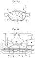
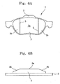
- Figure 6 shows a conventional brake pad set with inclined faces, in which A is a front view, and B is a bottom view.
- the brake pad set 1 shown in Fig. 6 comprises a steel backing plate 2 and a brake pad 3 adhered thereto.
- the brake pad 3 comprises a central flat friction face 3a and inclined faces 3b, 3b at both ends. Boundary lines 5, 5 between the friction face 3a and the inclined faces 3b, 3b are parallel with each other. This construction allows the lengths of the friction faces 3a contacting a rotor disk on the outer side and inner side become equal.
- the provision of the inclined faces 3b, 3b allows the area of the friction face 3a to be reduced, resulting in reduced squealing.
- Figure 7 shows another conventional brake pad set with inclined faces.
- Figure 7A shows a brake pad set in which inclined faces 3d, 3d are formed at both ends in such a manner that a friction face 3c becomes a part of a sector of which longer circumference is positioned on the outer side of a rotor disk
- Fig. 7B shows another brake pad set in which inclined faces 3f, 3f are formed such that a friction face 3e becomes a part of a sector of which longer circumference is positioned on the inner side of a rotor disk.
- Boundary lines 6, 6 shown in Fig. 7A and boundary lines 7, 7 in Fig. 7B are not parallel with each other. In other words, in the brake pad set 1 illustrated in Fig.
- the length of the friction face 3c contacting a rotor disk on the outer side thereof is longer than that of the friction face 3c contacting a rotor disk on the inner side thereof.
- the length of the friction face 3e contacting a rotor disk on the outer side thereof is shorter than that of the friction face 3e contacting a rotor disk on the inner side thereof.
- the brake pad set 1 comprises the steel backing plate 2 and a brake pad attached thereto. After adhered to the backing plate 2, the brake pad is ground to finish the friction face 3a, 3c, 3e to a flat face with a desired flatness and to form the inclined faces 3b, 3d, 3f.
- the above grindings are performed with rotary whetstones 4, and a process of grinding the friction faces 3a, 3c, 3e and a process of grinding the inclined faces 3b, 3d, 3f are separately performed.
- plurality of whetstones with different angles corresponding to the angles of the inclined faces to be ground are prepared for grinding the inclined faces 3b, 3d, 3f, and after the inclined face 3b, 3d, 3f are formed by using a predetermined tool, the friction faces 3a, 3c, 3f are ground to be flat.
- the grindings of both ends of the inclined faces 3b, 3d, 3f are not carried out simultaneously, but are ground from one side to the other, one by one.
- the brake pad set 1 is supported as shown in Fig. 8A.
- the rotary whetstone 4 is positioned such that a rotation shaft 4a becomes parallel to the friction face 3a. Under the condition, the rotary whetstone 4 is rotated in a direction shown by the arrow D, and grinding starts from the right end of the brake pad 3 through the rotary whetstone 4.
- the brake pad set 1 moves right in the Figure, and this direction coincides with a circumference of a rotor disk not shown.
- grinding starts from a condition that the brake pad set 1 is situated near the rotary whetstone 4, and the brake pad set 1 moves in such a manner as to become far from the rotary whetstone 4 as the brake pad set 1 moves rightward, which allows an end of the inclined face 3b to be formed as illustrated in Fig. 8B.
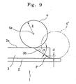
- Figure 9 shows an enlarged view of the brake pad set 1 and the rotary whetstone 4 illustrated in Fig. 4.
- the rotary whetstone 4 moves from the position shown by the solid line along the inclined face 3b. Since the brake pad 3 is adhered to the backing plate 2, when the backing plate 2 considerably projects out of the brake pad 3, after reaching to the position shown by the phantom line, the rotary whetstone 4' can not move along the inclined face 3b any more. Therefore, the inclined face 3b is only formed up to a contact point P of the rotary whetstone 4' and inclined face 3b, so that a portion d remains as it is.
- the present invention has been made to solve the above problems and it is an object of the present invention to provide a method of and an apparatus for grinding a brake pad in which inclined faces at both ends of the brake pad can be ground along a single route and no grinding limit quantity is generated whether the boundary lines are parallel with each other or not.
- an apparatus for grinding a brake pad according to the present invention is characterized in by features of claim 1.
- the rotary whetstone of the apparatus for grinding a brake pad is be provided with a cylindrical portion between the grinding faces, and distance between a grinding face of the cylindrical portion and the rotation axis is constant. It is also possible to construct the fixing portion so as to change an angle that the brake pad is supported, and to construct the rotary whetstone so as to change a distance to the brake pad.
- a method of grinding a brake pad according to the present invention is characterized by features of claim 5.
- the grinding can be performed from an end to the other end of the brake pad, and at the relative movement between the brake pad set and the rotary whetstone, distance between the brake pad set and the rotary whetstone is gradually changed, or the rotary whetstone may be provided with a cylindrical portion between the grinding faces; distance between a grinding face of the cylindrical portion and the rotation axis is constant; inclined faces are formed at both ends of the brake pad by the two grinding faces of which distance to the rotation axis increases gradually or in plurality of steps; and a friction face is formed between the both inclined faces by the cylindrical portion.
- FIG. 1 shows the first embodiment of the present invention, in which A is a plan view of a brake pad set, which is the same drawing as Fig. 6A.
- Figure 1B shows a condition that both ends of a brake pad are being ground.
- the brake pad set 1 is fixed on a transporter 10 through an electromagnet 11 as a fixing section.
- the transporter 10 is a conveyor in this embodiment.
- the electromagnet 11 circulates together with the conveyor, and when the electromagnet 11 reaches a grinding position, it is powered and works as a magnet to attract and fix a steel backing plate 2 of the brake pad set 1.
- the electromagnet 11 leaves the grinding position, the charge to the electromagnet 11 stops, so that the brake pad set 1 is released and becomes detachable from the conveyor.
- the brake pad set 1 can be fixed by a mechanical cramping means other than the electromagnet 11.
- the transporter 10 is not limited to the conveyor, but a bed of a grinding apparatus 20 and a feed screw can transport the brake pad set 1. On the contrary, it is possible to move the whetstone instead of the brake pad set 1.
- the grinding apparatus 20 is provided with a rotary whetstone 21.
- Combining grinding particles such as diamond forms the rotary whetstone 21.
- the rotary whetstone 21 comprises two rotary whetstone portions 21a, 21b, of which diameter gradually increases toward outer portions thereof, and a shaft 22 connecting the two rotary whetstone portions 21a, 21b. That is, the distance between a rotation axis a to the grinding face of the whetstone portion 21a lineally increases toward the right-hand of the rotation axis a. On the other hand, the distance between a rotation axis a to the grinding face of the whetstone portion 21a lineally decreases toward the right-hand of the rotation axis a.
- the whetstone portions 21a, 21b can be connected with each other at opposing portions thereof to form a single hand-drum-shaped whetstone.
- the shaft 22 of the rotary whetstone 21 rotates by a motor 23 mounted to the grinding apparatus 20.
- a motor 23 mounted to the grinding apparatus 20.
- the inclined faces 3b, 3b at the both ends can be formed through one grinding motion.
- the inclined faces 3b, 3b which are formed as described above, are provided with parallel boundary lines 5, 5 shown in Fig. 1A.
- the friction face 3a is ground in advance, or the face 3a is ground after the grindings of the inclined faces 3b, 3b.
- the rotation axis a of the rotary whetstone 21 is set parallel to the friction face 3a, and the rotation axis a is arranged in such a manner as to extend from one inclined face 3b to the other inclined face 3b of the brake pad set 1, so that the grinding limit quantity shown in Fig. 9 can be eliminated.
- Fixing the brake pad set 1 while slightly rotating on the surface of the transporter 10 can incline the boundary lines 5, 5 as shown by the lines 5', 5" in Fig. 1A.
- the rotary whetstone 21 is formed to be a truncated cone, which allows the inclined face 3b to have flat surface.
- the inclined face 3b is not limited to have such a flat surface.
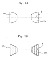
- FIG. 2 shows other rotary whetstones according to the present invention.
- Rotary whetstones 21c, 21c shown in Fig. 2A have cross-sections with outwardly bulged circumference of an oval.
- an arc of a circle, a parabola, a hyperbola and so on may be adopted, and they may be inwardly bulged.
- Figure 2B shows an example of tiered rotary whetstones 21d, 21d.
- rotary whetstones according to the present invention may have grinding faces that the distances between portions on the grinding faces and the rotation axis a smoothly or stepwise increase or decrease along the rotation axis a toward one end thereof.
- Figure 3 shows the second embodiment of the present invention.
- the rotary whetstone 30 is provided with truncated cone portions 31, 31 at both ends thereof, and between the truncated cone portions 31, 31, a cylindrical portion 32 of which grinding face is equally apart from the rotation axis a.
- the truncated cone portions 31, 31 form the inclined faces 3b, 3b at both ends, and the cylindrical portion 32 in the middle grinds the friction face 3a.
- Figure 4 is a schematic view for explaining an apparatus and method according to the third embodiment of the present invention.
- the inclined lines 3d, 3 f of which boundary lines 6, 6 in the Fig. 7A or the boundary lines 7, 7 in the Fig. 7B are not parallel with each other, can be ground along a single route.
- the transporter 10 is provided with a concaved fixing portion 10a to fix the brake pad set 1 in such a manner as to be inclined at an angle ⁇ .
- the transporter 10 is formed on the conveyor.
- a projecting fixing portion 10b is formed on the transporter 10 to fix the brake pad set 1 so as to be inclined at an angle ⁇ .
- the angle ⁇ is exaggerated, and the angle ⁇ is actually between approximately 3 to 30 degrees and preferably between approximately 5 to 15 degrees.
- the brake pad set 1 is fixed so as to be inclined at the angle ⁇ , and is ground with the same rotary whetstone 21 as shown in Fig. 1.
- the inclined faces 3d, 3d at both ends of the brake pad set 1 are ground along a single route.
- the inclined faces 3f, 3f shown in Fig. 7B can be ground along a single route.
- the fixing portions 10a, 10b always fix the brake pad set 1 so as to be inclined at the angle ⁇
- FIG. 5 is a schematic view for explaining the third embodiment of the present invention.
- the brake pad set 1 is maintained flat on the fixing portion and the route of a transporter is inclined.
- the brake pad set 1 is ground while a transporter 10' lifts the brake pad set 1 from the lower-right to the upper-left of the rotary whetstone 21.
- the brake pad set 1 is ground while a transporter 10" lowers the brake pad set 1 from the upper-right to the lower-left of the rotary whetstone 21.
- the inclined faces 3d, 3d in Fig. 7A or the inclined faces 3f, 3f in Fig. 7B can be ground along a single route.
- the brake pad set 1 moves lineally. It is possible to form the same inclined faces as the faces 3d, 3f by transporting the brake pad set 1 along a circumference of a circle. In this case, however, the boundary lines 5, 6 are not straight but are curved.
- the rotary whetstone 21 is fixed and the brake pad set 1 on the transporter 10 is inclined. Making the rotary whetstone 21 movable on toward and apart from the brake pad performs the same grinding that the brake pad set 1 is inclined.
- the apparatus for grinding a brake pad comprises: a fixing portion for fixing a brake pad; a rotary whetstone having a rotation axis parallel to a friction face of the brake pad, a grinding face of which distance to the rotation axis increases gradually or in plurality of steps in one direction of the rotation axis, and another grinding face of which distance to the rotation axis decreases gradually or in plurality of steps in the one direction of the rotation axis; and a transporter for moving one of the brake pad and the rotary whetstone in relation to each other in a intersecting direction to the rotation axis, which allows inclined faces at both ends of a brake pad to be ground along a single route.
- a friction face and inclined faces at both ends of a brake pad can be ground along a single route.
Description
- The invention refers to an apparatus for grinding a brake pad according to the preamble of
claim 1 and a method of grinding a brake pad according to the preamble ofclaim 5, as already disclosed in US 5,613,898. - A brake pad set used for a disk brake of an automobile generally comprises a steel backing plate and a brake pad (friction lining layer) adhered to the backing plate. Pressing and heating powder material in which a fiber, a filler, and a binder are mixed form the brake pad. The disk brake reduces the speed of an automobile by pressing the brake bad to a steel rotor disk.
- When the disk brake is operated, the disk pad set and the rotor disk may vibrate to generate squealing. This squealing becomes an unpleasant noise, so that a variety of measures have been taken so far.
- In order to prevent the squealing of the brake, an inclined face can be formed on each of the both ends of a brake pad as a known measure.
- Figure 6 shows a conventional brake pad set with inclined faces, in which A is a front view, and B is a bottom view. The brake pad set 1 shown in Fig. 6 comprises a
steel backing plate 2 and abrake pad 3 adhered thereto. Thebrake pad 3 comprises a centralflat friction face 3a andinclined faces Boundary lines friction face 3a and theinclined faces friction faces 3a contacting a rotor disk on the outer side and inner side become equal. - As described above, the provision of the
inclined faces friction face 3a to be reduced, resulting in reduced squealing. - Figure 7 shows another conventional brake pad set with inclined faces. Figure 7A shows a brake pad set in which
inclined faces friction face 3c becomes a part of a sector of which longer circumference is positioned on the outer side of a rotor disk, and Fig. 7B shows another brake pad set in whichinclined faces friction face 3e becomes a part of a sector of which longer circumference is positioned on the inner side of a rotor disk.Boundary lines boundary lines friction face 3c contacting a rotor disk on the outer side thereof is longer than that of thefriction face 3c contacting a rotor disk on the inner side thereof. On the other hand, in the brake pad set 1 illustrated in Fig. 7B, the length of thefriction face 3e contacting a rotor disk on the outer side thereof is shorter than that of thefriction face 3e contacting a rotor disk on the inner side thereof. - It is considered that squealing of a disk brake is caused by vibration of a brake pad and a rotor disk at the operation of the brake. When the
boundary lines friction face 3e has been a part of a sector. - By the way, the brake pad set 1 comprises the
steel backing plate 2 and a brake pad attached thereto. After adhered to thebacking plate 2, the brake pad is ground to finish thefriction face inclined faces - The above grindings are performed with
rotary whetstones 4, and a process of grinding thefriction faces inclined faces inclined faces inclined face friction faces inclined faces - As a result, with the above method, manpower is increased, and tools should be changed every time processes change from the grinding of the inclined faces to that of the friction faces, resulting in poor productivity. On the other hand, in Japanese Patent Application Laid-open No. Heisei 9-136255, a grinding method shown in Fig. 8A to D is proposed to grind the brake pad set shown in Fig. 6.
- At first, the
brake pad set 1 is supported as shown in Fig. 8A. Therotary whetstone 4 is positioned such that arotation shaft 4a becomes parallel to thefriction face 3a. Under the condition, therotary whetstone 4 is rotated in a direction shown by the arrow D, and grinding starts from the right end of thebrake pad 3 through therotary whetstone 4. The brake pad set 1 moves right in the Figure, and this direction coincides with a circumference of a rotor disk not shown. As indicated by the arrow C, grinding starts from a condition that the brake pad set 1 is situated near therotary whetstone 4, and the brake pad set 1 moves in such a manner as to become far from therotary whetstone 4 as the brake pad set 1 moves rightward, which allows an end of theinclined face 3b to be formed as illustrated in Fig. 8B. - Then, as shown in Fig. 8B, the brake pad set 1 moves with the distance to the
rotary whetstone 4 is maintained constant, which causes the flat face of thefriction face 3a to be ground. - After the
friction face 3a is ground, as illustrated in Fig. 8C, the brake pad set 1 is transported right while it is gradually brought close to therotary whetstone 4 to gradually increase the amount that thefriction face 3a is ground. Finally, as shown in Fig. 8D, an oppositeinclined face 3b is formed. With this method, when the length of therotary whetstone 4 along therotation shaft 4a is designed sufficiently cover the dimension of the brake pad set 1 only, grindings of theinclined faces friction face 3a are carried out along a single route. - With the abovementioned method, however, following problems arise.
- Figure 9 shows an enlarged view of the brake pad set 1 and the
rotary whetstone 4 illustrated in Fig. 4. When theinclined face 3b is ground by therotary whetstone 4, therotary whetstone 4 moves from the position shown by the solid line along theinclined face 3b. Since thebrake pad 3 is adhered to thebacking plate 2, when thebacking plate 2 considerably projects out of thebrake pad 3, after reaching to the position shown by the phantom line, the rotary whetstone 4' can not move along theinclined face 3b any more. Therefore, theinclined face 3b is only formed up to a contact point P of the rotary whetstone 4' andinclined face 3b, so that a portion d remains as it is. - The remainder (grinding limit quantity) d is calculated by the following formula:

where, R: radius of therotary whetstone 4, α: angle of theinclined face 3b. - According to this formula, when R increases, d also increases; therefore, a desired
inclined face 3b is liable not to be obtained. - Although shortening the radius R of the
rotary whetstone 4 can solve the above problem, this measure causes the life of therotary whetstone 4 to be shortened, and the frequency that the whetstone should be replaced will be increased, resulting in poor productivity. Further, the shorter the whetstone becomes, the rotation of the whetstone should be faster to secure sufficient grinding velocity. Therefore, it is difficult to shorten the radius R of therotary whetstone 4. - Further, in the above grinding method, it is impossible to form the
inclined faces boundary lines inclined faces inclined faces - The present invention has been made to solve the above problems and it is an object of the present invention to provide a method of and an apparatus for grinding a brake pad in which inclined faces at both ends of the brake pad can be ground along a single route and no grinding limit quantity is generated whether the boundary lines are parallel with each other or not.
- To accomplish the above objective, an apparatus for grinding a brake pad according to the present invention is characterized in by features of
claim 1. - Further advantageous embodiments are stated independent claims 2-4.
- According to
claim 2 the rotary whetstone of the apparatus for grinding a brake pad is be provided with a cylindrical portion between the grinding faces, and distance between a grinding face of the cylindrical portion and the rotation axis is constant. It is also possible to construct the fixing portion so as to change an angle that the brake pad is supported, and to construct the rotary whetstone so as to change a distance to the brake pad. - Further, a method of grinding a brake pad according to the present invention is characterized by features of
claim 5. - Further advantageous embodiments of this method are stated
independent claims - In the above method, the grinding can be performed from an end to the other end of the brake pad, and at the relative movement between the brake pad set and the rotary whetstone, distance between the brake pad set and the rotary whetstone is gradually changed, or the rotary whetstone may be provided with a cylindrical portion between the grinding faces; distance between a grinding face of the cylindrical portion and the rotation axis is constant; inclined faces are formed at both ends of the brake pad by the two grinding faces of which distance to the rotation axis increases gradually or in plurality of steps; and a friction face is formed between the both inclined faces by the cylindrical portion.
- The present invention will be more apparent from the ensuring description with reference to the accompanying drawings wherein:
- Figures 1 shows the first embodiment of the present invention, in which Fig. 1A is a plan view of a brake pad set, and Fig. 1B shows a condition that both inclined faces of a disk pad are being ground;
- Figures 2A and 2B show other rotary whetstones according to the present invention;
- Figures 3 shows the second embodiment of the present invention, in which Fig. 3A is a plan view of a brake pad set, and Fig. 3B shows a condition that both inclined faces of a disk pad are being ground;
- Figures 4A and 4B are schematic views for explaining an apparatus and method according to the third embodiment of the present invention;
- Figures 5A and 5B are schematic views for explaining an apparatus and method according to the fourth embodiment of the present invention;
- Figures 6 shows a conventional brake pad set, in which Fig. 6A is a front view, and Fig. 6B is a bottom view;
- Figures 7A and 7B show other conventional brake pad sets;
- Figures 8A to 8D show a method of grinding the brake pad set illustrated in Fig. 6; and
- Figures 9 is an enlarged view of the disk pad set and a portion of the rotary whetstone shown in Fig. 8.
- Now, preferred embodiments of the present invention will be explained with reference to drawings.
- Figure 1 shows the first embodiment of the present invention, in which A is a plan view of a brake pad set, which is the same drawing as Fig. 6A. Figure 1B shows a condition that both ends of a brake pad are being ground. In the Figure, the brake pad set 1 is fixed on a
transporter 10 through anelectromagnet 11 as a fixing section. Thetransporter 10 is a conveyor in this embodiment. Theelectromagnet 11 circulates together with the conveyor, and when theelectromagnet 11 reaches a grinding position, it is powered and works as a magnet to attract and fix asteel backing plate 2 of the brake pad set 1. When theelectromagnet 11 leaves the grinding position, the charge to theelectromagnet 11 stops, so that the brake pad set 1 is released and becomes detachable from the conveyor. It is a matter of course that the above construction is an embodiment and the brake pad set 1 can be fixed by a mechanical cramping means other than theelectromagnet 11. In addition, thetransporter 10 is not limited to the conveyor, but a bed of a grindingapparatus 20 and a feed screw can transport the brake pad set 1. On the contrary, it is possible to move the whetstone instead of the brake pad set 1. - The grinding
apparatus 20 is provided with arotary whetstone 21. Combining grinding particles such as diamond forms therotary whetstone 21. Therotary whetstone 21 comprises tworotary whetstone portions shaft 22 connecting the tworotary whetstone portions whetstone portion 21a lineally increases toward the right-hand of the rotation axis a. On the other hand, the distance between a rotation axis a to the grinding face of thewhetstone portion 21a lineally decreases toward the right-hand of the rotation axis a. Although therotary whetstone 21 is divided to the tworotary whetstone portions whetstone portions - The
shaft 22 of therotary whetstone 21 rotates by amotor 23 mounted to the grindingapparatus 20. As illustrated in Fig. 1B, when the brake pad set 1 is ground while moving in a intersecting direction to the surface of the paper under the condition that the distance H between the brake pad set 1 and theshaft 22 is maintained constant, theinclined faces - The inclined faces 3b, 3b, which are formed as described above, are provided with
parallel boundary lines friction face 3a is ground in advance, or theface 3a is ground after the grindings of theinclined faces rotary whetstone 21 is set parallel to thefriction face 3a, and the rotation axis a is arranged in such a manner as to extend from oneinclined face 3b to the otherinclined face 3b of the brake pad set 1, so that the grinding limit quantity shown in Fig. 9 can be eliminated. - Fixing the brake pad set 1 while slightly rotating on the surface of the
transporter 10 can incline theboundary lines lines 5', 5" in Fig. 1A. - In order to incline the
boundary lines lines 5', 5", it is also possible to transport the brake pad set 1 without being inclined and to move therotary whetstone 21 toward the rotation axis a as transported by the brake pad set 1. - In the embodiment shown in Fig. 1, the
rotary whetstone 21 is formed to be a truncated cone, which allows theinclined face 3b to have flat surface. However, theinclined face 3b is not limited to have such a flat surface. - Figure 2 shows other rotary whetstones according to the present invention.
Rotary whetstones - Figure 2B shows an example of
tiered rotary whetstones - Figure 3 shows the second embodiment of the present invention. In the Figure, the symbols are given to the same portions as shown in the Fig. 1 and the explanations thereof will be omitted. In this embodiment, all of the
friction face 3a and theinclined faces rotary whetstone 30 is provided withtruncated cone portions truncated cone portions cylindrical portion 32 of which grinding face is equally apart from the rotation axis a. Thetruncated cone portions inclined faces cylindrical portion 32 in the middle grinds thefriction face 3a. - Figure 4 is a schematic view for explaining an apparatus and method according to the third embodiment of the present invention. In this embodiment, the
inclined lines boundary lines boundary lines - As illustrated in Fig. 4A, the
transporter 10 is provided with aconcaved fixing portion 10a to fix the brake pad set 1 in such a manner as to be inclined at an angle θ. Thetransporter 10 is formed on the conveyor. In the embodiment shown in Fig. 4B, a projecting fixingportion 10b is formed on thetransporter 10 to fix the brake pad set 1 so as to be inclined at an angle θ. In the Figures, the angle θ is exaggerated, and the angle θ is actually between approximately 3 to 30 degrees and preferably between approximately 5 to 15 degrees. As described above, the brake pad set 1 is fixed so as to be inclined at the angle θ, and is ground with the samerotary whetstone 21 as shown in Fig. 1. Then, theinclined faces inclined faces - In the above embodiments, the fixing
portions portions - Figure 5 is a schematic view for explaining the third embodiment of the present invention. In the Figure, the brake pad set 1 is maintained flat on the fixing portion and the route of a transporter is inclined. In the Fig. 5A, the brake pad set 1 is ground while a transporter 10' lifts the brake pad set 1 from the lower-right to the upper-left of the
rotary whetstone 21. In the Fig. 5B, the brake pad set 1 is ground while atransporter 10" lowers the brake pad set 1 from the upper-right to the lower-left of therotary whetstone 21. In any cases, theinclined faces inclined faces - In the embodiments shown in Figs. 4 and 5, the brake pad set 1 moves lineally. It is possible to form the same inclined faces as the
faces boundary lines - In the above embodiments, the
rotary whetstone 21 is fixed and the brake pad set 1 on thetransporter 10 is inclined. Making therotary whetstone 21 movable on toward and apart from the brake pad performs the same grinding that the brake pad set 1 is inclined. - As described above, the apparatus for grinding a brake pad according to the present invention comprises: a fixing portion for fixing a brake pad; a rotary whetstone having a rotation axis parallel to a friction face of the brake pad, a grinding face of which distance to the rotation axis increases gradually or in plurality of steps in one direction of the rotation axis, and another grinding face of which distance to the rotation axis decreases gradually or in plurality of steps in the one direction of the rotation axis; and a transporter for moving one of the brake pad and the rotary whetstone in relation to each other in a intersecting direction to the rotation axis, which allows inclined faces at both ends of a brake pad to be ground along a single route.
- When the rotary whetstone is provided with a cylindrical portion between the grinding faces, and distance between a grinding face of the cylindrical portion and the rotation axis is constant, a friction face and inclined faces at both ends of a brake pad can be ground along a single route.
- When the fixing portion can change an angle that the brake pad is supported, or the rotary whetstone can change a distance to the brake pad, inclined faces at both ends of a brake pad of which boundary lines between a friction face and the inclined faces are not parallel with each other can be ground along a single route.
Claims (7)
- An apparatus (20) for grinding a brake pad (3) having a steel backing plate (2) comprising:a fixing portion for fixing a brake pad (3);a rotary whetstone (21; 30) having a rotation axis (a) parallel to a friction face (3a) of said brake pad (3), a grinding face (21b, 21c, 21d; 31) the distance of which to said rotation axis (a) increases gradually or in a plurality of steps in one direction of the rotation axis (a), and another grinding face (21b,21c,21d; 31) the distance of which to said rotation axis (a) decreases gradually or in a plurality of steps in said one direction of the rotation axis (a); anda transporter (10) for moving the brake pad (3) to a grinding position for grinding and further after grinding, said transporter (10) moving the brake pad (3) and a rotary whetstone (21; 31) in relation to each other in an intersecting direction to said rotation axis (a),characterized in thatsaid fixing portion comprises an electromagnet (11) for fixing said brake pad (3),said electromagnet (11) moving together with said transporter (10) and being activated when it reaches the grinding position.
- The apparatus (20) according to claim 1,
characterized in that said rotary whetstone (30) is provided with a cylindrical portion (32) between the grinding faces (31), and a distance between a grinding face of the cylindrical portion (32) and the rotation axis (a) is constant. - The apparatus according to claim 1 or 2, characterized in that said fixing portion is arranged for changing an angle at which said brake pad (3) is supported.
- The apparatus for grinding a brake pad as claimed in claim 1 or 2, characterized in that said rotary whetstone (21,30) is arranged for changing a distance to the brake pad (3).
- A method of grinding a brake pad comprising the steps of:moving a brake pad set comprising a steel backing plate and a brake pad attached to a grinding position; andgrinding said brake pad by a rotary whetstone with the rotary whetstone moving in relation to the brake pad set in a intersecting direction to said rotation axis, said rotary whetstone having a rotation axis parallel to a friction face of the brake pad, a grinding face of which distance to said rotation axis increases gradually or in plurality of steps in one direction of the rotation axis, and another grinding face of which distance to said rotation axis decreases gradually or in plurality of steps in said one direction of the rotation axis, characterized by fixing the brake pad by means of a fixing portion comprising an electromagnet, said fixing being performed by activating said electromagnet when the brake pad reaches the grinding position.
- The method of claim 5, characterized in that said grinding is performed from an end to the other end of the brake pad, and that the distance between the brake pad set and the rotary whetstone is gradually changed together with the movement of the brake pad set.
- A method of grinding a brake pad as claimed in claim 5, wherein said rotary whetstone is provided with a cylindrical portion between the grinding faces; a distance between a grinding face of the cylindrical portion and the rotation axis is constant; inclined faces are formed at both ends of said brake pad by the two grinding faces of which distance to said rotation axis increases gradually or in a plurality of steps; and a friction face is formed between both the inclined faces by the cylindrical portion.
Applications Claiming Priority (2)
| Application Number | Priority Date | Filing Date | Title |
|---|---|---|---|
| JP2002165352 | 2002-06-06 | ||
| JP2002165352A JP3929831B2 (en) | 2002-06-06 | 2002-06-06 | Disc pad grinding method |
Publications (2)
| Publication Number | Publication Date |
|---|---|
| EP1369199A1 EP1369199A1 (en) | 2003-12-10 |
| EP1369199B1 true EP1369199B1 (en) | 2006-04-19 |
Family
ID=29545817
Family Applications (1)
| Application Number | Title | Priority Date | Filing Date |
|---|---|---|---|
| EP03012111A Expired - Fee Related EP1369199B1 (en) | 2002-06-06 | 2003-05-28 | Brake pad grinding apparatus and method |
Country Status (5)
| Country | Link |
|---|---|
| US (1) | US7416476B2 (en) |
| EP (1) | EP1369199B1 (en) |
| JP (1) | JP3929831B2 (en) |
| KR (1) | KR20030095269A (en) |
| DE (1) | DE60304622T2 (en) |
Cited By (2)
| Publication number | Priority date | Publication date | Assignee | Title |
|---|---|---|---|---|
| CN109605199A (en) * | 2018-12-07 | 2019-04-12 | 泉州鲤城福辉汽车配件有限公司 | Burnishing device is used in a kind of production and processing of brake-toggle shaft |
| US11305396B2 (en) | 2015-04-24 | 2022-04-19 | Erlmann Gmbh & Co. Kg | Device and method for processing brake linings mounted on carriers |
Families Citing this family (13)
| Publication number | Priority date | Publication date | Assignee | Title |
|---|---|---|---|---|
| JP4698633B2 (en) * | 2007-04-18 | 2011-06-08 | 曙ブレーキ工業株式会社 | Brake pad manufacturing equipment |
| US10089443B2 (en) * | 2012-05-15 | 2018-10-02 | Baxter International Inc. | Home medical device systems and methods for therapy prescription and tracking, servicing and inventory |
| KR101016014B1 (en) * | 2008-10-20 | 2011-02-23 | (주)신스지오피직스 | Multi channel seismic survey apparatus for acquiring seismic data suitable for the waveform inversion in the laplace domain |
| DE102009006283B4 (en) | 2009-01-27 | 2022-11-10 | Zf Active Safety Gmbh | braking system |
| DE102011010912A1 (en) * | 2011-02-10 | 2012-08-16 | Lucas Automotive Gmbh | Brake pad assembly for a disc brake and method of making a brake pad assembly |
| DE102014215060B4 (en) * | 2013-09-20 | 2018-03-22 | Ford Global Technologies, Llc | Method for producing a brake disk |
| USD785339S1 (en) * | 2014-10-23 | 2017-05-02 | Griot's Garage, Inc. | Hand applicator buffing pad |
| FR3044376B1 (en) * | 2015-12-01 | 2019-04-26 | Valeo Service | BRAKE PAD AND BRAKING DEVICE |
| CN108188880A (en) * | 2017-12-14 | 2018-06-22 | 中车长春轨道客车股份有限公司 | A kind of Braking System for Multiple Units eccentric wear amount transfinites the restorative procedure of brake lining |
| FR3076876B1 (en) * | 2018-01-17 | 2020-01-03 | Tallano Technologie | BRAKE PAD FOR DISC BRAKE ASSEMBLY COMPRISING A SUCTION GROOVE IN THE FRONT AREA AND A FRONT ZONE MOLDED |
| FR3076877B1 (en) * | 2018-01-17 | 2020-01-03 | Tallano Technologie | DISC BRAKE PAD COMPRISING A COLLECTION GROOVE EXTENDING IN CONNECTION |
| CN113458906B (en) * | 2021-09-02 | 2021-12-03 | 南通众兴磁业有限公司 | Manganese zinc ferrite magnetic core chamfering equipment |
| KR102402264B1 (en) * | 2022-02-09 | 2022-05-26 | 한국수력원자력 주식회사 | Mechanical brake for a water turbine generator |
Family Cites Families (9)
| Publication number | Priority date | Publication date | Assignee | Title |
|---|---|---|---|---|
| JPS536995A (en) * | 1976-07-07 | 1978-01-21 | Sueharu Takeuchi | Machine for chamfering expanded styrol for use in ship |
| JPH0639692A (en) * | 1992-07-27 | 1994-02-15 | Toshiba Ceramics Co Ltd | Chamfering work jig |
| US5613898A (en) * | 1995-05-02 | 1997-03-25 | Leinweber Maschinen Gmbh & Co. Kg | Device for producing inclined surfaces and grooves on friction pads |
| US6110009A (en) * | 1995-11-16 | 2000-08-29 | Akebono Brake Industry Co., Ltd. | Grinding machine for grinding frictional surface of pad and method of grinding the pad |
| JPH09136256A (en) * | 1995-11-16 | 1997-05-27 | Akebono Brake Ind Co Ltd | Pad friction surface grinding device and pad grinding method |
| JPH09136255A (en) * | 1995-11-16 | 1997-05-27 | Akebono Brake Ind Co Ltd | Pad friction surface grinding device |
| JP3997569B2 (en) * | 1997-09-04 | 2007-10-24 | 旭硝子株式会社 | Edge processing method for architectural glass plate |
| JP3628538B2 (en) * | 1999-01-12 | 2005-03-16 | シャープ株式会社 | Substrate chamfering device |
| JP2002120134A (en) * | 2000-10-13 | 2002-04-23 | Asahi Glass Co Ltd | Chamfering device of plate body and robot control system of chamfering device |
-
2002
- 2002-06-06 JP JP2002165352A patent/JP3929831B2/en not_active Expired - Fee Related
-
2003
- 2003-05-28 DE DE60304622T patent/DE60304622T2/en not_active Expired - Fee Related
- 2003-05-28 EP EP03012111A patent/EP1369199B1/en not_active Expired - Fee Related
- 2003-06-02 US US10/452,267 patent/US7416476B2/en not_active Expired - Fee Related
- 2003-06-05 KR KR10-2003-0036178A patent/KR20030095269A/en not_active Application Discontinuation
Cited By (2)
| Publication number | Priority date | Publication date | Assignee | Title |
|---|---|---|---|---|
| US11305396B2 (en) | 2015-04-24 | 2022-04-19 | Erlmann Gmbh & Co. Kg | Device and method for processing brake linings mounted on carriers |
| CN109605199A (en) * | 2018-12-07 | 2019-04-12 | 泉州鲤城福辉汽车配件有限公司 | Burnishing device is used in a kind of production and processing of brake-toggle shaft |
Also Published As
| Publication number | Publication date |
|---|---|
| KR20030095269A (en) | 2003-12-18 |
| JP2004009198A (en) | 2004-01-15 |
| DE60304622T2 (en) | 2007-04-05 |
| DE60304622D1 (en) | 2006-05-24 |
| EP1369199A1 (en) | 2003-12-10 |
| US20040038630A1 (en) | 2004-02-26 |
| JP3929831B2 (en) | 2007-06-13 |
| US7416476B2 (en) | 2008-08-26 |
Similar Documents
| Publication | Publication Date | Title |
|---|---|---|
| EP1369199B1 (en) | Brake pad grinding apparatus and method | |
| EP2351630A1 (en) | Apparatus for polishing spherical body, method for polishing spherical body and method for manufacturing spherical member | |
| EP0865874A3 (en) | Polishing apparatus and method | |
| JP2000512921A (en) | Apparatus and method for adjusting a grinding wheel | |
| US4941293A (en) | Flexible rocking mount with forward pivot for polishing pad | |
| JP2007223027A (en) | Rotary wheel with abrasive grain, grinding device and dresser | |
| JPH11239979A (en) | Rotary grinding wheel | |
| JP2002283194A (en) | Centerless grinding method and its grinding machine | |
| US5993300A (en) | Ultrasonic vibration composite processing tool | |
| JP2901875B2 (en) | Truing method of super abrasive grinding wheel | |
| JPH11188640A (en) | Form grinding wheel | |
| JP7285552B2 (en) | Groove polishing body | |
| WO2023008386A1 (en) | Rotary tool | |
| JPH06262505A (en) | Chamfering grinding wheel and chamfering device using the same | |
| US10654146B2 (en) | One or more charging members used in the manufacture of a lapping plate, and related apparatuses and methods of making | |
| US7959495B2 (en) | Method and apparatus for finishing the surface of rubber covered rollers | |
| JP2535949B2 (en) | Double-head grinding machine | |
| JP2004098200A (en) | Rotary dresser for cylindrical grinding machine | |
| JPH068140A (en) | Circular arc shaping method for grinding wheel | |
| JP3037414U (en) | Polished flap wheel with shaft | |
| JP2019136859A (en) | Groove polishing body, and groove polishing device | |
| JP2002533227A (en) | Fanfold polishing | |
| JP2019093473A (en) | Ball polishing device | |
| US20090286457A1 (en) | Cutting wheel for power tools | |
| JP2001030151A (en) | Both surface polishing device and method |
Legal Events
| Date | Code | Title | Description |
|---|---|---|---|
| PUAI | Public reference made under article 153(3) epc to a published international application that has entered the european phase |
Free format text: ORIGINAL CODE: 0009012 |
|
| AK | Designated contracting states |
Kind code of ref document: A1 Designated state(s): AT BE BG CH CY CZ DE DK EE ES FI FR GB GR HU IE IT LI LU MC NL PT RO SE SI SK TR |
|
| AX | Request for extension of the european patent |
Extension state: AL LT LV MK |
|
| 17P | Request for examination filed |
Effective date: 20040217 |
|
| 17Q | First examination report despatched |
Effective date: 20040419 |
|
| AKX | Designation fees paid |
Designated state(s): DE FR GB |
|
| GRAP | Despatch of communication of intention to grant a patent |
Free format text: ORIGINAL CODE: EPIDOSNIGR1 |
|
| GRAS | Grant fee paid |
Free format text: ORIGINAL CODE: EPIDOSNIGR3 |
|
| GRAA | (expected) grant |
Free format text: ORIGINAL CODE: 0009210 |
|
| AK | Designated contracting states |
Kind code of ref document: B1 Designated state(s): DE FR GB |
|
| REG | Reference to a national code |
Ref country code: GB Ref legal event code: FG4D |
|
| REF | Corresponds to: |
Ref document number: 60304622 Country of ref document: DE Date of ref document: 20060524 Kind code of ref document: P |
|
| ET | Fr: translation filed | ||
| PLBE | No opposition filed within time limit |
Free format text: ORIGINAL CODE: 0009261 |
|
| STAA | Information on the status of an ep patent application or granted ep patent |
Free format text: STATUS: NO OPPOSITION FILED WITHIN TIME LIMIT |
|
| 26N | No opposition filed |
Effective date: 20070122 |
|
| PGFP | Annual fee paid to national office [announced via postgrant information from national office to epo] |
Ref country code: DE Payment date: 20070524 Year of fee payment: 5 |
|
| PGFP | Annual fee paid to national office [announced via postgrant information from national office to epo] |
Ref country code: GB Payment date: 20070523 Year of fee payment: 5 |
|
| GBPC | Gb: european patent ceased through non-payment of renewal fee |
Effective date: 20080528 |
|
| PG25 | Lapsed in a contracting state [announced via postgrant information from national office to epo] |
Ref country code: DE Free format text: LAPSE BECAUSE OF NON-PAYMENT OF DUE FEES Effective date: 20081202 |
|
| PG25 | Lapsed in a contracting state [announced via postgrant information from national office to epo] |
Ref country code: GB Free format text: LAPSE BECAUSE OF NON-PAYMENT OF DUE FEES Effective date: 20080528 |
|
| PGFP | Annual fee paid to national office [announced via postgrant information from national office to epo] |
Ref country code: FR Payment date: 20120608 Year of fee payment: 10 |
|
| REG | Reference to a national code |
Ref country code: FR Ref legal event code: ST Effective date: 20140131 |
|
| PG25 | Lapsed in a contracting state [announced via postgrant information from national office to epo] |
Ref country code: FR Free format text: LAPSE BECAUSE OF NON-PAYMENT OF DUE FEES Effective date: 20130531 |