EP1369196A1 - Slide compound saws - Google Patents
Slide compound saws Download PDFInfo
- Publication number
- EP1369196A1 EP1369196A1 EP02012713A EP02012713A EP1369196A1 EP 1369196 A1 EP1369196 A1 EP 1369196A1 EP 02012713 A EP02012713 A EP 02012713A EP 02012713 A EP02012713 A EP 02012713A EP 1369196 A1 EP1369196 A1 EP 1369196A1
- Authority
- EP
- European Patent Office
- Prior art keywords
- slide
- slide bar
- saw unit
- saw
- relative
- Prior art date
- Legal status (The legal status is an assumption and is not a legal conclusion. Google has not performed a legal analysis and makes no representation as to the accuracy of the status listed.)
- Granted
Links
Images


Classifications
-
- B—PERFORMING OPERATIONS; TRANSPORTING
- B23—MACHINE TOOLS; METAL-WORKING NOT OTHERWISE PROVIDED FOR
- B23D—PLANING; SLOTTING; SHEARING; BROACHING; SAWING; FILING; SCRAPING; LIKE OPERATIONS FOR WORKING METAL BY REMOVING MATERIAL, NOT OTHERWISE PROVIDED FOR
- B23D45/00—Sawing machines or sawing devices with circular saw blades or with friction saw discs
- B23D45/04—Sawing machines or sawing devices with circular saw blades or with friction saw discs with a circular saw blade or the stock carried by a pivoted lever
- B23D45/042—Sawing machines or sawing devices with circular saw blades or with friction saw discs with a circular saw blade or the stock carried by a pivoted lever with the saw blade carried by a pivoted lever
- B23D45/046—Sawing machines or sawing devices with circular saw blades or with friction saw discs with a circular saw blade or the stock carried by a pivoted lever with the saw blade carried by a pivoted lever the pivoted lever being mounted on a carriage
- B23D45/048—Sawing machines or sawing devices with circular saw blades or with friction saw discs with a circular saw blade or the stock carried by a pivoted lever with the saw blade carried by a pivoted lever the pivoted lever being mounted on a carriage the saw blade being adjustable according to angle of cut
-
- B—PERFORMING OPERATIONS; TRANSPORTING
- B23—MACHINE TOOLS; METAL-WORKING NOT OTHERWISE PROVIDED FOR
- B23D—PLANING; SLOTTING; SHEARING; BROACHING; SAWING; FILING; SCRAPING; LIKE OPERATIONS FOR WORKING METAL BY REMOVING MATERIAL, NOT OTHERWISE PROVIDED FOR
- B23D45/00—Sawing machines or sawing devices with circular saw blades or with friction saw discs
- B23D45/02—Sawing machines or sawing devices with circular saw blades or with friction saw discs with a circular saw blade or the stock mounted on a carriage
- B23D45/021—Sawing machines or sawing devices with circular saw blades or with friction saw discs with a circular saw blade or the stock mounted on a carriage with the saw blade mounted on a carriage
- B23D45/027—Sawing machines or sawing devices with circular saw blades or with friction saw discs with a circular saw blade or the stock mounted on a carriage with the saw blade mounted on a carriage the saw carriage being mounted on a carriage, e.g. gantry-type sawing machines
-
- Y—GENERAL TAGGING OF NEW TECHNOLOGICAL DEVELOPMENTS; GENERAL TAGGING OF CROSS-SECTIONAL TECHNOLOGIES SPANNING OVER SEVERAL SECTIONS OF THE IPC; TECHNICAL SUBJECTS COVERED BY FORMER USPC CROSS-REFERENCE ART COLLECTIONS [XRACs] AND DIGESTS
- Y10—TECHNICAL SUBJECTS COVERED BY FORMER USPC
- Y10T—TECHNICAL SUBJECTS COVERED BY FORMER US CLASSIFICATION
- Y10T83/00—Cutting
- Y10T83/768—Rotatable disc tool pair or tool and carrier
- Y10T83/7684—With means to support work relative to tool[s]
- Y10T83/7693—Tool moved relative to work-support during cutting
- Y10T83/7697—Tool angularly adjustable relative to work-support
-
- Y—GENERAL TAGGING OF NEW TECHNOLOGICAL DEVELOPMENTS; GENERAL TAGGING OF CROSS-SECTIONAL TECHNOLOGIES SPANNING OVER SEVERAL SECTIONS OF THE IPC; TECHNICAL SUBJECTS COVERED BY FORMER USPC CROSS-REFERENCE ART COLLECTIONS [XRACs] AND DIGESTS
- Y10—TECHNICAL SUBJECTS COVERED BY FORMER USPC
- Y10T—TECHNICAL SUBJECTS COVERED BY FORMER US CLASSIFICATION
- Y10T83/00—Cutting
- Y10T83/768—Rotatable disc tool pair or tool and carrier
- Y10T83/7684—With means to support work relative to tool[s]
- Y10T83/7722—Support and tool relatively adjustable
- Y10T83/7726—By movement of the tool
-
- Y—GENERAL TAGGING OF NEW TECHNOLOGICAL DEVELOPMENTS; GENERAL TAGGING OF CROSS-SECTIONAL TECHNOLOGIES SPANNING OVER SEVERAL SECTIONS OF THE IPC; TECHNICAL SUBJECTS COVERED BY FORMER USPC CROSS-REFERENCE ART COLLECTIONS [XRACs] AND DIGESTS
- Y10—TECHNICAL SUBJECTS COVERED BY FORMER USPC
- Y10T—TECHNICAL SUBJECTS COVERED BY FORMER US CLASSIFICATION
- Y10T83/00—Cutting
- Y10T83/768—Rotatable disc tool pair or tool and carrier
- Y10T83/7755—Carrier for rotatable tool movable during cutting
-
- Y—GENERAL TAGGING OF NEW TECHNOLOGICAL DEVELOPMENTS; GENERAL TAGGING OF CROSS-SECTIONAL TECHNOLOGIES SPANNING OVER SEVERAL SECTIONS OF THE IPC; TECHNICAL SUBJECTS COVERED BY FORMER USPC CROSS-REFERENCE ART COLLECTIONS [XRACs] AND DIGESTS
- Y10—TECHNICAL SUBJECTS COVERED BY FORMER USPC
- Y10T—TECHNICAL SUBJECTS COVERED BY FORMER US CLASSIFICATION
- Y10T83/00—Cutting
- Y10T83/768—Rotatable disc tool pair or tool and carrier
- Y10T83/7755—Carrier for rotatable tool movable during cutting
- Y10T83/7763—Tool carrier reciprocable rectilinearly
-
- Y—GENERAL TAGGING OF NEW TECHNOLOGICAL DEVELOPMENTS; GENERAL TAGGING OF CROSS-SECTIONAL TECHNOLOGIES SPANNING OVER SEVERAL SECTIONS OF THE IPC; TECHNICAL SUBJECTS COVERED BY FORMER USPC CROSS-REFERENCE ART COLLECTIONS [XRACs] AND DIGESTS
- Y10—TECHNICAL SUBJECTS COVERED BY FORMER USPC
- Y10T—TECHNICAL SUBJECTS COVERED BY FORMER US CLASSIFICATION
- Y10T83/00—Cutting
- Y10T83/768—Rotatable disc tool pair or tool and carrier
- Y10T83/7755—Carrier for rotatable tool movable during cutting
- Y10T83/7788—Tool carrier oscillated or rotated
-
- Y—GENERAL TAGGING OF NEW TECHNOLOGICAL DEVELOPMENTS; GENERAL TAGGING OF CROSS-SECTIONAL TECHNOLOGIES SPANNING OVER SEVERAL SECTIONS OF THE IPC; TECHNICAL SUBJECTS COVERED BY FORMER USPC CROSS-REFERENCE ART COLLECTIONS [XRACs] AND DIGESTS
- Y10—TECHNICAL SUBJECTS COVERED BY FORMER USPC
- Y10T—TECHNICAL SUBJECTS COVERED BY FORMER US CLASSIFICATION
- Y10T83/00—Cutting
- Y10T83/869—Means to drive or to guide tool
- Y10T83/8773—Bevel or miter cut
Definitions
- the present invention generally relates to slide compound saws, which saws generally include a saw unit that can pivot vertically relative to a table surface and that can slide linearly relative to and along the table surface in order to cut a workpiece.
- Japanese Laid-open Publication No. 11-90730 and US Patent No. 5,054,352 teach slide compound saws, in which a saw unit having a circular saw blade can slide relative to a table surface via two slide bars. A workpiece (such as wood) is placed on the table surface, the saw unit is vertically moved (or pivoted) toward the workpiece, and then the saw unit is thereafter moved (or slid) in a direction parallel to the table surface. As a result, a workpiece having a relatively large width can be cut.
- these known slide compound saws include a lock for releasably preventing the saw unit from displacing or sliding along the slide bars.
- the lock includes a fixing screw that is designed to abut or press against one of the slide bars.
- the fixing screw securely abuts the slide bar
- the saw unit can not slide or move linearly with respect to the table surface.
- the saw unit still can be vertically moved or pivoted towards the table surface in order to cut the workpiece.
- the fixing screw securely abuts the slide bar
- the slide compound saw functions as a usual power circular saw.
- the fixing screw does not abut the slide bar, the saw unit can slide parallel to the table surface in order to cut a relatively wide workpiece.
- the saw unit of a slide compound saw may have an increased moving or sliding distance without an accompanying increase in the size of the table or the slide bar(s).
- at least two discrete slidable ranges may be provided.
- slide compound saws may include a table defining a table surface.
- a saw unit may be pivotally coupled to the table and may pivot vertically, and/or at a bevel angle, relative to the table surface.
- a first slide mechanism which may preferably include a first slide bar, preferably permits the saw unit to slide parallel, or substantially parallel, to the table surface in order cut a workpiece placed on the table.
- Sliding means may be provided in order to extend the sliding distance or range of the saw unit relative to the table without requiring an increase in the length of the slide mechanism or the first slide bar.
- the movable distance of the saw unit relative to the table can be increased without increasing the size of the table or the first slide mechanism (e.g., including one or more first slide bars).
- an arm or a support member may be coupled to the first slide mechanism or first slide bar and may serve to pivotally support the saw unit with respect to the table surface and/or the first slide mechanism (or first slide bar).
- the arm or support member may be slidably coupled to the first slide mechanism (or first slide bar) or may be fixedly coupled to the slide mechanism (or first slide bar). If the arm or support member is fixedly coupled to the first slide mechanism (or first slide bar), a second slide mechanism (e.g., including a second slide bar) may be slidably coupled to the arm support.
- the second slide mechanism is preferably disposed in parallel with the first slide mechanism and the second slide mechanism can move or slide relative to the first slide mechanism.
- the first slide mechanism (or first slide bar) may slidably move relative to the table.
- the saw unit also may be slidable relative to the first slide mechanism.
- two distinct-or separate sliding ranges may be provided by the first slide mechanism.
- the first slide mechanism may include an inner slide member (e.g., an inner slide bar) that is slidably inserted into an outer slide member (e.g., an outer slide bar).
- the first slide mechanism may provide a relatively long sliding distance while occupying a relatively small space (e.g., a relatively short linear distance).
- slide compound saws may include a table defining a table surface.
- a turntable optionally may be rotatably disposed within the table.
- a saw unit may be pivotable relative to the table surface.
- a first slide bar may be slidably coupled to the table (or turntable) and may be disposed substantially in parallel with the table surface.
- the first slide bar preferably defines a first sliding distance or range (S1 or A - a) of the saw unit relative to the table in a direction substantially parallel to the table surface.
- Sliding means may slidably couple the first slide bar to the saw unit. That is, the sliding means preferably permits the saw unit to slide relative to the first slide bar.
- the sliding means preferably defines a second sliding distance (S2 or B - b) of the saw unit relative to the first slide bar in the direction substantially parallel to the table surface.
- the saw unit is capable of sliding up to a distance S1 plus S2 (i.e., within a range of S1 plus S2) in the direction substantially parallel to the table surface.
- the sliding means may include an arm support that rotatably or pivotally supports the saw unit relative to the table (or turntable) and the first slide bar.
- the arm support may be fixedly secured to the first slide bar or may be slidably coupled to the first slide bar.
- the first slide bar may be disposed below the table surface, although the first slide bar also may be disposed above the table surface.
- the sliding means may be slidably and concentrically disposed within the first slide bar or may be slidably and concentrically disposed around the first slide bar.
- the first slide bar can slide relative to the table (or turntable).
- the sliding means may include a second slide bar slidably and concentrically disposed within or around the first slide bar.
- the second slide bar can telescopically slide relative to the first slide bar (or vice versa) in order to permit the saw unit to slide relative to the table by a first slidable distance (i.e., within a first slidable range) of the first slide bar relative to the table (or turntable) and by a second slidable distance (i.e., within a second slidable range) of the second slide bar relative to the first slide bar.
- the sliding means may include an arm support fixedly coupled to the first slide bar and to an upper arm support.
- a second slide bar may be slidably disposed within the upper arm support. The second slide bar preferably extends substantially parallel to the first slide bar and the second slide bar preferably supports the saw unit.
- means may be provided for releasably locking the saw unit in a bevel cutting position relative to the table surface.
- a turntable may rotatably couple the first slide bar to the table, thereby enabling miter cutting operations.
- slide compound saws may include a pair of first slide bars and/or a pair of second slide bars.
- slide compound saws may include a table defining a table surface and a saw unit having a saw blade.
- a first slide bar may be slidably coupled to the table.
- a second slide bar may slidably couple the first slide bar to the saw unit.
- the first slide bar is preferably disposed substantially parallel to the second slide bar.
- the saw unit preferably slides in a direction substantially parallel to the table surface via the first and second slide bars.
- An arm support may be coupled (e.g., fixedly coupled or movably coupled) to the second slide bar and may include means for laterally pivoting the saw unit relative to the table surface, thereby enabling bevel cutting operations.
- the arm support may be fixedly coupled to the first slide bar.
- the second slide bar may be slidably disposed within or around the first slide bar, such that the second slide bar telescopically extends from the first slide bar or vice versa.
- the second slide bar may be slidably disposed within the arm support.
- at least two first slide bars may extend substantially in parallel to each other.
- the arm support may include means (e.g., a hinge) for pivoting the saw unit towards the second slide bar (and the table surface).
- means may be provided for laterally inclining the saw unit relative to the second slide bar (and the table surface) in order to enable bevel cutting operations.
- linear ball bearings may slidably support the first slide bar(s) and/or the second slide bar(s).
- a first set of stoppers may define a first discrete slidable distance (or range) of the first slide bar relative to the table and/or a second set of stoppers may define a second discrete slidable distance (or range) of the second slide bar relative to the arm support.
- slide compound saws may include a table having a table surface and a saw unit rotatably supporting a circular saw blade.
- First and second slide mechanisms may be arranged and constructed to permit the saw unit to move or slide in a direction substantially parallel to the table surface.
- a first slide bar may be slidably supported by the table (or a turntable rotatably disposed within the table).
- An arm holder may support the saw unit and may be slidably coupled to the first slide bar.
- the first slide mechanism may slidably couple the table (or the turntable) to the first slide bar and the second slide mechanism may slidably couple the first slide bar to the arm holder.
- means e.g., a hinge
- means also may be provided for pivoting the saw unit relative to the arm holder and/or for laterally inclining the saw unit relative to the arm holder in order to enable bevel cutting operations.
- slide compound saws may include a table having a table surface and a saw unit rotatably supporting a circular saw blade.
- First and second slide mechanisms may be arranged and constructed to permit the saw unit to move in a direction substantially parallel to the table surface.
- a first slide bar may be slidably supported by the table (or a turntable rotatably disposed within the table).
- An arm holder may be supported on the first slide bar.
- a second slide bar may be supported on the arm holder.
- the saw unit may be coupled to the second slide bar.
- the first slide mechanism may slidably couple the table (or a turntable) to the first slide bar and the second slide mechanism may slidably couple the arm holder to the second slide bar.
- means e.g., a hinge
- methods for sliding a saw unit relative to a table may include sliding a first slide mechanism relative to the table (or turntable) along or within a first (discrete) slidable distance (or range) in a direction substantially parallel to a surface of the table.
- the position of the first slide mechanism may then be fixed or locked relative to the table.
- a second slide mechanism may then be slid relative to the first slide mechanism along or within a second (discrete) slidable distance (range) in substantially the same direction as the first slide mechanism (e.g., substantially parallel to the first slide mechanism).
- the position of the second slide mechanism optionally may then be fixed or locked relative to the first slide mechanism.
- a first slide bar may be slid relative to the table (or turntable) along or within a first (discrete) slidable distance (or range) in a direction substantially parallel to a surface of the table. Then, the position of the first slide bar optionally may be fixed or locked relative to the table (or turntable).
- the saw unit may then be slid relative to a second slide mechanism (e.g. a second slide bar) along or within a second (discrete) slidable distance (or range) in substantially the same direction as the first slide bar (e.g., substantially parallel to the first slide bar). Further, the position of the saw unit optionally may be fixed or locked relative to the second slide mechanism (or second slide bar).
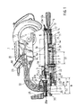
- slide compound saw 1 may generally include a base 2, a table 3b and a turntable 5 rotatably mounted on or within the base 2 and/or table 3b.
- a turntable 5 rotatably mounted on or within the base 2 and/or table 3b.
- an upper surface 5b of the turntable is flush (or substantially flush) with the upper surface of the table 3b.
- a circular saw unit 20 may be pivotally disposed above the turntable 5.
- the circular saw unit 20 is preferably designed to cut a workpiece W that is supported by the table 3b and/or the turntable 5.
- the workpiece W may be placed on the upper surface 5b of the turntable 5 and one side of the workpiece W preferably contacts a substantially vertically-oriented surface 3a of a fence 3. That is, the fence 3 preferably extends substantially perpendicularly from the table surface and the turntable surface 5b.
- a workpiece holder or vice optionally may fixedly hold or retain the workpiece W against the upper surface of the table 3b, so that the workpiece W can be fixed in position relative to the table 3b.
- the workpiece W With the workpiece W thus fixed in position, the workpiece W can be cut by a circular saw 21 that is rotatably mounted within the saw unit 20 and is rotatably driven by a motor (not shown).
- a circular saw 21 that is rotatably mounted within the saw unit 20 and is rotatably driven by a motor (not shown).
- the saw unit 20 is shown in the lowermost pivot (i.e., cutting) position.
- a blade receiving slot 5a is preferably defined within the turntable 5 for receiving a lower portion of the saw blade 21 during the cutting operation of the workpiece W.
- the blade receiving slot 5a may be at least partially defined within a turntable extension 6 that radially extends outward from the outer periphery of the turntable 5.
- the fence 3 may be separated into two discrete portions and the two fence portions are preferably disposed on respective sides of the blade receiving slot 5a.
- the blade surface of saw blade 21 may be positioned so as to extend substantially perpendicular to the vertically-oriented surface 3a of the fence 3. Therefore, the workpiece W can be cut in a direction perpendicular to the longitudinal direction of the workpiece W.
- the turntable 5 and the saw unit 20 are preferably designed to rotate together relative to the fence 3. Therefore, an oblique or miter cutting operation can be performed so as to cut the workpiece W obliquely relative to the longitudinal direction of the workpiece W.
- the rotational center of the turntable 5 may be positioned just below the central point of the vertically-oriented surface 3a.
- the turntable 5 can rotate about a vertical support shaft 7 that may be positioned below the central point.
- the cut angle of the workpiece W may be changed in response to the rotational position of the turntable 5 and the saw unit 20 relative to the vertically-oriented surface 3a of the fence 3.
- a turntable lock 10 may serve to releasably fix the turntable 5 in position relative to the base 2 and the table 3b.
- the turntable lock 10 may include a first lock pin 11 and a second lock pin 12.
- the first lock pin 11 may serve as a positive lock pin for setting the rotational position of the turntable 5 relative to the base 2.
- a plurality of predetermined rotational positions may be spaced at predetermined angular intervals.
- the base 2 may include a side wall 4 that has a substantially semicircular configuration with respect to the support shaft 7.
- a plurality of notches 4a may be defined within the side wall 4 at predetermined intervals in the circumferential or peripheral direction.
- the predetermined intervals may be, e.g., regularly spaced intervals or may be intervals that correspond to the most common angular (miter) cuts performed by the saw 1.
- the second lock pin 12 may serve to releasably fix the turntable 5 in the selected (miter) position.
- a spring 14 may bias the first lock pin 11 toward the side wall 4.
- the biasing force of the spring 14 will cause the first lock pin 11 to engage the respective notches 4a.
- An operation lever 13 may include a tab or flange 13a that is operably coupled to the first lock pin 11.
- the second lock pin 12 may threadably engage the turntable 5. In this case, by rotating the second lock pin 12 in a first direction, the second lock pin 12 will press against the side wall 4 via a pressing plate 15. Therefore, the rotational position of the turntable 5 can be locked with respect to the base 2 and table 3b. The locked state of the turntable 5 can be released by rotating the second lock pin 12 in the opposite (second) direction.
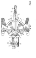
- a pair of parallel slide bars (e.g., first slide bars) 31 may be slidably coupled to the turntable 5 and may extend substantially in the horizontal direction. That is, the slide bars 31 preferably extend in a direction that is substantially perpendicular to the vertically-oriented surface.3a. As shown in FIGS. 1 and 2, the left-side portions of the slide bars 31 may be slidably coupled to an arm holder 24. Further, an arm 22 may be supported on the arm holder 24 and the saw unit 20 may be supported by the arm 22. Although two slide bars 31 are utilized in the first representative embodiment, only one slide bar 31 is necessary to provide the function of enabling the saw unit 20 to slide relative to the base 2 and the table 3b.
- the arm 22 may extend or project over the slide bars 31 toward a position above the turntable 5.
- a support rod 23 may be disposed within a front end portion of the arm 22 and the saw unit 20 may pivot about the support rod 23.
- the support rod 23 may serve as a hinge and the saw unit 20 can pivot or rotate about the hinge.
- a return spring (not shown in the first representative embodiment) normally biases the saw unit 20 toward in an uppermost or resting position (an upper stroke end). Therefore, in order to cut a workpiece W, the operator will typically move or pivot the saw unit 20 downward from the uppermost position against the biasing force of the return spring.
- a horizontally-disposed rod 25 may be utilized to permit the arm 22 to pivot laterally relative to the arm holder 24.
- an arc-shaped guide surface 24a may be defined on the arm holder 24 about the pivotal axis of the arm 22 Therefore, pivotal movement of the arm 22 relative to the arm holder 24 can be prevented when the arm 22 is slidably supported by the arc-shaped guide surface 24a.
- the axis of the horizontally-disposed rod 25 may be positioned, e.g., above the upper surface Sb of the turntable 5 and may be substantially aligned, e.g., with the blade slot 5a.
- the horizontally-disposed rod 25 may threadably engage a threaded hole 25a defined within the lower end portion of the arm 22.
- An operation lever 26 may be attached to one end of the horizontally-disposed rod 25. Therefore, by rotating the operation lever 26 and thus the horizontally-disposed rod 25 in one direction, the arm 22 can be fixed or locked in position relative to the arm holder 24. When the horizontally-disposed rod 25 is rotated in the opposite direction, the arm 22 will be released and will be free to pivot relative to the arm holder 24.
- a first slide mechanism 30 may enable the saw unit 20 to linearly move or slide in a direction parallel, or substantially parallel, to the upper surface Sb of the turntable 5 within a first slidable distance (S1)
- the pair of parallel slide bars 31 may be included within the slide mechanism 30.
- a pair of first bearing members 32 may slidably support the respective front portions of the slide bars 31 with respect to the turntable 5.
- the first bearing members 32 may be disposed within the turntable 5 (i.e., below the upper surface 5b of the turntable 5). In this case, the slide bars 31 will slide below the upper surface 5b of the turntable 5.
- the slide bars 31 and the first bearing members 32 also may be disposed above the turntable surface 5b.
- the first bearing members 32 preferably include a pair of linear ball bearings for slidably receiving the respective slide bars 31.
- the first bearing members 32 may be linear slide bearings.
- the arm holder 24 may extend between or across the rear end portions of the slide bars 31.
- a pair of second bearing members 33 may be disposed within the arm holder 24.
- the second bearing members 33 may include a pair of linear ball bearings that slidably receive the rear end portions of the respective slide bars 31.
- the second bearing members 32 also may be linear slide bearings and preferably slidably support the arm holder 24 with respect to the slide bars 31.
- each of the slide bars 31 may have a circular, or substantially circular, cross section, although the slide bars 31 may have other configurations.
- a front tie bar 34 may join the front end portions of the slide bars 31 and a rear tie bar 35 may join the rear end portions of the slide bars 31.
- Front and rear stoppers 36 and 37 may be defined within the turntable 5 so as contact the front tie bar 34 and define a first (discrete) movable (slidable) range (S1 of the slide bars 31. That is, the distance between the front and rear stoppers 36 and 37 of the first slide mechanism 30 may define the movable or slidable distance (S1 in this embodiment.
- the slidable distance (S1) will be defined by the distance between the first and second stoppers 36 and 37 minus the length of the first bearing member 32.
- the rear stopper 37 may be defined on a boss portion of the turntable 5 that receives the vertically disposed shaft 7.
- the rear tie bar 35 and stopper rings 38 may be attached to the slide bars 31 at a substantially middle position along the axial direction of the slide bars 31.
- a second (discrete) movable (slidable) range (S2) of the arm holder 24 relative to the slide bars 31 may be defined by the distance (B) between the rear tie bar 35 and the stopper rings 38 minus the length (b) of the second bearing members 33, because the second bearing members 33 are disposed within the maximum slidable distance (B) of the arm holder 24 relative to the slide bars 32.
- the second bearing members 33 optionally may be disposed within an outer casing 33a that has a front end (right end as viewed in FIG. 2) that opposes or faces the stopper ring 38 and a rear end (left end as viewed in FIG. 2) that opposes or faces the rear tie bar 35.
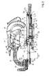
- the saw unit 20 can move in the horizontal (parallel) direction relative to the turntable 5 along two distinct (i.e., physically separated) sliding ranges. That is, the slide bars 31 may move or slide relative to the turntable 5 within the first slidable range (S1) and the arm holder 24 can further move or slide relative to the slide bars 31 within the second slidable range (S2). Thus, the slide bar 31 can move or slide up to a distance S1 relative to the turntable 5, and the arm holder 24 can move or slide up to a distance S2 relative to the slide bars 31, as shown in FIGS. 1 and 2.
- a first lock mechanism 41A may serve to fix the position of the slide bars 31 relative to the turntable 5.
- a second lock mechanism 41B may serve to fix the arm holder 24 in position relative to the slide bars 31.
- the position of the saw unit 20 relative to the turntable 5 in the longitudinal direction of the slide bars 31 may be fixed by the first and second lock mechanisms 41A and 41B. Because the first and second lock mechanisms 41A and 41B may be constructed in substantially the same manner, it is only necessary to describe the first lock mechanism 41A in further detail.
- the first lock mechanism 41A may include an auxiliary ring 43 that is slidably fitted onto one of the slide bars 31.
- a stopper screw 42 may be inserted into the turntable 5 from the lower side.
- the stopper screw 42 may be screwed or threaded into the auxiliary ring 43 in the diametrical or radial direction so as to fix the auxiliary ring 43 in position relative to the turntable 5.
- a lock screw 44 may be inserted into the turntable 5 from the upper side and may be screwed into the auxiliary ring 43 in a position opposite to the stopper screw 42.
- the end or tip portion of the lock screw 44 can abut or contact the outer surface of the slide bar 31, so that the slide bars 31 can be releasably fixed or locked in position relative to the turntable 5.
- the second lock mechanism 41B may have substantially the same construction as the first lock mechanism 41A. Therefore, the arm holder 24 can be fixed in position relative to the slide bars 31 by tightening a lock screw 44 of the second lock mechanism 41B.
- the saw unit 20 may linearly move or slide relative to the turntable 5 along (1) a distance S1 by sliding the slide bars 31 relative to the turntable 5 and (2) a further distance S2 by sliding the arm holder 24 relative to the slide bars 31. Therefore, in order to cut a workpiece W set onto the turntable 5, the operator may first pivot the saw unit 20 downward about the support shaft 23 to cut the front portion of the workpiece W. In this step, the saw unit 20 is preferably positioned at the forward most position (rightmost position as viewed in FIG. 1). The operator may then push the saw unit 20 rearward (leftward as viewed in FIG. 1), so that the workpiece W can be cut along the entire length of the workpiece W in the forward and rearward directions.
- the saw unit 20 can move or slide by (or up to) the combined distance (S1 + S2), in which the distance S1 is the movable or slidable distance of slide bars 31 relative to turntable 5 and the distance S2 is the movable or slidable distance of arm holder 24 relative to the slide bars 31.
- S1 + S2 the combined distance
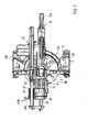
- a second representative slide mechanism 130 will now be described with reference to FIG. 4, in which the same reference numerals are utilized for the same elements as FIGS. 1-3. Because the slide mechanism 130 may be utilized with the saw 1 of FIGS 1-3, a complete description of a saw including slide mechanism 130 is not necessary.
- the second representative slide mechanism 130 may include a pair of first slide bars 51, which are preferably disposed in parallel.
- the first slide bars 51 preferably may be substantially hollow and cylindrical in cross section, although other configurations are, of course, possible with the present teachings.
- the front ends (right ends as viewed in FIG. 4) of the first slide bars 51 may be slidably mounted within the turntable 5 and may be slidably supported by first bearing members 32, which may include linear ball bearings as in the first representative embodiment.
- Front and rear stoppers 51a and 51b may be attached to the outer periphery of each of the first slide bars 51. Further, the front and rear stoppers 51a and 51b may respectively oppose the front and rear ends of the outer casing 32a of the first bearing member 32 along the longitudinal direction of the first slide bars 51. The front and rear stoppers 51a and 51b define the maximum slidable distance (A) along the first slide bar 51. The length (a) of the first bearing member 32 must be subtracted from (A) in order to obtain the first movable or slidable range (S1) for the second representative embodiment.
- front and rear stoppers 52a and 52b may be attached to or defined along the outer periphery of each of the second slide bars 52. Further, the front and rear stoppers 52a and 52b may respectively oppose the front and rear ends of the outer casing 33a of the second bearing member 33 along the longitudinal direction of the second slide bars 52. The front and rear stoppers 52a and 52b define the maximum slidable distance (B) along the second slide bar 52. The length (b) of the first bearing member 33 must be subtracted from the distance (B) in order to obtain the second movable or slidable range (S2) for the second representative embodiment.
- the saw unit 20 of the second representative embodiment may be linearly moved or slid up to or within a combined distance (range) of S1 plus S2, because the first slide bars 51 can slide or move by a distance or range S1 relative to the turntable 5 and the second slide bars 52 can slide or move by a distance or range S2 relative to the first slide bars 51.
- the saw unit 20 can move in the horizontal (parallel) direction relative to the turntable 5 along two discrete slidable or movable ranges.
- a third slidable range (S3) will be provided.
- the combined sliding distance can be increased (e.g., at least up to S1 plus S2) while still maintaining a compact configuration for the saw 1. That is, it is not necessary to increase the length of slide bars 51 in order to provide a longer sliding range.
- the sliding movement may be performed in two discrete steps (i.e., first sliding by or up to the distance S1, stopping the sliding movement and then sliding by or up to the distance S2) or the sliding movement along or within the distance (range) S1 plus S2 (or S1 plus S2 plus optionally S3) may be performed in one continuous motion.
- the slide mechanism 130 may have a relatively compact construction and may occupy a smaller space than the slide mechanism 30 of the first representative embodiment.
- a third representative embodiment will now be described with reference to FIG. 5, in which the same reference numerals will be utilized for the same elements as the first and second representative embodiments.
- the slide compound saw 100 of the third representative embodiment is different from the first representative embodiment in that the arm holder 24 is fixedly secured to the rear ends of the (first) slide bars 31. Further, a slide support 61 and a pair of upper (second) slider bars 62 slidably support the saw unit 20 with respect to the arm holder 24.
- the front ends of the (first) slide bars 31 may be slidably mounted within the turntable 5, and the first lock mechanism 41A may serve to releasably fix the position of the slide bars 31 relative to the turntable 5.
- stoppers may be attached to or defined on the upper slide bars 62 in order to define the maximum movable or slidable distance (B) of the upper slide bars 62.
- the length (b) of the arm holder 24 must be subtracted from the distance (B).
- the movable or slidable range (S2) of the upper slide bars 62 relative to the arm holder 24 may be defined as (B) - (b), i.e., the distance (B) between the stoppers disposed on the upper slide bars 62 minus the length (b) of the arm holder 24.
- the respective rear portions of the upper slide bars 62 optionally may be covered by a bellows-like dust cover 64 that can expand and contract.
- the front end of the dust cover 64 may be attached to the rear end of the slide support 61 and the rear end of the dust cover 64 may be attached to the rear end of the corresponding upper slide bars 62.
- a bracket 63 may be attached to the front ends of the upper slide bars 62. Further, the support rod 23 and the bracket 63 may pivotally support the saw unit 20. That is, the saw unit 20 may pivot or rotate towards the workpiece W via the bracket 63 and the support rod 23 (collectively, a hinge). Further, a return (coil) spring 65 may upwardly bias the saw unit 20 toward the uppermost or resting position.
- a dust duct 66 may be provided to direct dust away from the upper surface 5b and into, e.g., a dust collection receptacle (not shown).
- the saw unit 20 can move or slide by a distance S1 plus S2. That is, the (first) slide bars 31 can move or slide relative to the turntable 5 by the distance S1 and the upper (second) slide bars 62 can move or slide relative to the arm holder 24 by the distance S2.
- the saw unit 20 can move or slide relative to the turntable 5 by the sums (S1 + S2) of the movable distance S1 of the slider bars 31 relative to the turntable 5 and the movable distance S2 of the upper slide bars 62 relative to the arm holder 24. Therefore, also in the third representative embodiment, the saw unit 20 can slide along a relatively large distance without increasing the size of the turntable 5.
- the arm holder 24 may be movably coupled to the slide bars 31, as in the first representative embodiment, in order to define a third slidable range (S3) of the arm holder 24 relative to the slide bars 31.
- the second lock mechanism 141B can be manufactured at a lower cost than the lock mechanisms 41A or 41B.
- slide compound saws may optionally utilize the second lock mechanism 141B to prevent the holder arm 24 from moving or sliding in the axial (longitudinal) direction relative to the upper slide support 61.
- the first lock mechanism 41A must bear the torsional force that is applied to the slide bars 31 when a bevel cutting operation is performed with the saw unit 20 disposed in a position inclined from the vertical orientation. Therefore, the first lock mechanism 41A is preferably sufficiently resilient to withstand this force.
- the arm holder 24 of the fourth representative embodiment also may be movably coupled to the slide bars 31, as in the first representative embodiment, in order to define a third slidable range (S3) of the arm holder 24 relative to the slide bars 31.
- S3 third slidable range
- the number and the cross-sectional configuration of the first and second slide bars 31, 51, 52 or 62 may be selectively and suitably determined.
- the present teachings are not limited to cylindrical-shaped slide bars, as polygonal-shaped bars (e.g., rectangular-shaped bars) also may be utilized.
- the saw unit 20 may move or slide along three or more discrete slidable ranges. That is, three or more sets of sliding distances (e.g., S1, S2 and S3) optionally made be utilized with the present teachings.
Landscapes
- Engineering & Computer Science (AREA)
- Mechanical Engineering (AREA)
- Sawing (AREA)
Abstract
Description
It is explicitly stated that all features disclosed in the description and/or the claims are intended to be disclosed separately and independently from each other for the purpose of original disclosure as well as for the purpose of restricting the claimed invention independent of the compositions of the features in the embodiments and/or the claims. It is explicitly stated that all value ranges or indications of groups of entities disclose every possible intermediate value or intermediate entity for the purpose of original disclosure as well as for the purpose of restricting the claimed invention.
Claims (16)
- A slide compound saw (1, 100, 150), comprising:a table (3b) defining a table surface,a saw unit (20) pivotable relative to the table surface,a first slide bar (31, 51, 251, 351) slidably coupling the saw unit to the table and disposed substantially in parallel with the table surface, wherein the first slide bar defines a first slidable range (S1 of the saw unit in a direction substantially parallel to the table surface, andsliding means (24, 33, 35, 38, 52, 61, 62, 252, 352) for slidably coupling the first slide bar to the saw unit, wherein the sliding means defines second slidable range (S2) of the saw unit in the direction substantially parallel to the table surface, wherein the saw unit is slidable within a slidable range S1 plus S2 in the direction substantially parallel to the table surface.
- A slide compound saw (1, 100, 150), comprising:a table (3b) defining a table surface,a saw unit (20),a first slide bar (31, 51, 251, 351) defining a first discrete slidable range (S1) in a direction substantially parallel to the table surface,means (32, 36, 37) for sliding the saw unit relative to the table via the first slide bar and a first slide mechanism (30) within the first discrete slidable range (S1), andsliding means (24, 33, 35, 38, 52, 61, 62, 252, 352) for sliding the saw unit in substantially the same direction as the first slide bar within a second discrete slidable range (S2), the sliding means supporting the saw unit.
- A slide compound saw as in claim 1 or 2, wherein the sliding means includes an arm support (24) pivotally supporting the saw unit.
- A slide compound saw as in claim 3, wherein the arm support is fixedly secured to the first slide bar.
- A slide compound saw as in claim 3, wherein the arm support is slidably coupled to the first slide bar.
- A slide compound saw as in claim 1 or 2, wherein the sliding means is slidably and concentrically disposed with respect to the first slide bar.
- A slide compound saw as in claim 6, wherein the sliding means comprises a second slide bar (52, 252, 352) slidably disposed within or around the first slide bar and an arm support (24) coupling the second slide bar to the saw unit.
- A slide compound saw as in claim 1 or 2, wherein the sliding means comprises an arm support (24) fixedly coupled to the first slide bar, an upper slide support (61) coupled to the arm support and a second slide bar (62) slidably disposed within the upper slide support, wherein the second slide bar extends substantially parallel to the first slide bar and the saw unit is coupled to the second slide bar.
- A slide compound saw as in any previous claim, wherein the sliding means further comprises means (25, 26) for releasably locking the saw unit in a bevel cutting position relative to the table surface.
- A slide compound saw as in any previous claim, further comprising a turntable (5) disposed within the table and rotatably coupling the first slide bar to the table.
- A slide compound saw as in any previous claim, further comprising a hinge (23) pivotally coupling the saw unit to the sliding means.
- A slide compound saw as in any previous claim, further comprising means (41A, 41B, 141B) for releasably locking the first slide bar relative to the sliding means and/or for releasably locking the sliding means relative to the saw unit.
- A slide compound saw as in any previous claim, further comprising means for defining a third sliding range (S3) between the saw unit and the table.
- A method for sliding a saw unit (20) relative to a table (3b), comprising:sliding the saw unit via a first slide bar (31, 51, 251, 351) and a first slide mechanism (30) relative to the table in a direction substantially parallel to a surface of the table within a first discrete sliding range (S1), andsliding a second slide mechanism (24, 33, 35, 38, 52, 61, 62, 252, 352) relative to the first slide mechanism in substantially the same direction as the first slide mechanism within a second discrete sliding range (S2).
- A method as in claim 14, further comprising:after sliding the saw unit relative to the table in the direction substantially parallel to the table surface within the first discrete sliding range, releasably locking (41A) the position of the first slide mechanism or first slide bar relative to the table.
- A method as in claim 14 or 15, further comprising:after sliding the second slide mechanism relative to the first slide mechanism in substantially the same direction as the first slide mechanism within the second discrete sliding range, releasably locking (41B, 141B) the position of the second slide mechanism relative to the first slide mechanism or the first slide bar.
Priority Applications (7)
| Application Number | Priority Date | Filing Date | Title |
|---|---|---|---|
| DE60229176T DE60229176D1 (en) | 2002-06-07 | 2002-06-07 | Crosscut and miter saw |
| EP20020012713 EP1369196B8 (en) | 2002-06-07 | 2002-06-07 | Slide saw and method of using the same |
| EP06013608A EP1700658B1 (en) | 2002-06-07 | 2002-06-07 | Sliding Saw |
| DE2002614141 DE60214141T2 (en) | 2002-06-07 | 2002-06-07 | Crosscut and miter saw |
| US10/163,636 US7387056B2 (en) | 2002-06-07 | 2002-06-07 | Slide compound saws |
| ES02012713T ES2271147T3 (en) | 2002-06-07 | 2002-06-07 | SLIDING COMPOUND SAWS. |
| US12/153,035 US20080210074A1 (en) | 2002-06-07 | 2008-05-13 | Slide compound saws |
Applications Claiming Priority (2)
| Application Number | Priority Date | Filing Date | Title |
|---|---|---|---|
| EP20020012713 EP1369196B8 (en) | 2002-06-07 | 2002-06-07 | Slide saw and method of using the same |
| US10/163,636 US7387056B2 (en) | 2002-06-07 | 2002-06-07 | Slide compound saws |
Related Child Applications (1)
| Application Number | Title | Priority Date | Filing Date |
|---|---|---|---|
| EP06013608A Division EP1700658B1 (en) | 2002-06-07 | 2002-06-07 | Sliding Saw |
Publications (3)
| Publication Number | Publication Date |
|---|---|
| EP1369196A1 true EP1369196A1 (en) | 2003-12-10 |
| EP1369196B1 EP1369196B1 (en) | 2006-08-23 |
| EP1369196B8 EP1369196B8 (en) | 2008-03-26 |
Family
ID=32109131
Family Applications (1)
| Application Number | Title | Priority Date | Filing Date |
|---|---|---|---|
| EP20020012713 Expired - Lifetime EP1369196B8 (en) | 2002-06-07 | 2002-06-07 | Slide saw and method of using the same |
Country Status (2)
| Country | Link |
|---|---|
| US (2) | US7387056B2 (en) |
| EP (1) | EP1369196B8 (en) |
Cited By (2)
| Publication number | Priority date | Publication date | Assignee | Title |
|---|---|---|---|---|
| EP1690622A3 (en) * | 2005-02-15 | 2006-10-11 | GMCA PTY Ltd | Powered saw apparatus |
| WO2007099884A1 (en) * | 2006-02-22 | 2007-09-07 | Hitachi Koki Co., Ltd. | Miter saw |
Families Citing this family (30)
| Publication number | Priority date | Publication date | Assignee | Title |
|---|---|---|---|---|
| US20040112190A1 (en) * | 2002-11-26 | 2004-06-17 | Hollis Michael Chad | Bevel angle locking actuator and bevel angle locking system for a saw |
| CN100376349C (en) * | 2004-02-23 | 2008-03-26 | 胡桂强 | Electric miter cutting machine |
| US20050098010A1 (en) * | 2003-07-30 | 2005-05-12 | Ning Bo Yang Ming Electric Tools Company, Ltd. | Electric miter saw |
| JP4534549B2 (en) * | 2004-03-26 | 2010-09-01 | 日立工機株式会社 | Tabletop cutting machine |
| JP2005279933A (en) * | 2004-03-26 | 2005-10-13 | Hitachi Koki Co Ltd | Tabletop cutting machine |
| JP4483488B2 (en) * | 2004-09-02 | 2010-06-16 | 日立工機株式会社 | Tabletop cutting machine |
| JP4759276B2 (en) * | 2005-01-20 | 2011-08-31 | 日立工機株式会社 | Tabletop cutting machine |
| US7611401B1 (en) * | 2005-09-30 | 2009-11-03 | Column & Post, Inc. | Mount for a belt-sanding apparatus |
| US8322261B2 (en) * | 2010-06-09 | 2012-12-04 | Robert Bosch Gmbh | Locking construction for a miter saw having a hinged linear guide mechanism |
| US8857303B2 (en) | 2005-11-22 | 2014-10-14 | Robert Bosch Gmbh | Locking mechanism for miter saw with hinge linkage linear guide |
| US8631734B2 (en) | 2005-11-22 | 2014-01-21 | Robert Bosch Gmbh | Glide movement controller and power miter saw including such controller |
| US8752461B2 (en) | 2005-11-22 | 2014-06-17 | Robert Bosch Gmbh | Hinge connections and power miter saw with hinge linkage linear guide including such hinge connections |
| GB0713817D0 (en) * | 2007-07-17 | 2007-08-29 | Gmca Pty Ltd | Saw with circular blade |
| JP5103083B2 (en) * | 2007-07-26 | 2012-12-19 | 株式会社マキタ | Tabletop cutting machine |
| CN101821066B (en) * | 2007-10-12 | 2012-05-23 | 利优比株式会社 | Slide type cutting machine |
| JP5154274B2 (en) * | 2008-03-21 | 2013-02-27 | 株式会社マキタ | Tabletop cutting machine |
| JP5179232B2 (en) | 2008-03-21 | 2013-04-10 | 株式会社マキタ | Tabletop cutting machine |
| USD597569S1 (en) * | 2008-08-20 | 2009-08-04 | Makita Corporation | Miter saw |
| JP5666094B2 (en) * | 2009-01-30 | 2015-02-12 | 株式会社マキタ | Tabletop cutting machine |
| JP5530649B2 (en) * | 2009-03-26 | 2014-06-25 | 株式会社マキタ | Slide marnoco |
| CN201841314U (en) * | 2010-08-03 | 2011-05-25 | 南京德朔实业有限公司 | Pull rod locking device of miter saw |
| US8671811B2 (en) | 2011-09-30 | 2014-03-18 | Robert Bosch Gmbh | Pivoting saw system |
| US9649703B2 (en) | 2012-03-15 | 2017-05-16 | Rexon Industrial Corp., Ltd. | Circular saw with a moving mechanism |
| US9339877B2 (en) * | 2012-07-04 | 2016-05-17 | Sumec Hardware & Tools Co., Ltd. | Electric mitre saw |
| CN102728889B (en) * | 2012-07-11 | 2014-11-12 | 宁波德丰动力科技有限公司 | Cutting machine |
| US9283628B2 (en) * | 2013-03-08 | 2016-03-15 | Black & Decker Inc. | Chop saw with improved storage mode |
| US8898913B1 (en) * | 2014-06-17 | 2014-12-02 | Michael J. Lones | Masonry circular saw stabilizing and supporting shoe |
| EP4201565A3 (en) | 2015-02-25 | 2023-09-20 | Milwaukee Electric Tool Corporation | Miter saw |
| US11213903B2 (en) * | 2020-01-03 | 2022-01-04 | Dmt Holdings, Inc. | Sawing machine |
| GB2619777A (en) * | 2022-06-17 | 2023-12-20 | Evolution Power Tools Ltd | An improved chop saw |
Citations (6)
| Publication number | Priority date | Publication date | Assignee | Title |
|---|---|---|---|---|
| WO1983003569A1 (en) * | 1982-04-14 | 1983-10-27 | Lavis, Leon, Joseph | Power tool mounting assembly |
| US5054352A (en) * | 1989-01-17 | 1991-10-08 | Makita Electric Wroks, Ltd. | Miter saw |
| US5524516A (en) * | 1993-02-19 | 1996-06-11 | Makita Corporation | Miter saw |
| JPH1190730A (en) * | 1997-07-23 | 1999-04-06 | Makita Corp | Stopper device for sliding mechanism |
| JP2002200601A (en) * | 2000-12-28 | 2002-07-16 | Makita Corp | Sliding circular sawing machine |
| US20020144582A1 (en) * | 2001-04-10 | 2002-10-10 | He Cai Bai | Extendible compound miter saw |
Family Cites Families (14)
| Publication number | Priority date | Publication date | Assignee | Title |
|---|---|---|---|---|
| US54352A (en) * | 1866-05-01 | Improved bench-vise | ||
| US869142A (en) * | 1907-08-08 | 1907-10-22 | James B Patterson | Suspension-couch. |
| US1638122A (en) * | 1926-04-16 | 1927-08-09 | Pittsburgh Erie Saw Company | Power saw |
| US2628643A (en) * | 1948-07-31 | 1953-02-17 | Ralph R Roemer | Wood sawing machine |
| US3483901A (en) * | 1967-12-12 | 1969-12-16 | Kyle Ray | Electric power saw miter machine |
| US4587875A (en) * | 1985-05-02 | 1986-05-13 | Theodore Deley | Portable sawing device utilizing a circular power saw |
| JPH0518082Y2 (en) | 1987-02-20 | 1993-05-14 | ||
| JPH0442320U (en) * | 1990-07-31 | 1992-04-10 | ||
| US5241888A (en) * | 1992-07-31 | 1993-09-07 | Rexon Industrial Corporation, Ltd. | Slidable compound miter saw |
| US5791224A (en) * | 1994-03-24 | 1998-08-11 | Ryobi Limited | Circular sawing machine |
| JP3320950B2 (en) * | 1995-06-15 | 2002-09-03 | 株式会社マキタ | Support structure of slide bar on slide marunoco |
| JP3283745B2 (en) * | 1996-02-05 | 2002-05-20 | 株式会社マキタ | Power tool operating lever |
| JP3490275B2 (en) * | 1998-01-12 | 2004-01-26 | 株式会社マキタ | Slide marunoco |
| JP3760376B2 (en) * | 2001-02-22 | 2006-03-29 | 株式会社村田製作所 | Fiber optic connector |
-
2002
- 2002-06-07 EP EP20020012713 patent/EP1369196B8/en not_active Expired - Lifetime
- 2002-06-07 US US10/163,636 patent/US7387056B2/en not_active Expired - Lifetime
-
2008
- 2008-05-13 US US12/153,035 patent/US20080210074A1/en not_active Abandoned
Patent Citations (6)
| Publication number | Priority date | Publication date | Assignee | Title |
|---|---|---|---|---|
| WO1983003569A1 (en) * | 1982-04-14 | 1983-10-27 | Lavis, Leon, Joseph | Power tool mounting assembly |
| US5054352A (en) * | 1989-01-17 | 1991-10-08 | Makita Electric Wroks, Ltd. | Miter saw |
| US5524516A (en) * | 1993-02-19 | 1996-06-11 | Makita Corporation | Miter saw |
| JPH1190730A (en) * | 1997-07-23 | 1999-04-06 | Makita Corp | Stopper device for sliding mechanism |
| JP2002200601A (en) * | 2000-12-28 | 2002-07-16 | Makita Corp | Sliding circular sawing machine |
| US20020144582A1 (en) * | 2001-04-10 | 2002-10-10 | He Cai Bai | Extendible compound miter saw |
Non-Patent Citations (2)
| Title |
|---|
| DATABASE WPI Section PQ Week 200268, Derwent World Patents Index; Class P54, AN 2002-631166, XP002219528 * |
| PATENT ABSTRACTS OF JAPAN vol. 1999, no. 09 30 July 1999 (1999-07-30) * |
Cited By (3)
| Publication number | Priority date | Publication date | Assignee | Title |
|---|---|---|---|---|
| EP1690622A3 (en) * | 2005-02-15 | 2006-10-11 | GMCA PTY Ltd | Powered saw apparatus |
| WO2007099884A1 (en) * | 2006-02-22 | 2007-09-07 | Hitachi Koki Co., Ltd. | Miter saw |
| US8127650B2 (en) | 2006-02-22 | 2012-03-06 | Hitachi Koki Co., Ltd. | Miter saw |
Also Published As
| Publication number | Publication date |
|---|---|
| US20030226436A1 (en) | 2003-12-11 |
| US20080210074A1 (en) | 2008-09-04 |
| EP1369196B1 (en) | 2006-08-23 |
| US7387056B2 (en) | 2008-06-17 |
| EP1369196B8 (en) | 2008-03-26 |
Similar Documents
| Publication | Publication Date | Title |
|---|---|---|
| EP1369196A1 (en) | Slide compound saws | |
| EP2078575B1 (en) | Cutting device | |
| EP2554311B1 (en) | Table cutting machine | |
| US6758123B2 (en) | Bevel angle detent system for a compound miter saw | |
| US5437214A (en) | Miter saw | |
| EP0941797B1 (en) | Sliding mitre saw | |
| CN101875204B (en) | Miter saw with working surface extension | |
| EP2103371B1 (en) | Table cutting machine | |
| AU2010241276B2 (en) | Power tool including a miter lock and saw assembly | |
| EP1400297B1 (en) | Slide miter saw | |
| EP2145711A2 (en) | Cutting devices | |
| US20090301277A1 (en) | Saw With Moveable Material Support Surface | |
| CA2183035A1 (en) | Lower blade guard actuating mechanism for a slide compound miter saw | |
| US8490528B2 (en) | Cutting device having a positioning mechanism | |
| US20100043615A1 (en) | Miter Assembly for Miter Saws | |
| US20090026346A1 (en) | Support leg devices and cutting tools having the support leg devices | |
| AU2006201714A1 (en) | Bevel lock assembly for miter saws | |
| EP4337407A1 (en) | Miter saw | |
| EP1568432B1 (en) | Miter saw | |
| US9533361B2 (en) | Cutting machines | |
| EP1700658B1 (en) | Sliding Saw | |
| JP4454842B2 (en) | Slide circular saw | |
| JP3193224B2 (en) | Slide marunoco | |
| JP5760602B2 (en) | Sliding tabletop cutting machine | |
| WO2022241399A1 (en) | Miter saw |
Legal Events
| Date | Code | Title | Description |
|---|---|---|---|
| PUAI | Public reference made under article 153(3) epc to a published international application that has entered the european phase |
Free format text: ORIGINAL CODE: 0009012 |
|
| AK | Designated contracting states |
Kind code of ref document: A1 Designated state(s): AT BE CH CY DE DK ES FI FR GB GR IE IT LI LU MC NL PT SE TR |
|
| AX | Request for extension of the european patent |
Extension state: AL LT LV MK RO SI |
|
| 17P | Request for examination filed |
Effective date: 20040109 |
|
| AKX | Designation fees paid |
Designated state(s): DE ES FR GB IT |
|
| GRAP | Despatch of communication of intention to grant a patent |
Free format text: ORIGINAL CODE: EPIDOSNIGR1 |
|
| GRAS | Grant fee paid |
Free format text: ORIGINAL CODE: EPIDOSNIGR3 |
|
| GRAA | (expected) grant |
Free format text: ORIGINAL CODE: 0009210 |
|
| AK | Designated contracting states |
Kind code of ref document: B1 Designated state(s): DE ES FR GB IT |
|
| PG25 | Lapsed in a contracting state [announced via postgrant information from national office to epo] |
Ref country code: IT Free format text: LAPSE BECAUSE OF FAILURE TO SUBMIT A TRANSLATION OF THE DESCRIPTION OR TO PAY THE FEE WITHIN THE PRESCRIBED TIME-LIMIT;WARNING: LAPSES OF ITALIAN PATENTS WITH EFFECTIVE DATE BEFORE 2007 MAY HAVE OCCURRED AT ANY TIME BEFORE 2007. THE CORRECT EFFECTIVE DATE MAY BE DIFFERENT FROM THE ONE RECORDED. Effective date: 20060823 |
|
| REG | Reference to a national code |
Ref country code: GB Ref legal event code: FG4D |
|
| RTI2 | Title (correction) |
Free format text: SLIDE SAW AND METHOD OF USING THE SAME |
|
| REF | Corresponds to: |
Ref document number: 60214141 Country of ref document: DE Date of ref document: 20061005 Kind code of ref document: P |
|
| ET | Fr: translation filed | ||
| REG | Reference to a national code |
Ref country code: ES Ref legal event code: FG2A Ref document number: 2271147 Country of ref document: ES Kind code of ref document: T3 |
|
| PLBE | No opposition filed within time limit |
Free format text: ORIGINAL CODE: 0009261 |
|
| STAA | Information on the status of an ep patent application or granted ep patent |
Free format text: STATUS: NO OPPOSITION FILED WITHIN TIME LIMIT |
|
| 26N | No opposition filed |
Effective date: 20070524 |
|
| REG | Reference to a national code |
Ref country code: FR Ref legal event code: PLFP Year of fee payment: 15 |
|
| REG | Reference to a national code |
Ref country code: FR Ref legal event code: PLFP Year of fee payment: 16 |
|
| REG | Reference to a national code |
Ref country code: FR Ref legal event code: PLFP Year of fee payment: 17 |
|
| PGFP | Annual fee paid to national office [announced via postgrant information from national office to epo] |
Ref country code: FR Payment date: 20210513 Year of fee payment: 20 Ref country code: DE Payment date: 20210511 Year of fee payment: 20 Ref country code: IT Payment date: 20210511 Year of fee payment: 20 |
|
| PGFP | Annual fee paid to national office [announced via postgrant information from national office to epo] |
Ref country code: GB Payment date: 20210512 Year of fee payment: 20 |
|
| PGFP | Annual fee paid to national office [announced via postgrant information from national office to epo] |
Ref country code: ES Payment date: 20210705 Year of fee payment: 20 |
|
| REG | Reference to a national code |
Ref country code: DE Ref legal event code: R071 Ref document number: 60214141 Country of ref document: DE |
|
| REG | Reference to a national code |
Ref country code: GB Ref legal event code: PE20 Expiry date: 20220606 |
|
| REG | Reference to a national code |
Ref country code: ES Ref legal event code: FD2A Effective date: 20220629 |
|
| PG25 | Lapsed in a contracting state [announced via postgrant information from national office to epo] |
Ref country code: GB Free format text: LAPSE BECAUSE OF EXPIRATION OF PROTECTION Effective date: 20220606 Ref country code: ES Free format text: LAPSE BECAUSE OF EXPIRATION OF PROTECTION Effective date: 20220608 |