EP1367858A1 - Installation de chauffage de produits, notamment visqueux - Google Patents
Installation de chauffage de produits, notamment visqueux Download PDFInfo
- Publication number
- EP1367858A1 EP1367858A1 EP02291336A EP02291336A EP1367858A1 EP 1367858 A1 EP1367858 A1 EP 1367858A1 EP 02291336 A EP02291336 A EP 02291336A EP 02291336 A EP02291336 A EP 02291336A EP 1367858 A1 EP1367858 A1 EP 1367858A1
- Authority
- EP
- European Patent Office
- Prior art keywords
- pipe
- electrodes
- product
- heating
- sections
- Prior art date
- Legal status (The legal status is an assumption and is not a legal conclusion. Google has not performed a legal analysis and makes no representation as to the accuracy of the status listed.)
- Granted
Links
- 238000010438 heat treatment Methods 0.000 title claims abstract description 36
- 238000009434 installation Methods 0.000 title claims abstract description 24
- 239000012777 electrically insulating material Substances 0.000 claims abstract description 6
- 239000011521 glass Substances 0.000 claims abstract description 4
- 239000000919 ceramic Substances 0.000 claims abstract description 3
- 238000002955 isolation Methods 0.000 claims description 4
- 239000004696 Poly ether ether ketone Substances 0.000 claims description 2
- 239000004743 Polypropylene Substances 0.000 claims description 2
- JUPQTSLXMOCDHR-UHFFFAOYSA-N benzene-1,4-diol;bis(4-fluorophenyl)methanone Chemical compound OC1=CC=C(O)C=C1.C1=CC(F)=CC=C1C(=O)C1=CC=C(F)C=C1 JUPQTSLXMOCDHR-UHFFFAOYSA-N 0.000 claims description 2
- 239000000805 composite resin Substances 0.000 claims description 2
- 239000002184 metal Substances 0.000 claims description 2
- 229920002530 polyetherether ketone Polymers 0.000 claims description 2
- -1 polypropylene Polymers 0.000 claims description 2
- 229920001155 polypropylene Polymers 0.000 claims description 2
- 239000003365 glass fiber Substances 0.000 claims 1
- 239000004033 plastic Substances 0.000 abstract 1
- 239000000047 product Substances 0.000 description 37
- 235000013305 food Nutrition 0.000 description 4
- 239000000463 material Substances 0.000 description 4
- 238000005086 pumping Methods 0.000 description 2
- 229910000831 Steel Inorganic materials 0.000 description 1
- 230000005540 biological transmission Effects 0.000 description 1
- 239000006227 byproduct Substances 0.000 description 1
- 238000010411 cooking Methods 0.000 description 1
- 230000007797 corrosion Effects 0.000 description 1
- 238000005260 corrosion Methods 0.000 description 1
- 238000010586 diagram Methods 0.000 description 1
- 238000003487 electrochemical reaction Methods 0.000 description 1
- 235000021183 entrée Nutrition 0.000 description 1
- 239000000835 fiber Substances 0.000 description 1
- 239000011810 insulating material Substances 0.000 description 1
- 238000009413 insulation Methods 0.000 description 1
- 238000004519 manufacturing process Methods 0.000 description 1
- 238000005259 measurement Methods 0.000 description 1
- 238000013021 overheating Methods 0.000 description 1
- 238000009928 pasteurization Methods 0.000 description 1
- 238000011084 recovery Methods 0.000 description 1
- 229910001220 stainless steel Inorganic materials 0.000 description 1
- 239000010935 stainless steel Substances 0.000 description 1
- 239000010959 steel Substances 0.000 description 1
- 230000001954 sterilising effect Effects 0.000 description 1
- 238000004659 sterilization and disinfection Methods 0.000 description 1
- 229940088594 vitamin Drugs 0.000 description 1
- 229930003231 vitamin Natural products 0.000 description 1
- 235000013343 vitamin Nutrition 0.000 description 1
- 239000011782 vitamin Substances 0.000 description 1
- 150000003722 vitamin derivatives Chemical class 0.000 description 1
Images
Classifications
-
- H—ELECTRICITY
- H05—ELECTRIC TECHNIQUES NOT OTHERWISE PROVIDED FOR
- H05B—ELECTRIC HEATING; ELECTRIC LIGHT SOURCES NOT OTHERWISE PROVIDED FOR; CIRCUIT ARRANGEMENTS FOR ELECTRIC LIGHT SOURCES, IN GENERAL
- H05B3/00—Ohmic-resistance heating
- H05B3/60—Heating arrangements wherein the heating current flows through granular powdered or fluid material, e.g. for salt-bath furnace, electrolytic heating
Definitions
- the present invention relates to a heating installation for products, in particular viscous, comprising at least one pipe heating for the flow of said products. It could be in particular food products which must be subjected to cooking, sterilization, pasteurization, thermization or any treatment another essential treatment in food processing. He could also the treatment of effluents for the recovery of certain by-products.
- the treatment must be carried out in the manner as efficient as possible, and the quality of the products must remain excellent, goal sought in all food industries, where we must comply with the regulations and prescriptions regarding vitamin content, texture, color of products etc.
- heating is carried out the product continuously, it flows continuously in a pipe with heat conducting wall and heated from the outside.
- the speed of the product remains zero on the wall, however, and its flow laminar is the cause of poor heat transmission and significant heterogeneity in the heating of the product, which is significantly less important in the center of the flow than in the vicinity of the wall. This is all the more annoying as the wall temperature must be relatively high due to the low heat exchange coefficient.
- the heating time is also important, the power transferable per unit of power being low.
- the object of the present invention is to remedy these disadvantages of the prior art, and to homogenize much more heat treatment of the product, thus increasing the quality of the product treated, without having to increase the heating power used to a given flow.
- an installation in accordance with the present invention is characterized in that the heating pipe has at least one tubular section of electrically insulating material, both of which ends can be closed each by an electrode, both electrodes being connected to a power source, and volumes of the product to be heated being fed sequentially between the electrodes to stay there for an ohmic heating time determined, the current flowing between the electrodes crossing through any its section the volume of product introduced and immobilized between them, then what the volume of the treated product is discharged from said line.
- Ohmic and volume heating is thus carried out in the mass of the product and in a perfectly homogeneous way, since the product does not flow down the pipeline during treatment, and there is no hot wall.
- the product only flows into it during its introduction or its evacuation from the pipe. We can therefore bring into play an energy less heating than in known installations, while obtaining a better result, due to the decrease in losses.
- the product is stopped in the pipeline during its treatment, but in using several pipes supplied in parallel and operating with a certain offset, we can obtain a flow important, with a flow of the treated product practically uninterrupted.
- the installation can also be characterized in that the section tubular of the pipe is round and in that the electrodes, shaped circular discs of corresponding diameter, are permanently mounted at its two ends being movable in rotation about a diametrical axis, and this between two positions: an open position parallel to the axis of the pipe, for which the electrodes free the passage and allow the introduction of the volume of product in the section before heating as well that its evacuation after heating, and a closed position perpendicular to this axis of the pipe, for which this section is closed during the heating operation.
- each electrode is connected by a mechanically leaves to a specific motor axis to rotate it between its opening and closing positions, and on the other hand electrically electric power source via a terminal connection, these mechanical and electrical connections being provided by watertight passages through the wall of the pipe.
- the pipe will consist of several tubular sections aligned so as to constitute a continuous passage and smooth, two neighboring sections being separated by a connecting section tubular in electrically insulating material and constituting a housing for an intermediate electrode, which connecting section will be connected to the two adjacent sections by fixing flanges, sections constituting electrode housings of the same type being provided at both ends of said pipe and being connected by flanges to piping with fittings metallic, respectively input and output.
- each pipe will be consisting of two successive sections and will consequently include three electrodes arranged respectively in three connecting sections.
- the intermediate electrode will then advantageously be connected to a phase of a single-phase alternating current source via an isolation transformer, the end electrodes being connected to the other phase as well as to the earth.
- a three-phase supply with four electrodes defining three heating sections, the extreme electrodes being earthed.
- driving is then consisting of three successive sections and consequently comprises four electrodes arranged respectively in four connecting sections, the intermediate electrodes being connected to the phases of a source of three-phase alternating current through a transformer insulation, and the end electrodes being earthed.
- this installation will include several pipes supplied with product volumes in parallel but with staggered heating cycles, so that a driving either in the supply phase or in product evacuation while that another pipe will be in the heating phase.
- food electric may be common to the different pipes, by setting work of a power unit connecting in turn the power supply on the pipe which must be put in heating phase.
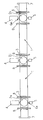
- the installation's heat treatment line includes two tubular sections 1 with round cross section, aligned and separated from each other by an intermediate connecting section 2i of same section and constituting a housing for a shaped electrode thick circular disc with rounded edges, of corresponding diameter, referenced in 3.
- the material constituting the sections and sections of the pipe is an electrically insulating material having good mechanical temperature resistance, such as for example polypropylene usable up to temperatures of around 100 ° C, or PEEK usable up to 200 to 250 ° C.
- In 4 we have schematized a jack or other clean motor to make pivot the electrode on command around its vertical diametrical axis, to bring it either in the open position shown in the figure, for which the electrode disc 3 is parallel to the axis of the pipe and allows the passage of products, either in a closed position to which the electrode 3 is brought into a position perpendicular to this axis and completely closes the pipe.
- In 5 we also represented schematically an electrical connection terminal to ensure the electrical connection between electrode 3 and a power source alternating current, not shown. The crossings of the wall of the driven by these mechanical and electrical connections are ensured by 6m and 6th watertight passages of all known types.
- the sections 1 are connected to two other exactly similar sections and serving as housings with similar electrodes and connected in the same way than in the intermediate section; it is a 2nd entry section and a outlet section 2s, themselves connected to short steel pipes stainless steel fitted with standard metal fittings 7. Connections between sections 1 and sections on the one hand, between extreme sections 2e, 2i and connections 7 on the other hand, are provided by flanges 8.
- the terminal 5 central unit is connected to a phase of the alternating current network single phase through an isolation transformer so avoid any current loopback with the distribution network, and the terminals 5 ends are connected to the other phase as well as to earth.
- a torus of measurement can be inserted in this link in order to control the current of leak and to be able to cut off the power supply if a threshold is exceeded predetermined, this for safety.
- the whole installation is fixed horizontally on a base of insulating material, and a cover (also not shown) covers the entire work area to avoid contact of operators with live parts during operation.
- a new cycle identical to the previous one can then be performed.
- the geometric and electrical characteristics of the installation will be determined from a specification specifying the initial and final temperatures of the product, its electrical conductivities at these temperatures as well as the hourly flow rate of the product, number of hourly operations. or heating time.
- the dimensions will be calculated taking into account in particular the maximum voltage applicable on the electrodes and the admissible current density on their surface which, with certain materials, may be of the order of 2500 A / m 2 continuously, with a frequency of 50 Hz.
- the material of the electrodes will be chosen according to the nature of the product treated, the current density and its frequency. There should not be in principle have neither corrosion nor electrochemical reaction with the product. Such materials are proposed in French patent n ° 98 03 154 at name of the applicant.
- the present invention has the advantage of allowing the heating of very viscous and heat-sensitive products, and to eliminate a large number disadvantages of conventional installations, whatever the viscosity of the product. There is no risk of overheating, in the absence of a hot wall, and the heating of the product has excellent homogeneity and can be relatively fast, even with reduced electrical energy involved. It should be noted that the products should preferably have a conductivity less than 20 S / m.
Landscapes
- Control Of Resistance Heating (AREA)
- Resistance Heating (AREA)
Abstract
Description
- commande de la rotation des électrodes 3 pour les amener dans une position d'ouverture parallèle à l'axe de la conduite de traitement ;
- introduction, par l'extrémité d'entrée de la conduite, du produit à traiter grâce à un système de pompage et éventuellement à un gaveur en cas de produit extrêmement visqueux ;
- commande de la rotation des électrodes 3 pour les amener clans une position de fermeture perpendiculaire à l'axe de la conduite, déterminant ainsi deux sections de chauffage identiques ;
- mise en tension des électrodes pendant le temps nécessaire à la montée en température jusqu'à la valeur choisie, puis coupure de l'alimentation, éventuellement après un palier de maintien en température ;
- rotation en sens inverse des électrodes pour les ramener en position d'ouverture ; et
- remise en marche du système de pompage, le produit arrivant dans la conduite chassant le produit traité qui en est ainsi évacué.
Claims (8)
- Installation de chauffage de produits, notamment visqueux, comprenant au moins une conduite chauffante pour l'écoulement desdits produits, caractérisée en ce que cette conduite comporte au moins une section tubulaire (1) en matériau électriquement isolant dont les deux extrémités peuvent être obturées chacune par une électrode (3), les deux électrodes (3) étant reliées à une source d'alimentation en courant électrique, et des volumes du produit à chauffer étant amenés séquentiellement entre les électrodes (3) pour y séjourner pendant un temps de chauffage ohmique déterminé, le courant passant entre les électrodes en traversant dans toute sa section le volume de produit introduit et immobilisé entre elles, ensuite de quoi le volume du produit traité est évacué de ladite conduite.
- Installation selon la revendication 1, caractérisée en ce que la section tubulaire est ronde et en ce que les électrodes (3), en forme de disques circulaires de diamètre correspondant, sont montées à demeure à ses deux extrémités en étant mobiles en rotation autour d'un axe diamétral, et ceci entre deux positions : une position d'ouverture parallèle à l'axe de la conduite, pour laquelle les électrodes (3) libèrent le passage et permettent l'introduction du volume de produit dans la section (1) avant chauffage ainsi que son évacuation après chauffage, et une position de fermeture perpendiculaire à cet axe de la conduite, pour laquelle cette section (1) est obturée, pendant l'opération de chauffage.
- Installation selon la revendication 2, caractérisée en ce que chaque électrode (3) est reliée d'une part mécaniquement à un axe moteur propre à la faire pivoter entre ses positions d'ouverture et de fermeture, et d'autre part électriquement à la source d'alimentation électrique par électrique étant assurées par des passages étanches (6m, 6e) de traversée de la paroi de la conduite.
- Installation selon l'une quelconque des revendications précédentes, caractérisée en ce que la conduite est constituée de plusieurs sections tubulaires alignées ( 1 ) de sorte à constituer un passage continu et lisse, deux sections voisines étant séparées par un tronçon de liaison (2i) tubulaire en matériau électriquement isolant et constituant un logement pour une électrode (3) intermédiaire, lequel tronçon de liaison (2i) est relié aux deux sections voisines (1) par des brides de fixation (8), des tronçons (2e, 2s) constituant logements à électrode du même type étant prévus aux deux extrémités de ladite conduite et étant reliés par des brides (8) à des tuyauteries à raccords métalliques (7), respectivement d'entrée et de sortie.
- Installation selon la revendication 4, caractérisée en ce que la conduite est constituée de deux sections (1) successives et comporte par suite trois électrodes (3) disposées respectivement dans trois tronçons de liaison (2e, 2i, 2s), l'électrode (3) intermédiaire étant raccordée à une phase d'une source de courant alternatif monophasé par l'intermédiaire d'un transformateur d'isolement, et les électrodes (3) d'extrémité étant reliées à l'autre phase ainsi qu'à la terre.
- Installation selon la revendication 4, caractérisée en ce que la conduite est constituée de trois sections successives et comporte par suite quatre électrodes disposées respectivement dans quatre tronçons de liaison, les électrodes intermédiaires étant raccordées aux phases d'une source de courant alternatif triphasé par l'intermédiaire d'un transformateur d'isolement, et les électrodes d'extrémité étant reliées à la terre.
- Installation selon l'une quelconque des revendications précédentes, caractérisée en ce qu'elle comporte plusieurs conduites alimentées en volumes de produit en parallèle mais ayant des cycles de chauffage décalés, de sorte qu'une conduite est en phase d'alimentation ou d'évacuation en produit tandis qu'une autre conduite est en phase de chauffage.
- Installation selon l'une quelconque des revendications précédentes, caractérisée en ce que lesdites conduites sont constituées de polypropylène, de PEEK, de céramique, de verre ou d'un composite en résine imprégnée de fibres de verre ou analogues.
Priority Applications (3)
| Application Number | Priority Date | Filing Date | Title |
|---|---|---|---|
| ES02291336T ES2267956T3 (es) | 2002-05-31 | 2002-05-31 | Instalacion de calentamiento de productos, en particular viscosos. |
| EP20020291336 EP1367858B1 (fr) | 2002-05-31 | 2002-05-31 | Installation de chauffage de produits, notamment visqueux |
| DE2002613073 DE60213073T2 (de) | 2002-05-31 | 2002-05-31 | Heizeinrichtung für Produckte, insbesondere pastöse Produkte |
Applications Claiming Priority (1)
| Application Number | Priority Date | Filing Date | Title |
|---|---|---|---|
| EP20020291336 EP1367858B1 (fr) | 2002-05-31 | 2002-05-31 | Installation de chauffage de produits, notamment visqueux |
Publications (2)
| Publication Number | Publication Date |
|---|---|
| EP1367858A1 true EP1367858A1 (fr) | 2003-12-03 |
| EP1367858B1 EP1367858B1 (fr) | 2006-07-12 |
Family
ID=29414835
Family Applications (1)
| Application Number | Title | Priority Date | Filing Date |
|---|---|---|---|
| EP20020291336 Expired - Lifetime EP1367858B1 (fr) | 2002-05-31 | 2002-05-31 | Installation de chauffage de produits, notamment visqueux |
Country Status (3)
| Country | Link |
|---|---|
| EP (1) | EP1367858B1 (fr) |
| DE (1) | DE60213073T2 (fr) |
| ES (1) | ES2267956T3 (fr) |
Cited By (1)
| Publication number | Priority date | Publication date | Assignee | Title |
|---|---|---|---|---|
| ITVR20120148A1 (it) * | 2012-07-17 | 2014-01-18 | Sanovo Technology Italia S R L | Impianto di riscaldamento ohmico per fluidi elettricamente conduttivi |
Citations (3)
| Publication number | Priority date | Publication date | Assignee | Title |
|---|---|---|---|---|
| WO1993004421A1 (fr) * | 1991-08-13 | 1993-03-04 | Sous Chef Limited | Regulation de temperature dans un procede ohmique |
| FR2741228A1 (fr) * | 1995-11-15 | 1997-05-16 | Electricite De France | Appareil de chauffage ohmique d'un liquide |
| FR2818085A1 (fr) * | 2000-12-08 | 2002-06-14 | Electricite De France | Installation de chauffage de produits, notamment visqueux |
-
2002
- 2002-05-31 ES ES02291336T patent/ES2267956T3/es not_active Expired - Lifetime
- 2002-05-31 DE DE2002613073 patent/DE60213073T2/de not_active Expired - Lifetime
- 2002-05-31 EP EP20020291336 patent/EP1367858B1/fr not_active Expired - Lifetime
Patent Citations (3)
| Publication number | Priority date | Publication date | Assignee | Title |
|---|---|---|---|---|
| WO1993004421A1 (fr) * | 1991-08-13 | 1993-03-04 | Sous Chef Limited | Regulation de temperature dans un procede ohmique |
| FR2741228A1 (fr) * | 1995-11-15 | 1997-05-16 | Electricite De France | Appareil de chauffage ohmique d'un liquide |
| FR2818085A1 (fr) * | 2000-12-08 | 2002-06-14 | Electricite De France | Installation de chauffage de produits, notamment visqueux |
Cited By (1)
| Publication number | Priority date | Publication date | Assignee | Title |
|---|---|---|---|---|
| ITVR20120148A1 (it) * | 2012-07-17 | 2014-01-18 | Sanovo Technology Italia S R L | Impianto di riscaldamento ohmico per fluidi elettricamente conduttivi |
Also Published As
| Publication number | Publication date |
|---|---|
| ES2267956T3 (es) | 2007-03-16 |
| DE60213073T2 (de) | 2007-02-08 |
| EP1367858B1 (fr) | 2006-07-12 |
| DE60213073D1 (de) | 2006-08-24 |
Similar Documents
| Publication | Publication Date | Title |
|---|---|---|
| EP1051880B1 (fr) | Vis transporteuse chauffante | |
| CA2882125C (fr) | Dispositif de traitement thermique d'un produit | |
| FR2778815A1 (fr) | Dispositif de chauffage magnetique | |
| EP0476311B1 (fr) | Dispositif pour le chauffage de fluides par effet joule | |
| FR2985654A1 (fr) | Radiateur seche-serviettes dont au moins un barreau porte-serviette integre un dissipateur thermique dans lequel est loge un cordon electrique chauffant | |
| FR2818085A1 (fr) | Installation de chauffage de produits, notamment visqueux | |
| EP0332505B1 (fr) | Four à micro-ondes | |
| EP1367858B1 (fr) | Installation de chauffage de produits, notamment visqueux | |
| WO2003103340A1 (fr) | Installation de chauffage de produits, notamment visqueux | |
| EP0418444B1 (fr) | Tambour sécheur, notamment pour machine de fabrication de papier | |
| FR2614490A1 (fr) | Applicateur micro-ondes pour traitement thermique de produits en grain, en poudre, en pate ou liquide | |
| FR2687514A1 (fr) | Dispositif-variateur de l'intensite du courant electrique dans un recepteur. | |
| WO2016046171A1 (fr) | Dispositif de traitement thermique d'un fluide a consommation energetique reduite | |
| FR2461425A1 (fr) | Dispositif de chauffage electrique, en continu, d'un produit liquide ou pateux electriquement conducteur, notamment du beton | |
| FR2485860A2 (fr) | Dispositif de chauffage electrique, en continu, d'un produit liquide ou pateux electriquement conducteur, notamment du beton | |
| FR2863829A1 (fr) | Procede de traitement thermique continu de fluide et dispositif pour la mise en oeuvre de ce procede | |
| FR2528224A1 (fr) | Transformateur, notamment abaisseur de tension pour machine a souder electrique | |
| FR2593014A1 (fr) | Cables electriques et preformes pour realiser ces cables | |
| OA11486A (fr) | Procédé et dispositif d fabrication d'une pluralité de thermocouples, et convertisseur thermoélectrique ainsi obtenu. | |
| FR2722053A1 (fr) | Dispositif et procede de chauffage d'un liquide ionique en ecoulement | |
| FR2787680A1 (fr) | Appareil de cuisson et procede mettant en oeuvre un tel appareil | |
| EP0081445B1 (fr) | Procédé de fabrication d'une bague collectrice pour appareil électrique du type tournant | |
| FR2851117A1 (fr) | Four pour la cuisson d'aliments | |
| FR2901449A1 (fr) | Cable chauffant auto-regulant | |
| FR2741228A1 (fr) | Appareil de chauffage ohmique d'un liquide |
Legal Events
| Date | Code | Title | Description |
|---|---|---|---|
| PUAI | Public reference made under article 153(3) epc to a published international application that has entered the european phase |
Free format text: ORIGINAL CODE: 0009012 |
|
| AK | Designated contracting states |
Kind code of ref document: A1 Designated state(s): AT BE CH CY DE DK ES FI FR GB GR IE IT LI LU MC NL PT SE TR |
|
| AX | Request for extension of the european patent |
Extension state: AL LT LV MK RO SI |
|
| 17P | Request for examination filed |
Effective date: 20040519 |
|
| AKX | Designation fees paid |
Designated state(s): DE ES GB IT |
|
| AXX | Extension fees paid |
Extension state: RO Payment date: 20040519 |
|
| 17Q | First examination report despatched |
Effective date: 20040727 |
|
| RAP1 | Party data changed (applicant data changed or rights of an application transferred) |
Owner name: ELECTRICITE DE FRANCE |
|
| GRAP | Despatch of communication of intention to grant a patent |
Free format text: ORIGINAL CODE: EPIDOSNIGR1 |
|
| GRAS | Grant fee paid |
Free format text: ORIGINAL CODE: EPIDOSNIGR3 |
|
| GRAA | (expected) grant |
Free format text: ORIGINAL CODE: 0009210 |
|
| AK | Designated contracting states |
Kind code of ref document: B1 Designated state(s): DE ES GB IT |
|
| AX | Request for extension of the european patent |
Extension state: RO |
|
| PG25 | Lapsed in a contracting state [announced via postgrant information from national office to epo] |
Ref country code: IT Free format text: LAPSE BECAUSE OF FAILURE TO SUBMIT A TRANSLATION OF THE DESCRIPTION OR TO PAY THE FEE WITHIN THE PRESCRIBED TIME-LIMIT;WARNING: LAPSES OF ITALIAN PATENTS WITH EFFECTIVE DATE BEFORE 2007 MAY HAVE OCCURRED AT ANY TIME BEFORE 2007. THE CORRECT EFFECTIVE DATE MAY BE DIFFERENT FROM THE ONE RECORDED. Effective date: 20060712 |
|
| REG | Reference to a national code |
Ref country code: GB Ref legal event code: FG4D Free format text: NOT ENGLISH |
|
| REF | Corresponds to: |
Ref document number: 60213073 Country of ref document: DE Date of ref document: 20060824 Kind code of ref document: P |
|
| GBT | Gb: translation of ep patent filed (gb section 77(6)(a)/1977) |
Effective date: 20061012 |
|
| REG | Reference to a national code |
Ref country code: ES Ref legal event code: FG2A Ref document number: 2267956 Country of ref document: ES Kind code of ref document: T3 |
|
| PLBE | No opposition filed within time limit |
Free format text: ORIGINAL CODE: 0009261 |
|
| STAA | Information on the status of an ep patent application or granted ep patent |
Free format text: STATUS: NO OPPOSITION FILED WITHIN TIME LIMIT |
|
| 26N | No opposition filed |
Effective date: 20070413 |
|
| PGFP | Annual fee paid to national office [announced via postgrant information from national office to epo] |
Ref country code: ES Payment date: 20110525 Year of fee payment: 10 |
|
| PGFP | Annual fee paid to national office [announced via postgrant information from national office to epo] |
Ref country code: GB Payment date: 20110426 Year of fee payment: 10 |
|
| PGFP | Annual fee paid to national office [announced via postgrant information from national office to epo] |
Ref country code: DE Payment date: 20110511 Year of fee payment: 10 Ref country code: IT Payment date: 20110530 Year of fee payment: 10 |
|
| GBPC | Gb: european patent ceased through non-payment of renewal fee |
Effective date: 20120531 |
|
| PG25 | Lapsed in a contracting state [announced via postgrant information from national office to epo] |
Ref country code: IT Free format text: LAPSE BECAUSE OF NON-PAYMENT OF DUE FEES Effective date: 20120531 |
|
| REG | Reference to a national code |
Ref country code: DE Ref legal event code: R119 Ref document number: 60213073 Country of ref document: DE Effective date: 20121201 |
|
| PG25 | Lapsed in a contracting state [announced via postgrant information from national office to epo] |
Ref country code: GB Free format text: LAPSE BECAUSE OF NON-PAYMENT OF DUE FEES Effective date: 20120531 |
|
| PG25 | Lapsed in a contracting state [announced via postgrant information from national office to epo] |
Ref country code: DE Free format text: LAPSE BECAUSE OF NON-PAYMENT OF DUE FEES Effective date: 20121201 |
|
| REG | Reference to a national code |
Ref country code: ES Ref legal event code: FD2A Effective date: 20130820 |
|
| PG25 | Lapsed in a contracting state [announced via postgrant information from national office to epo] |
Ref country code: ES Free format text: LAPSE BECAUSE OF NON-PAYMENT OF DUE FEES Effective date: 20120601 |