EP1367759A1 - Method and system for interference suppression in a TDMA and/or FDMA transmission - Google Patents
Method and system for interference suppression in a TDMA and/or FDMA transmission Download PDFInfo
- Publication number
- EP1367759A1 EP1367759A1 EP03019288A EP03019288A EP1367759A1 EP 1367759 A1 EP1367759 A1 EP 1367759A1 EP 03019288 A EP03019288 A EP 03019288A EP 03019288 A EP03019288 A EP 03019288A EP 1367759 A1 EP1367759 A1 EP 1367759A1
- Authority
- EP
- European Patent Office
- Prior art keywords
- projections
- filter
- output signal
- signal
- projection
- Prior art date
- Legal status (The legal status is an assumption and is not a legal conclusion. Google has not performed a legal analysis and makes no representation as to the accuracy of the status listed.)
- Granted
Links
Images


Classifications
-
- H—ELECTRICITY
- H04—ELECTRIC COMMUNICATION TECHNIQUE
- H04L—TRANSMISSION OF DIGITAL INFORMATION, e.g. TELEGRAPHIC COMMUNICATION
- H04L27/00—Modulated-carrier systems
-
- H—ELECTRICITY
- H04—ELECTRIC COMMUNICATION TECHNIQUE
- H04L—TRANSMISSION OF DIGITAL INFORMATION, e.g. TELEGRAPHIC COMMUNICATION
- H04L5/00—Arrangements affording multiple use of the transmission path
- H04L5/22—Arrangements affording multiple use of the transmission path using time-division multiplexing
- H04L5/26—Arrangements affording multiple use of the transmission path using time-division multiplexing combined with the use of different frequencies
-
- H—ELECTRICITY
- H04—ELECTRIC COMMUNICATION TECHNIQUE
- H04B—TRANSMISSION
- H04B7/00—Radio transmission systems, i.e. using radiation field
- H04B7/02—Diversity systems; Multi-antenna system, i.e. transmission or reception using multiple antennas
- H04B7/04—Diversity systems; Multi-antenna system, i.e. transmission or reception using multiple antennas using two or more spaced independent antennas
- H04B7/08—Diversity systems; Multi-antenna system, i.e. transmission or reception using multiple antennas using two or more spaced independent antennas at the receiving station
- H04B7/0837—Diversity systems; Multi-antenna system, i.e. transmission or reception using multiple antennas using two or more spaced independent antennas at the receiving station using pre-detection combining
- H04B7/0842—Weighted combining
- H04B7/0845—Weighted combining per branch equalization, e.g. by an FIR-filter or RAKE receiver per antenna branch
-
- H—ELECTRICITY
- H04—ELECTRIC COMMUNICATION TECHNIQUE
- H04L—TRANSMISSION OF DIGITAL INFORMATION, e.g. TELEGRAPHIC COMMUNICATION
- H04L1/00—Arrangements for detecting or preventing errors in the information received
- H04L1/02—Arrangements for detecting or preventing errors in the information received by diversity reception
- H04L1/06—Arrangements for detecting or preventing errors in the information received by diversity reception using space diversity
-
- H—ELECTRICITY
- H04—ELECTRIC COMMUNICATION TECHNIQUE
- H04L—TRANSMISSION OF DIGITAL INFORMATION, e.g. TELEGRAPHIC COMMUNICATION
- H04L25/00—Baseband systems
- H04L25/02—Details ; arrangements for supplying electrical power along data transmission lines
- H04L25/03—Shaping networks in transmitter or receiver, e.g. adaptive shaping networks
- H04L25/03006—Arrangements for removing intersymbol interference
- H04L25/03012—Arrangements for removing intersymbol interference operating in the time domain
- H04L25/03019—Arrangements for removing intersymbol interference operating in the time domain adaptive, i.e. capable of adjustment during data reception
- H04L25/03057—Arrangements for removing intersymbol interference operating in the time domain adaptive, i.e. capable of adjustment during data reception with a recursive structure
-
- H—ELECTRICITY
- H04—ELECTRIC COMMUNICATION TECHNIQUE
- H04L—TRANSMISSION OF DIGITAL INFORMATION, e.g. TELEGRAPHIC COMMUNICATION
- H04L25/00—Baseband systems
- H04L25/02—Details ; arrangements for supplying electrical power along data transmission lines
- H04L25/03—Shaping networks in transmitter or receiver, e.g. adaptive shaping networks
- H04L25/03993—Noise whitening
-
- H—ELECTRICITY
- H04—ELECTRIC COMMUNICATION TECHNIQUE
- H04L—TRANSMISSION OF DIGITAL INFORMATION, e.g. TELEGRAPHIC COMMUNICATION
- H04L25/00—Baseband systems
- H04L25/02—Details ; arrangements for supplying electrical power along data transmission lines
- H04L25/03—Shaping networks in transmitter or receiver, e.g. adaptive shaping networks
- H04L25/03006—Arrangements for removing intersymbol interference
- H04L2025/03433—Arrangements for removing intersymbol interference characterised by equaliser structure
- H04L2025/03439—Fixed structures
- H04L2025/03445—Time domain
- H04L2025/03471—Tapped delay lines
- H04L2025/03484—Tapped delay lines time-recursive
- H04L2025/0349—Tapped delay lines time-recursive as a feedback filter
Definitions
- the invention relates to methods for the digital transmission of data such as Example used in digital mobile radio systems or cable transmission systems become. It relates in particular to a method for suppressing interference for TDMA and / or FDMA transmission, which at least approximately by pulse amplitude modulation is writable with any number of receiving antennas, in which at least one complex-value received signal from a receiving antenna with a filter with complex-valued coefficients for generation at least an output signal is filtered.
- TDMA and FDMA designate the Access concepts time division multiple access and frequency division multiple Access.
- the invention also relates to a system for interference suppression for TDMA and / or FDMA transmission, which is at least approximately Pulse amplitude modulation can be described, comprising any number of Receiving antennas and at least one filter device with complex Coefficients for filtering at least one complex-value received signal Receiving antenna for generating at least one output signal.
- dispersive channels e.g. B. via a mobile radio channel or over two-wire lines
- the transmission signal is distorted and caused by noise disturbed.
- Special measures for recovery are therefore in the receiver the data sent from the received signal is necessary, i.e. an equalization process must be used.
- the best method for equalizing dispersive channels is the maximum likelihood sequence estimate Estimation, MLSE), described in G.D. Forney, Jr. "Maximum Likelihood Sequence Estimation of Digital Sequences in the Presence of Intersymbol Interference ", IEEE Transactions on Information Theory, IT-18, 363-378, May 1972, which by means of Viterbi algorithm can be performed.
- ACI adjacent channel Interference
- CCI co-channel interference
- the interference should be pre-processed be greatly reduced so that the remaining residual disorder as far as possible is small and white.
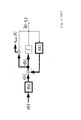
- a transmission with pulse amplitude modulation (PAM) via a distorting channel which generates intersymbol interference (ISI) can, as is known, be modeled in a time-discrete manner according to FIG. 1.
- the received signals sampled in the symbol clock 1 / T result from the folding of the PAM transmission sequence a [k] with the impulse response h i [k] of the channel belonging to the i-th antenna, the length of which is denoted by L i :
- the amplitude coefficients a [k] and the channel impulse responses h i [k] are either purely real, purely imaginary or complex; With regard to the invention, only modulation methods are considered below, the amplitude coefficients of which can be modeled in the receiver as purely real, purely imaginary or lying on any straight line in the complex plane.
- PAM signals can, for example, also approximately describe binary CPM (Continuous Phase Modulation) methods, as described in PA Laurent "Exact and approximate construction of digital phase modulations by superposition of amplitude modulated pulses (AMP)", IEEE Trans. On Commun. , COM 34, 150-160, 1986, which are often used in mobile communication because of their bandwidth efficiency and their low peak factor.
- n AWGN / i [k] represents interference by interference
- h INT / i. ⁇ [ ⁇ ] denotes the impulse response of the transmission from the ⁇ th interference interferer to the receiving antenna /
- L INT / i. ⁇ the corresponding impulse response length .
- the general case of / interference interference is considered, the data symbols of which are denoted by a INT / ⁇ [ ⁇ ] ; here too, only modulation methods with purely real, purely imaginary or amplitude coefficients which lie on any straight line in the complex plane are assumed with regard to the invention. Since the cases of purely imaginary amplitude coefficients or those lying on any straight line can be reduced to the case of real amplitude coefficients by a simple constant phase rotation, only this case will be considered in the following.
- the time-discrete reception signals of the different antennas can be represented by K poly-phase components present in the symbol clock 1 / T.
- the number of discrete-time received signals in the symbol clock thus increases to N-K.
- the further considerations can in principle also be applied to fractionally-spaced scanning.
- Two fundamentally different approaches are possible for the reconstruction of the transmitted symbols, cf. eg C. Tidestav, M. Sternad, A. Ahlen "Reuse Within a Cell - Interference Rejection or Multiuser Detection", IEEE Trans.
- the impulse responses h INT / i. ⁇ [ ⁇ ] are required for this, the estimation of which is very difficult because the receiver i. generally has no knowledge of the training sequences of the interference signals and the temporal position of the training sequences is also unknown to him, cf. e.g. BC Wah Lo, K. Ben Letaief "Adaptive Equalization and Interference Cancellation for Wireless Communication Systems", IEEE Trans. on Commun. COM-47, 538-545, April 1999.
- the resulting block diagram of the receiver is shown in Figure 1.
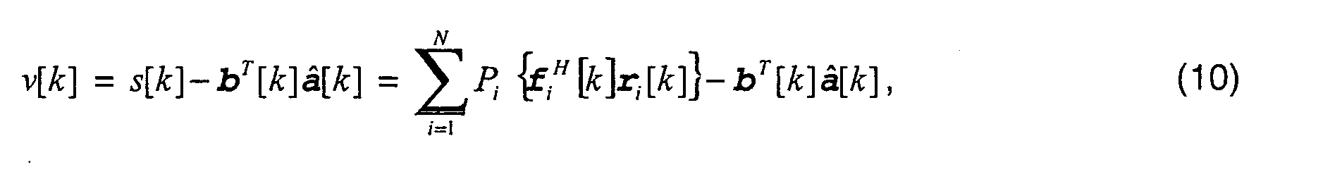
- the signal after feedforward filtering and combination is through given.
- the i-th filter for filtering the reception sequence r i [k] is shown in detail in FIG.
- the filter impulse responses f i [k] with lengths L ⁇ / i are optimized, for example, using an adaptive multiple-input-single-output minimum mean-squared error decision-feedback equalizer (MISO MMSE-DFE), the structure of which is shown in FIG , Thick lines symbolize complex values and thin lines represent real signals and systems.
- MISO MMSE-DFE adaptive multiple-input-single-output minimum mean-squared error decision-feedback equalizer
- Thick lines symbolize complex values and thin lines represent real signals and systems.
- the complex-valued impulse responses f i [k] play the role of feedforward filters in the DFE and are adaptive together with the complex-valued feedback filter b [k] to optimize.
- the filter coefficients of the feedforward filters are adopted for the structure according to FIG. 1. If the filter lengths are large enough, the interference is significantly reduced after the combination of the feedforward filter output signals; moreover, the overall disturbance at this point is approximately white and Gaussian, so that the subsequent use of a trellis-based equalization method is justified.
- No closed calculation method can be used for the pre-filter calculation, as suggested, for example, in EP 99 301 299.6 for the pre-filter of a DFSE / RSSE in the event of a fault, exclusively by white noise.
- the impulse responses of the interference signals h INT / i. ⁇ [ ⁇ ] b e would also be required, but these cannot be estimated in a simple manner, since the training sequences of the interference signals in the receiver i. are generally not known.
- the filter must therefore be calculated using a recursive adaptive algorithm. In S.
- EP 0 669 729 discloses antenna arrays for suppressing Use interference and noise.
- the reception signals of the individual Receiving antennas are combined into a vector that is different Is projected based on the spatial correlation matrix of the total interference consisting of interference and channel noise can be determined.
- the overall disturbance can thus be spatially decorrelated and a maximum ratio combining the pre-processed antenna signals to reduce interference is easier Way possible.
- the useful signal which is also from intersymbol interference is compromised using a conventional one-dimensional complex Equalization process regained.
- Those made in the process Projections are made on vectors whose number of dimensions N corresponds to the number of antennas N. A suppression of interference at only a single receiving antenna is not possible.
- FIG. 1 of EP 660 246 A2 shows the block diagram of a signal processor for a mobile radio device with a storage unit and a program storage unit.
- the object of the present invention is therefore that of the generic type Develop the method and the generic system such that an improved Interference suppression is made possible.
- According to another aspect of The invention is intended to enable good interference suppression even with mono reception become. Furthermore, it is desirable to have the capability to receive diversity compared to the previously proposed interference suppression methods to improve.
- a semiconductor device is also to be provided, to implement the method according to the invention or to implement the system according to the invention can be used.
- the invention is based on the knowledge that as a result of the projections Interference interference and the useful signal can be separated. Because only that Projections of the received signals can be processed, filter coefficients can be used Minimize the error in the sum of the projected signals, which is exclusive is of interest, can be found and used.
- the method and the system according to the invention permit (adaptive) interference suppression for equalization with or without antenna diversity when transmitted with pulse amplitude modulation with purely real-value, purely imaginary data sequences or on any straight line in the complex plane and sufficiently different impulse responses.
- significantly better interference suppression can be achieved than in the case of methods according to the prior art; with the inventive method i. generally 2N-1 interference signals are suppressed compared to only N-1 interference signals in the conventional method.
- the error rate of the subsequent equalization can be significantly reduced by the method according to the invention.
- the method usually causes no additional effort or even less effort in comparison to methods according to the prior art. Comparing, for example, FIG. 3 or 4 known from the prior art with the new structure according to FIG. 6 or 7, it is found that only projections P 1 ⁇ ⁇ to P n ⁇ have to be carried out in addition, while simplifying the feedback filter becomes purely real.
- step b there are at least two received signals r i [k] , the associated at least two output signals y i [k] being projected onto identical direction vectors in step b).
- This measure advantageously results in the projection and summation steps being interchangeable, the projections being able to be realized as a single projection after the summation.
- step a) feedforward filter of a DFE with real value Feedback filters are used that are systematically optimized, especially after the criteria ZF, MMSE or pulse shortening. This makes optimization possible the filter coefficients in a simple manner.
- the signals after the projections are preferred used. This will improve interference suppression allows for the interference in the sum of the orthogonal complements of the projections is shifted.
- any adaptive algorithm can be used. This ensures that an adaptation to the respective interference situation takes place automatically.
- the adaptive algorithm for setting the filter coefficients can be used by the receiver use known training sequence. If not, however, the recipient known training sequence is transmitted or this is too short can be provided a blind adaptive algorithm for setting the filter coefficients to use.
- a quality criterion for the transmission quality can be determined in a simple manner.
- At least a part can be in a first step the transmission signals interpreted as interference and with the invention Procedure can be suppressed. Then in a second step the data symbols detected in the first step to emulate the corresponding ones Receive signal components are used; the corresponding can be formed by forming the difference Remove signal components from the received signal with which a detection the remaining data symbols, interpreted as interference interference in the first step is made possible.
- the first can be repeated Step take place, with the data symbols detected in the first step now are assumed to be interference and in the first step the Interference interference assumed data symbols as useful symbols be interpreted.
- the method is therefore also suitable for achieving a high level Efficiency with antenna diversity on the transmission side.
- an improvement in interference suppression is achieved in that the DFE structure according to FIG. 3 or FIG. 4 is modified.
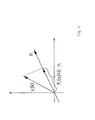
- projections P i ⁇ ⁇ are now made on complex vectors P i with length one, cf. Figure 5, which deliver purely real-valued results P i ⁇ y i [ ⁇ ] ⁇ .
- the error signal e [k] v [k] - a [kk 0 ] is also purely real.
- the orthogonal complements of the feedforward filter output signals with regard to the projection operators P i ⁇ ⁇ are therefore not considered any further, which is permissible since only one dimension of Interest is.
- the filter coefficients can now be set specifically to minimize the error in the sum of the projected signals, which is only of interest, while neglecting the orthogonal complements.
- interference interference can be largely shifted to the sum of the orthogonal complements of the projections of the feedforward filter output signals, which is irrelevant for decision making, by suitable choice of coefficients.
- the sum of the orthogonal complements can thus optionally be used to estimate the interference power.
- a special case of interest for implementation results when all N projection vectors of the output signals y i [k] are identical and the projections can thus be realized as a single projection after summation.
- the required complexity of the equalization method can optionally be controlled via the choice of the feedback filter length L b , that is to say the number of coefficients b [k] (pulse shortening with DFE).
- the DFE filter can be optimized according to various criteria, e.g. zero-forcing criterion, maximum SNR or minimum mean-squared error (MMSE).
- MMSE minimum mean-squared error
- the adaptive setting of the DFE according to the MMSE criterion using the least mean square (LMS) algorithm is considered as a special case. It should be noted for the adaptation that knowledge of the data symbols is required for error calculation in the algorithm and for feedback filtering.
- the training sequence transmitted in many transmission systems for channel estimation is also used for DFE adaptation, ie training symbols are used for error calculation and feedback filtering.
- the adaptation can be continued during the transmission of the data symbols with the aid of a decision, ie instead of training symbols, estimated data symbols supplied by the equalizer are then used, which after the training phase have a sufficiently high probability that they match the actual data symbols.
- the Recursive Least Squares (RLS) algorithm or a blind adaptation method can be used instead of the LMS algorithm, which only requires knowledge of the statistics of the data sequences, but not that of the data symbols themselves. In this case, however, a slower convergence than with trained adaptation methods has to be accepted.
- the decision delay k 0 is a degree of freedom that can be used to optimize performance efficiency.
- â [ ⁇ ] the data sequence decided by the DFE. If a known data sequence is available as a training sequence (training phase), the â [ ⁇ ] can be replaced by the known data symbols a [ ⁇ ]. Accordingly in Figure 6 â replace [ ⁇ ] for error calculation and feedback through a [ ⁇ ].
- the described DFE structure for interference suppression can also be used with additional M- fold (M ⁇ 1) antenna diversity on the transmission side, on which, for example, space-time-coded transmission for increasing the capacity is based, as in AF Naguib, N. Seshadri, and AR Calderbank " Increasing Data Rate over Wireless Channels ", IEEE Signal Processing Magazine, 76-92, May 2000.
- M ⁇ 1 M- fold
- the proposed method can be used directly in connection with the space-time-coded transmission method according to JH Winters "The Diversity Gain of Transmit Diversity in Wireless Systems with Rayleigh Fading", IEEE Transactions on Vehicular Technology, 119-123, February 1998.
- approximate PAM transmission methods are to be understood as methods whose transmission signal can be represented with sufficient accuracy by a PAM signal, for example binary continuous phase modulation (CPM).
- CPM binary continuous phase modulation
- the vector q i is orthogonal to the vector P i associated with the projection P i ⁇ .
- the signal t [k] contains i. generally a higher interference component than signal s [k], but also a useful component, ie Both the impulse response c [ ⁇ ], whose coefficients in the range ⁇ 1 ⁇ ⁇ 2 are not equal to zero, and the interference n t [k] consisting of noise and interference are purely real.
- the coefficients c [ K ] can be determined in a simple manner using a channel estimation method. After the channel has been estimated, the variance ⁇ 2 / nt of the disturbance n t [k] can be estimated.
- the signal t [k] in the trellis-based equalization.
- the signal s [k] according to Eq. (8) first in the form shown, the disturbance n s [k] having the variance ⁇ 2 n s and in turn including noise and interference.
- ⁇ [ ⁇ ] in the equalization method MLSE represent test symbols dependent on the state transitions
- ⁇ [kk 0 -K] also represent test symbols for K ⁇ K red and state-dependent path register contents for ⁇ > ⁇ red , where ⁇ red depends on the state reduction method selected.
- n t [ ⁇ ] has i. generally a certain color. It is therefore advisable to filter the signal t [k] before use in trellis-based equalization with a noise-whitening filter that converts n t [ ⁇ ] into a white disturbance and, based on the autocorrelation sequence of n t [ ⁇ ], which can be appropriately estimated can be determined.
- Eq. (21) is then ⁇ 2 / n to be replaced by the noise variance at the output of the noise whitening filter, t [k] by the signal at the output of the noise whitening filter, and c [ ⁇ ] by the convolution of the original Impulse response with the impulse response of the noise whitening filter.
Landscapes
- Engineering & Computer Science (AREA)
- Signal Processing (AREA)
- Computer Networks & Wireless Communication (AREA)
- Power Engineering (AREA)
- Cable Transmission Systems, Equalization Of Radio And Reduction Of Echo (AREA)
- Radio Transmission System (AREA)
- Noise Elimination (AREA)
- Radio Relay Systems (AREA)
- Near-Field Transmission Systems (AREA)
- Time-Division Multiplex Systems (AREA)
Abstract
Description
Die Erfindung betrifft Verfahren zur digitalen Übertragung von Daten wie sie zum Beispiel bei digitalen Mobilfunksystemen oder Kabelübertragungssystemen eingesetzt werden. Sie betrifft insbesondere ein Verfahren zur Interferenzunterdrückung für TDMA- und/oder FDMA-Übertragung, die zumindest näherungsweise durch Pulsamplitudenmodulation beschreibbar ist, mit einer beliebigen Anzahl an Empfangsantennen, bei der zumindest ein komplexwertiges Empfangssignal einer Empfangsantenne mit einem Filter mit komplexwertigen Koeffizienten zur Erzeugung zumindest eines Ausgangssignals gefiltert wird. TDMA und FDMA bezeichnen hierbei die Zugriffskonzepte Time-Division Multiple Access sowie Frequency-Division Multiple Access. Darüber hinaus betrifft die Erfindung ein System zur Interferenzunterdrückung für TDMA und/oder FDMA-Übertragung, die zumindest näherungsweise durch Pulsamplitudenmodulation beschreibbar ist, umfassend eine beliebige Anzahl an Empfangsantennen sowie mindestens eine Filtervorrichtung mit komplexwertigen Koeffizienten zur Filterung mindestens eines komplexwertigen Empfangssignals einer Empfangsantenne zur Erzeugung zumindest eines Ausgangssignals.The invention relates to methods for the digital transmission of data such as Example used in digital mobile radio systems or cable transmission systems become. It relates in particular to a method for suppressing interference for TDMA and / or FDMA transmission, which at least approximately by pulse amplitude modulation is writable with any number of receiving antennas, in which at least one complex-value received signal from a receiving antenna with a filter with complex-valued coefficients for generation at least an output signal is filtered. TDMA and FDMA designate the Access concepts time division multiple access and frequency division multiple Access. The invention also relates to a system for interference suppression for TDMA and / or FDMA transmission, which is at least approximately Pulse amplitude modulation can be described, comprising any number of Receiving antennas and at least one filter device with complex Coefficients for filtering at least one complex-value received signal Receiving antenna for generating at least one output signal.
Bei der digitalen Übertragung über dispersive Kanäle, z. B. über einen Mobilfunkkanal oder über Zweidrahtleitungen, wird das Sendesignal verzerrt und durch Rauschen gestört. Im Empfänger sind somit spezielle Maßnahmen zur Wiedergewinnung der gesendeten Daten aus dem Empfangssignal notwendig, d.h. ein Entzerrverfahren muß eingesetzt werden. Das optimale Verfahren zur Entzerrung dispersiver Kanäle ist die Maximum-Likelihood-Sequenzschätzung (Maximum-Likelihood Sequence Estimation, MLSE), beschrieben in G.D. Forney, Jr. "Maximum-Likelihood Sequence Estimation of Digital Sequences in the Presence of Intersymbol Interference", IEEE Transactions on Information Theory, IT-18, 363-378, May 1972, die mittels des Viterbi-Algorithmus durchgeführt werden kann. Allerdings kann der Viterbi-Algorithmus bei langen Kanalimpulsantworten und/oder nichtbinären Signalalphabeten wegen des dann sehr hohen Aufwandes in der Praxis nicht mehr realisiert werden. Somit müssen in diesen Fällen suboptimale Verfahren wie zustandsreduzierte Sequenzschätzung, z.B. in den Varianten Reduced-State Sequence Estimation (RSSE), beschrieben in M.V. Eyuboglu, S.U. Qureshi "Reduced-State Sequence Estimation with Set Partitioning and Decision Feedback", IEEE Trans. on Commun., COM-36, 13-20, January 1988, oder Decision-Feedback Sequence Estimation (DFSE), beschrieben in A. Duel-Hallen, C. Heegard "Delayed Decision-Feedback Sequence Estimation", IEEE Trans. on Commun., COM-37, 428-436, May 1989, verwendet werden.With digital transmission via dispersive channels, e.g. B. via a mobile radio channel or over two-wire lines, the transmission signal is distorted and caused by noise disturbed. Special measures for recovery are therefore in the receiver the data sent from the received signal is necessary, i.e. an equalization process must be used. The best method for equalizing dispersive channels is the maximum likelihood sequence estimate Estimation, MLSE), described in G.D. Forney, Jr. "Maximum Likelihood Sequence Estimation of Digital Sequences in the Presence of Intersymbol Interference ", IEEE Transactions on Information Theory, IT-18, 363-378, May 1972, which by means of Viterbi algorithm can be performed. However, the Viterbi algorithm can with long channel impulse responses and / or non-binary signal alphabets can no longer be realized in practice because of the then very high expenditure. Thus, in these cases, suboptimal procedures such as reduced-status Sequence estimation, e.g. in the variants Reduced-State Sequence Estimation (RSSE), described in M.V. Eyuboglu, S.U. Qureshi "Reduced-State Sequence Estimation with Set Partitioning and Decision Feedback ", IEEE Trans. On Commun., COM-36, 13-20, January 1988, or Decision-Feedback Sequence Estimation (DFSE), described in A. Duel-Hallen, C. Heegard "Delayed Decision-Feedback Sequence Estimation ", IEEE Trans. On Commun., COM-37, 428-436, May 1989, be used.
Die genannten Verfahren sind alle für den Fall optimiert, daß das Empfangssignal durch additives weißes Gaußsches Rauschen (additive white Gaussian noise, AWGN) gestört wird. Treten zusätzliche Störungen durch Interferenzen anderer übertragener Signale auf, so muß mit einer starken Degradation des Entzerrverfahrens aufgrund einer Metrikfehlanpassung und zu starker Varianz der Störung gerechnet werden. Interferenzstörungen spielen in Mobilfunksystemen und Kabelübertragungssystemen eine zunehmend bedeutende Rolle. Eine Degradation der Leistungseffizienz resultiert sowohl bei Nachbarkanalinterferenz (Adjacent Channel Interference, ACI) als auch bei Gleichkanalinterferenz (Cochannel Interference, CCI, d.h. Nutzund Störsignal belegen das gleiche Frequenzband), sofern keine zusätzlichen Maßnahmen getroffen werden. Vor der Entzerrung sollte die Interferenz durch eine Vorverarbeitung stark reduziert werden, so daß die verbleibende Reststörung möglichst gering und weiß ist. Da die spektrale Charakteristik der Interferenz bei einer blockweisen Übertragung meist von Block zu Block variiert, ist die Vorverarbeitung in jedem Block neu einzustellen. Eine geeignete Vorverarbeitungsstrategie wurde in S. Ariyavisitakul, J.H. Winters, N.R. Sollenberger "Joint Equalization and Interference Suppression for High Data Rate Wireless Systems", in Proceedings of Vehicular Technology Conference (VTC'99 Spring), S. 700-706, Houston, Texas, 1999 angegeben. Mit dieser Strategie kann allerdings nur bei Diversity-Empfang eine gute Leistungsfähigkeit erreicht werden, d.h. es müssen mindestens zwei Empfangsantennen vorliegen. Die darin beschriebene Lehre wurde zur Formulierung des Oberbegriffs der unabhängigen Ansprüche verwendet.The methods mentioned are all optimized for the case that the received signal due to additive white Gaussian noise (additive white Gaussian noise, AWGN) is disturbed. Additional interference occurs due to interference from other transmitted Signals on, must with a strong degradation of the equalization process due to metric mismatch and excessive variance of the disorder become. Interference interference play in mobile radio systems and cable transmission systems an increasingly important role. A degradation in performance efficiency results in both adjacent channel interference (Adjacent Channel Interference, ACI) as well as with co-channel interference (CCI, i.e. useful and Interference signal occupy the same frequency band), unless additional measures are taken to be hit. Before the equalization, the interference should be pre-processed be greatly reduced so that the remaining residual disorder as far as possible is small and white. Because the spectral characteristics of the interference in a block Transfer varies mostly from block to block, preprocessing is in everyone Readjust block. A suitable preprocessing strategy was described in S. Ariyavisitakul, J.H. Winters, N.R. Sollenberger "Joint Equalization and Interference Suppression for High Data Rate Wireless Systems ", in Proceedings of Vehicular Technology Conference (VTC'99 Spring), pp. 700-706, Houston, Texas, 1999. With this strategy, however, good performance is only possible with diversity reception be achieved, i.e. there must be at least two receiving antennas available. The teaching described therein became the formulation of the generic term of independent claims used.
Eine Übertragung mit Pulsamplitudenmodulation (PAM) über einen verzerrenden
Kanal, der Intersymbolinterferenzen (ISI) erzeugt, kann bekanntlich zeitdiskret gemäß
Figur 1 modelliert werden. Es wird der allgemeine Fall von N-facher Antennendiversität
(N≥ 1) im Empfänger angenommen; als Spezialfall (N=1) ergibt sich der
Mono-Empfang. Die im Symboltakt 1/T abgetasteten Empfangssignale ergeben
sich als durch Störung beeinträchtigte Faltung der PAM-Sendesequenz a[k] mit der
Impulsantwort hi [k] des zur i-ten Antenne gehörigen Kanals, deren Länge mit Li bezeichnet
wird:

Je nach verwendetem Modulationsverfahren sind die Amplitudenkoeffizienten a[k]
und die Kanalimpulsantworten hi[k] entweder rein reell, rein imaginär oder komplex;
im Hinblick auf die Erfindung werden nachfolgend ausschließlich Modulationsverfahren
betrachtet, deren Amplitudenkoeffizienten im Empfänger als rein reell, rein imaginär
oder auf einer beliebigen Geraden in der komplexen Ebene liegend, modelliert
werden können. Durch PAM-Signale können z.B. auch binäre CPM- (Continuous
Phase Modulation) Verfahren näherungsweise beschrieben werden, wie in P.A. Laurent
"Exact and approximate construction of digital phase modulations by superposition
of amplitude modulated pulses (AMP)", IEEE Trans. on Commun., COM 34, 150-160,
1986 beschrieben, die aufgrund ihrer Bandbreiteneffizienz und ihres geringen
Spitzenwertfaktors oft in der Mobilkommunikation eingesetzt werden. Die zeitdiskrete
Störung ni [k] besteht aus zwei Komponenten,

Für eine Fractionally-Spaced-Abtastung mit Abtasttakt K/T(K : Überabtastfaktor, z.B.
K=2) der zeitkontinuierlichen Empfangssignale der verschiedenen Antennen resultiert
prinzipiell dasselbe Modell. In diesem Fall können die zeitdiskreten Empfangssignale
der verschiedenen Antennen durch jeweils K im Symboltakt 1/T vorliegende Polyphasenkomponenten
repräsentiert werden. Insgesamt erhöht sich die Anzahl der
zeitdiskreten Empfangssignale im Symboltakt also auf N- K. Somit sind die weiteren
Betrachtungen prinzipiell auch auf Fractionally-Spaced-Abtastung anwendbar. Zur
Rekonstruktion der gesendeten Symbole sind zwei prinzipiell verschiedene Ansätze
möglich, vgl. z.B C. Tidestav, M. Sternad, A. Ahlen "Reuse Within a Cell - Interference
Rejection or Multiuser Detection", IEEE Trans. on Commun., COM-47, 1511-1522,
October 1999. So können zum einen Prinzipien der Multiuser-Detektion angewendet
werden, d.h. die Symbolfolgen a[· ] und a INT / µ[·], µ∈ {1,2,...,I} werden gemeinsam geschätzt
(Joint Maximum--Likelihood Sequence Estimation). In den Ausdrücken für die
Symbolfolgen symbolisiert der Punkt [· ] die komplette Symbolfolge a[k], mit -∞ < k <
+∞. Mit diesem Ansatz kann eine optimale Schätzgüte erreicht werden.
Allerdings ist der benötigte Rechenaufwand bei einer gemeinsamen (bzw. iterativen)
Schätzung sehr hoch. Zudem werden hierfür die Impulsantworten h INT / i.µ[κ] benötigt,
deren Schätzung sich als sehr schwierig gestaltet, da der Empfänger i. allg. keine
Kenntnis der Trainingssequenzen der Interferenzsignale besitzt und ihm die zeitliche
Position der Trainingssequenzen ebenfalls unbekannt ist, vgl. z.B. B.C. Wah Lo, K.
Ben Letaief "Adaptive Equalization and Interference Cancellation for Wireless Communication
Systems", IEEE Trans. on Commun. COM-47, 538-545, April 1999.In principle, the same model results for a fractionally-spaced sampling with sampling clock K / T (K: oversampling factor, for example K = 2) of the continuous-time received signals of the different antennas. In this case, the time-discrete reception signals of the different antennas can be represented by K poly-phase components present in the
Aus diesen Gründen erweist sich der zweite Ansatz als vielversprechender, bei dem
zuerst eine Interferenzunterdrückung und anschließend eine Entzerrung durchgeführt
wird. Ein auf diesem Ansatz basierendes Verfahren wurde in S. Ariyavisitakul, J.H.
Winters, N.R. Sollenberger "Joint Equalization and Interference Suppression for High
Data Rate Wireless Systems", in Proceedings of Vehicular Technology Conference
(VTC'99 Spring), S. 700-706, Houston, Texas, 1999, vorgeschlagen. Dabei werden
die N verschiedenen zeitdiskreten Empfangssignale yi [k] separat vorgefiltert und
dann die Ausgangssignale der Vorfilter, vgl. Figur 1, kombiniert. Anschließend erfolgt
eine Entzerrung, z.B. eine MLSE, RSSE, DFSE oder DFE (Decision-Feedback Equalization).
Das resultierende Blockschaltbild des Empfängers ist in Figur 1 dargestellt.
Das Signal nach Feedforward-Filterung und Kombination ist durch

Zur Vorfilterberechnung kann kein geschlossenes Berechnungsverfahren, wie z.B. in EP 99 301 299.6 für das Vorfilter einer DFSE/RSSE bei Störung ausschließlich durch weißes Rauschen vorgeschlagen, angewendet werden. Hierzu würden neben den Impulsantworten hi [k] auch die Impulsantworten der Interferenzsignale h INT / i.µ[κ] benötigt werden, die jedoch nicht in einfacher Weise geschätzt werden können, da die Trainingssequenzen der Interferenzsignale im Empfänger i. allg. nicht bekannt sind. Somit muß die Filterberechnung über einen rekursiven adaptiven Algorithmus erfolgen. In S. Ariyavisitakul, J.H. Winters, N.R. Sollenberger "Joint Equalization and Interference Suppression for High Data Rate Wireless Systems", Proceedings of Vehicular Technology Conference (VTC'99 Spring), S. 700-706, Houston, Texas, 1999, wurde der Einsatz des Recursive-Least-Squares (RLS) Algorithmus, vgl. auch S. Haykin "Adaptive Filter Theory", Prentice Hall, Upper Saddle River, New Jersey, third edition, 1996, zur Filteroptimierung vorgeschlagen. Ein wesentlicher Nachteil der beschriebenen Vorgehensweise ist, daß damit für den Fall von Mono-Empfang (N=1) keine gute Leistungsfähigkeit erreicht werden kann. Der wesentliche Grund hierfür liegt darin, daß eine Interferenzstörung in diesem Fall nur unzureichend unterdrückt werden kann. Mit Bezug auf Figur 3 umfassen die Signale r1[k] und r2[k] für N=2 das jeweilige Empfangssignal sowie Rauschen, wobei im Rauschen die Interferenzsignale mitumfasst sind. Durch geeignete Einstellung der Filterkoeffizienten kann erreicht werden, daß sich die Interferenzsignale gegenseitig eliminieren. Bei N=1 und damit dem Vorliegen nur eines Empfangssignals ist dies naturgemäß nicht möglich. No closed calculation method can be used for the pre-filter calculation, as suggested, for example, in EP 99 301 299.6 for the pre-filter of a DFSE / RSSE in the event of a fault, exclusively by white noise. In addition to the impulse responses h i [k] , the impulse responses of the interference signals h INT / i.µ [κ] b e would also be required, but these cannot be estimated in a simple manner, since the training sequences of the interference signals in the receiver i. are generally not known. The filter must therefore be calculated using a recursive adaptive algorithm. In S. Ariyavisitakul, JH Winters, NR Sollenberger "Joint Equalization and Interference Suppression for High Data Rate Wireless Systems", Proceedings of Vehicular Technology Conference (VTC'99 Spring), pp. 700-706, Houston, Texas, 1999 Use of the recursive least squares (RLS) algorithm, cf. also S. Haykin "Adaptive Filter Theory", Prentice Hall, Upper Saddle River, New Jersey, third edition, 1996, proposed for filter optimization. A major disadvantage of the procedure described is that it cannot achieve good performance in the case of mono reception (N = 1) . The main reason for this is that in this case interference interference can only be insufficiently suppressed. With reference to FIG. 3, the signals r 1 [k] and r 2 [k] for N = 2 comprise the respective received signal and noise, the interference signals also being included in the noise. By suitable adjustment of the filter coefficients it can be achieved that the interference signals eliminate each other. With N = 1 and thus the presence of only one received signal, this is naturally not possible.
Aus der EP 0 669 729 ist bekannt, Antennenarrays zur Unterdrückung von
Interferenz- und Rauschstörungen zu verwenden. Die Empfangssignale der einzelnen
Empfangsantennen werden zu einem Vektor zusammengefasst der auf verschiedene
Vektoren projiziert wird, die anhand der räumlichen Korrelationsmatrix der
aus Interferenz und Kanalrauschen bestehenden Gesamtstörung bestimmt werden.
Damit kann die Gesamtstörung räumlich dekorreliert werden und ein maximum ratio
combining der vorverarbeiteten Antennensignale zur Störreduktion ist in einfacher
Weise möglich. Danach wird das Nutzsignal, das zusätzlich noch von Intersymbolinterferenzen
beeinträchtigt ist, mittels eines herkömmlichen eindimensionalen komplexen
Entzerrprozesses wiedergewonnen. Die in dem Verfahren vorgenommenen
Projektionen werden auf Vektoren vorgenommen, deren Anzahl von Dimensionen N
der Anzahl der Antennen N entspricht. Eine Unterdrückung von Interferenzen bei nur
einer einzigen Empfangsantenne ist nicht möglich.
Es ist einschlägig bekannt, derartige Verfahren und Algorithmen in einen Halbleiterbaustein abzulegen, der dann in einem Handy implementiert werden kann. Beispielhaft zeigt die Figur 1 der EP 660 246 A2 das Blockschaltbild eines Signalprozessors für ein Mobilfunkgerät mit einer Speichereinheit und einer Programmspeichereinheit.It is well known in the art to incorporate such methods and algorithms in a semiconductor device file, which can then be implemented in a cell phone. exemplary FIG. 1 of EP 660 246 A2 shows the block diagram of a signal processor for a mobile radio device with a storage unit and a program storage unit.
Die Aufgabe der vorliegenden Erfindung besteht deshalb darin, das gattungsgemäße Verfahren und das gattungsgemäße System derart weiterzubilden, daß eine verbesserte Interferenzunterdrückung ermöglicht wird. Gemäß einem weiteren Aspekt der Erfindung soll eine gute Interferenzunterdrückung auch bei Mono-Empfang ermöglicht werden. Weiterhin ist erwünscht, die Leistungsfähigkeit bei Diversity-Empfang gegenüber den bisher vorgeschlagenen Interferenzunterdrückungsverfahren weiter zu verbessern. Schließlich soll weiterhin ein Halbleiterbaustein bereitgestellt werden, der zur Durchführung des erfindungsgemäßen Verfahrens bzw. zur Realisierung des erfindungsgemäßen Systems eingesetzt werden kann.The object of the present invention is therefore that of the generic type Develop the method and the generic system such that an improved Interference suppression is made possible. According to another aspect of The invention is intended to enable good interference suppression even with mono reception become. Furthermore, it is desirable to have the capability to receive diversity compared to the previously proposed interference suppression methods to improve. Finally, a semiconductor device is also to be provided, to implement the method according to the invention or to implement the system according to the invention can be used.
Diese Aufgaben werden erfindungsgemäß gelöst durch ein Verfahren mit den Merkmalen
von Anspruch 1 sowie durch ein System mit den Merkmalen von Anspruch 10. According to the invention, these objects are achieved by a method having the features
of
Die Erfindung basiert auf der Erkenntnis, daß als Folge der Projektionen die Interferenzstörung und das Nutzsignal separiert werden können. Da nämlich nur die Projektionen der Empfangssignale verarbeitet werden, können Filterkoeffizienten zur Minimierung des Fehlers in der Summe der projizierten Signale, der ausschließlich von Interesse ist, gefunden und verwendet werden.The invention is based on the knowledge that as a result of the projections Interference interference and the useful signal can be separated. Because only that Projections of the received signals can be processed, filter coefficients can be used Minimize the error in the sum of the projected signals, which is exclusive is of interest, can be found and used.
Das erfindungsgemäße Verfahren und das erfindungsgemäße System erlauben eine (adaptive) Interferenzunterdrückung für eine Entzerrung mit bzw. ohne Antennendiversität bei Übertragung mit Pulsamplitudenmodulation mit rein reellwertigen, rein imaginären oder auf einer beliebigen Geraden in der komplexen Ebene liegenden Datensequenzen und hinreichend unterschiedlichen Impulsantworten. Insbesondere im Fall von Mono-Empfang kann eine deutlich bessere Interferenzunterdrückung als bei Verfahren nach dem Stand der Technik erreicht werden; mit dem erfindungsgemäßen Verfahren können i. allg. 2N-1 Interferenzsignale unterdrückt werden, im Vergleich zu nur N-1 Interferenzsignalen beim herkömmlichen Verfahren. Die Fehlerrate der nachfolgenden Entzerrung kann durch das erfindungsgemäße Verfahren deutlich reduziert werden.The method and the system according to the invention permit (adaptive) interference suppression for equalization with or without antenna diversity when transmitted with pulse amplitude modulation with purely real-value, purely imaginary data sequences or on any straight line in the complex plane and sufficiently different impulse responses. In the case of mono reception in particular, significantly better interference suppression can be achieved than in the case of methods according to the prior art; with the inventive method i. generally 2N-1 interference signals are suppressed compared to only N-1 interference signals in the conventional method. The error rate of the subsequent equalization can be significantly reduced by the method according to the invention.
Das Verfahren verursacht in einer praktischen Implementierung meist keinen Mehraufwand oder sogar einen geringeren Aufwand im Vergleich zu Verfahren nach dem Stand der Technik. Vergleicht man beispielsweise die aus dem Stand der Technik bekannte Figur 3 bzw. 4 mit der neuen Struktur nach Figur 6 bzw. 7, so zeigt sich, daß lediglich Projektionen P1{· } bis Pn {· } zusätzlich durchzuführen sind, wohingegen vereinfachend das Rückkopplungsfilter rein reell wird.In a practical implementation, the method usually causes no additional effort or even less effort in comparison to methods according to the prior art. Comparing, for example, FIG. 3 or 4 known from the prior art with the new structure according to FIG. 6 or 7, it is found that only projections P 1 {· } to P n {·} have to be carried out in addition, while simplifying the feedback filter becomes purely real.
Bei einer besonders bevorzugten Ausführungsform der Erfindung liegen mindestens zwei Empfangssignale ri[k] vor, wobei die zugehörigen mindestens zwei Ausgangssignale yi[k] in Schritt b) auf identische Richtungsvektoren projiziert werden. Diese Maßnahme resultiert in vorteilhafter Weise darin, daß Projektions- und Summationsschritt vertauscht werden können, wobei die Projektionen nach der Summation als eine einzige Projektion realisiert werden können. In a particularly preferred embodiment of the invention, there are at least two received signals r i [k] , the associated at least two output signals y i [k] being projected onto identical direction vectors in step b). This measure advantageously results in the projection and summation steps being interchangeable, the projections being able to be realized as a single projection after the summation.
Bei einer weiteren bevorzugten Ausführungsform werden für die Filterung der Empfangssignale in Schritt a) Feedforward-Filter einer DFE mit reellwertigem Feedback-Filter verwendet, die systematisch optimiert werden, insbesondere nach den Kriterien ZF, MMSE oder Impulsverkürzung. Dadurch wird es möglich eine Optimierung der Filterkoeffizienten in einfacher Weise vorzunehmen.In a further preferred embodiment, filtering the received signals in step a) feedforward filter of a DFE with real value Feedback filters are used that are systematically optimized, especially after the criteria ZF, MMSE or pulse shortening. This makes optimization possible the filter coefficients in a simple manner.
Zur Optimierung der Filterkoeffizienten werden bevorzugt die Signale nach den Projektionen herangezogen. Dadurch wird eine verbesserte Interferenzunterdrückung ermöglicht, da die Interferenz in die Summe der orthogonalen Komplemente der Projektionen verlagert wird.To optimize the filter coefficients, the signals after the projections are preferred used. This will improve interference suppression allows for the interference in the sum of the orthogonal complements of the projections is shifted.
Zur Einstellung der Filterkoeffizienten des mindestens einen komplexwertigen Filters kann ein beliebiger adaptiver Algorithmus verwendet werden. Hierdurch wird sichergestellt, daß eine Anpassung an die jeweilige Interferenzsituation automatisch erfolgt.For setting the filter coefficients of the at least one complex filter any adaptive algorithm can be used. This ensures that an adaptation to the respective interference situation takes place automatically.
Der adaptive Algorithmus zur Einstellung der Filterkoeffizienten kann eine dem Empfänger bekannte Trainingssequenz verwenden. Falls jedoch keine dem Empfänger bekannte Trainingssequenz übertragen wird oder diese zu kurz ist, kann vorgesehen werden, einen blinden adaptiven Algorithmus zur Einstellung der Filterkoeffizienten zu verwenden.The adaptive algorithm for setting the filter coefficients can be used by the receiver use known training sequence. If not, however, the recipient known training sequence is transmitted or this is too short can be provided a blind adaptive algorithm for setting the filter coefficients to use.
Durch Berechnung des orthogonalen Komplements der Projektion für mindestens ein gefiltertes Ausgangssignal yi [k] läßt sich in einfacher Weise ein Gütekriterium für die Übertragungsqualität ermitteln.By calculating the orthogonal complement of the projection for at least one filtered output signal y i [k], a quality criterion for the transmission quality can be determined in a simple manner.
Bei sendeseitiger Antennendiversität kann in einem ersten Schritt zumindest ein Teil der Sendesignale als Interferenzstörung interpretiert und mit dem erfindungsgemäßen Verfahren unterdrückt werden. Anschließend können in einem zweiten Schritt die im ersten Schritt detektierten Datensymbole zur Nachbildung der entsprechenden Empfangssignalanteile benutzt werden; durch Differenzbildung lassen sich die entsprechenden Signalanteile aus dem Empfangssignal entfernen womit eine Detektion der verbliebenen, im ersten Schritt als Interferenzstörung interpretierte Datensymbole ermöglicht wird. Alternativ dazu kann im zweiten Schritt eine Wiederholung des ersten Schrittes stattfinden, wobei nunmehr die im ersten Schritt detektierten Datensymbole als Interferenzstörung angenommen werden und die im ersten Schritt als Interferenzstörung angenommenen Datensymbole als Nutzsymbole interpretiert werden. Somit eignet sich das Verfahren auch zur Erzielung einer hohen Leistungsfähigkeit bei sendeseitiger Antennendiversität.In the case of transmitter-side antenna diversity, at least a part can be in a first step the transmission signals interpreted as interference and with the invention Procedure can be suppressed. Then in a second step the data symbols detected in the first step to emulate the corresponding ones Receive signal components are used; the corresponding can be formed by forming the difference Remove signal components from the received signal with which a detection the remaining data symbols, interpreted as interference interference in the first step is made possible. Alternatively, in the second step, the first can be repeated Step take place, with the data symbols detected in the first step now are assumed to be interference and in the first step the Interference interference assumed data symbols as useful symbols be interpreted. The method is therefore also suitable for achieving a high level Efficiency with antenna diversity on the transmission side.
Weitere vorteilhafte Ausführungsformen der Erfindung sind in den Unteransprüchen definiert. Im folgenden werden Ausführungsbeispiele der Erfindung unter Hinweis auf die beigefügten Zeichnungen näher beschrieben. Es zeigen:
- Figur 1:
- in zeitdiskreter Darstellung ein Blockschaltbild einer digitalen Übertragung mit N-facher Antennendiversität im Empfänger (Stand der Technik);
- Figur 2:
- eine detaillierte Darstellung des i-ten Feedforward-Filters zur Filterung des i-ten Empfangssignals (Stand der Technik);
- Figur 3:
- in Blockschaltbilddarstellung einen konventionellen DFE-Empfänger für den Fall von N Empfangsantennen (Stand der Technik);
- Figur 4:
- in Blockschaltbilddarstellung einen konventionellen DFE-Empfänger für den Fall von einer Empfangsantenne (Stand der Technik);
- Figur 5:
- in schematischer Darstellung die Projektion Pi{yi[k]} des Signals yi[k] auf einen komplexen Vektor p i mit Länge Eins;
- Figur 6:
- einen DFE-Empfänger für den Fall von N Empfangsantennen mit Durchführung von Projektionen nach den Feedforward-Filterungen gemäß der Erfindung;
- Figur 7:
- einen DFE-Empfänger für den Fall einer Empfangsantenne (MonoBetrieb) mit Durchführung einer Projektion nach der Feedforward-Filterung gemäß der Erfindung. und
- Figur 8:
- einen DFE-Empfänger, bei dem zusätzlich die Summe der orthogonalen Komplemente der Projektionen der Feedforward-Filter-Ausgangssignale verarbeitet wird.
- Figure 1:
- in a discrete-time representation, a block diagram of a digital transmission with N-fold antenna diversity in the receiver (prior art);
- Figure 2:
- a detailed representation of the i-th feedforward filter for filtering the i-th received signal (prior art);
- Figure 3:
- in block diagram representation a conventional DFE receiver for the case of N receiving antennas (prior art);
- Figure 4:
- in block diagram representation a conventional DFE receiver for the case of a receiving antenna (prior art);
- Figure 5:
- in a schematic representation the projection P i {y i [k]} of the signal y i [k] onto a complex vector p i with length one;
- Figure 6:
- a DFE receiver in the case of N receiving antennas carrying out projections after the feedforward filtering according to the invention;
- Figure 7:
- a DFE receiver for the case of a receiving antenna (mono operation) with a projection after the feedforward filtering according to the invention. and
- Figure 8:
- a DFE receiver, in which the sum of the orthogonal complements of the projections of the feedforward filter output signals is additionally processed.
Bei der Erfindung wird eine Verbesserung der Interferenzunterdrückung dadurch erzielt, daß eine Modifikation der DFE-Struktur nach Figur 3 bzw. Figur 4 vorgenommen wird. Nach den komplexwertigen Feedforward-Filteroperationen werden nun Projektionen Pi{· } auf komplexe Vektoren Pi mit Länge Eins vorgenommen, vgl. Figur 5, die rein reellwertige Ergebnisse Pi {y i [· ]} liefern. Dies führt auf eine Struktur gemäß Figur 6. Aufgrund der Reellwertigkeit des Signals y[k] genügt nun eine Feedback-Filterung mit einem rein reellwertigen Filter b[k]; das Fehlersignal e[k] = v[k] - a[k-k0] ist ebenfalls rein reellwertig. Für die Minimierung der Leistung von e[k] werden die orthogonalen Komplemente der Feedforward-Filter-Ausgangssignale bzgl. der Projektionsoperatoren Pi{· } also nicht weiter betrachtet, was zulässig ist, da für die Entscheidungsbildung bei reellwertigen Amplitudenkoeffizienten ohnehin nur eine Dimension von Interesse ist. Die Filterkoeffizienten können nun gezielt zur Minimierung des Fehlers in der Summe der projizierten Signale, der ausschließlich von Interesse ist, eingestellt werden, bei Vernachlässigung der orthogonalen Komplemente. Als Konsequenz kann die Interferenzstörung durch geeignete Koeffizientenwahl größtenteils in die Summe der orthogonalen Komplemente der Projektionen der Feedforward-Filter-Ausgangssignale verlagert werden, die zur Entscheidungsbildung irrelevant ist. Somit kann die Summe der orthogonalen Komplemente optional zur Schätzung der Interferenzleistung herangezogen werden. Ein für eine Realisierung interessanter Spezialfall resultiert, wenn alle N Projektionsvektoren der Ausgangssignale yi[k] identisch sind und damit die Projektionen als eine einzige Projektion nach der Summation realisiert werden können.In the invention, an improvement in interference suppression is achieved in that the DFE structure according to FIG. 3 or FIG. 4 is modified. After the complex feedforward filtering operations, projections P i { ·} are now made on complex vectors P i with length one, cf. Figure 5, which deliver purely real-valued results P i {y i [·]}. This leads to a structure according to FIG. 6. Because of the real value of the signal y [k], feedback filtering with a purely real value filter b [k] is now sufficient ; the error signal e [k] = v [k] - a [kk 0 ] is also purely real. To minimize the power of e [k] , the orthogonal complements of the feedforward filter output signals with regard to the projection operators P i { ·} are therefore not considered any further, which is permissible since only one dimension of Interest is. The filter coefficients can now be set specifically to minimize the error in the sum of the projected signals, which is only of interest, while neglecting the orthogonal complements. As a consequence, interference interference can be largely shifted to the sum of the orthogonal complements of the projections of the feedforward filter output signals, which is irrelevant for decision making, by suitable choice of coefficients. The sum of the orthogonal complements can thus optionally be used to estimate the interference power. A special case of interest for implementation results when all N projection vectors of the output signals y i [k] are identical and the projections can thus be realized as a single projection after summation.
Es erweist sich, daß bei günstiger Einstellung der Vorfilterkoeffizienten fi[k], 1 ≤ i ≤ N,
eine sehr gute Interferenzunterdrückung erreicht werden kann, sofern die Kanalimpulsantworten
hi[κ] bzw. h INT / i.µ [κ] hinreichend unterschiedlich und die Datensymbolfolgen
ai[k] bzw. a INT / µ[K] reellwertig sind. Nach der Vorfilterung mit den Feedforward-Filtern
der modifizierten DFE zur Interferenzunterdrückung gemäß Figur 6
und den anschließenden Projektionen der Filterausgangssignale kann eine Entzerrung,
z.B. mit einem Sequenzschätzverfahren wie MLSE, DFSE oder RSSE erfolgen.
Als Nutzsignal ![]()

![]()
Die benötigte Komplexität des Entzerrverfahrens kann optional über die Wahl der Feedback-Filter-Länge Lb, das heißt die Anzahl der Koeffizienten b[k] gesteuert werden (Impulsverkürzung mit DFE). Die Optimierung der DFE-Filter kann nach verschiedenen Kriterien erfolgen, z.B. Zero-Forcing-Kriterium, Maximum SNR oder minimaler quadratischer Fehler (Minimum Mean-Squared Error, MMSE). Als Spezialfall wird die adaptive Einstellung der DFE nach dem MMSE-Kriterium mithilfe des Least-Mean-Square (LMS) Algorithmus betrachtet. Dabei ist für die Adaption zu beachten, daß zur Fehlerberechnung im Algorithmus und für die Feedback-Filterung eine Kenntnis der Datensymbole erforderlich ist. Somit wird die bei vielen Übertragungssystemen zur Kanalschätzung übertragene Trainingssequenz auch zur DFE-Adaption verwendet, d.h. zur Fehlerberechnung und Feedback-Filterung werden Trainingssymbole verwendet. Die Adaption kann während der Übertragung der Datensymbole entscheidungsgestützt weitergeführt werden, d.h. anstelle von Trainingssymbolen werden dann vom Entzerrer gelieferte geschätzte Datensymbole verwendet, die nach der Trainingsphase mit hinreichend hoher Wahrscheinlichkeit mit den tatsächlichen Datensymbolen übereinstimmen. Alternativ kann anstelle des LMS-Algorithmus auch der Recursive-Least-Squares (RLS) Algorithmus oder ein blindes Adaptionsverfahren verwendet werden, das nur die Kenntnis der Statistik der Datensequenzen, nicht aber die der Datensymbole selbst benötigt. In diesem Fall muß allerdings eine langsamere Konvergenz als bei trainierten Adaptionsverfahren in Kauf genommen werden.The required complexity of the equalization method can optionally be controlled via the choice of the feedback filter length L b , that is to say the number of coefficients b [k] (pulse shortening with DFE). The DFE filter can be optimized according to various criteria, e.g. zero-forcing criterion, maximum SNR or minimum mean-squared error (MMSE). The adaptive setting of the DFE according to the MMSE criterion using the least mean square (LMS) algorithm is considered as a special case. It should be noted for the adaptation that knowledge of the data symbols is required for error calculation in the algorithm and for feedback filtering. The training sequence transmitted in many transmission systems for channel estimation is also used for DFE adaptation, ie training symbols are used for error calculation and feedback filtering. The adaptation can be continued during the transmission of the data symbols with the aid of a decision, ie instead of training symbols, estimated data symbols supplied by the equalizer are then used, which after the training phase have a sufficiently high probability that they match the actual data symbols. Alternatively, the Recursive Least Squares (RLS) algorithm or a blind adaptation method can be used instead of the LMS algorithm, which only requires knowledge of the statistics of the data sequences, but not that of the data symbols themselves. In this case, however, a slower convergence than with trained adaptation methods has to be accepted.
Zur Beschreibung des LMS-Algorithmus zur Adaption der neu eingeführten DFE-Struktur
werden die (konjugiert komplexen) Filterkoeffizienten der
Einfachheit halber in Vektoren zusammengefaßt,

Das Entscheidereingangssignal der DFE ergibt sich schließlich zu

Für das Weitere werden nun die Filterkoeffizientenvektoren und Filtereingangsvektoren
zu je einem Vektor zusammengefaßt,
Der LMS-Algorithmus zur adaptiven Einstellung der Filterkoeffizientenvektoren ist wie
beschrieben in S. Haykin "Adaptive Filter Theory", Prentice-Hall, Upper Saddle River,
New Jersey, third Edition, 1996, durch die folgende Gleichung gegeben:
Die beschriebene DFE-Struktur zur Interferenzunterdrückung kann auch bei zusätzlicher sendeseitiger M -facher (M ≥ 1) Antennendiversität angewendet werden, auf der z.B. space-time-codierte Übertragung zur Kapazitätserhöhung beruht, wie in A.F. Naguib, N. Seshadri, und A.R. Calderbank "Increasing Data Rate over Wireless Channels", IEEE Signal Processing Magazine, 76-92, May 2000, beschrieben. Z.B. kann das vorgeschlagene Verfahren direkt in Verbindung mit dem space-timecodierten Übertragungsverfahren nach J.H. Winters "The Diversity Gain of Transmit Diversity in Wireless Systems with Rayleigh Fading", IEEE Transactions on Vehicular Technology, 119-123, February 1998, eingesetzt werden. Im Sinn der Erfindung sind unter näherungsweisen PAM-Übertragungsverfahren Verfahren zu verstehen, deren Sendesignal mit hinreichender Genauigkeit durch ein PAM-Signal dargestellt werden kann, beispielsweise binäre Continuous Phase Modulation (CPM).The described DFE structure for interference suppression can also be used with additional M- fold (M ≥ 1) antenna diversity on the transmission side, on which, for example, space-time-coded transmission for increasing the capacity is based, as in AF Naguib, N. Seshadri, and AR Calderbank " Increasing Data Rate over Wireless Channels ", IEEE Signal Processing Magazine, 76-92, May 2000. For example, the proposed method can be used directly in connection with the space-time-coded transmission method according to JH Winters "The Diversity Gain of Transmit Diversity in Wireless Systems with Rayleigh Fading", IEEE Transactions on Vehicular Technology, 119-123, February 1998. In the sense of the invention, approximate PAM transmission methods are to be understood as methods whose transmission signal can be represented with sufficient accuracy by a PAM signal, for example binary continuous phase modulation (CPM).
Als spezielles Ausführungsbeispiel wird im nachfolgenden der Fall des Mono-Empfangs (N = 1) betrachtet. Dieser Fall ist vor allem für Mobilstationen relevant. Hier kann im Gegensatz zu Basisstationen Antennendiversität meist nicht eingesetzt werden, da dies im Widerspruch zu einer kompakten, stromsparenden und kostengünstigen Geräteausführung steht. Wieder wird vorausgesetzt, daß die Datensequenzen sowohl des Nutzsignals als auch der Interferer rein reell und die entsprechenden Impulsantworten hinreichend unterschiedlich sind. Die entsprechende DFE-Struktur mit einer Projektion P{· } ist in Figur 7 dargestellt.In the following, the case of mono reception is a special embodiment (N = 1) considered. This case is particularly relevant for mobile stations. In contrast to base stations, antenna diversity can usually not be used here be, as this contradicts a compact, energy-saving and inexpensive Device version stands. Again, it is assumed that the data sequences both the useful signal and the interferer are real and the corresponding ones Impulse responses are sufficiently different. The corresponding DFE structure with a projection P {·} is shown in Figure 7.
Während die beschriebenen Strukturen bei hinreichend hohen Filterlängen L ƒ / i und
Lb eine sehr gute Interferenzunterdrückung gewährleisten, können in der Praxis aus
Komplexitätsgründen und aufgrund einer zu kurzen Trainingssequenz meist nur relativ
kurze Feedforward- und Feedback-Filter eingesetzt werden. In diesem Fall enthält
das Signal nach Gl. (8) in der Regel eine nicht zu vernachlässigende Störung durch
Restinterferenz, und es resultiert ohne weitere Maßnahmen eine Degradation der
Leistungsfähigkeit. Somit empfieht sich im Fall des Einsatzes kurzer DFE-Filter eine
Verfeinerung des Verfahrens, die beispielhaft in Fig. 8 dargestellt ist. Bei dieser Verbesserung
kann nun zusätzlich die Summe der orthogonalen Komplemente der Projektionen
der Feedforward-Filter-Ausgangssignale betrachtet werden,
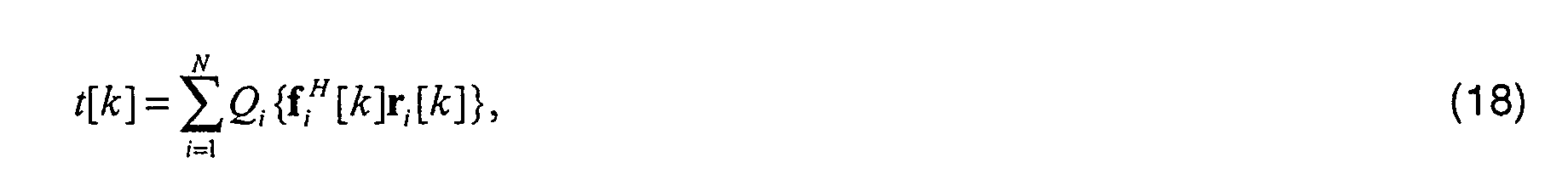
Es ist nun vorteilhaft, das Signal t[k] ebenfalls in der trellisbasierten Entzerrung zu
verwenden. Dazu wird das Signal s[k] nach Gl. (8) zuerst in der Form


Mit der vorgestellten zweikanaligen Struktur kann ein Diversity-Effekt und damit auch eine hohe Leistungsfähigkeit bei Verwendung kurzer DFE-Filter erzielt werden.With the presented two-channel structure, a diversity effect can be achieved high performance can be achieved when using short DFE filters.
Claims (13)
falls die Anzahl der Projektionen Pi eins beträgt:
if the number of projections P i is one:
wobei in Schritt c1) und/oder in Schritt d2) die Einrichtung zur Detektion zur Entzerrung ausgebildet ist.Method according to claim 1,
wherein in step c1) and / or in step d2) the detection device is designed for equalization.
dadurch gekennzeichnet, daß in Schritt d1) alle Projektionen Pi zur Bildung des Summensignals s[k] summiert werden.Method according to claim 1 or 2,
characterized in that in step d1) all projections P i are summed to form the sum signal s [k].
dadurch gekennzeichnet, daß mindestens zwei Empfangssignale ri [k] vorliegen und die zugehörigen mindestens zwei Ausgangssignale yi [k] in Schritt b) auf identische Richtungsvektoren projiziert werden.Method according to one of the preceding claims,
characterized in that at least two received signals r i [k] are present and the associated at least two output signals y i [k] are projected onto identical direction vectors in step b).
dadurch gekennzeichnet, daß für die Filterung der Empfangssignale in Schritt a) Feedforward-Filter einer DFE mit reellwertigem Feedback-Filter verwendet werden, die insbesondere gemäß den Kriterien ZF, MMSE, maximaler Störabstand oder Impulsverkürzung optimiert werden.Method according to one of the preceding claims,
characterized in that feedforward filters of a DFE with real feedback filter are used for filtering the received signals in step a), which are optimized in particular according to the criteria ZF, MMSE, maximum signal-to-noise ratio or pulse shortening.
dadurch gekennzeichnet, daß zur Optimierung der Filterkoeffizienten die Signale nach den Projektionen herangezogen werden.Method according to one of the preceding claims,
characterized in that the signals after the projections are used to optimize the filter coefficients.
dadurch gekennzeichnet, daß zur Einstellung der Filterkoeffizienten des mindestens einen komplexwertigen Filters ein adaptiver Algorithmus verwendet wird.Method according to one of the preceding claims,
characterized in that an adaptive algorithm is used to set the filter coefficients of the at least one complex filter.
dadurch gekennzeichnet, daß der adaptive Algorithmus zur Einstellung der Filterkoeffizienten eine dem Empfänger bekannte Trainingssequenz verwendet.Method according to claim 7,
characterized in that the adaptive algorithm for setting the filter coefficients uses a training sequence known to the receiver.
dadurch gekennzeichnet, daß ein adaptiver Algorithmus zur Einstellung der Filterkoeffizienten verwendet wird, ohne Verwendung einer im Empfänger bekannten Trainingssequenz.Method according to claim 7,
characterized in that an adaptive algorithm for setting the filter coefficients is used without using a training sequence known in the receiver.
dadurch gekennzeichnet, daß die zugehörigen orthogonalen Komplemente der Projektionen von mindestens einem gefilterten Ausgangssignal yi [k] berechnet werden.Method according to one of the preceding claims,
characterized in that the associated orthogonal complements of the projections are calculated from at least one filtered output signal y i [ k ].
wobei die zu unterdrückende Interferenz zumindest durch einen Teil der Sendesignale bei sendeseitiger Antennendiversität dargestellt wird.Method according to one of the preceding claims 1 to 10,
the interference to be suppressed being represented by at least some of the transmission signals with antenna diversity on the transmission side.
falls die Anzahl der Projektionen P i eins beträgt:
falls die Anzahl der Projektionen Pi zwei und mehr beträgt:
if the number of projections P i is one:
if the number of projections P i is two or more:
dadurch gekennzeichnet, daß er weiterhin folgende Funktionen umfasst:
falls die Anzahl der Projektionen Pi zwei und mehr beträgt:
characterized in that it also includes the following functions:
if the number of projections P i is two or more:
Priority Applications (1)
| Application Number | Priority Date | Filing Date | Title |
|---|---|---|---|
| EP03019288A EP1367759B1 (en) | 2000-12-28 | 2001-10-04 | Receiver for interference suppression in a TDMA and/or FDMA transmission |
Applications Claiming Priority (4)
| Application Number | Priority Date | Filing Date | Title |
|---|---|---|---|
| EP00128664 | 2000-12-28 | ||
| EP00128664 | 2000-12-28 | ||
| EP01123779A EP1221780B1 (en) | 2000-12-28 | 2001-10-04 | Method and system for the interference suppression of a TDMA and/or FDMA transmission |
| EP03019288A EP1367759B1 (en) | 2000-12-28 | 2001-10-04 | Receiver for interference suppression in a TDMA and/or FDMA transmission |
Related Parent Applications (1)
| Application Number | Title | Priority Date | Filing Date |
|---|---|---|---|
| EP01123779A Division EP1221780B1 (en) | 2000-12-28 | 2001-10-04 | Method and system for the interference suppression of a TDMA and/or FDMA transmission |
Publications (2)
| Publication Number | Publication Date |
|---|---|
| EP1367759A1 true EP1367759A1 (en) | 2003-12-03 |
| EP1367759B1 EP1367759B1 (en) | 2005-05-04 |
Family
ID=26071699
Family Applications (2)
| Application Number | Title | Priority Date | Filing Date |
|---|---|---|---|
| EP03019288A Expired - Lifetime EP1367759B1 (en) | 2000-12-28 | 2001-10-04 | Receiver for interference suppression in a TDMA and/or FDMA transmission |
| EP01123779A Expired - Lifetime EP1221780B1 (en) | 2000-12-28 | 2001-10-04 | Method and system for the interference suppression of a TDMA and/or FDMA transmission |
Family Applications After (1)
| Application Number | Title | Priority Date | Filing Date |
|---|---|---|---|
| EP01123779A Expired - Lifetime EP1221780B1 (en) | 2000-12-28 | 2001-10-04 | Method and system for the interference suppression of a TDMA and/or FDMA transmission |
Country Status (13)
| Country | Link |
|---|---|
| US (1) | US7215726B2 (en) |
| EP (2) | EP1367759B1 (en) |
| JP (1) | JP4021324B2 (en) |
| KR (1) | KR100852012B1 (en) |
| CN (1) | CN1284322C (en) |
| AT (2) | ATE295029T1 (en) |
| AU (1) | AU2002240852B2 (en) |
| BR (1) | BR0116591A (en) |
| DE (2) | DE50106151D1 (en) |
| ES (1) | ES2206374T3 (en) |
| HK (1) | HK1049747B (en) |
| RU (1) | RU2285347C2 (en) |
| WO (1) | WO2002054660A1 (en) |
Cited By (1)
| Publication number | Priority date | Publication date | Assignee | Title |
|---|---|---|---|---|
| TWI422167B (en) * | 2006-08-24 | 2014-01-01 | Mstar France Sas | Interference cancellation receiver and method |
Families Citing this family (30)
| Publication number | Priority date | Publication date | Assignee | Title |
|---|---|---|---|---|
| US7340016B2 (en) | 2001-05-11 | 2008-03-04 | Telefonaktiebolaget Lm Ericsson (Publ) | Equalizers for multi-branch receiver |
| US7133477B2 (en) * | 2002-01-02 | 2006-11-07 | Intel Corporation | Robust low complexity multi-antenna adaptive minimum mean square error equalizer |
| DE10233835A1 (en) * | 2002-07-25 | 2004-02-12 | Robert Bosch Gmbh | Interference-free measurement method for use with signals that are subjected to pulsed interference of a known or determinable frequency and wherein at least three individual measurements are made with varying intervals |
| DE10239810A1 (en) * | 2002-08-29 | 2004-03-11 | Siemens Ag | Method and transmission device for transmitting data in a multi-carrier system |
| US7187736B2 (en) * | 2003-02-13 | 2007-03-06 | Motorola Inc. | Reducing interference in a GSM communication system |
| US7496164B1 (en) * | 2003-05-02 | 2009-02-24 | At&T Mobility Ii Llc | Systems and methods for interference cancellation in a radio receiver system |
| US20050036575A1 (en) * | 2003-08-15 | 2005-02-17 | Nokia Corporation | Method and apparatus providing low complexity equalization and interference suppression for SAIC GSM/EDGE receiver |
| US7450924B1 (en) * | 2004-03-25 | 2008-11-11 | At&T Mobility Ii Llc | Interference cancellation and receive diversity for single-valued modulation receivers |
| US8073088B2 (en) | 2004-03-25 | 2011-12-06 | Hewlett-Packard Development Company, L.P. | Method and communication device for interference cancellation in a cellular TDMA communication system |
| US7830975B2 (en) * | 2004-04-12 | 2010-11-09 | Nokia Corporation | I/Q MIMO detection for single antenna interference cancellation |
| FR2873877B1 (en) * | 2004-08-02 | 2006-12-01 | Wavecom Sa | METHOD FOR DESIGNING A DIGITAL RECEPTION FILTER AND CORRESPONDING RECEPTION DEVICE |
| KR20060012825A (en) * | 2004-08-04 | 2006-02-09 | 삼성전자주식회사 | Mimo receiver |
| DE102004059983B4 (en) * | 2004-12-13 | 2009-05-07 | Infineon Technologies Ag | Suppression of co-channel interference interference by means of a digital noise filter arrangement |
| DE602005007372D1 (en) * | 2005-12-22 | 2008-07-17 | Alcatel Lucent | OFDM coding using Hermite polynomials |
| US8036325B2 (en) * | 2006-03-09 | 2011-10-11 | Interdigital Technology Corporation | Wireless communication method and apparatus for performing knowledge-based and blind interference cancellation |
| US8031794B2 (en) * | 2006-05-09 | 2011-10-04 | At&T Mobility Ii Llc | Systems and methods for interference cancellation in a multiple antenna radio receiver system |
| US7961782B2 (en) | 2007-06-04 | 2011-06-14 | Infineon Technologies Ag | Interference suppression processing unit and a method of suppressing interference in wireless data communication |
| US7848460B2 (en) | 2007-07-12 | 2010-12-07 | Telefonaktiebolaget Lm Ericsson (Publ) | Interference suppression method and apparatus |
| US20090296803A1 (en) * | 2008-06-03 | 2009-12-03 | Mediatek Inc. | Block-based equalizer and method thereof |
| US8265205B2 (en) * | 2008-06-04 | 2012-09-11 | Mediatek Inc. | Receiver architecture |
| US20090304122A1 (en) * | 2008-06-04 | 2009-12-10 | Navid Fatemi-Ghomi | Receiver architecture |
| WO2010005923A1 (en) * | 2008-07-07 | 2010-01-14 | Augusta Technology Usa, Inc. | Co-channel interference and adjacent channel interference detection and suppression |
| CN101667845B (en) * | 2008-09-05 | 2013-03-20 | 中兴通讯股份有限公司 | Self-adapting combination method and self-adapting combination system for multi-channel signals |
| US8320478B2 (en) * | 2008-12-19 | 2012-11-27 | Entropic Communications, Inc. | System and method for generating a signal with a random low peak to average power ratio waveform for an orthogonal frequency division multiplexing system |
| CN101827045B (en) * | 2010-04-26 | 2013-06-05 | 华为技术有限公司 | Method for processing received signal and receiver |
| CN102780540B (en) * | 2012-06-26 | 2015-01-07 | 华为技术有限公司 | Erasure decoding method, device and receiver |
| RU2573270C2 (en) * | 2014-06-03 | 2016-01-20 | Открытое акционерное общество "Российский институт мощного радиостроения" | Adaptive correction method with compensation of guard time periods |
| US10057094B2 (en) * | 2016-05-10 | 2018-08-21 | Samsung Electronics Co., Ltd | Apparatus and method for single antenna interference cancellation (SAIC) enhancement |
| US11438197B2 (en) * | 2020-11-12 | 2022-09-06 | Texas Instruments Incorporated | Adaptive equalizer with a real feedforward filter and a single complex feedforward tap |
| CN113641342A (en) * | 2021-08-23 | 2021-11-12 | 苏州赛科智慧能源有限公司 | Data transmission method based on jersey framework |
Citations (1)
| Publication number | Priority date | Publication date | Assignee | Title |
|---|---|---|---|---|
| EP0669729A1 (en) * | 1994-02-25 | 1995-08-30 | Thomson-Csf | Method for implementing multichannel equalisation in a radio receiver in the presence of interferece and multipath propagation |
Family Cites Families (24)
| Publication number | Priority date | Publication date | Assignee | Title |
|---|---|---|---|---|
| JP2570967B2 (en) | 1993-07-08 | 1997-01-16 | 日本電気株式会社 | CDMA receiver |
| US5414728A (en) * | 1993-11-01 | 1995-05-09 | Qualcomm Incorporated | Method and apparatus for bifurcating signal transmission over in-phase and quadrature phase spread spectrum communication channels |
| JP2605615B2 (en) | 1993-12-30 | 1997-04-30 | 日本電気株式会社 | Spread spectrum receiver |
| US5619503A (en) * | 1994-01-11 | 1997-04-08 | Ericsson Inc. | Cellular/satellite communications system with improved frequency re-use |
| US6018317A (en) * | 1995-06-02 | 2000-01-25 | Trw Inc. | Cochannel signal processing system |
| US6697633B1 (en) * | 1995-06-02 | 2004-02-24 | Northrop Grummar Corporation | Method permitting increased frequency re-use in a communication network, by recovery of transmitted information from multiple cochannel signals |
| US6240098B1 (en) * | 1995-08-22 | 2001-05-29 | Thomson-Csf | Method and device for space division multiplexing of radio signals transmitted in cellular radio communications |
| US5687198A (en) * | 1996-01-04 | 1997-11-11 | Motorola, Inc. | Channel estimation in a communication system |
| US6430216B1 (en) * | 1997-08-22 | 2002-08-06 | Data Fusion Corporation | Rake receiver for spread spectrum signal demodulation |
| US6947474B2 (en) * | 1996-08-23 | 2005-09-20 | Tensorcomm, Inc. | Rake receiver for spread spectrum signal demodulation |
| KR100223757B1 (en) * | 1997-05-08 | 1999-10-15 | 김영환 | Equalizer |
| US6686879B2 (en) * | 1998-02-12 | 2004-02-03 | Genghiscomm, Llc | Method and apparatus for transmitting and receiving signals having a carrier interferometry architecture |
| IL123782A (en) * | 1998-03-22 | 2001-05-20 | Eci Telecom Ltd | Signal equalization |
| AT407933B (en) * | 1998-06-09 | 2001-07-25 | Juha Dipl Ing Laurila | METHOD FOR SEPARATING AND DETECTING SAME-CHANNEL SIGNALS |
| US6606129B1 (en) * | 1998-12-04 | 2003-08-12 | Samsung Electronics Co., Ltd. | Digital filtering of DTV I-F signal to avoid low-end boost of the baseband signal resulting from in-phase synchrodyne |
| US6925067B2 (en) * | 1999-04-23 | 2005-08-02 | Qualcomm, Incorporated | Configuration of overhead channels in a mixed bandwidth system |
| US6285720B1 (en) * | 1999-05-28 | 2001-09-04 | W J Communications, Inc. | Method and apparatus for high data rate wireless communications over wavefield spaces |
| US6574270B1 (en) * | 1999-07-30 | 2003-06-03 | Ericsson Inc. | Baseband interference canceling spread spectrum communications methods and apparatus |
| US6463105B1 (en) * | 1999-09-13 | 2002-10-08 | Ericsson Inc. | Methods and systems for estimation of the carrier to interference ratio for a wireless communication channel |
| US6515980B1 (en) * | 1999-09-22 | 2003-02-04 | Ericsson Inc. | Methods and apparatus for interference cancellation using complex interference orthogonalization techniques |
| US6934341B2 (en) * | 2000-08-29 | 2005-08-23 | Telefonaktiebolaget Lm Ericsson (Publ) | Method and apparatus for plurality signal generation |
| US6745050B1 (en) * | 2000-10-23 | 2004-06-01 | Massachusetts Institute Of Technology | Multichannel multiuser detection |
| US7061970B2 (en) * | 2000-11-14 | 2006-06-13 | Irving Reed | Self-synchronizing adaptive multistage receiver for wireless communication systems |
| US7012977B2 (en) * | 2000-12-29 | 2006-03-14 | Telefonaktiebolaget Lm Ericsson (Publ) | System, method and apparatus for wireless channel parameter estimation in spread spectrum communication systems |
-
2001
- 2001-10-04 ES ES01123779T patent/ES2206374T3/en not_active Expired - Lifetime
- 2001-10-04 AT AT03019288T patent/ATE295029T1/en not_active IP Right Cessation
- 2001-10-04 AT AT01123779T patent/ATE250830T1/en not_active IP Right Cessation
- 2001-10-04 EP EP03019288A patent/EP1367759B1/en not_active Expired - Lifetime
- 2001-10-04 DE DE50106151T patent/DE50106151D1/en not_active Expired - Lifetime
- 2001-10-04 DE DE50100673T patent/DE50100673D1/en not_active Expired - Lifetime
- 2001-10-04 EP EP01123779A patent/EP1221780B1/en not_active Expired - Lifetime
- 2001-12-19 KR KR1020037008696A patent/KR100852012B1/en not_active IP Right Cessation
- 2001-12-19 AU AU2002240852A patent/AU2002240852B2/en not_active Ceased
- 2001-12-19 WO PCT/EP2001/015019 patent/WO2002054660A1/en active IP Right Grant
- 2001-12-19 BR BR0116591-7A patent/BR0116591A/en not_active IP Right Cessation
- 2001-12-19 JP JP2002555028A patent/JP4021324B2/en not_active Expired - Fee Related
- 2001-12-19 CN CNB018214754A patent/CN1284322C/en not_active Expired - Fee Related
- 2001-12-19 RU RU2003123123/09A patent/RU2285347C2/en not_active IP Right Cessation
- 2001-12-19 US US10/027,657 patent/US7215726B2/en not_active Expired - Fee Related
-
2003
- 2003-01-09 HK HK03100245.0A patent/HK1049747B/en not_active IP Right Cessation
Patent Citations (1)
| Publication number | Priority date | Publication date | Assignee | Title |
|---|---|---|---|---|
| EP0669729A1 (en) * | 1994-02-25 | 1995-08-30 | Thomson-Csf | Method for implementing multichannel equalisation in a radio receiver in the presence of interferece and multipath propagation |
Non-Patent Citations (2)
| Title |
|---|
| ARIYAVISITAKUL S ET AL: "JOINT EQUALIZATION AND INTERFERENCE SUPPRESSION FOR HIGH DATA RATE WIRELESS SYSTEMS", HOUSTON, TX, MAY 16 - 20, 1999,NEW YORK, NY: IEEE,US, vol. CONF. 49, 1999, pages 700 - 706, XP000937866, ISBN: 0-7803-5566-0 * |
| LO B C W ET AL: "ADAPTIVE EQUALIZATION AND INTERFERENCE CANCELLATION FOR WIRELESS COMMUNICATION SYSTEMS", IEEE TRANSACTIONS ON COMMUNICATIONS,IEEE INC. NEW YORK,US, vol. 47, no. 4, April 1999 (1999-04-01), pages 538 - 544, XP000860509, ISSN: 0090-6778 * |
Cited By (1)
| Publication number | Priority date | Publication date | Assignee | Title |
|---|---|---|---|---|
| TWI422167B (en) * | 2006-08-24 | 2014-01-01 | Mstar France Sas | Interference cancellation receiver and method |
Also Published As
| Publication number | Publication date |
|---|---|
| US7215726B2 (en) | 2007-05-08 |
| DE50106151D1 (en) | 2005-06-09 |
| KR20030070083A (en) | 2003-08-27 |
| CN1284322C (en) | 2006-11-08 |
| CN1593029A (en) | 2005-03-09 |
| US20020141437A1 (en) | 2002-10-03 |
| ES2206374T3 (en) | 2004-05-16 |
| WO2002054660B1 (en) | 2002-09-19 |
| RU2003123123A (en) | 2005-01-27 |
| EP1367759B1 (en) | 2005-05-04 |
| ATE295029T1 (en) | 2005-05-15 |
| WO2002054660A1 (en) | 2002-07-11 |
| JP2004523154A (en) | 2004-07-29 |
| DE50100673D1 (en) | 2003-10-30 |
| RU2285347C2 (en) | 2006-10-10 |
| ATE250830T1 (en) | 2003-10-15 |
| HK1049747A1 (en) | 2003-05-23 |
| EP1221780B1 (en) | 2003-09-24 |
| BR0116591A (en) | 2003-12-23 |
| KR100852012B1 (en) | 2008-08-12 |
| AU2002240852B2 (en) | 2005-09-15 |
| JP4021324B2 (en) | 2007-12-12 |
| EP1221780A1 (en) | 2002-07-10 |
| HK1049747B (en) | 2004-07-23 |
Similar Documents
| Publication | Publication Date | Title |
|---|---|---|
| EP1221780B1 (en) | Method and system for the interference suppression of a TDMA and/or FDMA transmission | |
| DE69521050T2 (en) | METHOD AND DEVICE FOR INTERFERENCE SUPPRESSION IN A DIGITAL CELLULAR MULTIPLE-ANTENNA COMMUNICATION SYSTEM | |
| DE60102798T2 (en) | TWO LEARNING USE DESCRIBE | |
| DE69412288T2 (en) | METHOD AND DEVICE FOR MULTIPLE USER INTERFERENCE REDUCTION | |
| DE69219048T2 (en) | Receiving a digital TDMA data signal with compensation for channel changes | |
| DE19904059B4 (en) | Equalizer detector system and method of designing an equalizer with multiple multipliers | |
| DE69825055T2 (en) | METHOD AND DEVICE FOR COMMON DEMODULATION OF NEIGHBORING CANAL SIGNALS IN DIGITAL COMMUNICATION SYSTEMS | |
| EP0349603B1 (en) | Process and arrangement for equalizing dispersive, linear or approximately linear channels for transmitting digital signals | |
| DE60019091T2 (en) | Radio communication system | |
| DE102010004178A1 (en) | Apparatus and method for compensation and identification of crosstalk | |
| DE112004002700B4 (en) | Method and apparatus for reducing crosstalk in a MIMO transmission system | |
| DE19826036C2 (en) | Method for separating several superimposed coded user signals | |
| EP1501234A1 (en) | Method and device to determine the dominant type of distortion | |
| EP0921664B1 (en) | Method for digital information transmission | |
| DE102009029871B4 (en) | Receiving and processing data | |
| DE69722792T2 (en) | MLSE DECODER WITH NEURONAL NETWORK | |
| EP1964344B1 (en) | Method and equaliser for detecting data symbol sequences from a received signal containing said sequences, transmitted via a time-variable transmission channel | |
| DE60318398T2 (en) | Method for noise suppression by means of an iterative, semi-blind channel estimation | |
| DE60034306T2 (en) | Method and receiver for estimating channel impact responses for the equalization of digital signals | |
| DE10111496A1 (en) | Signals correction procedure e.g. for telecommunications engineering, involves processing received signal in forward branch of equalizer | |
| DE10205742C1 (en) | Transmission channel pulse response estimation device has channel pulse response estimation passed through correction filter | |
| DE10223445B4 (en) | Digital linear equalizer filter | |
| EP1061664B1 (en) | Recovering of spread data from a composite signal in the frequency domain | |
| DE102006040279B4 (en) | Method and arrangement for transmitting radio signals with multiple parallel data streams with reduced computational complexity | |
| EP1964345B1 (en) | Method and equaliser for equalising a data symbol sequence captured by a time-variable transmission channel |
Legal Events
| Date | Code | Title | Description |
|---|---|---|---|
| PUAI | Public reference made under article 153(3) epc to a published international application that has entered the european phase |
Free format text: ORIGINAL CODE: 0009012 |
|
| 17P | Request for examination filed |
Effective date: 20030826 |
|
| AC | Divisional application: reference to earlier application |
Ref document number: 1221780 Country of ref document: EP Kind code of ref document: P |
|
| AK | Designated contracting states |
Kind code of ref document: A1 Designated state(s): AT BE CH CY DE DK ES FI FR GB GR IE IT LI LU MC NL PT SE TR |
|
| 17Q | First examination report despatched |
Effective date: 20040123 |
|
| AKX | Designation fees paid |
Designated state(s): AT BE CH CY DE DK ES FI FR GB GR IE IT LI LU MC NL PT SE TR |
|
| GRAP | Despatch of communication of intention to grant a patent |
Free format text: ORIGINAL CODE: EPIDOSNIGR1 |
|
| RTI1 | Title (correction) |
Free format text: RECEIVER FOR INTERFERENCE SUPPRESSION IN A TDMA AND/OR FDMA TRANSMISSION |
|
| GRAS | Grant fee paid |
Free format text: ORIGINAL CODE: EPIDOSNIGR3 |
|
| GRAA | (expected) grant |
Free format text: ORIGINAL CODE: 0009210 |
|
| AC | Divisional application: reference to earlier application |
Ref document number: 1221780 Country of ref document: EP Kind code of ref document: P |
|
| AK | Designated contracting states |
Kind code of ref document: B1 Designated state(s): AT BE CH CY DE DK ES FI FR GB GR IE IT LI LU MC NL PT SE TR |
|
| PG25 | Lapsed in a contracting state [announced via postgrant information from national office to epo] |
Ref country code: IE Free format text: LAPSE BECAUSE OF FAILURE TO SUBMIT A TRANSLATION OF THE DESCRIPTION OR TO PAY THE FEE WITHIN THE PRESCRIBED TIME-LIMIT Effective date: 20050504 Ref country code: FI Free format text: LAPSE BECAUSE OF FAILURE TO SUBMIT A TRANSLATION OF THE DESCRIPTION OR TO PAY THE FEE WITHIN THE PRESCRIBED TIME-LIMIT Effective date: 20050504 Ref country code: TR Free format text: LAPSE BECAUSE OF FAILURE TO SUBMIT A TRANSLATION OF THE DESCRIPTION OR TO PAY THE FEE WITHIN THE PRESCRIBED TIME-LIMIT Effective date: 20050504 Ref country code: NL Free format text: LAPSE BECAUSE OF FAILURE TO SUBMIT A TRANSLATION OF THE DESCRIPTION OR TO PAY THE FEE WITHIN THE PRESCRIBED TIME-LIMIT Effective date: 20050504 |
|
| REG | Reference to a national code |
Ref country code: GB Ref legal event code: FG4D Free format text: NOT ENGLISH |
|
| REG | Reference to a national code |
Ref country code: CH Ref legal event code: EP |
|
| REG | Reference to a national code |
Ref country code: IE Ref legal event code: FG4D Free format text: LANGUAGE OF EP DOCUMENT: GERMAN |
|
| REF | Corresponds to: |
Ref document number: 50106151 Country of ref document: DE Date of ref document: 20050609 Kind code of ref document: P |
|
| PG25 | Lapsed in a contracting state [announced via postgrant information from national office to epo] |
Ref country code: GR Free format text: LAPSE BECAUSE OF FAILURE TO SUBMIT A TRANSLATION OF THE DESCRIPTION OR TO PAY THE FEE WITHIN THE PRESCRIBED TIME-LIMIT Effective date: 20050804 Ref country code: SE Free format text: LAPSE BECAUSE OF FAILURE TO SUBMIT A TRANSLATION OF THE DESCRIPTION OR TO PAY THE FEE WITHIN THE PRESCRIBED TIME-LIMIT Effective date: 20050804 Ref country code: DK Free format text: LAPSE BECAUSE OF FAILURE TO SUBMIT A TRANSLATION OF THE DESCRIPTION OR TO PAY THE FEE WITHIN THE PRESCRIBED TIME-LIMIT Effective date: 20050804 |
|
| PG25 | Lapsed in a contracting state [announced via postgrant information from national office to epo] |
Ref country code: ES Free format text: LAPSE BECAUSE OF FAILURE TO SUBMIT A TRANSLATION OF THE DESCRIPTION OR TO PAY THE FEE WITHIN THE PRESCRIBED TIME-LIMIT Effective date: 20050815 |
|
| PG25 | Lapsed in a contracting state [announced via postgrant information from national office to epo] |
Ref country code: CY Free format text: LAPSE BECAUSE OF FAILURE TO SUBMIT A TRANSLATION OF THE DESCRIPTION OR TO PAY THE FEE WITHIN THE PRESCRIBED TIME-LIMIT Effective date: 20051004 Ref country code: AT Free format text: LAPSE BECAUSE OF NON-PAYMENT OF DUE FEES Effective date: 20051004 |
|
| PG25 | Lapsed in a contracting state [announced via postgrant information from national office to epo] |
Ref country code: PT Free format text: LAPSE BECAUSE OF FAILURE TO SUBMIT A TRANSLATION OF THE DESCRIPTION OR TO PAY THE FEE WITHIN THE PRESCRIBED TIME-LIMIT Effective date: 20051017 |
|
| GBT | Gb: translation of ep patent filed (gb section 77(6)(a)/1977) |
Effective date: 20050922 |
|
| PG25 | Lapsed in a contracting state [announced via postgrant information from national office to epo] |
Ref country code: MC Free format text: LAPSE BECAUSE OF NON-PAYMENT OF DUE FEES Effective date: 20051031 Ref country code: CH Free format text: LAPSE BECAUSE OF NON-PAYMENT OF DUE FEES Effective date: 20051031 Ref country code: LI Free format text: LAPSE BECAUSE OF NON-PAYMENT OF DUE FEES Effective date: 20051031 Ref country code: BE Free format text: LAPSE BECAUSE OF NON-PAYMENT OF DUE FEES Effective date: 20051031 Ref country code: LU Free format text: LAPSE BECAUSE OF NON-PAYMENT OF DUE FEES Effective date: 20051031 |
|
| NLV1 | Nl: lapsed or annulled due to failure to fulfill the requirements of art. 29p and 29m of the patents act | ||
| REG | Reference to a national code |
Ref country code: IE Ref legal event code: FD4D |
|
| PLBE | No opposition filed within time limit |
Free format text: ORIGINAL CODE: 0009261 |
|
| STAA | Information on the status of an ep patent application or granted ep patent |
Free format text: STATUS: NO OPPOSITION FILED WITHIN TIME LIMIT |
|
| ET | Fr: translation filed | ||
| 26N | No opposition filed |
Effective date: 20060207 |
|
| REG | Reference to a national code |
Ref country code: CH Ref legal event code: PL |
|
| BERE | Be: lapsed |
Owner name: COM-RESEARCH G.M.B.H. SOLUTIONS FOR COMMUNICATION Effective date: 20051031 |
|
| PGFP | Annual fee paid to national office [announced via postgrant information from national office to epo] |
Ref country code: DE Payment date: 20121031 Year of fee payment: 12 Ref country code: FR Payment date: 20121113 Year of fee payment: 12 |
|
| PGFP | Annual fee paid to national office [announced via postgrant information from national office to epo] |
Ref country code: GB Payment date: 20121023 Year of fee payment: 12 Ref country code: IT Payment date: 20121025 Year of fee payment: 12 |
|
| GBPC | Gb: european patent ceased through non-payment of renewal fee |
Effective date: 20131004 |
|
| REG | Reference to a national code |
Ref country code: DE Ref legal event code: R119 Ref document number: 50106151 Country of ref document: DE Effective date: 20140501 |
|
| PG25 | Lapsed in a contracting state [announced via postgrant information from national office to epo] |
Ref country code: GB Free format text: LAPSE BECAUSE OF NON-PAYMENT OF DUE FEES Effective date: 20131004 |
|
| REG | Reference to a national code |
Ref country code: FR Ref legal event code: ST Effective date: 20140630 |
|
| PG25 | Lapsed in a contracting state [announced via postgrant information from national office to epo] |
Ref country code: FR Free format text: LAPSE BECAUSE OF NON-PAYMENT OF DUE FEES Effective date: 20131031 Ref country code: IT Free format text: LAPSE BECAUSE OF NON-PAYMENT OF DUE FEES Effective date: 20131004 Ref country code: DE Free format text: LAPSE BECAUSE OF NON-PAYMENT OF DUE FEES Effective date: 20140501 |