EP1367699A2 - Method and apparatus for manufacturing electric motor - Google Patents
Method and apparatus for manufacturing electric motor Download PDFInfo
- Publication number
- EP1367699A2 EP1367699A2 EP03011769A EP03011769A EP1367699A2 EP 1367699 A2 EP1367699 A2 EP 1367699A2 EP 03011769 A EP03011769 A EP 03011769A EP 03011769 A EP03011769 A EP 03011769A EP 1367699 A2 EP1367699 A2 EP 1367699A2
- Authority
- EP
- European Patent Office
- Prior art keywords
- motor housing
- stator core
- core
- core components
- cylindrical body
- Prior art date
- Legal status (The legal status is an assumption and is not a legal conclusion. Google has not performed a legal analysis and makes no representation as to the accuracy of the status listed.)
- Granted
Links
Images


Classifications
-
- H—ELECTRICITY
- H02—GENERATION; CONVERSION OR DISTRIBUTION OF ELECTRIC POWER
- H02K—DYNAMO-ELECTRIC MACHINES
- H02K15/00—Processes or apparatus specially adapted for manufacturing, assembling, maintaining or repairing of dynamo-electric machines
- H02K15/02—Processes or apparatus specially adapted for manufacturing, assembling, maintaining or repairing of dynamo-electric machines of stator or rotor bodies
- H02K15/021—Magnetic cores
- H02K15/022—Magnetic cores with salient poles
-
- H—ELECTRICITY
- H02—GENERATION; CONVERSION OR DISTRIBUTION OF ELECTRIC POWER
- H02K—DYNAMO-ELECTRIC MACHINES
- H02K15/00—Processes or apparatus specially adapted for manufacturing, assembling, maintaining or repairing of dynamo-electric machines
- H02K15/12—Impregnating, moulding insulation, heating or drying of windings, stators, rotors or machines
-
- Y—GENERAL TAGGING OF NEW TECHNOLOGICAL DEVELOPMENTS; GENERAL TAGGING OF CROSS-SECTIONAL TECHNOLOGIES SPANNING OVER SEVERAL SECTIONS OF THE IPC; TECHNICAL SUBJECTS COVERED BY FORMER USPC CROSS-REFERENCE ART COLLECTIONS [XRACs] AND DIGESTS
- Y10—TECHNICAL SUBJECTS COVERED BY FORMER USPC
- Y10T—TECHNICAL SUBJECTS COVERED BY FORMER US CLASSIFICATION
- Y10T29/00—Metal working
- Y10T29/49—Method of mechanical manufacture
- Y10T29/49002—Electrical device making
- Y10T29/49009—Dynamoelectric machine
-
- Y—GENERAL TAGGING OF NEW TECHNOLOGICAL DEVELOPMENTS; GENERAL TAGGING OF CROSS-SECTIONAL TECHNOLOGIES SPANNING OVER SEVERAL SECTIONS OF THE IPC; TECHNICAL SUBJECTS COVERED BY FORMER USPC CROSS-REFERENCE ART COLLECTIONS [XRACs] AND DIGESTS
- Y10—TECHNICAL SUBJECTS COVERED BY FORMER USPC
- Y10T—TECHNICAL SUBJECTS COVERED BY FORMER US CLASSIFICATION
- Y10T29/00—Metal working
- Y10T29/49—Method of mechanical manufacture
- Y10T29/49002—Electrical device making
- Y10T29/49009—Dynamoelectric machine
- Y10T29/49012—Rotor
-
- Y—GENERAL TAGGING OF NEW TECHNOLOGICAL DEVELOPMENTS; GENERAL TAGGING OF CROSS-SECTIONAL TECHNOLOGIES SPANNING OVER SEVERAL SECTIONS OF THE IPC; TECHNICAL SUBJECTS COVERED BY FORMER USPC CROSS-REFERENCE ART COLLECTIONS [XRACs] AND DIGESTS
- Y10—TECHNICAL SUBJECTS COVERED BY FORMER USPC
- Y10T—TECHNICAL SUBJECTS COVERED BY FORMER US CLASSIFICATION
- Y10T29/00—Metal working
- Y10T29/53—Means to assemble or disassemble
- Y10T29/5313—Means to assemble electrical device
- Y10T29/53143—Motor or generator
Definitions
- the present invention relates to a method and apparatus for manufacturing an electric motor of the type wherein a cylindrical stator core circumferentially dividable to plural core components is shrinkage-fit in a circular internal surface of a motor housing.
- a stator core is constituted, taking the work-to-easy capability in winding process into consideration, by effecting a winding process on each of the core components and then by integrating the core components. Then, a shrinkage fitting process is carried out. Specifically, the stator core is inserted into a thermally expanded cylindrical housing, whereby the stator core is securely tightened circumferentially within the cylindrical housing which then shrinks thermally to a smaller diameter.
- the respective core components displaces with each another in the course of the cylindrical housing shrinking thermally. This causes air gaps between the stator core and a rotor around the same to be uneven, so that an unfavorable influence is exerted on the torque performance or the like of the electric motor so manufactured.
- a method of manufacturing an electric motor by fitting a cylindrical stator core circumferentially dividable to plural core components, into a circular internal surface of a motor housing.
- the method comprises the steps of thermally expanding the motor housing; inserting the stator core inside the thermally expanded motor housing; and thermally contracting the housing with the core components being kept pressed on the circular internal surface of the motor housing.
- the stator core can be secured within the motor housing without using any positive clamping means, and the plural core components can be secured bodily as a whole without providing any clearance between the external surface of the stator core and the circular internal surface of the motor housing. Therefore, the motor manufactured by the method of the present invention can be simple in construction, inexpensive in cost and reliable in operation.
- the method includes the step of expanding the core components radially outward within the thermally expanded motor housing thereby to press the core components on the circular internal surface of the motor housing prior to the step of thermally contracting the motor housing.
- the plural core components constituting the stator core are radially inwardly displaced bodily with the motor housing while the same is contracted as time goes.
- an apparatus for manufacturing an electric motor wherein a cylindrical stator core circumferentially dividable to plural core components are inserted into a circular internal surface of a motor housing.
- a pressing device is provided for pressing the core components from the Inside of the stator core onto the circular internal surface of the motor housing having been thermally expanded.
- the core components are pressed radially outward to closely fit in the circular internal surface of the motor housing.
- the motor housing is then contracted to a smaller diameter, the core components are displaced radially inwardly and finally secured with each component being pressed by the circular internal surface and thereby being brought into abutting engagement with two components next thereto, This provides a rigid assembling of the motor housing and the stator core.
- An electric motor 10 shown in Figure 1 is a brushless motor incorporating a stator core 12 within a motor housing 11.
- the motor housing 11 is made of, for example, aluminum casting, takes a cylindrical form opening at both ends thereof and is machined to be round at the internal surface thereof.
- the stator core 12 also takes a cylindrical form with both ends opening as a whole and is of the configuration that it is circumferentially dividable into plural core components 14. More specifically, the stator core 12 has twelve (12) teeth 13 for example and is dividable into twelve core components 14 on a tooth-by-tooth basis.
- each core component 14 After winding process is performed on each core component 14 as described later in detail, the group of the core components 14 are united bodily to constitute a cylindrical stator core 12, which is then secured by shrinkage fit onto the circular internal surface of the motor housing 11.
- a motor manufacturing apparatus 30 which the present invention is applied to is used for implementing the shrinkage fit.
- the motor manufacturing apparatus 30 is shown having a fixed table 32 on the top portions of a plurality of guide posts 31.
- the fixed table 32 has formed a through bore 33 extending therethrough, and a housing fixing portion 35 is provided on the top surface of a surrounding wall 34 which is upstanding from the edge portion around the through bore 33.
- the housing fixing portion 35 is formed with a fixing base 36 whose ends open upward and downward respectively, and the motor housing 11 is fit at its one end in the upper end portion of the fixing base 36 with a flange 11F provided on the motor housing 11 being screwed into the housing fixing portion 35.
- a movable table 40 is provided under the fixed table 32 in face-to-face relation.
- the movable table 40 has cylinder devices (or hydraulic jacks) as a drive source provided at the lower surface thereof and is moved thereby up and down along the guide posts 31.
- the movable table 40 is displaceable to an end position where stops 39 protruding from the upper surface of the movable table 40 are brought into abutting engagement with stop rests 38 provided at the lower surface of the fixed table 32.
- a cylindrical support sleeve 41 is upright from the movable table 40 in axial alignment with the aforementioned housing fixing portion 35 and mounts an insertion guide head 50 on the top thereof.
- the insertion guide head 50 is assembled by fitting a base portion 52, a vertical split cylindrical body 53, a tapered shaft or sleeve 54 and a pressing assembly 55 in order over a straight-motion shaft 51 extending vertically.
- the base portion 52, the vertical split cylindrical body 53, the tapered sleeve 54 and the pressing assembly 55 constitute a pressing mechanism which presses the core components 14 from the inside of the stator core 12 on the circular internal surface of the motor housing 11 while the same is thermally expanded, as described later in detail.
- the insertion guide head 50 incorporates the pressing mechanism therein.
- An upper end nut 74 is screwed at the upper end of the straight-motion shaft 51 to prevent the pressing assembly 55 from coming off the straight-motion shaft 51.
- a lower end nut 75 is screwed at the lower end portion of the straight-motion shaft 51 to prevent the base portion 52 from coming off the straight-motion shaft 51.
- the base portion 52 includes a hood member 64 which is fit over the external surface of a cylindrical base body 63.
- the hood member 64 is formed with a cylindrical wall 65 which is upstanding form the circumferential edge portion of a disc 64C which is fixedly fit over the cylindrical base body 63.
- the stator core 12 is placed on an annular top surface of the cylindrical wall 65.
- the external diameter of the cylindrical wall 65 is made slightly smaller than that of the stator core 12, so that cylindrical wall 65 is able to pass through the bore of a temporarily holding ring 80.
- the ring 80 is fit over the external surface of the stator core 12 in the axial mid position thereof for temporarily holding the stator core 12.
- the cylindrical wall 65 upwardly protrudes a positioning pin 66 from a portion on the upper edge of the cylindrical wall 65.
- the positioning pin 66 is inserted with a play into one of axial through holes 18 which are formed in the core components 14 constituting the stator core 12.
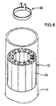
- the vertical split cylindrical body 53 takes a cylindrical shape as a whole as shown in Figure 2 which is able to be inserted within the stator core 12 with a play, and is of the configuration that it is circumferentially dividable into a plurality of sector members 56 as shown in Figure 4, More specifically, the vertical split cylindrical body 53 is constituted by twelve pieces of the sector members 56 which are the same in number as the twelve pieces of the core components 14 constituting the stator core 12.
- the axial opposite end portions of the vertical split cylindrical body 53 are made slightly smaller in diameter than the middle portion thereof, and arresting rings 57U, 57D are fit respectively over the small diameter end portions, as shown in Figure 3. These arresting rings 57U, 57D hold the sector members 56 in a cylindrical shape and allow the sector members 56 to slightly displace in radial directions thereof.
- the lower arresting ring 57D is partly fit over the base portion 52 (i.e., the cylindrical base body 63) and is vertically sandwiched between the base portion 52 and a stepped portion of the vertical split cylindrical body 53, so that the lower arresting ring 57D is fixed not to be movable vertically.
- annular grooves 58, 58 are circumferentially extended at two parts spaced in the axis direction of the vertical split cylindrical body 53 to encircle the sector members 56,
- An O-ring 59 constituting an annular elastic member is fit in each of the annular grooves 58 with itself being deformed to be stretched.
- the vertical split cylindrical body 53 is normally held in the state of a minimum diameter thereof with every adjoining sector members 56 being brought to fit closely with each other.
- Each of the sector members 56 is formed with a guide groove 60 which extends radially from the center or axis of the vertical split cylindrical body 53. Twelve guide pins 61 (only one shown in Figure 3) which are upstanding from the upper surface of the cylindrical base body 63 are fit respectively in the guide grooves 60 to serve as cam followers.
- the diameter of the upper portion is made larger than that of the lower portion, and a taper surface 62 is formed at the middle portion to become large gradually as it goes up.
- a return coil spring 68 is retained inside the lower part of the vertical split cylindrical body 53. The coil spring 68 is resiliently deformed when sandwiched between the tapered sleeve 54 and the base portion 52.
- the tapered sleeve 54 is formed with an external taper surface which is made smaller as it goes down, and is fit at its the external taper surface in an inner taper surface 62 of the vertical split cylindrical body 53.
- Slide bearings 54J are press-fit inside the tapered sleeve 54 thereby to reduce the sliding resistance against the straight-motion shaft 51.
- the construction of the pressing assembly 55 is such that a thrusting coil spring 71 as a pressing resilient member is retained inside a spring retainer cylinder 70 having a bottom at the lower end and that a pressing sleeve 72 is inserted into the spring retainer cylinder 70 from the upper opening thereof.
- the thrusting coil spring 71 is deformable to be compressed between the pressing sleeve 72 and the bottom of the spring retainer cylinder 70.
- An anti-coming-off sleeve 73 is secured by means of bolts to an outer flange 72J which extend laterally from the upper end of the pressing sleeve 72, and an inner flange 73K is radially inwardly extended from the lower end of the anti-coming-off sleeve 73.
- An outer flange 70F extending outwardly from the upper end of the spring retainer cylinder 70 is placed between the inner flange 73K and the outer flange 72J in a vertical direction to limit the relative motion distance between the spring retainer cylinder 70 and the pressing sleeve 72 to a predetermined distance.
- the aforementioned insertion guide head 50 downwardly protrudes a centering boss 67 from the center of the lower surface of the base portion 52 and is mounted on the cylindrical support sleeve 41 with the centering boss 67 being fit in the cylindrical support sleeve 41.
- the straight-motion shaft 51 of the insertion guide head 50 is formed with a screw portion at the lower end thereof and the screw portion is joined with a relay shaft 76 which is vertically movable within the cylindrical support sleeve 41.
- a cross hole 77 is formed to extend across the lower end portion of the cylindrical support sleeve 41.
- the cross hole 77 is an elongated hole which is elongated vertically.
- a cross bar 78 passes through the cross hole 77 and is secured at the center thereof to the lower end portion of the relay shaft 76 with opposite ends thereof projecting from the cross hole 77.
- the opposite end portions of the cross bar 78 are brought into abutting engagement with bar stops 79, 79 provided at the lower surface of the fixed table 32.
- the relay shaft 76 is drawn downwardly relative to the cylindrical support sleeve 41.
- the position that the upper end nut 74 takes when the relay shaft 76 is drawn to the lowermost end position is defined as first position
- the position that the upper end nut 74 takes before the cross bar 78 is brought into abutting engagement with the bar stops 79, that is, before the relay shaft 76 is drawn downwardly is defined as second position.
- a temporarily holding ring 80 is fit over the external surface of the stator core 12.
- the temporarily holding ring 80 is made by forming a round through hole in a flat plate and providing a cylindrical wall upstanding from the opening edge portion of the flat plate.
- stator core 12 is disassembled to respective core components 14, and an electric wire is wound around each core component 14 along coil retaining slots 17, 17 opening at both lateral sides thereof.
- a coil 15 is constituted on each core component 14.
- both terminals (not shown) of each coil 15 are left drawn to one end in axial direction of the core component 14.
- the core components 14 are assembled to constitute a cylindrical stator core 12 with a temporarily holding ring 80 being fit over the external surface thereof.
- the core components 14 are oriented to gather the both terminals of the coil 15 on each core component 14 at the same side in axial direction of the stator core 12.
- a wire connection ring 19 is coupled to one axial end of the stator core 12 to which end the terminals of the coils 15 have been gathered.
- the wire connection ring 19 is provided with twelve pins 20 protruding from an axial one end of an annular body 21, as shown in Figure 1.
- the wire connection ring 19 is connected to the stator core 12 with the pins 20 being inserted respectively into the axial through holes 18 which are formed in the core components 14 therethrough.
- the terminals of each coil 15 are secured to those suitable of three conductive rings (not shown) which are provided on the wire connection ring 19, so that the coils 15 are connected to one after another thereby to constitute a three-phase coil assembly as a whole.
- stator core 12 is fit over the external surface of the insertion guide head 50 of the motor manufacturing apparatus 30.
- a positioning pin 66 protruding from the food portion 64 is inserted into one of the axial through holes 18 of the core components 14 and the stator core 12 is mounted at the lower surface thereof on the annular upper surface of the food portion 64 provided on the base portion 52 of the insertion guide head 50.
- the stator core 12 is held with the core components 14 thereof respectively facing the sector members 56 of the vertical split cylindrical body 53 in a one-to-one relation.
- the motor housing 11 heated in advance is secured to a housing fixing portion 35, after which the motor manufacturing apparatus 30 is put into operation.
- the insertion guide head 50 and the stator core 12 together with the movable table 40 are moved up, and the stator core 12 enters the motor housing 11. Since the motor housing 11 has been expanded thermally, the stator core 12 is smoothly inserted into the motor housing 11 with a certain clearance being secured therebetween.
- the temporarily holding ring 80 is brought into abutting engagement with the lower surface of the housing fixing portion 35 thereby to come off from the stator core 12, and the base portion 52 of the insertion guide head 50 passes through the temporarily holding ring 80, whereby the entirety of the stator core 12 is inserted into the motor housing 11 to the axial center position of the same.
- the cross bar 78 is brought into abutting engagement at its opposite ends with the bar stops 79, 79 secured to the lower surface of the fixed table 32, nevertheless the movable table 40 continues to move up to the upper terminal position. Consequently, the relay shaft 76 is drawn downward within the cylindrical support sleeve 41 relative thereto.
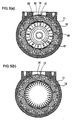
- the sector members 56 constituting the vertical split cylindrical body 53 are split out in the radial outward directions, Accordingly, the sector members 56 push out the core components 14 of the stator core 12, and the core components 14 are pressed on the circular internal surface of the motor housing 11, as illustrated In Figure 5 (B).
- each on the sector members 56 presses out a corresponding one of the core components 14.
- each of the sector members 56 is pressed at the center thereon in the circumferential direction, so that it is pressed on the circular internal surface of the motor housing 11 without being inclined.
- the sector members 56 are guided in the radial directions through the sliding engagement of the guide groove 60 with the guide pins 61 and can press the corresponding core components stably.
- the core components 14 are closely fit in the circular internal surface of the motor housing 11 to be positioned thereat.
- the positioning pin 66 is in engagement with the core component 14 with a certain play and hence, does not impede the radial outward displacement of that core component 14.
- the core components 14 come to join each another to make the stator core 12 like one body. Then, the movable table 40 is allowed to begin downward movement. With this downward movement, the amount through which the straight-motion shaft 51 has been withdrawn relative to the vertical split cylindrical body 53 is gradually reduced. This enables the tapered sleeve 54 to retract upward thanks to the resilient forces of the return spring 68 and the O-rings 59. Further, as the movable table 40 is moved down further, the cross bar 78 departs from the bar stops 79. This enables the vertical split cylindrical body 53 to be squeezed up to the state of a minimum diameter thereof. As a consequence, the vertical split cylindrical body 53 is turned to the state that it has a sufficient play of clearance with respect to the internal surface of the stator core 12 and therefore, is smoothly drawn out therefrom downward thereby to return the movable table 40 to the initial position.
- the motor housing 11 is removed from the housing fixing portion 35. After the temperature of the motor housing 11 goes down to the ambient temperature, a rotor 16 shown in Figure 1, bearings not show and the like are assembled to the motor housing 11, and the opposite ends of the same are closed by end cap members or the like, whereby the motor 10 is completed.
- the core components 14 are pressed on and positioned at the circular internal surface of the motor housing 11 in the course that the motor housing 11 contracts thermally, so that it does not occur that the core components 14 would be displaced when assembled, as is true in the case of the prior art. Therefore, the internal surface of the core components 14 so assembled becomes a circular shape which precisely coincide with that of the motor housing 11 in a complete coaxial alignment therewith, so that the accuracy in assembling of the core components 14 can be heightened in comparison with that in the prior art.
- motor housing 11 Is described as cylindrical, the external surface thereof may be square or polygonal.
- mechanism for actuating the straight-motion shaft 51 utilizes engagement of the cross bar 78 with the bar stops 79, that mechanism may be replaced by a solenoid operated device, a motor-operated device or the like.
- a cylindrical stator core circumferentially dividable to plural core components is inserted into a circular internal surfaced a motor housing.
- the motor housing is heated to be expanded thermally thereby enlarge the circular Internal surface thereof.
- the stator core Is fit over the external surface of an insertion guide head of a generally cylindrical shape, and the insertion guide head Is moved upward toward the thermally expanded motor housing secured on a fixed table to Insert the stator core inside the motor housing.
- a pressing mechanism incorporated In the Insertion guide head is operated to press the plural core components on the circular internal surface of the motor housing.
- the motor housing Is contracted as the temperature thereof goes down, whereby the plural core components are secured such that each of core components is pried at lateral surfaces thereof on the next core components In the circumferential direction as a result of being pressed by the circular internal surface of the motor housing.
Landscapes
- Engineering & Computer Science (AREA)
- Manufacturing & Machinery (AREA)
- Power Engineering (AREA)
- Manufacture Of Motors, Generators (AREA)
- Iron Core Of Rotating Electric Machines (AREA)
Abstract
Description
Claims (14)
- A method of manufacturing an electric motor by fitting a cylindrical stator core circumferentially dividable to plural core components, into a circular internal surface of a motor housing, said method comprising the steps of:thermally expanding said motor housing;inserting said stator core inside said thermally expanded motor housing; andthermally contracting said motor housing with said core components being kept pressed on said circular internal surface of said motor housing.
- A method as set forth in Claim 1, further including the step of:expanding said core components radially outward within said thermally expanded motor housing thereby to press said core components on said circular internal surface of said motor housing prior to the step of said thermally contracting said housing.
- A method as set forth in Claim 1, wherein the step of inserting said stator core includes temporarily holding said stator core with a ring being fit over the external surface of said stator core until at least a part of said stator core is fit in said circular internal surface of said motor housing.
- A method as set forth in Claim 1, wherein the step of inserting said stator core comprises the sub-steps of:temporarily holding said stator core with a ring being fit over the external surface of said stator core at an intermediate position in the axial direction thereof;inserting said stator core held with said ring into said circular internal surface of said motor housing by axially moving said stator core until said ring is brought into abutting engagement with a stationary part; andcompletely inserting said stator core into said circular internal surface by further axially moving said stator core thereby to make said stator core leave said ring engaged with said stationary part.
- A method as set forth in Claim 1, wherein said plural core components comprise plural sector members which complete an annular body when assembled to make each of said sector members closely contact at lateral surfaces with other members next thereto, and wherein each of said core components is positioned to be sandwiched between two core components next thereto at circumferentially opposite sides when the external surface thereof is pressed by said motor housing which is thermally contracted to a smaller diameter as time goes.
- A method as set forth in Claim 5, wherein each of said plural core components is formed with a coil retaining slot at each of both lateral surfaces over the entire length thereof, and wherein an electric wire Is wound around each of said core components to be retained within said coil retaining slots before said stator core is inserted inside said thermally expanded motor housing.
- An apparatus for manufacturing an electric motor by fitting a cylindrical stator core circumferentially dividable to plural core components, into a circular internal surface of a motor housing, said apparatus including:a pressing mechanism for pressing said core components from the inside of said stator core on said circular internal surface of said motor housing having been thermally expanded.
- An apparatus as set forth in Claim 7, wherein said pressing mechanism comprises:a vertical split cylindrical body circumferentially dividable to plural sector members and adapted to be inserted inside said stator core;a tapered shaft adapted to be thrusted inside said vertical split cylindrical body for expanding said vertical split cylindrical body in radially outward direction; andresilient means for urging said tapered shaft to be thrusted into said vertical split cylindrical body.
- An apparatus as set forth in Claim 8, wherein said pressing mechanism further comprises:adjusting means displaceable between first and second positions for varying the deformation amount of said resilient means;an annular resilient member for urging said vertical split cylindrical body to be squeezed in radial inward direction; and wherein:said tapered shaft cooperates with said adjusting means for expanding said vertical split cylindrical body against said annular resilient member in the radial outward direction when said adjusting means is located at said first position and for allowing said vertical split cylindrical body to be squeezed by means of the resilient force of said annular resilient member so that said vertical split cylindrical body so squeezed has a sufficient play of clearance within said stator core when said adjusting means is located at said second position.
- An apparatus as set forth in Claim 9, wherein said pressing mechanism further comprises:a base portion provided to face one end of said vertical split cylindrical body;a guide groove formed on either one of said base portion and said one end of each sector member and extending in radially outward direction from the axis of said vertical split cylindrical body, and;a guided member provided on the other of said base portion and said one end of each sector member and movable along said guide groove.
- An apparatus as set forth in Claim 9, wherein said pressing mechanism further comprises:a phase securing portion engageable with a part of said stator core fit over the external surface of said vertical split cylindrical body for positioning said stator core not to rotate relative to said vertical split cylindrical body while allowing said core components to displace in the radial direction.
- An apparatus as set forth in Claim 9, wherein said sector members and said core components are the same in number and wherein said phase securing portion secures the phase of said stator core so that each of said sector members is able to press a corresponding one of said core components.
- An apparatus as set forth in Claim 7, further comprising:a fixed table having a housing fixing portion for removably securing said motor housing at one axial end thereof with said motor housing being directed in the vertical direction;a movable table provided under said fixed table and connected thereto for upward movement toward said fixed table and downward movement away therefrom;a support member provided on said movable table in axial alignment with said motor housing on said fixed table;an insertion guide head of a generally cylindrical shape coaxially mounted on the upper end of said support member and adapted to removably mount said stator core thereon with said stator core being fit over the external surface thereof:said pressing mechanism being incorporated in said insertion guide head;a feed device for feeding said movable table toward said fixed table until said insertion guide head holding said stator core on the external surface thereof is inserted inside said motor housing; andmeans for operating said pressing mechanism when said insertion guide head reaches a predetermined axial position within said motor housing.
- An apparatus as set forth in Claim 13, wherein said means for operating said pressing mechanism comprises;a relay shaft mechanically connected at the upper end thereof to said pressing mechanism;a cross bar connected to the lower end of said relay shaft;resilient means for urging said relay shaft to an upward end position thereby to keep said pressing mechanism inoperative; andbar stop means provided stationarily for being brought into engagement with said cross bar thereby to bring said pressing mechanism into operation against said resilient means when said insertion guide head reaches said predetermined axial position within said motor housing.
Applications Claiming Priority (2)
| Application Number | Priority Date | Filing Date | Title |
|---|---|---|---|
| JP2002150162 | 2002-05-24 | ||
| JP2002150162A JP3932177B2 (en) | 2002-05-24 | 2002-05-24 | Motor manufacturing equipment |
Publications (3)
| Publication Number | Publication Date |
|---|---|
| EP1367699A2 true EP1367699A2 (en) | 2003-12-03 |
| EP1367699A3 EP1367699A3 (en) | 2003-12-10 |
| EP1367699B1 EP1367699B1 (en) | 2006-06-21 |
Family
ID=29417134
Family Applications (1)
| Application Number | Title | Priority Date | Filing Date |
|---|---|---|---|
| EP03011769A Expired - Lifetime EP1367699B1 (en) | 2002-05-24 | 2003-05-23 | Method and apparatus for manufacturing electric motor |
Country Status (4)
| Country | Link |
|---|---|
| US (1) | US7225525B2 (en) |
| EP (1) | EP1367699B1 (en) |
| JP (1) | JP3932177B2 (en) |
| DE (1) | DE60306263T2 (en) |
Cited By (17)
| Publication number | Priority date | Publication date | Assignee | Title |
|---|---|---|---|---|
| WO2006041776A1 (en) * | 2004-10-04 | 2006-04-20 | Emerson Electric Co. | Electric machines and methods related to assembling electric machines |
| US7105976B2 (en) | 2004-10-04 | 2006-09-12 | Emerson Electric Co. | Electric machines and methods related to assembling electric machines |
| US7281313B2 (en) | 2004-10-04 | 2007-10-16 | Emerson Electric Co. | Electric machines and methods related to assembling electric machines |
| US7408282B2 (en) | 2004-10-04 | 2008-08-05 | Emerson Electric Co. | End shields and stators and related methods of assembly |
| US7451543B2 (en) | 2004-10-04 | 2008-11-18 | Emerson Electric Co. | Methods of securing a bearing with an adaptor sleeve within an opening of a housing |
| US7581307B2 (en) | 2004-10-04 | 2009-09-01 | Emerson Electric Co. | Method of making an electric machine having an electronics mount secured by an interference fit |
| US20130162062A1 (en) * | 2011-12-22 | 2013-06-27 | Black & Decker Inc. | Stator assembly having end cap with polarity keying feature for a power tool |
| CN103855821A (en) * | 2012-12-04 | 2014-06-11 | 发那科株式会社 | Stator of electric motor |
| EP1976094A4 (en) * | 2006-01-16 | 2017-03-08 | Toyota Jidosha Kabushiki Kaisha | Rotary motor core, and rotary motor |
| CN109450197A (en) * | 2018-12-13 | 2019-03-08 | 温岭市微米自动化设备有限公司 | Shield the automatic press mounting equipment of pump motor |
| CN113119025A (en) * | 2021-05-18 | 2021-07-16 | 深圳市凯昇科技有限公司 | Fixed rotary seat |
| CN113231816A (en) * | 2021-05-17 | 2021-08-10 | 和氏工业技术股份有限公司 | Compressor main shaft press-fitting equipment |
| CN114260388A (en) * | 2021-12-20 | 2022-04-01 | 浙江中车尚驰电气有限公司 | Flat wire stator end twisting device and method thereof |
| CN114362463A (en) * | 2022-01-17 | 2022-04-15 | 浙江伟康电机有限公司 | Motor assembly all-in-one machine |
| CN116275945A (en) * | 2023-03-17 | 2023-06-23 | 上海纳铁福传动系统有限公司 | Clamp ring automatic assembly device |
| CN118826397A (en) * | 2024-09-18 | 2024-10-22 | 温州职业技术学院 | A kind of motor stator core production and processing device and process |
| CN119347317A (en) * | 2024-12-27 | 2025-01-24 | 安徽金易智能机器有限公司 | A motor stator casing integrated processing device and use method |
Families Citing this family (32)
| Publication number | Priority date | Publication date | Assignee | Title |
|---|---|---|---|---|
| WO2005048435A1 (en) * | 2003-11-13 | 2005-05-26 | Sew-Eurodrive Gmbh & Co. Kg | Compact drive |
| JP4926456B2 (en) * | 2005-11-11 | 2012-05-09 | アスモ株式会社 | Stator manufacturing method |
| JP4600580B2 (en) * | 2008-04-21 | 2010-12-15 | 株式会社デンソー | Stator coil manufacturing method |
| US8528192B2 (en) * | 2008-06-30 | 2013-09-10 | General Electric Company | Fixture for removing slip rings from rotating electrical machinery |
| JP5217704B2 (en) * | 2008-07-07 | 2013-06-19 | 株式会社デンソー | Stator manufacturing apparatus and stator manufacturing method for rotating electrical machine |
| JP2010074905A (en) * | 2008-09-17 | 2010-04-02 | Sanyo Electric Co Ltd | Mold motor and electric vehicle |
| JP5277860B2 (en) * | 2008-10-21 | 2013-08-28 | トヨタ自動車株式会社 | Stator core manufacturing method and stator core manufacturing apparatus |
| JP5556197B2 (en) * | 2010-01-29 | 2014-07-23 | アイシン精機株式会社 | Shrink-fitting device, shrink-fitting method and shrink-fitting fastener |
| JP5723169B2 (en) * | 2011-02-03 | 2015-05-27 | アスモ株式会社 | Stator manufacturing method and stator manufacturing apparatus |
| US8479378B1 (en) | 2012-02-09 | 2013-07-09 | John Pairaktaridis | Methods of manufacturing a stator core for a brushless motor |
| JP6084040B2 (en) * | 2013-01-10 | 2017-02-22 | アスモ株式会社 | Stator manufacturing method |
| US9806566B2 (en) | 2012-08-30 | 2017-10-31 | Asmo Co., Ltd. | Brushless motor, stator, stator manufacturing method and brushless motor manufacturing method |
| JP6237144B2 (en) * | 2013-11-15 | 2017-11-29 | アイシン精機株式会社 | Rotating electric machine |
| US10468937B2 (en) * | 2014-12-01 | 2019-11-05 | Tesla, Inc. | Cantilever stator |
| JP6579685B2 (en) * | 2015-03-02 | 2019-09-25 | Nittoku株式会社 | Stator manufacturing method and manufacturing apparatus thereof |
| CN106329844A (en) * | 2015-06-25 | 2017-01-11 | 天津市江源塑胶制品有限公司 | Outer-winding inner-rotor motor stator iron core fixing device |
| CN105945546B (en) * | 2016-04-28 | 2017-12-26 | 浙江厚达智能科技股份有限公司 | The transfer charging basket of motor stator terminal insertion machine |
| CN106712398B (en) * | 2016-12-25 | 2023-05-12 | 重庆市爱华机电有限公司双福分公司 | A kind of motor bearing pressing equipment |
| CN107453564B (en) * | 2017-09-20 | 2024-02-09 | 安徽美芝制冷设备有限公司 | Shaping tool and shaping method for stator core |
| JP6590904B2 (en) * | 2017-12-21 | 2019-10-16 | 三菱電機株式会社 | Compressor manufacturing apparatus and compressor manufacturing method |
| CN108063529B (en) * | 2017-12-29 | 2022-12-13 | 山东双林新能源科技有限公司 | Efficient motor stator assembling and disassembling device |
| CN111193365B (en) * | 2019-12-19 | 2021-11-05 | 江苏久知电机股份有限公司 | Motor stator module press-in machine |
| CN112910193B (en) * | 2021-02-26 | 2025-07-18 | 捷云智能装备(苏州)有限公司 | Integral press-fitting mechanism and stacking system for asynchronous motor |
| CN112994377B (en) * | 2021-04-29 | 2022-03-29 | 江苏晨光涂料有限公司 | A hot-pressing device for processing self-adhesive coating of stator core |
| CN115229460B (en) * | 2022-06-20 | 2023-10-10 | 满洲里达赉湖热电有限公司 | A water pump vertical assembly device |
| CN115401650A (en) * | 2022-09-30 | 2022-11-29 | 苏州奥布斯自动化科技有限公司 | Press fitting equipment |
| CN115489100B (en) * | 2022-10-26 | 2024-11-01 | 安徽汉普斯精密传动有限公司 | Speed reducer encapsulation gum cover assembly device |
| CN115833506B (en) * | 2023-02-23 | 2023-04-14 | 北京精雕科技集团有限公司 | Spindle mechanism for winding machine and winding machine |
| JPWO2025004600A1 (en) * | 2023-06-29 | 2025-01-02 | ||
| CN116900662B (en) * | 2023-08-01 | 2025-03-18 | 巢湖宜安云海科技有限公司 | A motor housing inlaid steel sleeve machining device and its machining process |
| CN117748851B (en) * | 2023-12-20 | 2024-06-18 | 广东长锦成智能制造有限公司 | Stator core assembly quality is used in brushless motor production |
| CN119865016B (en) * | 2025-02-07 | 2025-07-04 | 娄底市创微达电器有限公司 | DC brushless motor system of processing |
Family Cites Families (9)
| Publication number | Priority date | Publication date | Assignee | Title |
|---|---|---|---|---|
| DE930765C (en) | 1953-03-01 | 1955-07-25 | Heinrich Lenz | Device for pulling out and pressing in the stator winding-bearing laminated core of electrical machines, in particular of motors for electric hand drills and grinders and. like |
| DE4018089A1 (en) * | 1990-06-06 | 1991-12-12 | Bosch Gmbh Robert | METHOD FOR PRODUCING THE STAND OF AN ELECTRICAL MACHINE, PREFERABLY THREE-PHASE GENERATOR |
| JPH06245444A (en) | 1993-02-15 | 1994-09-02 | Toyo Electric Mfg Co Ltd | Outer frame of coolant-type electric rotating machine and manufacture of the outer frame |
| JPH07163070A (en) * | 1993-12-07 | 1995-06-23 | Honda Motor Co Ltd | Method for manufacturing stator of electric motor and stator manufactured by the method |
| JP3432356B2 (en) * | 1996-05-13 | 2003-08-04 | 山洋電気株式会社 | Method of manufacturing split type stator for rotating electric machine |
| JP3904323B2 (en) | 1998-04-27 | 2007-04-11 | 本田技研工業株式会社 | Method and apparatus for assembling motor stator |
| JP3678102B2 (en) * | 2000-02-02 | 2005-08-03 | 株式会社日立製作所 | Electric motor |
| US6359355B1 (en) * | 2000-03-20 | 2002-03-19 | Emerson Electric Co. | Hot dropped shell and segmented stator tooth motor |
| JP2003052139A (en) * | 2001-08-07 | 2003-02-21 | Hitachi Ltd | Iron core, rotating electric machine using the same, and method of manufacturing the same |
-
2002
- 2002-05-24 JP JP2002150162A patent/JP3932177B2/en not_active Expired - Fee Related
-
2003
- 2003-05-23 EP EP03011769A patent/EP1367699B1/en not_active Expired - Lifetime
- 2003-05-23 US US10/443,749 patent/US7225525B2/en not_active Expired - Lifetime
- 2003-05-23 DE DE60306263T patent/DE60306263T2/en not_active Expired - Lifetime
Cited By (20)
| Publication number | Priority date | Publication date | Assignee | Title |
|---|---|---|---|---|
| WO2006041776A1 (en) * | 2004-10-04 | 2006-04-20 | Emerson Electric Co. | Electric machines and methods related to assembling electric machines |
| WO2006041775A3 (en) * | 2004-10-04 | 2006-07-06 | Emerson Electric Co | Electric machines and methods related to assembling electric machines |
| US7105976B2 (en) | 2004-10-04 | 2006-09-12 | Emerson Electric Co. | Electric machines and methods related to assembling electric machines |
| US7281313B2 (en) | 2004-10-04 | 2007-10-16 | Emerson Electric Co. | Electric machines and methods related to assembling electric machines |
| US7408282B2 (en) | 2004-10-04 | 2008-08-05 | Emerson Electric Co. | End shields and stators and related methods of assembly |
| US7451543B2 (en) | 2004-10-04 | 2008-11-18 | Emerson Electric Co. | Methods of securing a bearing with an adaptor sleeve within an opening of a housing |
| US7581307B2 (en) | 2004-10-04 | 2009-09-01 | Emerson Electric Co. | Method of making an electric machine having an electronics mount secured by an interference fit |
| EP1976094A4 (en) * | 2006-01-16 | 2017-03-08 | Toyota Jidosha Kabushiki Kaisha | Rotary motor core, and rotary motor |
| US20130162062A1 (en) * | 2011-12-22 | 2013-06-27 | Black & Decker Inc. | Stator assembly having end cap with polarity keying feature for a power tool |
| CN103855821A (en) * | 2012-12-04 | 2014-06-11 | 发那科株式会社 | Stator of electric motor |
| CN103855821B (en) * | 2012-12-04 | 2016-10-19 | 发那科株式会社 | The stator of motor |
| CN109450197A (en) * | 2018-12-13 | 2019-03-08 | 温岭市微米自动化设备有限公司 | Shield the automatic press mounting equipment of pump motor |
| CN113231816A (en) * | 2021-05-17 | 2021-08-10 | 和氏工业技术股份有限公司 | Compressor main shaft press-fitting equipment |
| CN113119025A (en) * | 2021-05-18 | 2021-07-16 | 深圳市凯昇科技有限公司 | Fixed rotary seat |
| CN114260388A (en) * | 2021-12-20 | 2022-04-01 | 浙江中车尚驰电气有限公司 | Flat wire stator end twisting device and method thereof |
| CN114260388B (en) * | 2021-12-20 | 2023-07-18 | 浙江中车尚驰电气有限公司 | Flat wire stator end part twisting device and method thereof |
| CN114362463A (en) * | 2022-01-17 | 2022-04-15 | 浙江伟康电机有限公司 | Motor assembly all-in-one machine |
| CN116275945A (en) * | 2023-03-17 | 2023-06-23 | 上海纳铁福传动系统有限公司 | Clamp ring automatic assembly device |
| CN118826397A (en) * | 2024-09-18 | 2024-10-22 | 温州职业技术学院 | A kind of motor stator core production and processing device and process |
| CN119347317A (en) * | 2024-12-27 | 2025-01-24 | 安徽金易智能机器有限公司 | A motor stator casing integrated processing device and use method |
Also Published As
| Publication number | Publication date |
|---|---|
| JP3932177B2 (en) | 2007-06-20 |
| DE60306263D1 (en) | 2006-08-03 |
| EP1367699B1 (en) | 2006-06-21 |
| EP1367699A3 (en) | 2003-12-10 |
| JP2003348801A (en) | 2003-12-05 |
| US20050125987A1 (en) | 2005-06-16 |
| US7225525B2 (en) | 2007-06-05 |
| DE60306263T2 (en) | 2007-04-26 |
Similar Documents
| Publication | Publication Date | Title |
|---|---|---|
| EP1367699B1 (en) | Method and apparatus for manufacturing electric motor | |
| CN107408874A (en) | Stator manufacturing device and manufacturing method thereof | |
| WO2013137350A1 (en) | Stator coil shaping method and stator coil shaping apparatus | |
| US7886426B2 (en) | Stator manufacturing apparatus | |
| JP2014158413A (en) | Coil terminal molding device and coil terminal molding method | |
| US5249090A (en) | Disk store with device for fixing the disk pack on its hub such that it can be removed | |
| US6510603B1 (en) | Rotor production method including assembling a slot insulator and coil trunk into a set prior to insertion into an armature core | |
| CN112311170B (en) | Crown placement and engagement apparatus and crown placement and engagement method | |
| CN113054766A (en) | Motor core, positioning device for iron core riveting and iron core riveting die | |
| US4476625A (en) | Apparatus of inserting wedges into the slots of a magnetic core | |
| JP2011193699A (en) | Pallet for assembling rotary electric machine and rotary electric machine assembling device | |
| CN115431013A (en) | Turbofan engine case press-mounting device | |
| US4777717A (en) | Method for manufacturing a magnet-type motor yoke assembly | |
| JP2014187840A (en) | Stator core manufacturing method | |
| US6006416A (en) | Method of mounting permanent magnet | |
| US4955130A (en) | Feeder blade replacement apparatus for coil inserter tooling | |
| CN118451640A (en) | Method and device for manufacturing rotor for rotating electrical machine | |
| JP2011160510A (en) | Shrinkage fitting device, shrinkage fitting method, and shrinkage fitting sintered compact | |
| CN215835209U (en) | Motor core, positioning device for iron core riveting and iron core riveting die | |
| JP7608233B2 (en) | Stator assembly device and manufacturing method | |
| EP1388922B1 (en) | Rotor, Manufacturing Method of the Rotor and Motor using the Rotor | |
| JP4262377B2 (en) | Stator winding device | |
| JP2004064819A (en) | Armature coil forming apparatus and method | |
| JP2865562B2 (en) | Method and apparatus for coating rotor magnet | |
| JPS62102930A (en) | Inserting device for cam shaft |
Legal Events
| Date | Code | Title | Description |
|---|---|---|---|
| PUAI | Public reference made under article 153(3) epc to a published international application that has entered the european phase |
Free format text: ORIGINAL CODE: 0009012 |
|
| PUAL | Search report despatched |
Free format text: ORIGINAL CODE: 0009013 |
|
| AK | Designated contracting states |
Kind code of ref document: A2 Designated state(s): AT BE BG CH CY CZ DE DK EE ES FI FR GB GR HU IE IT LI LU MC NL PT RO SE SI SK TR |
|
| AX | Request for extension of the european patent |
Extension state: AL LT LV MK |
|
| AK | Designated contracting states |
Kind code of ref document: A3 Designated state(s): AT BE BG CH CY CZ DE DK EE ES FI FR GB GR HU IE IT LI LU MC NL PT RO SE SI SK TR |
|
| AX | Request for extension of the european patent |
Extension state: AL LT LV MK |
|
| 17P | Request for examination filed |
Effective date: 20040427 |
|
| 17Q | First examination report despatched |
Effective date: 20040603 |
|
| AKX | Designation fees paid |
Designated state(s): DE FR GB |
|
| GRAP | Despatch of communication of intention to grant a patent |
Free format text: ORIGINAL CODE: EPIDOSNIGR1 |
|
| GRAS | Grant fee paid |
Free format text: ORIGINAL CODE: EPIDOSNIGR3 |
|
| GRAA | (expected) grant |
Free format text: ORIGINAL CODE: 0009210 |
|
| AK | Designated contracting states |
Kind code of ref document: B1 Designated state(s): DE FR GB |
|
| REG | Reference to a national code |
Ref country code: GB Ref legal event code: FG4D |
|
| REF | Corresponds to: |
Ref document number: 60306263 Country of ref document: DE Date of ref document: 20060803 Kind code of ref document: P |
|
| RAP2 | Party data changed (patent owner data changed or rights of a patent transferred) |
Owner name: JTEKT CORPORATION |
|
| RIN2 | Information on inventor provided after grant (corrected) |
Inventor name: TANAKA, YOSHIHIRO Inventor name: MATSUYA, YOSHIHIRO Inventor name: YAMASAKI, TSUYOSHI Inventor name: TATEBE, KATSUHIKO Inventor name: YAMAMOTO, TETSUJI Inventor name: HIRAMITSU, AKIRA |
|
| ET | Fr: translation filed | ||
| PLBE | No opposition filed within time limit |
Free format text: ORIGINAL CODE: 0009261 |
|
| STAA | Information on the status of an ep patent application or granted ep patent |
Free format text: STATUS: NO OPPOSITION FILED WITHIN TIME LIMIT |
|
| 26N | No opposition filed |
Effective date: 20070322 |
|
| REG | Reference to a national code |
Ref country code: FR Ref legal event code: PLFP Year of fee payment: 14 |
|
| REG | Reference to a national code |
Ref country code: FR Ref legal event code: PLFP Year of fee payment: 15 |
|
| REG | Reference to a national code |
Ref country code: FR Ref legal event code: PLFP Year of fee payment: 16 |
|
| PGFP | Annual fee paid to national office [announced via postgrant information from national office to epo] |
Ref country code: DE Payment date: 20210427 Year of fee payment: 19 Ref country code: FR Payment date: 20210412 Year of fee payment: 19 |
|
| PGFP | Annual fee paid to national office [announced via postgrant information from national office to epo] |
Ref country code: GB Payment date: 20210429 Year of fee payment: 19 |
|
| REG | Reference to a national code |
Ref country code: DE Ref legal event code: R119 Ref document number: 60306263 Country of ref document: DE |
|
| GBPC | Gb: european patent ceased through non-payment of renewal fee |
Effective date: 20220523 |
|
| PG25 | Lapsed in a contracting state [announced via postgrant information from national office to epo] |
Ref country code: FR Free format text: LAPSE BECAUSE OF NON-PAYMENT OF DUE FEES Effective date: 20220531 |
|
| PG25 | Lapsed in a contracting state [announced via postgrant information from national office to epo] |
Ref country code: GB Free format text: LAPSE BECAUSE OF NON-PAYMENT OF DUE FEES Effective date: 20220523 Ref country code: DE Free format text: LAPSE BECAUSE OF NON-PAYMENT OF DUE FEES Effective date: 20221201 |