FIELD OF THE INVENTION
The present invention relates to a magnetic recording
medium capable of high density recording excellent in
electromagnetic characteristics and running durability.
BACKGROUND OF THE INVENTION
Magnetic recording media are widely used as the recording
media of all sorts of data, such as sounds, images and characters.
In recent years, there arises a need for high density recording
corresponding to the improvements of data-recording capacity
and transfer speed, so that a magnetic recording medium having
high electromagnetic characteristics is required. Further,
the reliability at the time when data are repeatedly used and
saved is also required at the same time. Accordingly, good
running durability is also required of a magnetic recording
medium in addition to excellent electromagnetic characteristics.
For that sake, particularly in tape media, the improvement
of running durability is contrived by providing a backing layer.
To improve running durability by a backing layer, providing
pimples on the surface of a support, or roughening the surface
of a backing layer by adding coarse carbon having a particle
size of 0.1 µm or more have been tried. However, if the surface
of a backing layer is roughened by these methods, when a magnetic
recording tape is wound onto ahub forpreservation or processing,
the backing layer and a magnetic layer are tightly pressed
and the pimples of the backing layer are impressed on the magnetic
layer, i.e., so-called "setoff", is caused. As a result, a
drawback such that electromagnetic characteristics are
deteriorated arises. For solving such "setoff", it is tried
to smooth the surface of a backing layer surface. However,
when the surface of a backing layer is smoothed, the friction
coefficient against the guides of a tape drive and the like
becomes great and running stability lowers. Therefore, it
is tried to add a relatively large amount of lubricant to a
backing layer for reducing the friction coefficient. However,
the viscosity of the backing layer surface increases when a
great amount of lubricant is used, which causes other problems
such that the lubricant makes the guide dirty, or a magnetic
layer adheres to the backing layer when the medium is preserved
for a long period of time in a wound state. Thus, it is necessary
to further improve a backing layer for manufacturing a magnetic
recording tape excellent in electromagnetic characteristics
and running stability.
In tapes for computer storage in recent years, it is
required to further lessen the thickness of a tape at large
for increasing the capacity of a magnetic recording medium.
For thinning the thickness of a magnetic recording tape, it
has been performed to decrease the thickness of a flexible
support, or decrease the thickness of a nonmagnetic layer
provided between a flexible support and a magnetic layer of
a coating type magnetic recording tape. However, running
durability lowers if the thickness of a flexible support is
thinned to less than a certain range, and if a nonmagnetic
layer is thinned, output lowers, an error rate increases and
dropout rises. A backing layer cannot be excluded for
maintaining a good running property. Further, when the
thickness of a backing layer is thinned, the adhesion strength
between the backing layer and the support lowers, as a result,
the backing layer peels off during running, or the pimples
on the surface of the backing layer are impressed onto the
magnetic layer, so that noise increases and S/N ratio decreases.
An aramid base is used as a flexible support in a thinner
tape, but dropping out and peeling off at the edge of a backing
layer during running are conspicuous in an aramidbase as compared
with conventionally used polyester bases, e.g., polyethylene
terephthalate (PET) and polyethylene naphthalate (PEN).
Further, the strength in the width direction of a thin magnetic
recording tape is maintained by increasing the Young's modulus
in the width direction of a flexible support to thereby ensure
running durability, but when a broad magnetic recording tape
is slit into a prescribed width, the end face of a backing
layer (i.e., an end face newly formed by slitting) drops out.
A conventional magnetic recording tape in which the
improvement of electromagnetic characteristics has been
contrived by improving so-called setoff by smoothing a backing
layer is accompanied by problems such that the friction
coefficient of the backing layer increases during repeating
running or the backing layer is scratched. To cope with these
problems, it is disclosed in JP-A-11-259851 (the term "JP-A"
as used herein means an "unexamined published Japanese patent
application") to add to a backing layer a mixture of particulate
titanium oxide and carbon black as a main ingredient, a binder,
fatty acid and fatty acid ester as a lubricant, and alumina
as an abrasive. However, by the addition of a lubricant, the
binder used in the backing layer is plasticized and the backing
layer is adhered to the magnetic layer when themedium is preserved
for a long time under high temperature . When a binder containing,
in particular, a chlorine, e.g., a vinyl chloride resin, is
used, the hydrolysis of the lubricant and the binder is
accelerated, so that the adhesion becomes conspicuous.
Thus, the prior art techniques cannot yet provide a
magnetic recording tape having satisfactory electromagnetic
characteristics and running durability. In particular, in
these days of being required of thinning of a magnetic recording
tape at large, a satisfactory a magnetic recording tape is
not provided yet, although a magnetic recording tape excellent
in electromagnetic characteristics and running durability is
required.
SUMMARY OF THE INVENTION
An object of the present invention is to solve the problems
of prior art techniques and provide a magnetic recording medium
which is capable of high density recording, hardly generates
the setoff of a backing layer to a magnetic layer, exhibits
good electromagnetic characteristics, storage stability and
running durability.
As a result of eager investigation for achieving the
above object, the present inventors have found that a magnetic
recording medium having a smooth backing layer surface, hardly
generating the setoff, and excellent in electromagnetic
characteristics, running durability and storage stability can
be achieved by a magnetic recording medium comprising a flexible
support having a magnetic layer on one side and a backing layer
on the opposite side of the support, wherein the backing layer
contains nonmagnetic inorganic particle A having an acicular
ratio of from 3 to 15 and carbon black B having an average
particle size of from 10 to 50 nm in the ratio of A/B = from
60/40 to 90/10 (mass ratio (weight ratio)), and the glass
transition point Tg of the backing layer is from 80 to 140°C.
The preferred embodiments of the present invention are
as follows.
In the first place, durability can be further improved
without deteriorating setoff by adding to the backing layer
an abrasive having a Moh's hardness of 9 or more and an average
particle size of from 10 to 40% of the backing layer thickness.
In the second place, storage stability and smoothness can
be improved simultaneously by using, as a binder, polyurethane
containing no chlorine and having a Tg of from 80 to 140°C
obtained by the reaction of diol having a cyclic structure
to achieve a Tg of from 80 to 140°C, diol containing an ether
group, and organic diisocyanate.
DETAILED DESCRIPTION OF THE INVENTION
The thickness of a backing layer is generally set at
1 µm or less for making a tape thickness thin, but the effect
of calendering treatment is small with a thin layer and a smooth
surface is obtained with difficulty. Film-forming becomes
further difficult when a coating layer having a high Tg is
used for preventing adhesion due to preservation.
Accordingly, in the invention, by mixing nonmagnetic
inorganic particle A having a specific acicular ratio, i.e.,
an acicular ratio of from 3 to 15 (hereinafter referred to
as acicular nonmagnetic inorganic particle A) , and carbon black
B having an average particle size of from 10 to 50 nm in the
ratio of A/B = from 60/40 to 90/10 (mass ratio), the layer
formability is improved, thereby smoothness, durability and
storage stability are improved at the same time.
The magnetic recording medium of the invention widely
includes those comprising a flexible support having a magnetic
layer on one side and a backing layer on the opposite side
of the support. Accordingly, magnetic recording media having
layers other than a magnetic layer and a backing layer are
also included in the magnetic recording medium of the invention.
For example, they can have a nonmagnetic layer containing
nonmagnetic powder, a soft magnetic layer containing soft
magnetic powder, a second magnetic layer, a cushioning layer,
an overcoat layer, an adhesion layer and a protective layer.
These layers can be provided at appropriate places so that
their functions can be effectively exhibited. A magnetic
recording medium having a nonmagnetic layer containing
nonmagnetic inorganic powder and a binder between a flexible
support and a magnetic layer is preferred as the magnetic
recording medium of the invention. A magnetic layer can have
a layer thickness of, for example, generally from 0.01 to 1 µm,
preferably from 0.03 to 0.5 µm, and more preferably from 0.03
to 0.2 µm, and a nonmagnetic layer can have a layer thickness
of generally from 0.5 to 3 µm, and preferably from 0.8 to 3 µm.
The layer thickness of a nonmagnetic layer is preferably thicker
than the thickness of a magnetic layer. A magnetic recording
medium having two magnetic layers is also preferably used in
the invention. In this case, the upper layer thickness may
be generally from 0.2 to 2 µm, preferably from 0.2 to 1.5 µm,
and the lower layer thickness may be generally from 0.8 to
3 µm. When a magnetic layer comprises a single layer, the
layer thickness of the magnetic layer is generally from 0.1
to 5 µm, preferably from 0.1 to 3 µm, and more preferably from
0.1 to 1.5 µm. When a soft magnetic layer is provided between
a flexible support and a magnetic layer, the magnetic layer
thickness may be generally, e.g., from 0.03 to 1 µm, preferably
from 0.05 to 0.5 µm, and the soft magnetic layer thickness
may be generally from 0.8 to 3 µm. With respect to the magnetic
layer, not only a so-called coating type magnetic layer
containing ferromagnetic powder dispersed in a binder but a
thin film type magnetic layer formed by vacuum evaporation
or sputtering may be used. The thin film type magnetic layer
has a layer thickness of generally from 0.05 to 0.3 µm, and
preferably from 0.1 to 0.2 µm. The thickness of a backing
layer formed in the magnetic recording medium of the invention
is generally from 0.05 to 1.0 µm, preferably from 0.1 to 0.8 µm,
and more preferably from 0.2 to 0.6 µm.
Nonmagnetic inorganic particle A having an acicular
ratio of from 3 to 15 is used in a backing layer of the magnetic
recording medium of the invention. The acicular ratio is
preferably from 4 to 10. The acicular ratio in the invention
is a value obtained by dividing the long axis length of a particle
by the short axis length. The short axis length means the
maximum length of the orthogonal secion of the long axis.
The long axis length is from 30 to 500 nm, preferably from
50 to 300 nm, and more preferably from 50 to 200 nm. When
the acicular ratio is smaller than 3, the voids in the coated
layer decrease and the film-forming effect by calendering is
damaged, while when it is greater than 15, surface roughness
increases and setoff is deteriorated. As the nonmagnetic
powders, metallic oxides, e.g., titanium oxide, alpha-iron
oxide, SiO2, SnO2, WO3, Al2O3, ZrO2 and ZnO, BaSO4, salts, e.g.,
barium titanate, and metallic whiskers of, e.g., Cu and Al
can be used. Oxides which are excellent in chemical
stabilization are preferably used as the nonmagnetic powders.
These nonmagnetic powders can be used as mixture.
Carbon black B having an average particle size of from
10 to 50 nm, preferably from 10 to 40 nm, is used in the backing
layer of the magnetic recording medium of the present invention
as the mixture with the above acicular nonmagnetic inorganic
particle A in the mass ratio of A/B of from 60/40 to 90/10,
preferably 70/30 to 90/10. An average particle size here means
the arithmetic mean of the particle sizes of independent
particles free of agglomeration. When the average particle
size of carbon black B is greater than 50 nm, voids decrease
due to the undevelopment of structure and the film-forming
effect by calendering is damaged, and electric conduction also
lowers. When the average particle size is smaller than 10 nm,
severe agglomeration occurs and pimples are formed on the backing
layer surface (hereinafter also referred to as back surface)
When the ratio of A is higher than the above mixing ratio,
the film-forming effect is damaged and a problem of electrostatic
charge arises, and when the ratio of A is lower than the above
mixing ratio, dispersibility deteriorates.
Further, it is preferred to add carbon black having
an average particle size of 80 nm or more to a backing layer
as a solid lubricant. The addition amount of such carbon black
is from 0.1 to 10 mass parts (parts by weight) when the total
amount of A and B is taken as 100 mass parts, preferably from
0.3 to 5 mass parts. If too large an amount is used, pimples
on the back surface increase and setoff becomes conspicuous.
Carbon blacks have pH of from 2 to 10, a water content
of from 0.1 to 10%, and a tap density of from 0.1 to 1 g/ml.
Carbon blacks having an average particle size of from 10 to
50 nm have a specific surface area of generally from 100 to
500 m2/g, preferably from 150 to 400 m2/g, and DBF oil absorption
of generally from 20 to 400 ml/100 g, and preferably from 30
to 200 ml/100 g. The specific examples of carbon blacks having
an average particle size of from 10 to 50 nm for use in the
present invention include BLACK PEARL S2000, S1300, S1000,
S900, S800, S880 and S700, and VULCAN XC-72 (manufactured by
Cabot Co., Ltd.), #3050B, #3150B, #3250B, #3750B, #3950B, #950,
#650B, #970B and #850B, and MA-600 (manufactured by Mitsubishi
Kasei Corp.), CONDUCTEX SC, RAVEN 8800, 8000, 7000, 5750, 5250,
3500, 2100, 2000, 1800, 1500, 1255 and 1250 (manufactured by
Columbia Carbon Co., Ltd.), and Ketjen Black EC (manufactured
by Akzo Co., Ltd.). Carbon blacks having an average particle
size of 80 nm or more have a specific surface area of generally
from 5 to 100 m2/g, preferably from 5 to 30 m2/g, and DBP oil
absorption of generally from 20 to 120 ml/100 g, and preferably
from 30 to 110 ml/100 g, and the specific examples include
#55, #50 and #30 (manufactured by Asahi Carbon Co., Ltd.),
RAVEN 450 and 430 (manufactured by Columbia Carbon Co. , Ltd.),
and THERMAX MT (manufactured by Cancarb Co., Ltd.).
As the binder for abacking layer of the present invention,
well-known thermoplastic resins, thermo-setting resins and
reactive type resins can be used. The examples of preferred
binders include cellulose resins not containing a chlorine,
e.g., nitrocellulose, a phenoxy resin and a polyurethane resin.
Of these resins, polyurethane resins having a Tg of from 80
to 140°C are more preferably used for improving storage stability.
Particularly preferred polyurethane resins are polyurethane
resins obtained by the reaction of diol and organic diisocyanate
and the diol comprises from 17 to 40 mass% (weight%) of short
chain diol having a cyclic structure based on the polyurethane,
and from 10 to 50 mass% of long chain diol having an ether
bond, and contains from 1.0 to 5.0 mol/g of the ether bond
in the long chain diol based on the polyurethane. The
polyurethane resin is described below.
The short chain diols have a molecular weight of from
50 to less than 500, more preferably from 100 to 300. The
specific examples of the short chain diols include aromatic
or alicyclic diol, e.g., cyclohexane-1,4-diol,
cyclohexane-1,4-dimethanol, bisphenol A, hydrogenated
bisphenol A, bisphenol S, bisphenol P, ethylene oxide adducts
of these short chain diols, propylene oxide adduct of these
short chain diols, cyclohexanedimethanol, and cyclohexanediol.
The long chain diols have a molecular weight of from 500 to
5,000. The specific examples of the long chain diols include
ethylene oxide adducts of bisphenol A and hydrogenated bisphenol
A, and propylene oxide adducts of bisphenol A and hydrogenated
bisphenol A, each having a molecular weight of from 500 to
5,000. The preferred short chain diol and long chain diol
are represented by the following formula (1) :
In the case of short chain diol, m and n are selected
so that the molecular weight of the short chain diol becomes
50 or more and less than 500, and generally m and n are from
0 to 3.
In the case of long chain diol, m and n are selected
so that the molecular weight of the long chain diol becomes
from 500 to 5,000, and generally m and n are from 3 to 24,
preferably from 3 to 20, and more preferably from 4 to 15.
When m and n are greater than 24, a backing layer softens and
running durability lowers.
X preferably represents a hydrogen atom or a methyl
group, and more preferably a methyl group. X's parenthesized
by m and n need not be the same and a hydrogen atom and a methyl
group may be mixed.
R represents the residue of bisphenol A or hydrogenated
bisphenol A. Of the short diols represented by formula (1),
bisphenol A, hydrogenated bisphenol A, ethylene oxide adducts
of bisphenol A and hydrogenated bisphenol A, and propylene
oxide adducts of bisphenol A and hydrogenated bisphenol A are
preferred.
The preferred long chain diols are diols having a
molecular weight of from 500 to 5,000 derived from bisphenol
A or hydrogenated bisphenol A, and particularly preferred long
chain diols are propylene oxide adducts of bisphenol A. The
short chain diol content is generally from 17 to 40 mass% based
on the polyurethane resin, and preferably from 20 to 30 mass%.
The long chain diol content is generally from 10 to 50 mass%,
and preferably from 30 to 40 mass%. The ether group in the
long chain diol unit is generally contained from 1.0 to 5.0
mmol/g in the polyurethane resin, and more preferably from
2.0 to 4.0 mmol/g. By using such a polyurethane resin as the
binder of a backing layer, more excellent adhesion to powders,
dispersibility and solubility in a solvent can be obtained.
Diols other than the above short chain and long chain
diols can be used in the present invention. Specifically,
aliphatic diol, e.g., ethylene glycol, 1,3-propylene diol,
1,2-propylene glycol, 1,4-butanediol, 1,5-pentanediol,
1,6-hexanediol, 2,2-dimethylpropanediol, 1,8-octanediol,
1,9-nonanediol and diethylene glycol, and ethylene oxide adducts
or propylene oxide adducts of N-diethanolamine.
The examples of organic diisocyanate compounds to be
reacted include aromatic diisocyanate, e.g., 2,4-tolylene
diisocyanate, 2,6-tolylene diisocyanate,
xylene-1,4-diisocyanate, xylene-1,3-diisocyanate,
4,4'-diphenylmethane diisocyanate, 4,4-diphenyl ether
diisocyanate, 2-nitrodiphenyl-4,4'-diisocyanate,
2,2'-diphenylpropane-4,4'-diisocyanate,
4,4'-diphenylpropane diisocyanate, m-phenylene diisocyanate,
p-phenylene diisocyanate, naphthylene-1,4-diisocyanate,
naphthylene-1,5-diisocyanate, and
3,3'-dimethoxydiphenyl-4,4'-diisocyanate, aliphatic
diisocyanate, e.g., lysine diisocyanate, and alicyclic
diisocyanate, e.g., isophorone diisocyanate, hydrogenated
tolylene diisocyanate, and hydrogenated diphenylmethane
diisocyanate.
Since the polyurethane resin obtained by reaction has
a cyclic structure, the strength, Tg and durability of a backing
layer prepared by using the polyurethane resin become higher.
Further, by introducing a branchedmethyl group, the solubility
in a solvent increases, thus dispersibility is improved. Tg
of the polyurethane resin is preferably from 80 to 140°C, and
more preferably from 90 to 130°C. The binder composition must
be adjusted so that Tg of a backing layer can be set at from
80 to 140°C, preferably from 90 to 130°C, and the film strength
and the storage stability can be improved whether the cyclic
moiety of the long chain diol is aliphatic or aromatic. The
binder of a backing layer is generally hardened by a
polyisocyanate compound (a hardening agent). The use amount
of a hardening agent is preferably from 0 to 150 mass parts
(parts by weight), preferably from 0 to 100 mass parts, and
more preferably from 0 to 50 mass%, per 100 mass parts of the
polyurethane resin. The content of hydroxyl groups in the
polyurethane resin is preferably from 3 to 20, andmore preferably
from 4 or 5, per a molecule. When the number of hydroxyl groups
is less than 3 per a molecule, the reactivity with the
polyisocyanate lowers, thus film strength and durability are
liable to lower. When hydroxyl groups are more than 20 per
a molecule, the solubility in a solvent and the dispersibility
are liable to lower. For adjusting the hydroxyl group content
in the polyurethane resin, a compound having a trifunctional
or higher functional hydroxyl group can be used. Specifically,
the hydroxyl group content can be adjusted by bonding to prepared
polyurethane a proper amount of trifunctional or higher polyol,
e.g., trimethylolethane, trimethylolpropane, glycerol,
pentaerythritolorhexanetriol, a proper amount of trifunctional
or higher branched polyester polyol, e.g., the one disclosed
in JP-B-6-64726 (the term "JP-B" as used herein means an "examined
Japanese patent publication") obtained by synthesizing by using
diol or diol and dicarboxylic acid as main ingredient(s) and
a prescribed amount of trifunctional or higher polyol, e.g.,
the above trifunctional or higher polyol or trimellitic
anhydride, or a proper amount of trifunctional or higher branched
polyether polyol or polyether polyester polyol. The hydroxyl
group content can also be adjusted by using the branched polyol
as the starting material of polyurethane resin. Of the above
trifunctional or higher compounds, a trifunctional compound
is preferred. When a tetrafunctional or higher compound is
used, gelation is liable to occur during the reaction.
The polyurethane resin preferably contains at least
one polar group selected from the following groups in the molecule,
e.g., -SO3M, -OSO3M, -COOM, -PO3MM', -OPO3MM', -NRR'
and -N+RR'R"COO- (wherein M and M' each represents a hydrogen
atom, an alkaline metal, an alkaline earth metal or ammonium,
Rand R' each represents an alkyl group having from 1 to 12
carbon atoms, and R" represents an N-bonded alkylene group
having from 1 to 12 carbon atoms), and -SO3M and -OSO3M are
particularly preferred. The addition amount of these polar
groups is preferably from 1x10⁻⁵ to 2x10⁻⁴ eq/g, and particularly
preferably from 5x10⁻⁵ to 1x10⁻⁴ eq/g. When the amount is less
than 1x10⁻⁵ eq/g, the adsorption onto powder becomes
insufficient, thus dispersibility is liable to lower, and when
the amount is more than 2x10⁻⁴ eq/g, the solubility in a solvent
lowers, thus the dispersibility is liable to lower.
Polyurethane resins preferably have a number average
molecular weight (Mn) of preferably from 5,000 to 100,000,
more preferably from 10,000 to 50,000, and particularly
preferably from 20,000 to 40,000. When the number average
molecular weight is less than 5,000, film strength and durability
are low. When it is more than 100,000, solubility in a solvent
and dispersibility are liable to lower. The cyclic structure
of polyurethane resins contributes to stiffness and ether group
contributes to flexibility. The above polyurethane resins
are high in solubility, great in radius of inertia (molecular
spread) , and the dispersibility of the powder is good. Further,
the polyurethane resins possess not only the stiffness of the
resin themselves (high Tg and high Young's modulus) but
flexibility (elongation).
A backing layer of the magnetic recording medium of
the invention can contain a lubricant generally having a melting
point of 80°C or lower, preferably from 20 to 80°C, and more
preferably from 0 to 65°C.
For example, by adding fatty acid to a backing layer
as a lubricant, rising of a friction coefficient during repeating
running can be prevented. As the fatty acids, a monobasic
fatty acid having from 8 to 18 carbon atoms are exemplified.
The specific examples of the fatty acids include a lauric
acid, a caprylic acid, a myristic acid, a palmitic acid, a
stearic acid, an oleic acid, a linoleic acid, a linolenic acid
and an elaidic acid.
The scratch resistance during high speed running can
be improved by adding fatty acid ester to a backing layer.
The examples of fatty acid esters include mono-fatty acid esters ,
di-fatty acid esters or tri-fatty acid esters comprising a
monobasic fatty acid having from 10 to 24 carbon atoms and
any one of mono-, di-, tri-, tetra-, penta- and hexa-alcohols
having from 2 to 12 carbon atoms (which may contain an unsaturated
bond or may be branched). The specific examples of these fatty
acid esters include butyl stearate, octyl stearate, amyl
stearate, isooctyl stearate, octyl myristate, butoxyethyl
stearate, anhydrosorbitan monostearate, anhydrosorbitan
distearate and anhydrosorbitan tristearate. The addition
amount of fatty acid or fatty acid ester is preferably from
0.1 to 5 mass parts, and more preferably from 0.1 to 3 mass
parts, with the total amount of acicular nonmagnetic inorganic
particle A and carbon black B as 100 mass parts.
The rising of friction coefficient can also be inhibited
by adding an aromatic organic acid compound and a titanium
coupling agent to a backing layer, to thereby improve
dispersibility and heighten the strength. Further, the rising
of friction coefficient can be inhibited with organic powder,
to thereby reduce the setoff.
A backing layer can also use nonmagnetic inorganic
particles having an acicular ratio of 1, i.e., particulate
particles, in combination.
Durability can be further improved by adding to a backing
layer an abrasive having a Moh's hardness of 9 or more and
an average particle size of from 10 to 40% of the backing layer
thickness. As the abrasives, alpha-alumina, chromium oxide,
artificial diamond, and carbon-modified boron nitride (CBN)
can be exemplified. Above all, it is preferred to use abrasives
having an average particle size of 0.3 µm or less and from
10 to 40% of the backing layer thickness. When the average
particle size is smaller than 10%, the abrasive particles are
buried in the backing layer and the role as the abrasive is
not very useful, while when it is greater than 40%, pimples
increase and setoff is liable to be deteriorated.
The ferromagnetic powders which are used in a magnetic
layer of the magnetic recording medium in the present invention
are a ferromagnetic iron oxide, a cobalt-containing
ferromagnetic iron oxide, barium ferrite powder and
ferromagnetic metal powder. These ferromagnetic powders have
a specific surface area (SBET) measured by the BET method of
generally from 40 to 80 m2/g, preferably from 50 to 70 m2/g,
a crystallite size of generally from 12 to 25 nm, preferably
from 13 to 22 nm, and particularly from 14 to 20 nm, a long
axis length of generally from 0.05 to 0.25 µm, preferably from
0.07 to 0.2 µm, and particularly preferably from 0.08 to 0.15 µm,
and pH of preferably 7 or more . The examples of the ferromagnetic
metal powders include simple metal powders or alloys, e.g.,
Fe, Ni, Fe-Co, Fe-Ni, Co-Ni and Co-Ni-Fe. The ferromagnetic
metal powders can contain the following metals in the proportion
of 20 mass% or less of the metal ingredients : aluminum, silicon,
sulfur, scandium, titanium, vanadium, chromium, manganese,
copper, zinc, yttrium, molybdenum, rhodium, palladium, gold,
tin, antimony, boron, barium, tantalum, tungsten, rhenium,
silver, lead, phosphorus, lanthanum, cerium, praseodymium,
neodymium, tellurium and bismuth. Further, the ferromagnetic
metal powders may contain a small amount of water, a hydroxide
or an oxide. The producing methods of these ferromagnetic
powders are well-known, and the ferromagnetic powders for use
in the present invention can also be produced according to
well-known methods. The figures of the ferromagnetic powders
are not particularly limited, and any figure such as an acicular,
granular, die-like, ellipsoidal and tabular figures can be
used in the present invention. Acicular ferromagnetic powders
are particularly preferably used. In the present invention,
a magnetic layer-forming coating solution is produced by
kneading and dispersing a binder, a hardening agent and
ferromagnetic powder with a solvent generally used in preparing
a magnetic coating solution, e. g. , methyl ethyl ketone, dioxane,
cyclohexanone or ethyl acetate. Kneading and dispersing can
be performed according to ordinary methods. In addition to
the above ingredients, amagnetic layer-forming coating solution
may contain generally-used additives and fillers, such as
abrasives, e.g. , alpha-Al2O3 and Cr2O3, antistatic agents, e.g.
carbon black, lubricants, e.g., fatty acid, fatty acid ester
and silicone oil, and dispersants.
In the next place, a lower nonmagnetic layer or a lower
magnetic layer (hereinafter a lower nonmagnetic layer or a
lower magnetic layer is also referred to as a lower layer)
present in the case where the magnetic recording medium of
the invention has multilayer constitution is described below.
The inorganic powders used in a lower layer may be magnetic
powder or nonmagnetic powder. For example, the nonmagnetic
powder can be selected from inorganic compounds, e. g., metallic
oxide, metallic carbonate, metallic sulfate, metallic nitride,
metallic carbide and metallic sulfide, and nonmagnetic metals.
The examples of the inorganic compounds are selected from
the following compounds and they can be used alone or in
combination, e.g., titanium oxides (TiO2, TiO), alpha-alumina
having an alpha-conversion rate of from 90% to 100%, beta-alumina,
gamma-alumina, alpha-iron oxide, chromium oxide, zinc oxide,
tin oxide, tungsten oxide, vanadium oxide, silicon carbide,
cerium oxide, corundum, silicon nitride, titanium carbide,
silicon dioxide, magnesium oxide, zirconium oxide, boron nitride,
calcium carbonate, calcium sulfate, barium sulfate, molybdenum
disulfide , goethite and aluminum hydroxide. Of these compounds ,
titanium dioxide, zinc oxide, iron oxide and barium sulfate
are particularly preferred, and titanium dioxides disclosed
in JP-A-5-182177, and alpha-iron oxides disclosed in
JP-A-6-60362 and JP-A-9-170003 are more preferred. As the
nonmagnetic metals, Cu, Ti, Zn and Al can be exemplified.
These nonmagnetic powders preferably have an average particle
size of from 0.005 to 2 µm. A plurality of nonmagnetic powders
each having a different particle size may be combined, if
necessary, or a single nonmagnetic powder having a broad particle
size distribution may be used so as to obtain the same effect
as such a combination. Particularly preferred nonmagnetic
powders are those having an average particle size of from 0.01
to 0.2 µm. Nonmagnetic powders have a pH value of particularly
preferably from 6 to 9, a specific surface area (SBET) of from
1 to 100 m2/g, preferably from 5 to 50 m2/g, and more preferably
from 7 to 40 m2/g, a crystallite size of preferably from 0.01
to 2 µm, an oil absorption amount using DBP of from 5 to
100 ml/100 g, preferably from 10 to 80 ml/100 g, and more
preferably from 20 to 60 ml/100 g, and a specific gravity of
from 1 to 12 , andpreferably from 3 to 6 . The figure of nonmagnetic
powders may be any of acicular , spherical, polyhedral and tabular
figures.
As the soft magnetic powders, particulate Fe, Ni,
particulate magnetite, Fe-Si, Fe-Al, Fe-Ni, Fe-Co, Fe-Co-Ni,
Fe-Al-Co (Sendust) alloys, Mn-Zn ferrite, Ni-Zn ferrite, Mg-Zn
ferrite, Mg-Mn ferrite, and other soft magnetic powders
described in Fusanobu Chikazumi, Kyojiseitai no Butsuri (Ge)
(Physics of Ferromagnetic Substances (the last volume) ) , "Jiki
Tokusei to Oyo (Magnetic Characteristics and Applications)",
pp. 368 to 376, Shokabo Co. (1984) are exemplified. It is
preferred that at least apart of the surfaces of these nonmagnetic
powders and soft magnetic powders are covered with any of Al2O3,
SiO2, TiO2, ZrO2, SnO2, Sb2O3 and ZnO2, of these compounds, Al2O3,
SiO2, TiO2 and ZrO2 are especially preferred in the point of
capable of exhibiting good dispersibility, and Al2O3, SiO2 and
ZrO2 are further preferred. They may be used alone or in
combination. Further, surface treatment of particles may be
performed by coprecipitation, alternatively, surface treatment
may be performed to be covered with alumina in the first place,
then the alumina-covered surface may be covered with silica,
or vice versa, according to purposes. A surface-covered layer
maybe porous, if necessary, but a homogeneous and dense surface
is generally preferred.
By incorporating carbon blacks into a lower layer,
surface electrical resistance (Rs) can be reduced and a desired
micro Vickers hardness can be obtained. The average particle
size of carbon blacks is generally from 5 to 80 nm, preferably
from 10 to 50 nm, and more preferably from 10 to 40 nm.
Specifically, the carbon blacks which can be used in the
above-described backing layer can be used in a lower layer.
Further, magnetic powders can also be used in the lower layer
of the present invention as inorganic powder. As the magnetic
powders,gamma-Fe2O3, Co-modified gamma-Fe2O3, and alloys
comprising alpha-Fe as the main component, and CrO2 are used.
The magneticpowder for the lower layer can be selected according
to the purpose, and the effect of the present invention does
not depend upon the kinds of magnetic powders. However, as
is well known, the performances may be varied in the upper
layer and the lower layer. For example, to improve long wave
recording characteristics, it is preferred to set He of the
lower magnetic layer at a lower value than He of the upper
magnetic layer, and it is effective to make Br of the lower
magnetic layer higher than Br of the upper magnetic layer.
Other than the above means, advantages can be given by using
well-known multilayer structures. The binders, lubricants,
dispersants, additives, solvents, dispersing methods, and the
like described in the above magnetic layer can be used in the
lower magnetic layer and the lower nonmagnetic layer. In
particular, with respect to the amounts and the kinds of binders,
additives, and the amounts and the kinds of dispersants,
well-known techniques regarding the magnetic layer can be
applied to the lower layer of the present invention.
As the flexible supports which can be used in the present
invention, biaxially stretched polyethylene naphthalate (PEN) ,
polyethylene terephthalate (PET), polyamide, polyimide,
polyamideimide, aromatic polyamide, and polybenzoxazole are
exemplified. These nonmagnetic supports may be subjected to
surface treatments in advance, e. g. , corona discharge treatment,
plasma treatment, adhesion assisting treatment and heat
treatment. The nonmagnetic supports which can be used in the
present invention have a central line average surface roughness
(at a cut-off value of 0.25 mm) of generally from 0.1 to 20 nm,
preferably from 1 to 10 nm, andpreferably have excellent surface
smoothness. It is preferred that these nonmagnetic supports
not only have a small central line average surface roughness
but are free of coarse pimples of 1 µm or more. The thickness
of the nonmagnetic support is from 4 to 15 µm, and preferably
from 4 to 9 µm. When the thickness of the nonmagnetic support
is thin, since the concavities and convexities of the backing
layer are liable to be impressed on the magnetic layer due
to handling tension, the setoff can be effectively prevented
by using the polyurethane resin as the uppermost layer. When
the thickness of the nonmagnetic support is 7 µm or less, PEN
or aromatic polyamide such as aramid is preferably used as
the support. Aramid is most preferred.
The magnetic recording medium of the present invention
can be manufactured by, e.g., vacuum evaporating or coating
a coating solution on the surface of a nonmagnetic support
under running so that the dry thickness of the layer comes
into the prescribed range. A plurality of magnetic coating
solutions or nonmagnetic coating solutions can be
multilayer-coated sequentially or simultaneously. Air doctor
coating, blade coating, rod coating, extrusion coating, air
knife coating, squeeze coating, immersion coating, reverse
roll coating, transfer roll coating, gravure coating, kiss
coating, cast coating, spray coating and spin coating can be
used for magnetic layer coating. Regarding these methods,
e.g.,
Saishin Coating Gijutsu (The Latest Coatin Techniques),
Sogo Gijutsu Center Co. (May 31, 1983) can be referred to.
When a magnetic recording medium having two or more layers
on one side of a support is manufactured, e.g., the following
methods can be used.
The coated magnetic layer is dried after the
ferromagnetic powder contained in the magnetic layer has been
subjected to magnetic field orientation treatment. The
magnetic field orientation treatment can be arbitrarily
performed by well-known methods. After being dried, the
magnetic layer is subjected to surface smoothing treatment
by, e.g., super calender rolls. The holes generated by the
removal of the solvent by drying vanish by the surface smoothing
treatment and the packing rate of the ferromagnetic powder
in the magnetic layer is improved. As a result, a magnetic
recording medium having high electromagnetic characteristics
can be obtained. As the rolls for calendering treatment, heat
resisting plastic rolls, e.g., epoxy, polyimide, polyamide
and polyamideimide are used. Metal rolls may also be used
for the treatment.
It is preferred for the magnetic recording medium of
the invention to have smooth surface. For obtaining smooth
surface, it is effective to subject the magnetic layer which
has been formed by selecting a specific binder as described
above to calendering treatment. The calendering treatment
is preferably performed at the temperature of the calender
rolls of from 60 to 100°C, preferably from 70 to 100°C, and
particularly preferably from 80 to 100°C, and the pressure
of from 100 to 500 kg/cm (from 98 to 490 kA/m), preferably
from 200 to 450 kg/cm (from 196 to 441 kA/m) , and particularly
preferably from 300 to 400 kg/cm (from 294 to 392 kA/cm).
The obtained magnetic recording medium can be used by being
cut to a desired size with a cutter and the like. The magnetic
recording medium having been subjected to calendering treatment
is generally heat-treated. In recent years, the reduction
of a heat shrinkage factor is regarded as important for the
linearity (the security of off-track margin) of a high density
magnetic recording tape. In particular, with the trend of
narrowing a track width, it is required to hold down a heat
shrinkage factor in the machine direction under the use
atmosphere to 0.07% or less. As the means of reducing a heat
shrinkage factor, a method of heat-treating a magnetic recording
medium in a web state while handling with low tension, and
a method of heat-treating a magnetic recording medium in a
laminated state such as the case of bulk or encasing in a cassette
(thermo-treatment) are known. When the formed method is used,
the concavities and convexities in a backing layer are hardly
impressed on a magnetic layer, but a heat shrinkage factor
cannot be greatly reduced. Although a heat shrinkage factor
is somewhat dependent on annealing temperature, residence time,
a tape thickness and handling tension, a heat shrinkage factor
after 48 hours at 70°C is at most from 0.1 to 0.12%. The latter
thermo-treatment can widely hold down a heat shrinkage factor,
but output reduction and noise increase are caused in some
cases by surface roughening of a magnetic layer due to
considerable impression of the concavities and convexities
of a backing layer onto a magnetic layer.
By adopting the constitution of the magnetic recording
medium of the present invention, a highly elastic layer not
accompanied by plastic deformation can be formed, therefore,
the present invention can provide a magnetic recording medium
showing high output and low noise by thermo-treatment. This
is particularly conspicuous when the above polyurethane resins
are used. The heat shrinkage factor in the machine direction
of the magnetic recording tape of the invention after 48 hours
at 70°C is 0 .12% or less . The heat shrinkage factor is obtained
by hanging 0.2 g of a load from one end of a tape having a
size of 8 mm width x 10 cm and preserving at 70°C for 48 hours,
and dividing the changed amount of the tape length after
preservation by the tape length before preservation (10 cm).
Since the surface of a backing layer can be smoothed in the
magnetic recording medium of the present invention, the friction
coefficient of the backing layer can be set at a properly great
value, by which the friction coefficient between the backing
layer and the magnetic layer becomes high, and so the wound
form of a magnetic recording medium onto a roll, a slit pancake,
or a built-in reel makes a good appearance even when the magnetic
recording medium is handled at high speed in manufacturing.
Similarly, the wound form of a tape on a reel after rapid
traverse of a video cassette recorder (VCR) or rewinding at
high speed makes a good appearance.
EXAMPLES
The present invention will be described in detail below
with reference to specific examples. The ingredients, ratios
and methods described in the following examples can be
arbitrarily changed unless they depart from the spirit and
scope of the present invention. Accordingly, the present
invention is not limited to the specific examples shown below.
EXAMPLE 1
Production of Magnetic Recording Tape:
Ingredients a of the magnetic layer-forming coating
solution shown in Table 1 were kneaded in an open kneader and
then dispersed with a sand mill. Ingredient b was added to
the obtained dispersion solution, further ingredient c was
added, and the solution was filtered through a filter having
an average pore diameter of 1 µm, thereby a magnetic
layer-forming coating solution was obtained.
Ingredients d of the nonmagnetic layer-forming coating
solution shown in Table 2 were kneaded in an open kneader and
then dispersed with a sand mill. Ingredient e was added to
the obtained dispersion solution, further ingredient f was
added, and the solution was filtered through a filter having
an average pore diameter of 1 µm, thereby a nonmagnetic
layer-forming coating solution was obtained.
Ingredients g of the backing layer-forming coating
solution A shown in Table 3 were kneaded and then dispersed
with a sand mill. Ingredient h was added to the obtained
dispersion solution, and the solution was filtered through
a filter having an average pore diameter of 1 µm, thereby a
backing layer-forming coating solution in Example 1 was
obtained.
The prepared nonmagnetic layer-forming coating solution
was coated on a polyethylene naphthalate support (magnetic
layer side Ra: 1.4 nm, backing layer side Ra: 3 nm) having
a thickness of 5.2 µm in a dry thickness of 1.5 µm, and immediately
after that the magnetic layer-forming coating solution was
coated in a dry thickness of 0.07 µm. While the magnetic
layer-forming coating solution was still wet, the magnetic
layer was subjected to magnetic field orientation with a magnet
of 3,000 Gauss and dried. The backing layer-forming coating
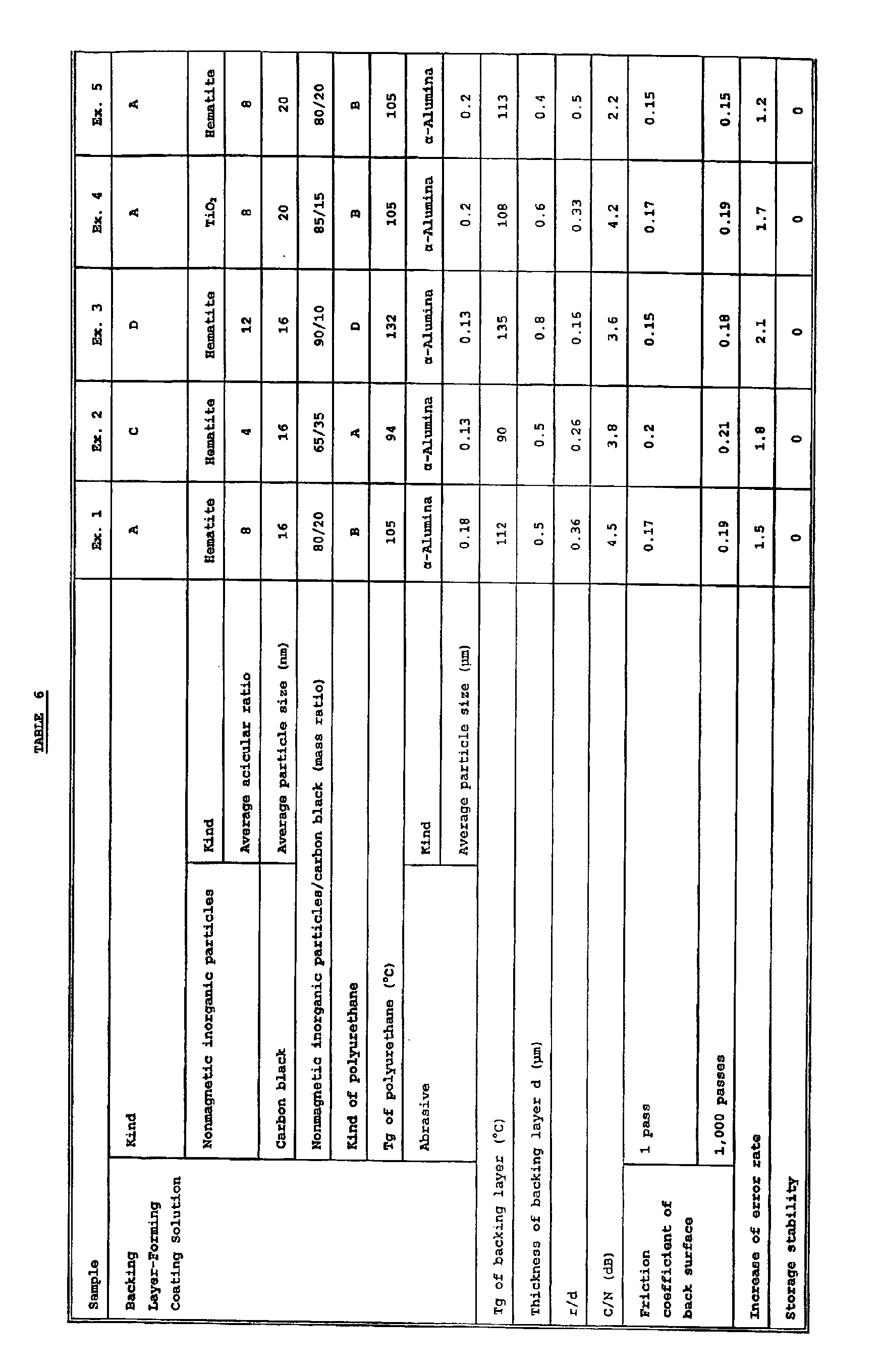
solution was coated in a dry thickness shown in Table 6 below
and dried. After drying, the magnetic layer was subjected
to calendering treatment with the calender of seven stages
of metal rolls by passing the web between the nips of metal
rolls six times (velocity: 100 m/min, linear pressure: 300 kg/cm,
temperature: 90°C) . The web was subjected to thermo-treatment
at 70°C for 48 hours, and slit in a width of 6.35 mm, thereby
a magnetic recording tape of Example 1 was obtained.
| Composition of Magnetic Layer-Forming Coating Solution |
| Ingredient | Mass Parts |
| a | Ferromagnetic metal powder (Note 1) | 100 |
| a | Polyurethane resin A (Note 2) | 18 |
| a | Phenylphosphonic acid | 5 |
| a | α-Al2O3 (average particle size: 0.15 µm) | 10 |
| a | Carbon black (average particle size: 80 nm) | 0.5 |
| a | Butyl stearate | 1 |
| a | Stearic acid | 1 |
| a | MEK | 120 |
| a | Cyclohexanone | 60 |
| b | Polyisocyanate (Collonate L) | 5 |
| c | MEK/cyclohexanone (1/1 mixed solvent) | 40 |
Note 1: Fe/Co: 100/30 (atomic ratio), Fe/Al: 100/11 (atomic ratio), coercive force (Hc): 192 kA/m (2,430 Oe), crystallite size: 110 angstroms, saturation magnetization moment (σs): 110 A·m2/kg, average long axis length : 0.045 µm, average acicular ratio (arithmetic mean of acicular ratios): 5.5
Note 2: Number average molecular weight: 36,000, Tg: 94°C, -SO3Na group: 6 µeq/g |
| Synthesis composition: |
| Hydrogenated bisphenol A | 0.6 mol |
| Polypropylene oxide adduct of bisphenol A | 0.3 mol |
| Na salt of bis(2-hydroxyethyl)-5-sulfoisophthalate | 0.05 mol |
| Diphenylmethane diisocyanate | 1.0 mol |
| Trimethylolpropane | 0.05 mol |
| Composition of Nonmagnetic Layer-Forming Coating Solution |
| Ingredient | Mass Parts |
| d | Acicular hematite (Note 3) | 80 |
| d | Polyurethane resin A (Note 2) | 20 |
| d | Phenylphosphonic acid | 5 |
| d | α-Al2O3 (average particle size: 0.15 µm) | 10 |
| d | Carbon black (average particle size: 80 nm) | 20 |
| d | Butyl stearate | 1 |
| d | Stearic acid | 1 |
| d | MEK | 120 |
| a | Cyclohexanone | 80 |
| e | Polyisocyanate (Collonate L) | 5 |
| f | MEK/cyclohexanone (1/1 mixed solvent) | 40 |
| Note 3: Average long axis length: 0.15 µm, average acicular ratio: 8, SBET : 52 m2/g, Surface-covering compound: Al2O3/SiO2 Note 4: DBP oil absorption amount: 120 ml/100 g, pH: 8, SBET: 52 m2/g |
| Composition of Backing Layer-Forming Coating Solution A |
| Ingredient | Mass Parts |
| g | Nonmagnetic inorganic particles (shown in Table 6) | Y |
| g | Polyurethane resin B (Note 5) | 20 |
| g | Phenylphosphonic acid | 5 |
| g | Abrasive (shown in Table 6) | 5 |
| g | Carbon black (shown in Table 6) | X |
| g | Carbon black (average particle size: 80 nm) | 5 |
| g | Stearic acid | 3 |
| g | MEK | 120 |
| g | Cyclohexanone | 120 |
| h | Polyisocyanate (Collonate L) | 5 |
| h | MEK/cyclohexanone (1/1 mixed solvent) | 80 |
Note: X + Y = 100
Note 5: Number average molecular weight: 45,000, Tg: 105°C, -SO3Na group: 6 µeq/g |
| Hydrogenated bisphenol A |
0.5 mol |
| Polypropylene oxide adduct of bisphenol A |
0.4 mol |
| Na salt of bis(2-hydroxyethyl)-5-sulfoisophthalate |
0.05 mol |
| Diphenylmethane diisocyanate |
1.0 mol |
| Trimethylolpropane |
0.05 mol |
EXAMPLES 2 TO 7 AND COMPARATIVE EXAMPLES 1 TO 3
Magnetic tapes having various backing layers were
prepared in the same manner as in Example 1 except for changing
each element shown in Table 6. In Table 6, in the case where
hematite is used as the nonmagnetic inorganic particles, the
ones in Examples 1, 5, 6 and 7 are the same as Note 3 in Table
2. In the carbon black in Table 6, the ones in Examples 1,
2 and 3 are the same as Note 4 in Table 2.
The following backing layer-forming coating solution
was also used.
| Composition of Backing Layer-Forming Coating Solution B |
| Ingredient | Mass Parts |
| i | Carbon black (average particle size: 15 nm) | 97 |
| i | Carbon black (average particle size: 250 nm) | 3 |
| i | Nitrocellulose resin | 110 |
| i | Polyurethane resin B (Note 6) | 30 |
| i | Calcium carbonate | 10 |
| i | Stearic acid | 1 |
| i | MEK | 60 |
| i | Cyclohexanone | 180 |
| j | Polyisocyanate (Collonate L) | 20 |
| k | MEK/cyclohexanone (1/1 mixed solvent) | 1,500 |
| Note 6: Number average molecular weight: 13,000, Tg: 33°C |
| Butanediol |
1.7 mol |
| Neopentyl glycol |
0.6 mol |
| Adipic acid |
1.3 mol |
| Diphenylmethane diisocyanate |
1.0 mol |
Ingredients i of the backing layer-forming coating
solution B shown in Table 4 were kneaded and then dispersed
with a sand mill. Ingredient j was added to the obtained
dispersion solution, further ingredient k was added, and the
solution was filtered through a filter having an average pore
diameter of 1 µm, thereby a backing layer-forming coating
solution in Comparative Example 1 was obtained.
Backing layer-forming coating solution C:
Polyurethane resin A was used in place of polyurethane
resin B in the composition of the backing layer-forming coating
solution A.
Backing layer-forming coating solution D:
Polyurethane resin D shown below was used in place of
polyurethane resin B in the composition of the backing
layer-forming coating solution A.
Synthesis composition of polyurethane resin D:
| Hydrogenated bisphenol A |
0.3 mol |
| Polypropylene oxide adduct of bisphenol A |
0.6 mol |
| Na salt of bis(2-hydroxyethyl)-5-sulfoisophthalate |
0.05 mol |
| Diphenylmethane diisocyanate |
1.0 mol |
| Trimethylolpropane |
0.05 mol |
Backing layer-forming coating solution E:
Polyurethane resin E shown below was used in place of
polyurethane resin B in the composition of the backing
layer-forming coating solution A.
Synthesis composition of polyurethane resin E:
| Butanediol |
0.6 mol |
| Polypropylene oxide adduct of bisphenol A |
0.3 mol |
| Na salt of bis(2-hydroxyethyl)-5-sulfoisophthalate |
0.05 mol |
| Diphenylmethane diisocyanate |
1.0 mol |
| Trimethylolpropane |
0.05 mol |
| Composition of Backing Layer-Forming Coating Solution F |
| Ingredient |
Mass Ratio |
| g |
Particulate TiO2 |
80 |
| g |
Polyurethane resin A (Note 2) |
6 |
| g |
Vinyl chloride resin (MR-110) |
12 |
| g |
Phenylphosphonic acid |
5 |
| g |
α-Al2O3 (average particle size: 0.18 µm) |
5 |
| g |
Carbon black (shown in Table 6) |
20 |
| g |
Carbon black (average particle size: 80 nm) |
5 |
| g |
Stearic acid |
3 |
| g |
MEK |
120 |
| g |
Cyclohexanone |
120 |
| h |
Polyisocyanate (Collonate L) |
5 |
| h |
MEK/cyclohexanone (1/1 mixed solvent) |
80 |
The following tests and measurement were performed with
each of the prepared magnetic recording tapes.
Tests and measuring methods:
(1) Measurement of C/N ratio
Measurement was performed by attaching to a drum tester
a recording head (MIG, gap length: 0.15 µm, a track breadth:
18 µm, 1.8 T) and an MR head for reproduction (a shield type
head, gap length between shields: 0.2 µm, a track breadth:
4 µm)
Single frequency signals were recorded at relative speed
of head-medium of 10 m/min and recording wavelength of 0.2 µm
(50 MHz) , and the reproduced signals were analyzed by frequency
with a spectrum analyzer (a product manufactured by Shibasoku
K.K.), and the ratio of the output voltage of the above single
frequency signals to the noise voltage 1 MHz apart was taken
as a C/N ratio (dB). Bias current was applied to the MR head
at reproducing time so that the reproduction output became
maximum.
(2) Measurement of friction coefficient of back surface
Each magnetic recording tape was laid over SUS 420J
(4 mmϕ) at an angle of 180°. The tape was slid with 20 g of
a load at a speed of 14 mm/sec, and the friction coefficient
was obtained by the following Euler's equation:
µ = (1/π)ln(T2/10)
wherein T2 is a sliding resistance value (g).
(3) Evaluation of running durability
The increase of error rates before and after 1, 000 passes
of repeated running of a tape (after running/before running)
was measured by DVC-PRO VTR (a product of Matsushita Electric
Industrial Co., Ltd.).
(4) Storage stability
A 370 meter length of a tape was wound on a reel for
DVC-PRO and preserved under the atmosphere of 60°C 90% RH for
a month. The tape was rewound after a month, and the number
of adhesion on the overall length was counted.
(5) Tg of backing layer
A backing layer-forming coating solution was coated
on a base film in a thickness of 1 µm and dried to thereby
prepare a sample. The dynamic visco-elasticity (vibration
frequency: 110 Hz) of the sample was measured by Rheovibron
(a product of Orientec Co. (former Toyo Baldwin)). The dynamic
visco-elasticity of the base film alone was also measured,
and E" peak obtained by subtracting the latter value from the
former value was taken as Tg.
The results obtained are shown in the following Table
6.
From the results in Table 6, it can be seen that the
samples according to the present invention are high in C/N
ratio, low in error rate increase, and storage stability is
good. Comparative samples are low in C/N ratio as compared
with the samples in the invention , and high in error rate increase.
The present invention can provide a magnetic recording
medium excellent in a C/N ratio and running durability by using
nonmagnetic inorganic particles having a specific figure and
carbon black having a specific size respectively in specific
amounts in a backing layer, and adjusting Tg of the backing
layer to a specific range, thereby the surface smoothness of
the backing layer can be ensured, the setoff of the backing
layer to the magnetic layer and the adhesion during storage
can be prevented.
This application is based on Japanese Patent application
JP 2002-157510, filed May 30, 2002, the entire content of which
is hereby incorporated by reference, the same as if set forth
at length.