EP1367331B1 - Compact air-cooling device for a closed technical cabinet - Google Patents
Compact air-cooling device for a closed technical cabinet Download PDFInfo
- Publication number
- EP1367331B1 EP1367331B1 EP03101460A EP03101460A EP1367331B1 EP 1367331 B1 EP1367331 B1 EP 1367331B1 EP 03101460 A EP03101460 A EP 03101460A EP 03101460 A EP03101460 A EP 03101460A EP 1367331 B1 EP1367331 B1 EP 1367331B1
- Authority
- EP
- European Patent Office
- Prior art keywords
- air
- housing
- closed technical
- technical cabinet
- cabinet
- Prior art date
- Legal status (The legal status is an assumption and is not a legal conclusion. Google has not performed a legal analysis and makes no representation as to the accuracy of the status listed.)
- Expired - Fee Related
Links
Images


Classifications
-
- H—ELECTRICITY
- H05—ELECTRIC TECHNIQUES NOT OTHERWISE PROVIDED FOR
- H05K—PRINTED CIRCUITS; CASINGS OR CONSTRUCTIONAL DETAILS OF ELECTRIC APPARATUS; MANUFACTURE OF ASSEMBLAGES OF ELECTRICAL COMPONENTS
- H05K7/00—Constructional details common to different types of electric apparatus
- H05K7/20—Modifications to facilitate cooling, ventilating, or heating
- H05K7/20536—Modifications to facilitate cooling, ventilating, or heating for racks or cabinets of standardised dimensions, e.g. electronic racks for aircraft or telecommunication equipment
- H05K7/20618—Air circulating in different modes under control of air guidance flaps
-
- F—MECHANICAL ENGINEERING; LIGHTING; HEATING; WEAPONS; BLASTING
- F24—HEATING; RANGES; VENTILATING
- F24F—AIR-CONDITIONING; AIR-HUMIDIFICATION; VENTILATION; USE OF AIR CURRENTS FOR SCREENING
- F24F1/00—Room units for air-conditioning, e.g. separate or self-contained units or units receiving primary air from a central station
- F24F1/02—Self-contained room units for air-conditioning, i.e. with all apparatus for treatment installed in a common casing
- F24F1/022—Self-contained room units for air-conditioning, i.e. with all apparatus for treatment installed in a common casing comprising a compressor cycle
- F24F1/027—Self-contained room units for air-conditioning, i.e. with all apparatus for treatment installed in a common casing comprising a compressor cycle mounted in wall openings, e.g. in windows
-
- F—MECHANICAL ENGINEERING; LIGHTING; HEATING; WEAPONS; BLASTING
- F24—HEATING; RANGES; VENTILATING
- F24F—AIR-CONDITIONING; AIR-HUMIDIFICATION; VENTILATION; USE OF AIR CURRENTS FOR SCREENING
- F24F13/00—Details common to, or for air-conditioning, air-humidification, ventilation or use of air currents for screening
- F24F13/08—Air-flow control members, e.g. louvres, grilles, flaps or guide plates
- F24F13/10—Air-flow control members, e.g. louvres, grilles, flaps or guide plates movable, e.g. dampers
- F24F13/14—Air-flow control members, e.g. louvres, grilles, flaps or guide plates movable, e.g. dampers built up of tilting members, e.g. louvre
-
- F—MECHANICAL ENGINEERING; LIGHTING; HEATING; WEAPONS; BLASTING
- F24—HEATING; RANGES; VENTILATING
- F24F—AIR-CONDITIONING; AIR-HUMIDIFICATION; VENTILATION; USE OF AIR CURRENTS FOR SCREENING
- F24F11/00—Control or safety arrangements
- F24F11/0001—Control or safety arrangements for ventilation
- F24F2011/0006—Control or safety arrangements for ventilation using low temperature external supply air to assist cooling
-
- Y—GENERAL TAGGING OF NEW TECHNOLOGICAL DEVELOPMENTS; GENERAL TAGGING OF CROSS-SECTIONAL TECHNOLOGIES SPANNING OVER SEVERAL SECTIONS OF THE IPC; TECHNICAL SUBJECTS COVERED BY FORMER USPC CROSS-REFERENCE ART COLLECTIONS [XRACs] AND DIGESTS
- Y02—TECHNOLOGIES OR APPLICATIONS FOR MITIGATION OR ADAPTATION AGAINST CLIMATE CHANGE
- Y02B—CLIMATE CHANGE MITIGATION TECHNOLOGIES RELATED TO BUILDINGS, e.g. HOUSING, HOUSE APPLIANCES OR RELATED END-USER APPLICATIONS
- Y02B30/00—Energy efficient heating, ventilation or air conditioning [HVAC]
- Y02B30/54—Free-cooling systems
Definitions
- the present invention relates to a compact air-cooling device for a closed technical cabinet containing heat generating equipment, as e.g. electrical switch and control gear and telecommunication equipment.
- heat generating equipment as e.g. electrical switch and control gear and telecommunication equipment.
- Simple forced air-cooling systems for closed technical cabinets use a fan to extract hot air from the closed technical cabinet.
- the hot air within the cabinet is simply replaced with air from the outside environment of the cabinet, which enters into the cabinet through ventilation openings.
- a major disadvantage of these simple ventilation systems is that in summer the outside environment of the cabinet may be too hot to warrant that a maximum temperature limit is not exceeded within the cabinet.
- Their advantages are of course the simplicity of the equipment (only a fan and a thermostat are required) and low electric power consumption.
- the forced air-cooling systems may be easily powered by an emergency power supply in case of power failure of the main electric supply.
- Such a compact mechanical air-cooling unit includes a mechanical refrigeration unit with a compressor, an evaporator arranged in a primary air circuit and a condenser arranged in a secondary air circuit.
- a primary fan circulates the cabinet air in a closed loop through the primary air circuit, wherein the cabinet air is cooled in the evaporator.
- a secondary fan circulates air from the outside environment of the cabinet through a separate secondary air circuit, wherein it cools the condenser.
- a major disadvantage of such a mechanical refrigeration system is a rather high electric power consumption over the year. Furthermore, due to the high power draw of the refrigeration compressor, which has usually one single stage, the mechanical air-cooling unit is usually not connected to an emergency power supply and there is consequently no cooling of the cabinet in the event of a power failure.
- the technical problem underlying the present invention is to provide an air-cooling device for a closed technical cabinet containing heat generating equipment, wherein said compact air-cooling device shall be compact enough to be easily integrated in the body of the cabinet, shall be able to warrant a close temperature control within the cabinet during the whole year, shall allow an optimization of energy consumption and shall have a reduced power draw in case of emergency power supply.
- This problem is solved by a compact air-cooling device as claimed in claim 1.
- Preferred embodiments of the claimed solution are defined in the dependant claims.
- a compact air-cooling device in accordance with the present invention comprises a housing, a mechanical refrigeration unit including an evaporator and an condenser mounted in the housing, as well as primary fan means and secondary fan means mounted in the housing for circulating air through the evaporator and the condenser.
- Partition elements are mounted in the housing for defining therein a primary air circuit and a separate secondary air circuit.
- the primary air circuit is designed so that the primary fan means takes in air through an inside air intake chamber, which is in direct communication with the inside of the closed technical cabinet, sucks it through the evaporator and blows it back into the inside of the closed technical cabinet, so as to provide a mechanical cooling in a closed loop with air from the inside of the closed technical cabinet.
- the secondary air circuit is designed so that the secondary fan means takes in air from the outside environment of the closed technical cabinet and blows it through the condenser back into the outside environment of the closed technical cabinet, so as to cool the condenser with air from the outside environment of the closed technical cabinet.
- the aforementioned partition elements include movable elements which can be brought into an auxiliary position in which the secondary air circuit is in communication with the primary air circuit upstream of the evaporator, and the inside air intake chamber is sealed off from the primary air circuit and is in direct communication with the outside environment of the closed technical cabinet.
- the first mode of operation consists in a mechanical cooling with air from the inside of the closed technical cabinet circulated in closed loop through the primary air circuit.
- the device operates just in the same way as the afore-described compact mechanical air-cooling units for technical cabinets.
- the second mode of operation consists in a mechanical cooling in an open loop with air from the outside environment of the closed technical cabinet, wherein air from the inside of the closed technical cabinet is evacuated by overpressure through the inside air intake chamber directly into the outside environment of the closed technical cabinet.
- This mode of operation allows to save refrigeration energy and to warrant nevertheless a close temperature control if the "outside air” is colder than the "inside air” but not cold enough to warrant free cooling of the cabinet.
- the third mode of operation consists in a free cooling of the closed technical cabinet with air from the outside environment of the closed technical cabinet that is not subjected to a mechanical refrigeration.
- a compact device in accordance with the present invention warrants, during the whole year, a close control of the temperature inside the closed technical cabinet, while simultaneously allowing an optimization of energy consumption by switching between its three modes of operation in function of the thermodynamic air conditions in the outside and inside environments of the closed technical cabinet.
- a device in accordance with the present invention has to be powered by an electric emergency supply
- the device can be set to operate in the free cooling mode, wherein the electric energy supply for the cooling unit and the secondary fan means is interrupted, so that the device has a considerably reduced power draw in case of emergency power supply.
- the overall dimensions of the housing of a device in accordance with the present invention which allows three modes of operation, can be substantially of the same size as those of a compact mechanical air-cooling unit that allows only mechanical cooling in a closed loop with air from the inside of the closed technical cabinet.
- the compact housing has a front side, a rear side, an upper side, a lower side and two lateral sides and is designed to be mounted on or in an enclosure element of the closed technical cabinet, so that its front side is in direct communication with the outside environment of the closed technical cabinet.
- This preferred embodiment can be particularly compact if the condenser is mounted in an opening in the front side of the housing, so that its upper edge is located close to the upper side of the housing, if the evaporator is mounted obliquely in the housing, wherein its lower edge is located substantially in the middle of the housing and its upper edge is located in a corner of the housing where the rear side joins the upper side of the housing, and if the partition elements include a fixed partition wall extending from the lower edge of the evaporator to the upper edge of the condenser, so as to separate a condenser inlet chamber from an evaporator outlet chamber.
- the partition elements define an outside air i n-take chamber in which the secondary fan means is located and which is in direct communication with the condenser inlet chamber.
- the movable partition elements advantageously include a damper that is movable between a first position, in which it seals off the outside air intake chamber from the primary air circuit, and a second position, in which it establishes a direct communication between the outside air intake chamber and the primary air circuit upstream of the evaporator and simultaneously seals off the inside air intake chamber from the primary air circuit.
- the movable partition elements further include a damper capable of opening and closing a communication between the inside air intake chamber and an inside air outlet opening in the housing that opens into the outside environment of the closed technical cabinet.
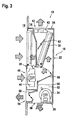
- FIG. 1 to 3 show a schematic section through an air-cooling device 10 for a closed technical cabinet containing heat generating equipment, such as e.g. electrical switch and control gear and active telecommunication equipment.
- This closed technical cabinet is schematically represented by an element 12 of its enclosure, wherein the inside of the cabinet is globally identified with reference number 14 and its outside environment is globally identified with reference number 16.
- the air-cooling device 10 comprises a prismatic housing 18 that is mounted in an opening of the enclosure element 12. It has a front side 20, a rear side 22, an upper side 24, a lower side 26 and two lateral sides. The front side 20 is in direct communication with the outside environment 16 of the closed technical cabinet. All the other sides of the housing 18 are located within the inside 14 of the closed technical cabinet. It remains to be pointed out that the enclosure element 12 is advantageously a hinged door element of the closed technical cabinet, so that the air-cooling device 10 is easily accessible for maintenance by simply opening the hinged door element 12. Furthermore, it will be noted that the overall dimensions of the prismatic housing 18 must be rather small, so that as to take a minimum of space within the cabinet. Typical overall dimensions for the housing 18 are e.g.: a height of about 750 mm, a depth of about 250 mm and a width (that is the dimension perpendicular to the plane of the figures) of about 300 mm.
- a mechanical refrigeration unit comprising an evaporator 30, a condenser 32 and a compressor 34.
- the condenser 32 is mounted in an opening in the front side 20 of the housing so that it is in direct communication with the outside environment 16 of the closed technical cabinet. Its upper edge is located close to the upper side 24 of the housing 18. Its lower edge is located at about half the height of the front side 20.
- the evaporator 30 is mounted obliquely within the housing 18, wherein its lower edge is located substantially in the middle of the housing 18 and its upper edge is located in a corner of the housing where the rear side 22 joins said upper side 24 of the housing 18.
- a fixed partition wall 36 extends from the lower edge of the evaporator 30 to the upper edge of the condenser 32, so as to separate within the housing 18 a condenser inlet chamber 38 from an evaporator outlet chamber 40. It will be appreciated that-due to the aforementioned design-both the evaporator 30 and the condenser 32 may have a rather big heat exchange surface with a rather small pressure drop, which results of course in a high energy efficiency.
- the air-cooling device 10 further comprises primary fan means and secondary fan means mounted in the housing 18 for circulating air through the evaporator 20 and the condenser 22.
- the primary fan means advantageously comprises one or more axial fans 42 mounted in a supply air outlet opening 43 of the upper side 24 of the housing 18.
- the secondary fan means advantageously comprises a radial fan 44 mounted in an outside air intake chamber 46 of the housing 18, so as to be able take in air from the outside environment 16 through an outside air inlet opening 48, which is arranged in the front side 20 of the housing 18 just below the condenser 32.
- An inside air inlet opening 50 is provided in the lower side 26 of the housing 18 (or alternatively in the lower part of the rear side 22 or the lateral sides). This inside air inlet opening 50 opens into an inside air intake chamber 52 of the housing 18, in which the compressor 34 is advantageously arranged.
- An inside air outlet opening 54 is provided in the front side 20 of the housing 18, near the lower edge of the latter.
- air-cooling device 10 further includes an air filter 39 that is arranged upstream of the evaporator 30, where it extends obliquely upwards from the lower edge of the partition wall 36 to the rear side 22 over substantially the whole width of the housing 18. It will be appreciated that this air filter 39 may be easily exchanged from the rear side 22 of the housing 18. Furthermore, because of its rather big filter surface, it achieves a rather good filtering efficiency with a small pressure drop.
- the aforementioned fixed partition wall 36 and further fixed and movable partition elements 56, 58, 60 cooperate to delimit within the housing 18 a primary air circuit and a secondary air circuit.
- the primary fan means 42 takes in air from the inside 14 through the air inlet opening 50 of the inside air intake chamber 50, sucks it through the evaporator 30 into the evaporator outlet chamber 40 and blows it back into the inside 14 of the closed technical cabinet.
- the secondary fan means 44 takes in air from the outside environment 16 into the outside air intake chamber 46.
- the movable partition element identified by reference number 58 is conceived as a first damper that is movable between a first position, in which it seals off the outside air intake chamber 46 from the primary air circuit (see Fig. 1), and a second position, in which it establishes a direct communication between the outside air intake chamber 46 and the primary air circuit upstream of the evaporator 30 and simultaneously seals off the inside air intake chamber 52 from the primary air circuit (see Fig. 2).
- the movable partition element identified by reference number 60 is conceived as a second damper that is movable between a first position, in which it seals off the inside air intake chamber 52 from the inside air outlet opening 54 (see Fig. 1), and a second position, in which it establishes a direct communication between the inside air intake chamber 52 and the inside air outlet opening 54 (see Fig. 2).
- the outside air taken in by the secondary fan means 44 divides itself into two streams.
- a first stream passes through the condenser 32 (wherein it condenses the refrigerant) back into the outside environment 16.
- a second stream passes through the evaporator 30 (wherein it is cooled by evaporation of the refrigerant) into the evaporator outlet chamber 40 and is blown by the primary fan means 42 into the closed technical cabinet.
- Surplus air leaves the closed technical cabinet by overpressure, passing through the inside air intake chamber 52, the open damper 60 and the inside air outlet opening 54 into the outside environment 16.
- Mechanical cooling with outside air is of advantage if the thermodynamic conditions of the outside air are, with regard to energy consumption of the mechanical cooling unit, more favorable than the thermodynamic conditions of the re-circulated inside air.
- the dampers 58 and 60 are in the same position as in Fig. 2.
- the secondary fan means 44 is shut off, as well as the compressor 34.
- the primary fan means 42 now sucks outside air through the outside air inlet opening 48 and the condenser 32 and blows it, without any further mechanical refrigeration of the outside air, into the closed cabinet.
- This mode of operation is applied if the thermodynamic conditions of the outside air allow a free cooling of the closed technical cabinet. Due to the particular design of airflow path in the air-cooling device 10, only a small overpressure will establish in the cabinet during free cooling. This allows to warrant a high airflow and energy efficiency for the free cooling operation mode.
- the compact air-cooling device 10 of the present invention may further include an electrical heating element 60.
- the latter is advantageously arranged in the evaporator outlet chamber 40 and is capable of reheating the supply air, e.g. in case of free cooling with very cold outside air.
- control means measures the thermodynamic conditions (temperature, humidity) of the air outside and inside the closed technical cabinet and sets the dampers 58, 60 either in the position of Fig. 1 or Fig. 2 depending on these thermodynamic conditions. Furthermore, if the thermodynamic conditions of the outside air allow a free cooling of the closed technical cabinet, the control means shuts off the secondary fan means 44, as well as the compressor 34, with the dampers 58, 60 set in the position illustrated in Fig. 2.
- the compact air-cooling device 10 of the present invention is advantageously connected to a main electric supply and to an electric emergency supply.
- control means automatically set the dampers 58, 60 in the position illustrated in Fig. 2, and the electric energy supply for the compressor 34 of the cooling unit and the secondary fan means 44 is interrupted.
- the primary fan means 42 and the control means of the dampers 58, 60 are e.g. powered via a 48 V DC power supply with battery back-up, and the secondary fan means 44 and the compressor 34 are directly connected to AC mains.
- the housing 18 can be mounted entirely on the inside of the enclosure element 12 of the closed technical cabinet, as shown in Fig. 1 to 3, or alternatively, mounted "half in, half out", i.e. with the front side 20 protruding from the front face of the enclosure element 12, but the inside air inlet opening 50 and the supply air outlet opening 43 still lying within the closed technical cabinet, which requires less place within the cabinet.
- the housing 18 is made slightly higher, and the inside air inlet opening 50 and the supply air outlet opening 43 are both integrated in the rear side 22 of the housing 18. This embodiment can then be mounted entirely on the outside of the enclosure element 12 of the closed technical cabinet.
- the overall dimensions of the housing 18, can be substantially of the same size as those of a housing of a compact mechanical air-cooling unit exclusively allowing mechanical cooling in a closed loop with air from the inside of the closed technical cabinet.
Abstract
Description
- The present invention relates to a compact air-cooling device for a closed technical cabinet containing heat generating equipment, as e.g. electrical switch and control gear and telecommunication equipment.
- More and more of such closed technical cabinets need forced air-cooling during the whole year, to warrant that the temperature within the cabinet does not exceed the maximum temperature imposed by the equipment manufacturers.
- Simple forced air-cooling systems for closed technical cabinets use a fan to extract hot air from the closed technical cabinet. The hot air within the cabinet is simply replaced with air from the outside environment of the cabinet, which enters into the cabinet through ventilation openings. A major disadvantage of these simple ventilation systems is that in summer the outside environment of the cabinet may be too hot to warrant that a maximum temperature limit is not exceeded within the cabinet. Their advantages are of course the simplicity of the equipment (only a fan and a thermostat are required) and low electric power consumption. Furthermore, due to a low electric power draw, the forced air-cooling systems may be easily powered by an emergency power supply in case of power failure of the main electric supply.
- If a closer temperature control within the cabinet is required, it is known to fit a compact mechanical air-cooling unit within a wall element of the cabinet to be cooled (see for example GB-A-2251064). Such a compact mechanical air-cooling unit includes a mechanical refrigeration unit with a compressor, an evaporator arranged in a primary air circuit and a condenser arranged in a secondary air circuit. A primary fan circulates the cabinet air in a closed loop through the primary air circuit, wherein the cabinet air is cooled in the evaporator. A secondary fan circulates air from the outside environment of the cabinet through a separate secondary air circuit, wherein it cools the condenser. A major disadvantage of such a mechanical refrigeration system is a rather high electric power consumption over the year. Furthermore, due to the high power draw of the refrigeration compressor, which has usually one single stage, the mechanical air-cooling unit is usually not connected to an emergency power supply and there is consequently no cooling of the cabinet in the event of a power failure.
- The technical problem underlying the present invention is to provide an air-cooling device for a closed technical cabinet containing heat generating equipment, wherein said compact air-cooling device shall be compact enough to be easily integrated in the body of the cabinet, shall be able to warrant a close temperature control within the cabinet during the whole year, shall allow an optimization of energy consumption and shall have a reduced power draw in case of emergency power supply. This problem is solved by a compact air-cooling device as claimed in claim 1. Preferred embodiments of the claimed solution are defined in the dependant claims.
- A compact air-cooling device in accordance with the present invention comprises a housing, a mechanical refrigeration unit including an evaporator and an condenser mounted in the housing, as well as primary fan means and secondary fan means mounted in the housing for circulating air through the evaporator and the condenser. Partition elements are mounted in the housing for defining therein a primary air circuit and a separate secondary air circuit. The primary air circuit is designed so that the primary fan means takes in air through an inside air intake chamber, which is in direct communication with the inside of the closed technical cabinet, sucks it through the evaporator and blows it back into the inside of the closed technical cabinet, so as to provide a mechanical cooling in a closed loop with air from the inside of the closed technical cabinet. The secondary air circuit is designed so that the secondary fan means takes in air from the outside environment of the closed technical cabinet and blows it through the condenser back into the outside environment of the closed technical cabinet, so as to cool the condenser with air from the outside environment of the closed technical cabinet. In accordance with an important aspect of the present invention, the aforementioned partition elements include movable elements which can be brought into an auxiliary position in which the secondary air circuit is in communication with the primary air circuit upstream of the evaporator, and the inside air intake chamber is sealed off from the primary air circuit and is in direct communication with the outside environment of the closed technical cabinet.
- It will be appreciated that with a compact air cooling device in accordance with the present invention three modes of operation are possible for cooling the cabinet. The first mode of operation consists in a mechanical cooling with air from the inside of the closed technical cabinet circulated in closed loop through the primary air circuit. In this first mode, the device operates just in the same way as the afore-described compact mechanical air-cooling units for technical cabinets. The second mode of operation consists in a mechanical cooling in an open loop with air from the outside environment of the closed technical cabinet, wherein air from the inside of the closed technical cabinet is evacuated by overpressure through the inside air intake chamber directly into the outside environment of the closed technical cabinet. This mode of operation allows to save refrigeration energy and to warrant nevertheless a close temperature control if the "outside air" is colder than the "inside air" but not cold enough to warrant free cooling of the cabinet. The third mode of operation consists in a free cooling of the closed technical cabinet with air from the outside environment of the closed technical cabinet that is not subjected to a mechanical refrigeration. In conclusion, a compact device in accordance with the present invention warrants, during the whole year, a close control of the temperature inside the closed technical cabinet, while simultaneously allowing an optimization of energy consumption by switching between its three modes of operation in function of the thermodynamic air conditions in the outside and inside environments of the closed technical cabinet. Furthermore, if a device in accordance with the present invention has to be powered by an electric emergency supply, the device can be set to operate in the free cooling mode, wherein the electric energy supply for the cooling unit and the secondary fan means is interrupted, so that the device has a considerably reduced power draw in case of emergency power supply. Last but not least, it will be appreciated that the overall dimensions of the housing of a device in accordance with the present invention, which allows three modes of operation, can be substantially of the same size as those of a compact mechanical air-cooling unit that allows only mechanical cooling in a closed loop with air from the inside of the closed technical cabinet.
- In a preferred embodiment, the compact housing has a front side, a rear side, an upper side, a lower side and two lateral sides and is designed to be mounted on or in an enclosure element of the closed technical cabinet, so that its front side is in direct communication with the outside environment of the closed technical cabinet. This preferred embodiment can be particularly compact if the condenser is mounted in an opening in the front side of the housing, so that its upper edge is located close to the upper side of the housing, if the evaporator is mounted obliquely in the housing, wherein its lower edge is located substantially in the middle of the housing and its upper edge is located in a corner of the housing where the rear side joins the upper side of the housing, and if the partition elements include a fixed partition wall extending from the lower edge of the evaporator to the upper edge of the condenser, so as to separate a condenser inlet chamber from an evaporator outlet chamber.
- In a preferred embodiment, the partition elements define an outside air i n-take chamber in which the secondary fan means is located and which is in direct communication with the condenser inlet chamber. The movable partition elements advantageously include a damper that is movable between a first position, in which it seals off the outside air intake chamber from the primary air circuit, and a second position, in which it establishes a direct communication between the outside air intake chamber and the primary air circuit upstream of the evaporator and simultaneously seals off the inside air intake chamber from the primary air circuit. In a preferred embodiment, the movable partition elements further include a damper capable of opening and closing a communication between the inside air intake chamber and an inside air outlet opening in the housing that opens into the outside environment of the closed technical cabinet.
- The present invention will now be described, by way of example, with reference to the accompanying drawings, in which:
- Fig. 1:
- is a schematic section through an air-cooling device in accordance with the invention, illustrating mechanical cooling in a closed loop with re-circulated air from the inside of the cabinet;
- Fig. 2:
- is a schematic section through the air-cooling device of Fig. 1, illustrating mechanical cooling with air from the outside environment of the cabinet; and
- Fig. 3:
- is a schematic section through the air-cooling device of Fig. 1, illustrating free cooling with air from the outside environment of the cabinet.
- Fig. 1 to 3 show a schematic section through an air-
cooling device 10 for a closed technical cabinet containing heat generating equipment, such as e.g. electrical switch and control gear and active telecommunication equipment. This closed technical cabinet is schematically represented by anelement 12 of its enclosure, wherein the inside of the cabinet is globally identified withreference number 14 and its outside environment is globally identified withreference number 16. - The air-
cooling device 10 comprises aprismatic housing 18 that is mounted in an opening of theenclosure element 12. It has afront side 20, arear side 22, anupper side 24, alower side 26 and two lateral sides. Thefront side 20 is in direct communication with theoutside environment 16 of the closed technical cabinet. All the other sides of thehousing 18 are located within theinside 14 of the closed technical cabinet. It remains to be pointed out that theenclosure element 12 is advantageously a hinged door element of the closed technical cabinet, so that the air-cooling device 10 is easily accessible for maintenance by simply opening the hingeddoor element 12. Furthermore, it will be noted that the overall dimensions of theprismatic housing 18 must be rather small, so that as to take a minimum of space within the cabinet. Typical overall dimensions for thehousing 18 are e.g.: a height of about 750 mm, a depth of about 250 mm and a width (that is the dimension perpendicular to the plane of the figures) of about 300 mm. - In the
housing 18 is mounted a mechanical refrigeration unit comprising anevaporator 30, acondenser 32 and acompressor 34. Thecondenser 32 is mounted in an opening in thefront side 20 of the housing so that it is in direct communication with theoutside environment 16 of the closed technical cabinet. Its upper edge is located close to theupper side 24 of thehousing 18. Its lower edge is located at about half the height of thefront side 20. Theevaporator 30 is mounted obliquely within thehousing 18, wherein its lower edge is located substantially in the middle of thehousing 18 and its upper edge is located in a corner of the housing where therear side 22 joins saidupper side 24 of thehousing 18. Afixed partition wall 36 extends from the lower edge of theevaporator 30 to the upper edge of thecondenser 32, so as to separate within the housing 18 acondenser inlet chamber 38 from anevaporator outlet chamber 40. It will be appreciated that-due to the aforementioned design-both theevaporator 30 and thecondenser 32 may have a rather big heat exchange surface with a rather small pressure drop, which results of course in a high energy efficiency. - The air-
cooling device 10 further comprises primary fan means and secondary fan means mounted in thehousing 18 for circulating air through theevaporator 20 and thecondenser 22. The primary fan means advantageously comprises one or moreaxial fans 42 mounted in a supply air outlet opening 43 of theupper side 24 of thehousing 18. The secondary fan means advantageously comprises aradial fan 44 mounted in an outsideair intake chamber 46 of thehousing 18, so as to be able take in air from theoutside environment 16 through an outsideair inlet opening 48, which is arranged in thefront side 20 of thehousing 18 just below thecondenser 32. An insideair inlet opening 50 is provided in thelower side 26 of the housing 18 (or alternatively in the lower part of therear side 22 or the lateral sides). This insideair inlet opening 50 opens into an insideair intake chamber 52 of thehousing 18, in which thecompressor 34 is advantageously arranged. An insideair outlet opening 54 is provided in thefront side 20 of thehousing 18, near the lower edge of the latter. - It will also be noted that air-cooling
device 10 further includes anair filter 39 that is arranged upstream of theevaporator 30, where it extends obliquely upwards from the lower edge of thepartition wall 36 to therear side 22 over substantially the whole width of thehousing 18. It will be appreciated that thisair filter 39 may be easily exchanged from therear side 22 of thehousing 18. Furthermore, because of its rather big filter surface, it achieves a rather good filtering efficiency with a small pressure drop. - In the mode of operation illustrated in Fig. 1 (i.e, mechanical cooling in a closed loop), the aforementioned fixed
partition wall 36 and further fixed andmovable partition elements air intake chamber 50, sucks it through theevaporator 30 into theevaporator outlet chamber 40 and blows it back into the inside 14 of the closed technical cabinet. In the secondary air circuit, the secondary fan means 44 takes in air from theoutside environment 16 into the outsideair intake chamber 46. From the latter the air flows into thecondenser inlet chamber 38, to leave thehousing 18 through thecondenser 32 into theoutside environment 16. It will be noted that in this mode of operation there is no significant air exchange between the primary air circuit and the secondary air circuit. The cabinet air is re-circulated through the primary air circuit and cooled therein by the refrigerant evaporating in theevaporator 30, whereas the outside air is circulated through the secondary air circuit to condense the refrigerant in thecondenser 32. - Referring now simultaneously at Fig. 1 and 2, it will be noted that the movable partition element identified by
reference number 58 is conceived as a first damper that is movable between a first position, in which it seals off the outsideair intake chamber 46 from the primary air circuit (see Fig. 1), and a second position, in which it establishes a direct communication between the outsideair intake chamber 46 and the primary air circuit upstream of theevaporator 30 and simultaneously seals off the insideair intake chamber 52 from the primary air circuit (see Fig. 2). The movable partition element identified byreference number 60 is conceived as a second damper that is movable between a first position, in which it seals off the insideair intake chamber 52 from the inside air outlet opening 54 (see Fig. 1), and a second position, in which it establishes a direct communication between the insideair intake chamber 52 and the inside air outlet opening 54 (see Fig. 2). - In the mode of operation illustrated in Fig. 2, the outside air taken in by the secondary fan means 44 divides itself into two streams. A first stream passes through the condenser 32 (wherein it condenses the refrigerant) back into the
outside environment 16. A second stream passes through the evaporator 30 (wherein it is cooled by evaporation of the refrigerant) into theevaporator outlet chamber 40 and is blown by the primary fan means 42 into the closed technical cabinet. Surplus air leaves the closed technical cabinet by overpressure, passing through the insideair intake chamber 52, theopen damper 60 and the inside air outlet opening 54 into theoutside environment 16. Mechanical cooling with outside air, as illustrated in Fig. 2, is of advantage if the thermodynamic conditions of the outside air are, with regard to energy consumption of the mechanical cooling unit, more favorable than the thermodynamic conditions of the re-circulated inside air. - In the mode of operation illustrated in Fig. 3, the
dampers compressor 34. The primary fan means 42 now sucks outside air through the outsideair inlet opening 48 and thecondenser 32 and blows it, without any further mechanical refrigeration of the outside air, into the closed cabinet. This mode of operation is applied if the thermodynamic conditions of the outside air allow a free cooling of the closed technical cabinet. Due to the particular design of airflow path in the air-coolingdevice 10, only a small overpressure will establish in the cabinet during free cooling. This allows to warrant a high airflow and energy efficiency for the free cooling operation mode. - The compact air-cooling
device 10 of the present invention may further include anelectrical heating element 60. The latter is advantageously arranged in theevaporator outlet chamber 40 and is capable of reheating the supply air, e.g. in case of free cooling with very cold outside air. - The switching between the three modes of operation is advantageously govemed by control means (not shown). This control means measures the thermodynamic conditions (temperature, humidity) of the air outside and inside the closed technical cabinet and sets the
dampers compressor 34, with thedampers - The compact air-cooling
device 10 of the present invention is advantageously connected to a main electric supply and to an electric emergency supply. When, in case of a power failure of the main electric supply, the device has to be powered by the electric emergency supply, control means automatically set thedampers compressor 34 of the cooling unit and the secondary fan means 44 is interrupted. In a preferred embodiment the primary fan means 42 and the control means of thedampers compressor 34 are directly connected to AC mains. - It remains to be pointed out that the
housing 18 can be mounted entirely on the inside of theenclosure element 12 of the closed technical cabinet, as shown in Fig. 1 to 3, or alternatively, mounted "half in, half out", i.e. with thefront side 20 protruding from the front face of theenclosure element 12, but the insideair inlet opening 50 and the supplyair outlet opening 43 still lying within the closed technical cabinet, which requires less place within the cabinet. Furthermore, in a less preferred embodiment, thehousing 18 is made slightly higher, and the insideair inlet opening 50 and the supplyair outlet opening 43 are both integrated in therear side 22 of thehousing 18. This embodiment can then be mounted entirely on the outside of theenclosure element 12 of the closed technical cabinet. - Finally, it will be appreciated that the overall dimensions of the
housing 18, can be substantially of the same size as those of a housing of a compact mechanical air-cooling unit exclusively allowing mechanical cooling in a closed loop with air from the inside of the closed technical cabinet.
Claims (21)
- A compact air-cooling device for a closed technical cabinet containing heat generating equipment necessitating closely controlled temperature conditions, said air-cooling device comprising:a housing (18);a mechanical refrigeration unit including an evaporator (30) and a condenser (32) mounted in said housing (18);primary fan means (42) and secondary fan means (44) mounted in said housing (18) for circulating air through said evaporator (30) and said condenser (32); andpartition elements (36, 56, 58, 60) mounted in said housing (18) for defining therein a primary air circuit and a secondary air circuit, wherein:said primary air circuit is designed so that said primary fan means (42) takes in air through an inside air intake chamber (52), which is in direct communication with the inside (14) of said closed technical cabinet, sucks it through said evaporator (30) and blows it back into the inside (14) of said closed technical cabinet, so as to provide a mechanical cooling in a closed loop with air from the inside (14) of said closed technical cabinet;said secondary air circuit is designed so that said secondary fan means (44) takes in air from the outside environment (16) of said closed technical cabinet and blows it through said condenser (32) back into the outside environment (16) of said closed technical cabinet, so as to cool said condenser (32);
characterized in that said partition elements (36, 56, 58, 60) include movable elements (58, 60) which can be brought into an auxiliary position, so that said secondary air circuit is in communication with said primary air circuit upstream of said evaporator (30), and said inside air intake chamber (52) is sealed off from said primary air circuit and is in direct communication with said outside environment of said closed technical cabinet. - The device as claimed in claim 1, wherein:said housing (18) has a front side (20), a rear side (22), an upper side (24),a lower side and two lateral sides and is designed to be mounted on or in an enclosure element (12) of said closed technical cabinet, so that its front side (20) is in direct communication with the outside environment (16) of said closed technical cabinet.
- The device as claimed in claim 2, wherein:said condenser (32) is mounted in an opening in said front side (20) so that its upper edge is located close to said upper side (24) of said housing (18);said evaporator (30) is mounted obliquely in said housing (18), wherein its lower edge is located substantially in the middle of said housing (18) and its upper edge is located in a corner of said housing (18) where said rear side (22) joins said upper side (24); andsaid partition elements (36, 56, 58, 60) include a fixed partition wall (36) extending from said lower edge of said evaporator (30) to said upper edge of said condenser (32), so as to separate a condenser (32) inlet chamber from an evaporator (30) outlet chamber.
- The device as claimed in any one of claims 1 to 3, wherein:said primary fan means (42) comprises at least one axial fan.
- The device as claimed in claim 4, wherein:said housing (18) includes an upper side (24) in direct communication with the inside of said closed technical cabinet; andsaid at least one axial fan (42) is mounted in an opening of said upper side (24) of said housing (18).
- The device as claimed in any one of claims 1 to 5, wherein:said housing (18) includes a front side (20) in direct communication with the outside environment (16) of said closed technical cabinet; andsaid secondary fan means (44) comprises at least one radial fan mounted in said housing (18) so as to be able take in air from said outside environment through an air inlet (48) in said front side (20) below said condenser (32).
- The device as claimed in any one of claims 1 to 6, wherein:said partition elements (56, 58, 60) define an outside air intake chamber (46) in which said secondary fan means (44) is located and which is in direct communication with said condenser inlet chamber (38).
- The device as claimed in claim 7, wherein:said partition elements (56, 58, 60) defining said outside air intake chamber (46) include a damper (58) that is movable between a first position, in which it seals off said outside air intake chamber (46) from said primary air circuit, and a second position, in which it establishes a direct communication between said outside air intake chamber (46) and said primary air circuit upstream of said evaporator (30) and simultaneously seals off said inside air intake chamber (52) from said primary air circuit.
- The device as claimed in any one of claims 1 to 8, wherein:said movable partition elements (36, 56, 58, 60) include a damper (60) capable of opening and closing a communication between said inside air i n-take chamber (52) and an inside air outlet opening (54) in said housing (18) that opens into said outside environment (16) of said closed technical cabinet
- The device as claimed in claim 9, wherein:said housing (18) includes a front side (20) in direct communication with the outside environment (16) of said closed technical cabinet; andsaid inside air outlet opening (54) is arranged in said front side (20) of said housing (18).
- The device as claimed in any one of claims 1 to 10, wherein:said movable partition elements (58, 60) include a damper (58) that is capable of sealing off said inside air intake chamber(52) from said primary air circuit.
- The device as claimed in any one of claims 1 to 11, wherein:said mechanical refrigeration unit includes a compressor (34) mounted in said inside air intake chamber (52).
- The device as claimed in any one of claims 1 to 12, further comprising:control means for said movable partition elements (58, 60), said control means measuring thermodynamic conditions of the outside air and the inside air and setting the position of said movable partition elements (58, 60) in function of said thermodynamic conditions.
- The device as claimed in claim 13, wherein said control means are capable of setting said movable partition elements (58, 60):in a first position in which said device provides mechanical cooling in a closed loop of the air from the inside (14) of said closed technical cabinet, if the thermodynamic conditions of the air inside said closed technical cabinet are more favorable than the thermodynamic conditions of the air outside said closed technical cabinet; andin a second position in which said device provides mechanical cooling in an open loop with air from the outside of said closed technical cabinet, if the thermodynamic conditions of the air outside said closed technical cabinet are more favorable than the thermodynamic conditions of the air inside said closed technical cabinet, wherein air from the inside of said closed technical cabinet is evacuated by overpressure through said inside air intake chamber (52) directly into said outside environment (16) of said closed technical cabinet.
- The device as claimed in claim 14, wherein said control means are designed so as to:set said movable partition elements (58, 60) in their second position, andswitch off said mechanical cooling unit and said secondary fan means (44), if the thermodynamic conditions of the outside air allow a free cooling of said closed technical cabinet.
- The device as claimed in claim 15, wherein:said device is connected to a main electric supply and to an electric emergency supply;said control means are designed so as to automatically set said movable partition elements (36, 56, 58, 60) in their second position when said device is to powered by said electric emergency supply; andelectric energy supply of said mechanical cooling unit and said secondary fan means (44) is interrupted, when said device is powered by said electric emergency supply.
- The device as claimed in claim 15, wherein:said primary fan means (42) and said control means are powered via a DC power supply with battery back-up; andsaid secondary fan means (44) and said mechanical refrigeration unit are directly connected to AC mains.
- The device as claimed in any one of claims 1 to 17, further comprising:an air filter (39) mounted in parallel to said evaporator (30).
- The device as claimed in any one of claims 1 to 18, further comprising:an electric heating element (62) mounted downstream of said evaporator (30).
- A closed technical cabinet for containing heat generating equipment, said cabinet comprising a compact air-cooling device (10) as claimed hereinbefore.
- The closed technical cabinet as claimed in claim 20, including a door element (12), wherein:said housing (18) of said compact air-cooling device (10) has a front side (20), a rear side (22), an upper side (24), a lower side and two lateral sides; andsaid housing (18) is mounted on or in said door element of said closed technical cabinet, so that its front side (20) is in direct communication with the outside environment of said closed technical cabinet, and its upper side (24) is in direct communication with the inside of said closed technical cab i-net.
Priority Applications (1)
| Application Number | Priority Date | Filing Date | Title |
|---|---|---|---|
| SI200330257T SI1367331T1 (en) | 2002-05-28 | 2003-05-21 | Compact air-cooling device for a closed technical cabinet |
Applications Claiming Priority (2)
| Application Number | Priority Date | Filing Date | Title |
|---|---|---|---|
| LU90926 | 2002-05-28 | ||
| LU90926A LU90926B1 (en) | 2002-05-28 | 2002-05-28 | Compact air-cooling device for a closed technical cabinet |
Publications (3)
| Publication Number | Publication Date |
|---|---|
| EP1367331A1 EP1367331A1 (en) | 2003-12-03 |
| EP1367331B1 true EP1367331B1 (en) | 2006-02-15 |
| EP1367331B8 EP1367331B8 (en) | 2006-05-17 |
Family
ID=29417486
Family Applications (1)
| Application Number | Title | Priority Date | Filing Date |
|---|---|---|---|
| EP03101460A Expired - Fee Related EP1367331B8 (en) | 2002-05-28 | 2003-05-21 | Compact air-cooling device for a closed technical cabinet |
Country Status (9)
| Country | Link |
|---|---|
| EP (1) | EP1367331B8 (en) |
| CN (1) | CN1244775C (en) |
| AT (1) | ATE317962T1 (en) |
| DE (1) | DE60303558T2 (en) |
| DK (1) | DK1367331T3 (en) |
| ES (1) | ES2258208T3 (en) |
| HK (1) | HK1060763A1 (en) |
| LU (1) | LU90926B1 (en) |
| SI (1) | SI1367331T1 (en) |
Cited By (2)
| Publication number | Priority date | Publication date | Assignee | Title |
|---|---|---|---|---|
| CN105042750A (en) * | 2015-09-02 | 2015-11-11 | 苏州东山昆拓热控系统有限公司 | Cabinet air conditioner |
| US10172259B2 (en) | 2010-03-01 | 2019-01-01 | Rittal Gmbh & Co. Kg | Method and apparatus for regulating a cooling device fitted to a switchgear cabinet |
Families Citing this family (28)
| Publication number | Priority date | Publication date | Assignee | Title |
|---|---|---|---|---|
| ITVI20030199A1 (en) * | 2003-10-07 | 2005-04-08 | M P Internat Srl | APPARATUS FOR LOCAL CLIMATE CONTROL. |
| DE102004013318B4 (en) * | 2004-03-17 | 2006-03-23 | Rittal Rcs Communication Systems Gmbh & Co. Kg | Cooling system, for a switchbox with a fan and filter, has an electric setting unit for flaps and slides to control part warm air flows to overlay the cold air to give two operating modes |
| DE102005045871A1 (en) * | 2005-09-22 | 2007-03-29 | Ltg Ag | Decentralized room ventilation device e.g. facade climate module-device, for use in building, has air-conditioning components arranged in housing designed as flat longitudinal housing, and partition device with partition housing |
| CN100434814C (en) * | 2005-10-31 | 2008-11-19 | 苏州昆拓冷机有限公司 | Meteoric structure for controlling cabinet air conditioner |
| CN100434815C (en) * | 2005-11-28 | 2008-11-19 | 苏州昆拓冷机有限公司 | Panel integrated precision air conditioner |
| BRPI0701548A2 (en) * | 2007-04-23 | 2008-12-09 | Melquisedec Francisquini | air conditioning module improvement for cabinets |
| SE0701712L (en) * | 2007-07-13 | 2009-01-14 | Fredric Dahl | Device for heating or cooling and ventilation of indoor spaces |
| DE102008036755A1 (en) * | 2008-08-07 | 2010-02-11 | Baldwin Germany Gmbh | Switch cabinet for accommodating e.g. electrical and/or electronic component, has passage opening and channel section designed for installation of radial fan, such that recirculation air flow is generated from radial fan |
| DE102008054081B4 (en) * | 2008-10-31 | 2011-02-03 | Seifert Mtm Systems Malta Ltd. | Method for conditioning a control cabinet |
| DE202009002033U1 (en) | 2009-04-03 | 2009-06-25 | Weiss Klimatechnik Gmbh | Arrangement for conditioning a room |
| CN201536121U (en) * | 2009-09-24 | 2010-07-28 | 福州广为通讯技术有限公司 | Accumulator cooling cabinet of compressor refrigeration |
| DE102010030683B4 (en) * | 2010-06-29 | 2015-07-30 | Innovit Ag | Cooling arrangement for a cabinet for installing IT, EDP, network and / or telecommunication systems and method for cooling such a cabinet |
| CN102404968A (en) * | 2010-09-08 | 2012-04-04 | 苏州昆拓冷机有限公司 | Air conditioner of machine cabinet |
| CN102404969A (en) * | 2010-09-08 | 2012-04-04 | 苏州昆拓冷机有限公司 | Air conditioner of machine cabinet |
| CN102404970A (en) * | 2010-09-08 | 2012-04-04 | 苏州昆拓冷机有限公司 | Air conditioner of machine cabinet |
| CN102401424B (en) * | 2010-09-08 | 2013-10-16 | 苏州昆拓冷机有限公司 | Cabinet air conditioner |
| EP2503257B9 (en) * | 2011-03-22 | 2014-06-04 | Erwin Gasser | Shelter |
| CN103486663A (en) * | 2012-06-07 | 2014-01-01 | 苏州昆拓热控系统股份有限公司 | AC-DC (Alternating Current-Direct Current) dual power supply air conditioner |
| TW201411073A (en) * | 2012-09-10 | 2014-03-16 | Univ Kun Shan | Variable-throttle multi-functional heat pump air conditioner |
| CN104033966B (en) * | 2013-03-06 | 2017-04-12 | 苏州昆拓热控系统股份有限公司 | Equipment cabinet air conditioner |
| CN104165413B (en) * | 2013-05-20 | 2017-08-22 | 苏州昆拓热控系统股份有限公司 | Machine cabinet air-conditioner |
| CN104676775B (en) * | 2015-03-18 | 2018-10-02 | 深圳市英维克科技股份有限公司 | A kind of mini air conditioner |
| FR3034503B1 (en) * | 2015-04-01 | 2019-08-16 | Zhendre | ARCHITECTURE OF COMPACT MOBILE AIR CONDITIONER |
| CN106028751A (en) * | 2016-06-24 | 2016-10-12 | 苏州科博思流体科技有限公司 | Auxiliary cooling cabinet for control box |
| CN106500199A (en) * | 2016-11-16 | 2017-03-15 | 宁波家禾节能科技有限公司 | A kind of air-conditioning without off-premises station |
| CN107062478A (en) * | 2017-04-13 | 2017-08-18 | 广东海悟科技有限公司 | A kind of air-conditioning for outdoor cabinet |
| CN109688766A (en) * | 2018-12-27 | 2019-04-26 | 广东海悟科技有限公司 | A kind of Novel cabinet air-conditioning |
| CN113301771B (en) * | 2021-04-07 | 2024-04-09 | 华为数字能源技术有限公司 | Multi-temperature control cabinet and scheduling method thereof |
Family Cites Families (13)
| Publication number | Priority date | Publication date | Assignee | Title |
|---|---|---|---|---|
| US2283928A (en) * | 1936-04-23 | 1942-05-26 | Westinghouse Electric & Mfg Co | Air conditioning apparatus |
| DE1219503B (en) * | 1960-08-20 | 1966-06-23 | Firth Cleveland Ltd | Heating and / or cooling device |
| DE3047890A1 (en) * | 1980-12-19 | 1982-07-29 | Philips Patentverwaltung Gmbh, 2000 Hamburg | "DEVICE FOR VENTILATING AND HEATING INTERIORS" |
| JPS58173322A (en) * | 1982-04-05 | 1983-10-12 | Matsushita Electric Ind Co Ltd | Air conditioner |
| DE3315444A1 (en) * | 1983-04-28 | 1984-10-31 | Philips Patentverwaltung Gmbh, 2000 Hamburg | DEVICE FOR VENTILATING AND HEATING INTERIORS, IN PARTICULAR LIVING ROOMS |
| GB2251064B (en) * | 1990-12-20 | 1994-06-01 | Creda Ltd | Air conditioning unit |
| NO174306C (en) * | 1992-03-13 | 1994-04-13 | Ab Aco | Apparatus for heating or cooling of a gaseous or liquid medium |
| DE4343611C2 (en) * | 1992-12-16 | 1998-04-09 | Hansa Ventilatoren Masch | Air conditioner |
| DE4343610C2 (en) * | 1992-12-16 | 1998-05-07 | Hansa Ventilatoren Masch | Device for feeding fans of an air conditioner |
| GB2300910B (en) * | 1995-04-19 | 1998-12-02 | Rainford Group Ltd | Electronic cabinet temperature regulation |
| JPH0933066A (en) * | 1995-07-21 | 1997-02-07 | Hitachi Ltd | Air conditioner |
| US6164369A (en) * | 1999-07-13 | 2000-12-26 | Lucent Technologies Inc. | Door mounted heat exchanger for outdoor equipment enclosure |
| JP2001324170A (en) * | 2000-05-17 | 2001-11-22 | Mitsubishi Heavy Ind Ltd | Air conditioner |
-
2002
- 2002-05-28 LU LU90926A patent/LU90926B1/en active
-
2003
- 2003-05-20 CN CNB031362583A patent/CN1244775C/en not_active Expired - Fee Related
- 2003-05-21 DK DK03101460T patent/DK1367331T3/en active
- 2003-05-21 SI SI200330257T patent/SI1367331T1/en unknown
- 2003-05-21 EP EP03101460A patent/EP1367331B8/en not_active Expired - Fee Related
- 2003-05-21 DE DE60303558T patent/DE60303558T2/en not_active Expired - Lifetime
- 2003-05-21 AT AT03101460T patent/ATE317962T1/en active
- 2003-05-21 ES ES03101460T patent/ES2258208T3/en not_active Expired - Lifetime
-
2004
- 2004-05-25 HK HK04103726A patent/HK1060763A1/en not_active IP Right Cessation
Cited By (3)
| Publication number | Priority date | Publication date | Assignee | Title |
|---|---|---|---|---|
| US10172259B2 (en) | 2010-03-01 | 2019-01-01 | Rittal Gmbh & Co. Kg | Method and apparatus for regulating a cooling device fitted to a switchgear cabinet |
| CN105042750A (en) * | 2015-09-02 | 2015-11-11 | 苏州东山昆拓热控系统有限公司 | Cabinet air conditioner |
| CN105042750B (en) * | 2015-09-02 | 2017-09-22 | 苏州东山昆拓热控系统有限公司 | A kind of cabinet air conditioner |
Also Published As
| Publication number | Publication date |
|---|---|
| DE60303558T2 (en) | 2006-12-14 |
| SI1367331T1 (en) | 2006-08-31 |
| EP1367331B8 (en) | 2006-05-17 |
| ES2258208T3 (en) | 2006-08-16 |
| EP1367331A1 (en) | 2003-12-03 |
| HK1060763A1 (en) | 2004-08-20 |
| CN1461935A (en) | 2003-12-17 |
| ATE317962T1 (en) | 2006-03-15 |
| DK1367331T3 (en) | 2006-06-06 |
| DE60303558D1 (en) | 2006-04-20 |
| LU90926B1 (en) | 2003-12-01 |
| CN1244775C (en) | 2006-03-08 |
Similar Documents
| Publication | Publication Date | Title |
|---|---|---|
| EP1367331B1 (en) | Compact air-cooling device for a closed technical cabinet | |
| KR20010021050A (en) | A method for controlling to cool a communication station | |
| US20200329585A1 (en) | Cooling system, in particular for electronics cabinets, and electronics cabinet with a cooling system | |
| CN210959210U (en) | Air conditioner cabinet system integrating heat exchange function | |
| JP3956418B2 (en) | Enclosure cooling device | |
| JPH05322224A (en) | Air conditioner | |
| CN209882406U (en) | Cabinet type data center temperature control device and cabinet type data center device | |
| WO2023077626A1 (en) | Internal and external circulation adjustable refrigerating system and data center | |
| CN115551318A (en) | Energy-saving communication cabinet and energy-saving communication machine room | |
| CN210519291U (en) | Overhead air-conditioning system and container data center | |
| JP2002277002A (en) | Housing cooling system | |
| GB2300910A (en) | Electronic cabinet temperature regulation | |
| JP3024024B2 (en) | Refrigeration dryer | |
| CN212339456U (en) | Cabinet air conditioner | |
| CN212908660U (en) | Indoor metal armored draw-out type switch equipment | |
| JP2000139635A (en) | Show case | |
| KR20110087894A (en) | Heat exchange ventilating apparatus | |
| CN219042344U (en) | Server cabinet | |
| CN215523912U (en) | Refrigerator car and refrigerating system thereof | |
| CN216905709U (en) | Internal and external circulation adjustable refrigeration system and data center | |
| CN216693786U (en) | Air conditioning system and container | |
| CN218380036U (en) | Refrigerating box | |
| CN219660220U (en) | Energy-saving communication cabinet air conditioner | |
| KR100600073B1 (en) | cooling system for outdoor case of mobile communication equipment | |
| JP2780930B2 (en) | Outside air treatment equipment |
Legal Events
| Date | Code | Title | Description |
|---|---|---|---|
| PUAI | Public reference made under article 153(3) epc to a published international application that has entered the european phase |
Free format text: ORIGINAL CODE: 0009012 |
|
| AK | Designated contracting states |
Kind code of ref document: A1 Designated state(s): AT BE BG CH CY CZ DE DK EE ES FI FR GB GR HU IE IT LI LU MC NL PT RO SE SI SK TR |
|
| AX | Request for extension of the european patent |
Extension state: AL LT LV MK |
|
| 17P | Request for examination filed |
Effective date: 20040426 |
|
| REG | Reference to a national code |
Ref country code: HK Ref legal event code: DE Ref document number: 1060763 Country of ref document: HK |
|
| AKX | Designation fees paid |
Designated state(s): AT BE BG CH CY CZ DE DK EE ES FI FR GB GR HU IE IT LI LU MC NL PT RO SE SI SK TR |
|
| GRAP | Despatch of communication of intention to grant a patent |
Free format text: ORIGINAL CODE: EPIDOSNIGR1 |
|
| GRAS | Grant fee paid |
Free format text: ORIGINAL CODE: EPIDOSNIGR3 |
|
| GRAA | (expected) grant |
Free format text: ORIGINAL CODE: 0009210 |
|
| RAP1 | Party data changed (applicant data changed or rights of an application transferred) |
Owner name: UNIFLAIR INDUSTRIES S.P.A. |
|
| AK | Designated contracting states |
Kind code of ref document: B1 Designated state(s): AT BE BG CH CY CZ DE DK EE ES FI FR GB GR HU IE IT LI LU MC NL PT RO SE SI SK TR |
|
| PG25 | Lapsed in a contracting state [announced via postgrant information from national office to epo] |
Ref country code: FI Free format text: LAPSE BECAUSE OF FAILURE TO SUBMIT A TRANSLATION OF THE DESCRIPTION OR TO PAY THE FEE WITHIN THE PRESCRIBED TIME-LIMIT Effective date: 20060215 Ref country code: RO Free format text: LAPSE BECAUSE OF FAILURE TO SUBMIT A TRANSLATION OF THE DESCRIPTION OR TO PAY THE FEE WITHIN THE PRESCRIBED TIME-LIMIT Effective date: 20060215 |
|
| REG | Reference to a national code |
Ref country code: CH Ref legal event code: EP Ref country code: GB Ref legal event code: FG4D |
|
| REG | Reference to a national code |
Ref country code: IE Ref legal event code: FG4D |
|
| RAP2 | Party data changed (patent owner data changed or rights of a patent transferred) |
Owner name: UNIFLAIR S.P.A. |
|
| REF | Corresponds to: |
Ref document number: 60303558 Country of ref document: DE Date of ref document: 20060420 Kind code of ref document: P |
|
| REG | Reference to a national code |
Ref country code: CH Ref legal event code: NV Representative=s name: WILLIAM BLANC & CIE CONSEILS EN PROPRIETE INDUSTRI |
|
| PG25 | Lapsed in a contracting state [announced via postgrant information from national office to epo] |
Ref country code: BG Free format text: LAPSE BECAUSE OF FAILURE TO SUBMIT A TRANSLATION OF THE DESCRIPTION OR TO PAY THE FEE WITHIN THE PRESCRIBED TIME-LIMIT Effective date: 20060515 |
|
| REG | Reference to a national code |
Ref country code: SE Ref legal event code: TRGR |
|
| REG | Reference to a national code |
Ref country code: GB Ref legal event code: ERR Free format text: NOTIFICATION HAS NOW BEEN RECEIVED FROM THE EUROPEAN PATENT OFFICE THAT THE CORRECT NAME IS: UNIFLAIR S.P.A. THIS CORRECTION WAS PUBLISHED IN THE EUROPEAN PATENT BULLETIN 06/16 DATED 20060419 |
|
| PG25 | Lapsed in a contracting state [announced via postgrant information from national office to epo] |
Ref country code: IE Free format text: LAPSE BECAUSE OF NON-PAYMENT OF DUE FEES Effective date: 20060522 |
|
| PG25 | Lapsed in a contracting state [announced via postgrant information from national office to epo] |
Ref country code: MC Free format text: LAPSE BECAUSE OF NON-PAYMENT OF DUE FEES Effective date: 20060531 |
|
| REG | Reference to a national code |
Ref country code: DK Ref legal event code: T3 |
|
| NLT2 | Nl: modifications (of names), taken from the european patent patent bulletin |
Owner name: UNIFLAIR S.P.A. Effective date: 20060419 |
|
| PG25 | Lapsed in a contracting state [announced via postgrant information from national office to epo] |
Ref country code: PT Free format text: LAPSE BECAUSE OF FAILURE TO SUBMIT A TRANSLATION OF THE DESCRIPTION OR TO PAY THE FEE WITHIN THE PRESCRIBED TIME-LIMIT Effective date: 20060717 |
|
| REG | Reference to a national code |
Ref country code: ES Ref legal event code: FG2A Ref document number: 2258208 Country of ref document: ES Kind code of ref document: T3 |
|
| ET | Fr: translation filed | ||
| REG | Reference to a national code |
Ref country code: HK Ref legal event code: GR Ref document number: 1060763 Country of ref document: HK |
|
| PLBE | No opposition filed within time limit |
Free format text: ORIGINAL CODE: 0009261 |
|
| STAA | Information on the status of an ep patent application or granted ep patent |
Free format text: STATUS: NO OPPOSITION FILED WITHIN TIME LIMIT |
|
| 26N | No opposition filed |
Effective date: 20061116 |
|
| PG25 | Lapsed in a contracting state [announced via postgrant information from national office to epo] |
Ref country code: GR Free format text: LAPSE BECAUSE OF FAILURE TO SUBMIT A TRANSLATION OF THE DESCRIPTION OR TO PAY THE FEE WITHIN THE PRESCRIBED TIME-LIMIT Effective date: 20060516 |
|
| PG25 | Lapsed in a contracting state [announced via postgrant information from national office to epo] |
Ref country code: EE Free format text: LAPSE BECAUSE OF FAILURE TO SUBMIT A TRANSLATION OF THE DESCRIPTION OR TO PAY THE FEE WITHIN THE PRESCRIBED TIME-LIMIT Effective date: 20060215 |
|
| PG25 | Lapsed in a contracting state [announced via postgrant information from national office to epo] |
Ref country code: LU Free format text: LAPSE BECAUSE OF NON-PAYMENT OF DUE FEES Effective date: 20060521 Ref country code: HU Free format text: LAPSE BECAUSE OF FAILURE TO SUBMIT A TRANSLATION OF THE DESCRIPTION OR TO PAY THE FEE WITHIN THE PRESCRIBED TIME-LIMIT Effective date: 20060816 |
|
| PG25 | Lapsed in a contracting state [announced via postgrant information from national office to epo] |
Ref country code: CY Free format text: LAPSE BECAUSE OF FAILURE TO SUBMIT A TRANSLATION OF THE DESCRIPTION OR TO PAY THE FEE WITHIN THE PRESCRIBED TIME-LIMIT Effective date: 20060215 |
|
| REG | Reference to a national code |
Ref country code: CH Ref legal event code: PFA Owner name: UNIFLAIR S.P.A. Free format text: UNIFLAIR S.P.A.#VIALE DELLA TECNICA NO. 2#35026 CONSELVE PD (IT) -TRANSFER TO- UNIFLAIR S.P.A.#VIALE DELLA TECNICA NO. 2#35026 CONSELVE PD (IT) |
|
| REG | Reference to a national code |
Ref country code: CH Ref legal event code: PCAR Free format text: NOVAGRAAF SWITZERLAND SA;CHEMIN DE L'ECHO 3;1213 ONEX (CH) |
|
| REG | Reference to a national code |
Ref country code: FR Ref legal event code: PLFP Year of fee payment: 14 |
|
| REG | Reference to a national code |
Ref country code: FR Ref legal event code: PLFP Year of fee payment: 15 |
|
| REG | Reference to a national code |
Ref country code: FR Ref legal event code: PLFP Year of fee payment: 16 |
|
| PGFP | Annual fee paid to national office [announced via postgrant information from national office to epo] |
Ref country code: NL Payment date: 20190526 Year of fee payment: 17 |
|
| PGFP | Annual fee paid to national office [announced via postgrant information from national office to epo] |
Ref country code: IT Payment date: 20190523 Year of fee payment: 17 Ref country code: CZ Payment date: 20190514 Year of fee payment: 17 Ref country code: DK Payment date: 20190530 Year of fee payment: 17 Ref country code: DE Payment date: 20190530 Year of fee payment: 17 Ref country code: ES Payment date: 20190603 Year of fee payment: 17 |
|
| PGFP | Annual fee paid to national office [announced via postgrant information from national office to epo] |
Ref country code: BE Payment date: 20190527 Year of fee payment: 17 Ref country code: TR Payment date: 20190514 Year of fee payment: 17 Ref country code: SI Payment date: 20190503 Year of fee payment: 17 Ref country code: SE Payment date: 20190531 Year of fee payment: 17 Ref country code: FR Payment date: 20190527 Year of fee payment: 17 |
|
| PGFP | Annual fee paid to national office [announced via postgrant information from national office to epo] |
Ref country code: CH Payment date: 20190604 Year of fee payment: 17 Ref country code: SK Payment date: 20190502 Year of fee payment: 17 |
|
| PGFP | Annual fee paid to national office [announced via postgrant information from national office to epo] |
Ref country code: AT Payment date: 20190503 Year of fee payment: 17 Ref country code: GB Payment date: 20190528 Year of fee payment: 17 |
|
| REG | Reference to a national code |
Ref country code: DE Ref legal event code: R119 Ref document number: 60303558 Country of ref document: DE |
|
| REG | Reference to a national code |
Ref country code: DK Ref legal event code: EBP Effective date: 20200531 |
|
| REG | Reference to a national code |
Ref country code: NL Ref legal event code: MM Effective date: 20200601 |
|
| REG | Reference to a national code |
Ref country code: AT Ref legal event code: MM01 Ref document number: 317962 Country of ref document: AT Kind code of ref document: T Effective date: 20200521 |
|
| REG | Reference to a national code |
Ref country code: SK Ref legal event code: MM4A Ref document number: E 625 Country of ref document: SK Effective date: 20200521 |
|
| PG25 | Lapsed in a contracting state [announced via postgrant information from national office to epo] |
Ref country code: AT Free format text: LAPSE BECAUSE OF NON-PAYMENT OF DUE FEES Effective date: 20200521 Ref country code: CH Free format text: LAPSE BECAUSE OF NON-PAYMENT OF DUE FEES Effective date: 20200531 Ref country code: LI Free format text: LAPSE BECAUSE OF NON-PAYMENT OF DUE FEES Effective date: 20200531 Ref country code: CZ Free format text: LAPSE BECAUSE OF NON-PAYMENT OF DUE FEES Effective date: 20200521 Ref country code: SE Free format text: LAPSE BECAUSE OF NON-PAYMENT OF DUE FEES Effective date: 20200522 |
|
| PG25 | Lapsed in a contracting state [announced via postgrant information from national office to epo] |
Ref country code: NL Free format text: LAPSE BECAUSE OF NON-PAYMENT OF DUE FEES Effective date: 20200601 Ref country code: SK Free format text: LAPSE BECAUSE OF NON-PAYMENT OF DUE FEES Effective date: 20200521 |
|
| REG | Reference to a national code |
Ref country code: BE Ref legal event code: MM Effective date: 20200531 |
|
| GBPC | Gb: european patent ceased through non-payment of renewal fee |
Effective date: 20200521 |
|
| PG25 | Lapsed in a contracting state [announced via postgrant information from national office to epo] |
Ref country code: FR Free format text: LAPSE BECAUSE OF NON-PAYMENT OF DUE FEES Effective date: 20200531 Ref country code: GB Free format text: LAPSE BECAUSE OF NON-PAYMENT OF DUE FEES Effective date: 20200521 Ref country code: DK Free format text: LAPSE BECAUSE OF NON-PAYMENT OF DUE FEES Effective date: 20200531 |
|
| REG | Reference to a national code |
Ref country code: SI Ref legal event code: KO00 Effective date: 20210317 |
|
| PG25 | Lapsed in a contracting state [announced via postgrant information from national office to epo] |
Ref country code: DE Free format text: LAPSE BECAUSE OF NON-PAYMENT OF DUE FEES Effective date: 20201201 Ref country code: BE Free format text: LAPSE BECAUSE OF NON-PAYMENT OF DUE FEES Effective date: 20200531 Ref country code: SI Free format text: LAPSE BECAUSE OF NON-PAYMENT OF DUE FEES Effective date: 20200522 |
|
| REG | Reference to a national code |
Ref country code: ES Ref legal event code: FD2A Effective date: 20211001 |
|
| PG25 | Lapsed in a contracting state [announced via postgrant information from national office to epo] |
Ref country code: IT Free format text: LAPSE BECAUSE OF NON-PAYMENT OF DUE FEES Effective date: 20200521 |
|
| PG25 | Lapsed in a contracting state [announced via postgrant information from national office to epo] |
Ref country code: ES Free format text: LAPSE BECAUSE OF NON-PAYMENT OF DUE FEES Effective date: 20200522 |
|
| PG25 | Lapsed in a contracting state [announced via postgrant information from national office to epo] |
Ref country code: TR Free format text: LAPSE BECAUSE OF NON-PAYMENT OF DUE FEES Effective date: 20200521 |