EP1367327A2 - An adapter for a lighter and a lighter incorporating such an adapter - Google Patents
An adapter for a lighter and a lighter incorporating such an adapter Download PDFInfo
- Publication number
- EP1367327A2 EP1367327A2 EP03253042A EP03253042A EP1367327A2 EP 1367327 A2 EP1367327 A2 EP 1367327A2 EP 03253042 A EP03253042 A EP 03253042A EP 03253042 A EP03253042 A EP 03253042A EP 1367327 A2 EP1367327 A2 EP 1367327A2
- Authority
- EP
- European Patent Office
- Prior art keywords
- lighter
- adapter
- adapter according
- body members
- flame
- Prior art date
- Legal status (The legal status is an assumption and is not a legal conclusion. Google has not performed a legal analysis and makes no representation as to the accuracy of the status listed.)
- Withdrawn
Links
Images


Classifications
-
- F—MECHANICAL ENGINEERING; LIGHTING; HEATING; WEAPONS; BLASTING
- F23—COMBUSTION APPARATUS; COMBUSTION PROCESSES
- F23Q—IGNITION; EXTINGUISHING-DEVICES
- F23Q2/00—Lighters containing fuel, e.g. for cigarettes
- F23Q2/34—Component parts or accessories
- F23Q2/36—Casings
Definitions
- This invention relates to an adapter for a lighter, which may convert a lighter into a child-resistant lighter, and a lighter incorporating such an adapter.
- an adapter for a lighter with an actuator and a body said adapter including at least first and second body members engageable with each other for substantially enclosing said lighter while exposing at least part of a first end of said lighter at which a flame is adapted to be produced, wherein when said body members are engaged with each other and enclosing said lighter, said body members are movable relative to each other to move said actuator of said lighter relative to said body of said lighter to produce a flame.
- a lighter with an actuator, a body, and an adapter
- said adapter includes at least first and second body members engageable with each other and substantially enclosing said lighter while exposing at least part of a first end of said lighter at which a flame is adapted to be produced, wherein said body members are movable relative to each other to move said actuator relative to said body of said lighter to produce a flame.
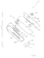
- the lighter assembly 100 includes a lighter 102, two plastics casing halves 104a, 104b, and a clip 106.
- the lighter 102 is a conventional lighter with a body 108 for containing fuel under pressure.
- a flame is produced when a button 110 is pressed to move in the direction indicated by the arrow M, which is parallel to the longitudinal axis of the lighter 102, relative to the body 108 of the lighter 102.
- the casing half 104a On the lateral edges of the casing half 104a are two narrow protruding rims 112 (of which only one is shown in Fig. 1), which co-operate with two troughs 114 (of which, again, only one is shown in Fig. 1) along two lateral edges of the casing half 104b, to allow the casing halves 104a, 104b to slide relative to each other when they are engaged with each other.
- the protruding rims 112 are received in the respective trough 114 for relative sliding movement.
- the rim 112 is shorter than the trough 114, at least by the distance required to be travelled by the button 110 for producing a flame.
- two elongate smooth pieces 118 are fixed to respective correspondingly shaped and sized parallel recesses 120 (of which only one is shown in Fig. 1) in the inner surface 116.
- the clip 106 has two oppositely spaced ledges 122 (of which only one is shown in Fig. 1) received within a rectangular aperture 124 of the casing half 104b, for fixing the clip 106 to the casing half 104b.
- the clip 106 also has two hooks 126 (of which only one is shown in Fig. 1) which, when the casing halves 104a, 104b are engaged with each other, are received within a respective channel 128 on an outer surface 130 of the casing half 104a, thus effecting engagement between said casing halves 104a, 104b, while allowing relative lengthwise sliding movement between the casing halves 104a and 104b.
- a corrugated finger pad 132 is provided on the outer surface 130 of the casing half 104a, for frictional engagement with the user's finger, e.g. thumb.
- the casing half 104a has a bent lower end 136 which, when the lighter assembly 100 is properly assembled, constitutes a stopper that acts on a lower end of the body 108 of the lighter 102.
- the casing half 104b also has a bent upper end 138 which, when the lighter assembly 100 is properly assembled, constitutes a stopper that acts on an upper surface of the button 110 of the lighter 102.
- Figs. 2 and 3 it can be seen that when the casing halves 104a, 104b and the lighter 102 are assembled to form the lighter assembly 100, most of the lighter 102 is enclosed by the casing halves 104a, 104b, except that an end 134 of the lighter 102 at which a flame is produced is exposed to the outside environment.
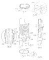
- a lighter assembly incorporated with an adapter according to a second embodiment of the present invention is shown in Figs. 5 and 6, and generally designated as 200.
- the lighter assembly 200 includes a lighter 202, two casing halves 204a, 204b, and an engagement member in the form of a closed loop 206.
- the lighter 202 is a conventional lighter with a body 208 for containing fuel under pressure. A flame is produced when a button 210 is pressed to move downwardly relative to the body 208 of the lighter 202, and parallel to the longitudinal axis of the lighter 202.
- a number of short protrusions 212 for enhancing frictional engagement of a user's finger with the casing half 204a.
- an outer surface 214 of the casing half 204b is corrugated, again for enhancing frictional engagement of a user's finger with the casing half 204b.
- Figs. 7 to 9 also show the way in which the lighter assembly 200 is assembled.
- the lighter 202 is firstly placed in the cavity of the casing half 204b, as shown in Fig. 7.
- the casing half 204a is then engaged with the casing half 204b, as shown in Fig. 8.
- the engagement loop 206 is then placed over the engaged casing halves 204a, 204b until the engagement loop 206 is engaged with the casing half 204b, as shown in Fig. 9, in a manner to be discussed below.
- Figs. 10 to 14A show various views of the casing halves 204a, 204b and engagement loop 206 as engaged with one another, in the absence of the lighter 202, for clarity purpose.
- Fig. 12 when the engagement loop 206 is engaged with the casing halves 204a, 204b, a protrusion 218 of a lip portion 220 of the engagement loop 206 is received within a hole 222 of the casing half 204b.
- Figs. 13 and 13A show the dovetail engagement between the engagement loop 206 and the casing half 204b.
- Figs. 14 and 14A show the engagement between the casing halves 204a, 204b, which allow the casing halves 204a, 204b to exhibit relative sliding movement.
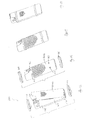
- a lighter assembly incorporated with an adapter according to a third embodiment of the present invention is shown in Figs. 15 and 18, and generally designated as 300.
- the lighter assembly 300 includes a lighter 302, two casing halves 304a, 304b, and two engagement members, each in the form of a closed loop 306.
- the lighter 302 is a conventional lighter with a body 308 for containing fuel under pressure.
- a flame is produced when a button 310 is pressed to move downwardly relative to the body 308 of the lighter 302, and parallel to the longitudinal axis of the lighter 302.
- Figs. 19 to 21A show various views of the casing halves 304a, 304b and the loops 306 as engaged with one another, in the absence of the lighter 302, for clarity purpose.
- each of the loops 306 has two protrusions 316, each to be received within one of the hole 312 on the casing half 304b, for engaging the casing halves 304a, 304b.
- the lighter assemblies 100, 200 and 300 are thus effectively child-resistant lighters at least hindering unwanted operation by small children.
- the casing halves 104a and 104b, 204a and 204b, and 304a and 304b also respectively collectively act as adapters suitable for converting an otherwise non-child-resistant lighter into a child-resistant lighter.
Abstract
Description
- This invention relates to an adapter for a lighter, which may convert a lighter into a child-resistant lighter, and a lighter incorporating such an adapter.
- There are in existence a wide variety of lighters. In order to prevent or at least hinder children from operating such lighters, various safety mechanisms have been devised. Such safety mechanisms are usually structurally complicated, and thus costly to manufacture. On the other hand, there are still manufactured lighters which are not child-resistant. There is thus a demand for mechanisms suitable for converting such lighters into ones which are child-resistant.
- It is thus an object of the present invention to provide an adapter for a lighter, and a lighter incorporating such an adapter, for mitigating the aforesaid shortcomings, and/or meeting the aforesaid demand.
- It is a further object of the present invention to provide an adapter suitable for converting an otherwise non-child-resistant lighter to a child-resistant lighter, thus assisting in preventing undesired use of lighters by children.
- According to a first aspect of the present invention, there is provided an adapter for a lighter with an actuator and a body, said adapter including at least first and second body members engageable with each other for substantially enclosing said lighter while exposing at least part of a first end of said lighter at which a flame is adapted to be produced, wherein when said body members are engaged with each other and enclosing said lighter, said body members are movable relative to each other to move said actuator of said lighter relative to said body of said lighter to produce a flame.
- According to a second aspect of the present invention, there is provided a lighter with an actuator, a body, and an adapter, wherein said adapter includes at least first and second body members engageable with each other and substantially enclosing said lighter while exposing at least part of a first end of said lighter at which a flame is adapted to be produced, wherein said body members are movable relative to each other to move said actuator relative to said body of said lighter to produce a flame.
- Embodiments of the present invention will now be described, by way of examples only, with reference to the accompanying drawings, in which:
- Fig. 1 is an exploded perspective view of a lighter incorporated with an adapter according to a first embodiment of the present invention;
- Fig. 2 is a perspective view of the lighter shown in Fig. 1, in an un-ignited configuration;
- Fig. 3 is a perspective view of the lighter shown in Fig. 2, in an ignited configuration;
- Fig. 4 is a longitudinal sectional view of the lighter shown in Fig. 2;
- Fig. 4A is an enlarged view of the encircled part in Fig. 4A;
- Fig. 5 is a perspective view of a lighter incorporated with an adapter according to a second embodiment of the present invention;
- Fig. 6 is an exploded perspective view of the lighter shown in Fig. 5;
- Fig. 7 is a perspective view of the lighter shown in Fig. 5, partly assembled;
- Fig. 8 is a further perspective view of the lighter shown in Fig. 5, partly assembled;
- Fig. 9 is a perspective view of the lighter shown in Fig. 5, fully assembled;
- Fig. 10 is a back view of the adapter shown in Fig. 5;
- Fig. 11 is a side view of the adapter shown in Fig. 10;
- Fig. 12 is an enlarged sectional view of the adapter taken along the line A-A in Fig. 10;
- Fig. 13 is a sectional view of the adapter taken along the line B-B in Fig. 10;
- Fig. 13A is an enlarged view of the encircled part in Fig. 13;
- Fig. 14 is a sectional view of the adapter taken along the line C-C in Fig. 11;
- Fig. 14A is an enlarged view of the encircled part in Fig. 14;
- Fig. 15 is a back perspective view of a lighter incorporated with an adapter according to a third embodiment of the present invention, partly assembled;
- Fig. 16 is a front perspective view of the lighter shown in Fig. 15, partly assembled;
- Fig. 17 is a front perspective view of the lighter shown in Fig. 15, fully assembled;
- Fig. 18 is a back perspective view of the lighter shown in Fig. 15, fully assembled;
- Fig. 19 is a front view of the adapter shown in Fig. 15;
- Fig. 20 is a sectional view of the adapter taken along the line D-D in Fig. 19;
- Fig. 20A is an enlarged view of the encircled part in Fig. 20;
- Fig. 21 is a sectional view of the adapter taken along the line E-E in Fig. 19; and
- Fig. 21A is an enlarged view of the encircled part in Fig. 21.
-
- A lighter assembly incorporated with an adapter according to a first embodiment of the present invention is shown in Fig. 1, and generally designated as 100. The
lighter assembly 100 includes a lighter 102, two plastics casing halves 104a, 104b, and aclip 106. The lighter 102 is a conventional lighter with abody 108 for containing fuel under pressure. A flame is produced when abutton 110 is pressed to move in the direction indicated by the arrow M, which is parallel to the longitudinal axis of the lighter 102, relative to thebody 108 of the lighter 102. - On the lateral edges of the casing half 104a are two narrow protruding rims 112 (of which only one is shown in Fig. 1), which co-operate with two troughs 114 (of which, again, only one is shown in Fig. 1) along two lateral edges of the casing half 104b, to allow the casing halves 104a, 104b to slide relative to each other when they are engaged with each other. In particular, the
protruding rims 112 are received in therespective trough 114 for relative sliding movement. Therim 112 is shorter than thetrough 114, at least by the distance required to be travelled by thebutton 110 for producing a flame. To enhance sliding movement of thebody 108 of the lighter 100 relative to theinner surface 116 of the casing half 104b, two elongatesmooth pieces 118 are fixed to respective correspondingly shaped and sized parallel recesses 120 (of which only one is shown in Fig. 1) in theinner surface 116. - As shown in Fig. 4, and more clearly in Fig. 4A, the
clip 106 has two oppositely spaced ledges 122 (of which only one is shown in Fig. 1) received within arectangular aperture 124 of the casing half 104b, for fixing theclip 106 to the casing half 104b. Theclip 106 also has two hooks 126 (of which only one is shown in Fig. 1) which, when the casing halves 104a, 104b are engaged with each other, are received within arespective channel 128 on anouter surface 130 of the casing half 104a, thus effecting engagement between said casing halves 104a, 104b, while allowing relative lengthwise sliding movement between the casing halves 104a and 104b. - In order to enhance, during use, gripping of a user's finger of the
outer surface 130 of the casing half 104a, acorrugated finger pad 132 is provided on theouter surface 130 of the casing half 104a, for frictional engagement with the user's finger, e.g. thumb. - The casing half 104a has a bent
lower end 136 which, when thelighter assembly 100 is properly assembled, constitutes a stopper that acts on a lower end of thebody 108 of the lighter 102. The casing half 104b also has a bentupper end 138 which, when thelighter assembly 100 is properly assembled, constitutes a stopper that acts on an upper surface of thebutton 110 of the lighter 102. - Turning now to Figs. 2 and 3, it can be seen that when the casing halves 104a, 104b and the lighter 102 are assembled to form the
lighter assembly 100, most of the lighter 102 is enclosed by the casing halves 104a, 104b, except that an end 134 of the lighter 102 at which a flame is produced is exposed to the outside environment. When the casing half 104a is pushed upwardly relative to the casing half 104b, because of the stopping function of the bentlower end 136 of the casing half 104a and the bentupper end 138 of the casing half 104b, the bentlower end 136 and the bentupper end 138 will be moved towards each other, such that thebutton 110 of the lighter 102 will be pushed downwardly relative to thebody 108 of the lighter 102, along a path parallel to the longitudinal axis of thebody 108, to produce a flame, as shown in Fig. 3. - A lighter assembly incorporated with an adapter according to a second embodiment of the present invention is shown in Figs. 5 and 6, and generally designated as 200. The
lighter assembly 200 includes a lighter 202, twocasing halves loop 206. The lighter 202 is a conventional lighter with abody 208 for containing fuel under pressure. A flame is produced when abutton 210 is pressed to move downwardly relative to thebody 208 of the lighter 202, and parallel to the longitudinal axis of the lighter 202. - As can be seen in Fig. 7, on an
outer surface 210 of thecasing half 204a are a number ofshort protrusions 212 for enhancing frictional engagement of a user's finger with thecasing half 204a. Similarly, as can be seen in Figs. 8 and 9, anouter surface 214 of thecasing half 204b is corrugated, again for enhancing frictional engagement of a user's finger with thecasing half 204b. Figs. 7 to 9 also show the way in which thelighter assembly 200 is assembled. - The lighter 202 is firstly placed in the cavity of the
casing half 204b, as shown in Fig. 7. Thecasing half 204a is then engaged with thecasing half 204b, as shown in Fig. 8. Theengagement loop 206 is then placed over the engagedcasing halves engagement loop 206 is engaged with thecasing half 204b, as shown in Fig. 9, in a manner to be discussed below. - Figs. 10 to 14A show various views of the
casing halves engagement loop 206 as engaged with one another, in the absence of the lighter 202, for clarity purpose. As can be seen in Fig. 12, when theengagement loop 206 is engaged with thecasing halves protrusion 218 of alip portion 220 of theengagement loop 206 is received within ahole 222 of thecasing half 204b. Figs. 13 and 13A show the dovetail engagement between theengagement loop 206 and thecasing half 204b. Figs. 14 and 14A show the engagement between the casinghalves casing halves - A lighter assembly incorporated with an adapter according to a third embodiment of the present invention is shown in Figs. 15 and 18, and generally designated as 300. The
lighter assembly 300 includes a lighter 302, twocasing halves 304a, 304b, and two engagement members, each in the form of aclosed loop 306. The lighter 302 is a conventional lighter with abody 308 for containing fuel under pressure. A flame is produced when abutton 310 is pressed to move downwardly relative to thebody 308 of the lighter 302, and parallel to the longitudinal axis of the lighter 302. As can be seen in Fig. 16, there are two pairs ofholes 312 on the casing half 304b, each pair to be engaged with one of theloops 306, in a manner to be discussed below. - Figs. 19 to 21A show various views of the
casing halves 304a, 304b and theloops 306 as engaged with one another, in the absence of the lighter 302, for clarity purpose. As can be seen more clearly in Figs. 20A and 21A, each of theloops 306 has twoprotrusions 316, each to be received within one of thehole 312 on the casing half 304b, for engaging thecasing halves 304a, 304b. - It is found in practice that the movement of the hand and fingers required to effect relative movement between, respectively, the
casing halves lighter assemblies - It should be understood that the above only illustrates examples whereby the present invention may be carried out, and that various modifications and/or alterations may be made thereto without departing from the spirit of the invention.
- It should also be understood that certain features of the invention, which are, for clarity, described in the context of separate embodiments, may be provided in combination in a single embodiment. Conversely, various features of the invention which are, for brevity, described in the context of a single embodiment, may also be provided separately or in any appropriate sub-combinations.
Claims (16)
- An adapter for a lighter with an actuator and a body, said adapter including at least first and second body members engageable with each other for substantially enclosing said lighter while exposing at least part of a first end of said lighter at which a flame is adapted to be produced, wherein when said body members are engaged with each other and enclosing said lighter, said body members are movable relative to each other to move said actuator of said lighter relative to said body of said lighter to produce a flame.
- An adapter according to Claim 1 wherein when said body members are engaged with each other and enclosing said lighter, said body members are movable relative to each other lengthwise.
- An adapter according to Claim 1 wherein when said body members are engaged with each other and enclosing said lighter, said body members are slidably movable relative to each other.
- An adapter according to Claim 1 wherein said first body member includes a stopper for acting on said actuator of said lighter, and said second body member includes a stopper for acting on a second end of said lighter.
- An adapter according to Claim 3 wherein said stoppers of said body members are movable towards each other for moving said actuator of said lighter to produce a flame.
- An adapter according to Claim 1 wherein a first finger-engagement surface is provided on an outer surface of said first body member.
- An adapter according to Claim 5 wherein a second finger-engagement surface is provided on an outer surface of said second body member.
- An adapter according to Claim 1 wherein said first body member includes at least one engagement member for engaging said first and second body members.
- An adapter according to Claim 7 wherein said first body member include a plurality of engagement members for engaging said first and second body members.
- An adapter according to Claim 7 wherein said engagement member comprises a closed loop.
- An adapter according to Claim 7 wherein at least a recess is provided in said second body member for receiving a protrusion of said engagement member for engaging said first and second body members.
- An adapter according to Claim 11 wherein said protrusion of said engagement member is movable relative to said recess.
- An adapter according to Claim 12 wherein said protrusion of said engagement member is slidably movable relative to said recess.
- An adapter according to Claim 11 wherein a plurality of recesses are provided in said second body member each for receiving a protrusion of said engagement member for engaging said first and second body members.
- A lighter with an actuator, a body, and an adapter, wherein said adapter includes at least first and second body members engageable with each other and substantially enclosing said lighter while exposing at least part of a first end of said lighter at which a flame is adapted to be produced, wherein said body members are movable relative to each other to move said actuator relative to said body of said lighter to produce a flame.
- A lighter according to Claim 15 wherein said actuator is movable relative to said body of said lighter along a path substantially parallel to a longitudinal axis of said body.
Applications Claiming Priority (2)
| Application Number | Priority Date | Filing Date | Title |
|---|---|---|---|
| CN02115308 | 2002-05-27 | ||
| CNB021153086A CN1159542C (en) | 2002-05-27 | 2002-05-27 | Lighter with slide igniting |
Publications (2)
| Publication Number | Publication Date |
|---|---|
| EP1367327A2 true EP1367327A2 (en) | 2003-12-03 |
| EP1367327A3 EP1367327A3 (en) | 2005-04-06 |
Family
ID=4743571
Family Applications (1)
| Application Number | Title | Priority Date | Filing Date |
|---|---|---|---|
| EP03253042A Withdrawn EP1367327A3 (en) | 2002-05-27 | 2003-05-15 | An adapter for a lighter and a lighter incorporating such an adapter |
Country Status (4)
| Country | Link |
|---|---|
| US (1) | US20030219688A1 (en) |
| EP (1) | EP1367327A3 (en) |
| JP (1) | JP2003343834A (en) |
| CN (1) | CN1159542C (en) |
Families Citing this family (3)
| Publication number | Priority date | Publication date | Assignee | Title |
|---|---|---|---|---|
| CN100565013C (en) * | 2006-08-11 | 2009-12-02 | 潘崔镛 | Telescopic igniter |
| CN100473904C (en) * | 2007-01-22 | 2009-04-01 | 潘崔镛 | Semi-automatic telescopic lighter |
| CN112577067B (en) * | 2020-12-22 | 2022-04-29 | 湖南省豪牌电气有限公司 | Lighter ignition detection equipment |
Citations (2)
| Publication number | Priority date | Publication date | Assignee | Title |
|---|---|---|---|---|
| JP2000055362A (en) * | 1998-07-31 | 2000-02-22 | Uehara Name Plate Kogyo Kk | Lighter cover igniter |
| US20020102506A1 (en) * | 2001-01-12 | 2002-08-01 | Adrian Berry | Lighter |
Family Cites Families (28)
| Publication number | Priority date | Publication date | Assignee | Title |
|---|---|---|---|---|
| US228325A (en) * | 1880-06-01 | Smoker s kit | ||
| US1577166A (en) * | 1926-03-16 | Eire lighter | ||
| US1024843A (en) * | 1911-05-15 | 1912-04-30 | Charles Doblin | Automatic cigar-lighter. |
| US1886461A (en) * | 1928-12-13 | 1932-11-08 | Standard Devices Inc | Pocket cigar lighter |
| NL59026C (en) * | 1936-08-29 | |||
| US2228360A (en) * | 1939-06-06 | 1941-01-14 | Arthur W Nordeck | Windproof clothespin |
| US2295747A (en) * | 1940-02-15 | 1942-09-15 | Clark Mfg Co J L | Slide cover box |
| US2433041A (en) * | 1945-05-16 | 1947-12-23 | Gonzalez Amalia Ochoa | Side action automatic lighter |
| US3362564A (en) * | 1964-10-16 | 1968-01-09 | Oscar G. Mueller | Sliding lid boxes |
| US3387912A (en) * | 1965-11-26 | 1968-06-11 | Mansei Kogyo Kk | Ignition mechanism of liquefied gas fueled lighter |
| US3408153A (en) * | 1966-04-25 | 1968-10-29 | Ishiguro Mitsuei | Gas lighter with a manually operable piezoelectric ignition device |
| US3544252A (en) * | 1968-07-31 | 1970-12-01 | Ronson Corp | Combination pocket and table lighter |
| DE1918687B2 (en) * | 1969-04-12 | 1973-08-16 | Braun Ag, 6000 Frankfurt | POCKET LIGHTER WITH AN ACTUATOR WHICH IS PART OF THE HOUSING |
| FR2158704A5 (en) * | 1971-10-29 | 1973-06-15 | Lauri Gil | |
| US3882602A (en) * | 1973-11-13 | 1975-05-13 | Julio R Polanco | Apparatus and method for mounting dental casts |
| US3942630A (en) * | 1974-11-22 | 1976-03-09 | International Tools (1973) Limited | Sliding cover safety package |
| IT1066105B (en) * | 1976-08-13 | 1985-03-04 | Sigma Tau Ind Farmaceuti | INHALER FOR SUBSTANCES IN SPRAY PACKAGE |
| US4113098A (en) * | 1977-05-25 | 1978-09-12 | Howard Charles S | Pill-dispensing and storage container |
| US4126224A (en) * | 1977-11-03 | 1978-11-21 | Laauwe Robert H | Moisture-proof and child-resistant pill box |
| DE2754639C2 (en) * | 1977-12-08 | 1979-09-13 | Rowenta-Werke Gmbh, 6050 Offenbach | Rod-shaped gas lighter |
| US4462791A (en) * | 1982-08-30 | 1984-07-31 | Richard Hayden | Fire lighter |
| US4561544A (en) * | 1983-12-28 | 1985-12-31 | Calmar, Inc. | Child resistant container |
| US5135388A (en) * | 1991-05-06 | 1992-08-04 | Pettit Frederick M | Extended-handle lighter |
| USD446718S1 (en) * | 1999-08-13 | 2001-08-21 | Glaxo Wellcome Inc. | Container for pharmaceutical tablets |
| US6099300A (en) * | 1999-09-13 | 2000-08-08 | Rice; Timothy P. | Extendable safety lighter |
| US6257876B1 (en) * | 2000-04-26 | 2001-07-10 | Hui Lin Chen | Disposable lighter holder |
| US6230889B1 (en) * | 2000-06-15 | 2001-05-15 | Sin-Hsiung Chen | Perfume bottle container |
| USD470268S1 (en) * | 2001-02-16 | 2003-02-11 | Ronson International Limited | Slide lighter |
-
2002
- 2002-05-27 CN CNB021153086A patent/CN1159542C/en not_active Expired - Fee Related
-
2003
- 2003-05-15 EP EP03253042A patent/EP1367327A3/en not_active Withdrawn
- 2003-05-23 US US10/443,836 patent/US20030219688A1/en not_active Abandoned
- 2003-05-27 JP JP2003149084A patent/JP2003343834A/en active Pending
Patent Citations (2)
| Publication number | Priority date | Publication date | Assignee | Title |
|---|---|---|---|---|
| JP2000055362A (en) * | 1998-07-31 | 2000-02-22 | Uehara Name Plate Kogyo Kk | Lighter cover igniter |
| US20020102506A1 (en) * | 2001-01-12 | 2002-08-01 | Adrian Berry | Lighter |
Non-Patent Citations (1)
| Title |
|---|
| PATENT ABSTRACTS OF JAPAN vol. 2000, no. 05, 14 September 2000 (2000-09-14) & JP 2000 055362 A (UEHARA NAME PLATE KOGYO KK; MORIKAWA SANGYO KK), 22 February 2000 (2000-02-22) * |
Also Published As
| Publication number | Publication date |
|---|---|
| CN1382941A (en) | 2002-12-04 |
| EP1367327A3 (en) | 2005-04-06 |
| JP2003343834A (en) | 2003-12-03 |
| CN1159542C (en) | 2004-07-28 |
| US20030219688A1 (en) | 2003-11-27 |
Similar Documents
| Publication | Publication Date | Title |
|---|---|---|
| AU1448502A (en) | Child resistant package with slidable tray section | |
| US5588455A (en) | Securing runner of an umbrella | |
| JPH045891Y2 (en) | ||
| US5344226A (en) | Safety device for drawers | |
| US8261374B2 (en) | Protection helmet with improved adjustable neckband | |
| RU2007105497A (en) | ADJUSTABLE HELMET SHELL | |
| US4129021A (en) | Closure device | |
| US6311373B1 (en) | Intermediate clasp for band type ornaments | |
| US4546521A (en) | Fastener for sports shoes | |
| EP0133237A1 (en) | Rake adjusting device, particularly for rear entrance ski boots | |
| EP1367327A2 (en) | An adapter for a lighter and a lighter incorporating such an adapter | |
| GB2321007A (en) | Safety runner for an umbrella | |
| GB2320922A (en) | Disc container | |
| KR930008620B1 (en) | Buckle | |
| US11759213B2 (en) | Tourniquet clip | |
| US6899504B2 (en) | Fastener | |
| GB2485455A (en) | Clip Mechanism | |
| CN110482004A (en) | Rope belt fixing device | |
| GB1586377A (en) | Crash helmet with movable visor | |
| US5513980A (en) | Method and apparatus to override the child-resistant mechanism of disposable lighters | |
| JP6199750B2 (en) | Tie fastener | |
| CN208344310U (en) | A kind of ribbon adjusting buckle of articles for children | |
| JPS5926979Y2 (en) | push button device | |
| JPH022275Y2 (en) | ||
| JP2534589Y2 (en) | Document bag opening / closing stopper |
Legal Events
| Date | Code | Title | Description |
|---|---|---|---|
| PUAI | Public reference made under article 153(3) epc to a published international application that has entered the european phase |
Free format text: ORIGINAL CODE: 0009012 |
|
| AK | Designated contracting states |
Kind code of ref document: A2 Designated state(s): AT BE BG CH CY CZ DE DK EE ES FI FR GB GR HU IE IT LI LU MC NL PT RO SE SI SK TR |
|
| AX | Request for extension of the european patent |
Extension state: AL LT LV MK |
|
| PUAL | Search report despatched |
Free format text: ORIGINAL CODE: 0009013 |
|
| AK | Designated contracting states |
Kind code of ref document: A3 Designated state(s): AT BE BG CH CY CZ DE DK EE ES FI FR GB GR HU IE IT LI LU MC NL PT RO SE SI SK TR |
|
| AX | Request for extension of the european patent |
Extension state: AL LT LV MK |
|
| AKX | Designation fees paid | ||
| REG | Reference to a national code |
Ref country code: DE Ref legal event code: 8566 |
|
| STAA | Information on the status of an ep patent application or granted ep patent |
Free format text: STATUS: THE APPLICATION IS DEEMED TO BE WITHDRAWN |
|
| 18D | Application deemed to be withdrawn |
Effective date: 20051007 |