EP1367281A1 - Butée de débrayage avec élément d'attaque rapporté - Google Patents
Butée de débrayage avec élément d'attaque rapporté Download PDFInfo
- Publication number
- EP1367281A1 EP1367281A1 EP03291171A EP03291171A EP1367281A1 EP 1367281 A1 EP1367281 A1 EP 1367281A1 EP 03291171 A EP03291171 A EP 03291171A EP 03291171 A EP03291171 A EP 03291171A EP 1367281 A1 EP1367281 A1 EP 1367281A1
- Authority
- EP
- European Patent Office
- Prior art keywords
- bearing
- rotating ring
- ring
- diaphragm
- clutch
- Prior art date
- Legal status (The legal status is an assumption and is not a legal conclusion. Google has not performed a legal analysis and makes no representation as to the accuracy of the status listed.)
- Granted
Links
Images


Classifications
-
- F—MECHANICAL ENGINEERING; LIGHTING; HEATING; WEAPONS; BLASTING
- F16—ENGINEERING ELEMENTS AND UNITS; GENERAL MEASURES FOR PRODUCING AND MAINTAINING EFFECTIVE FUNCTIONING OF MACHINES OR INSTALLATIONS; THERMAL INSULATION IN GENERAL
- F16D—COUPLINGS FOR TRANSMITTING ROTATION; CLUTCHES; BRAKES
- F16D23/00—Details of mechanically-actuated clutches not specific for one distinct type
- F16D23/12—Mechanical clutch-actuating mechanisms arranged outside the clutch as such
- F16D23/14—Clutch-actuating sleeves or bearings; Actuating members directly connected to clutch-actuating sleeves or bearings
- F16D23/143—Arrangements or details for the connection between the release bearing and the diaphragm
-
- F—MECHANICAL ENGINEERING; LIGHTING; HEATING; WEAPONS; BLASTING
- F16—ENGINEERING ELEMENTS AND UNITS; GENERAL MEASURES FOR PRODUCING AND MAINTAINING EFFECTIVE FUNCTIONING OF MACHINES OR INSTALLATIONS; THERMAL INSULATION IN GENERAL
- F16D—COUPLINGS FOR TRANSMITTING ROTATION; CLUTCHES; BRAKES
- F16D23/00—Details of mechanically-actuated clutches not specific for one distinct type
- F16D23/12—Mechanical clutch-actuating mechanisms arranged outside the clutch as such
- F16D23/14—Clutch-actuating sleeves or bearings; Actuating members directly connected to clutch-actuating sleeves or bearings
- F16D23/143—Arrangements or details for the connection between the release bearing and the diaphragm
- F16D23/144—With a disengaging thrust-ring distinct from the release bearing, and secured to the diaphragm
- F16D23/146—Arrangements for the connection between the thrust-ring and the release bearing
Definitions
- the present invention relates to the field of stops clutch intended to act on the diaphragm of a clutch, in particular for a motor vehicle.
- the invention applies to clutch release bearings comprising a bearing of which one of the rings is rotating and the other ring is fixed.
- a self-centering element is generally interposed between the ring fixed bearing and operating element, said self-centering element ensuring the connection between these two parts while authorizing, by its elasticity, a relative radial displacement between said two parts.
- the bearing thus actuates the clutch by through its rotating ring according to a defined action diameter by the contact area between diaphragm and rotating bearing ring stop, whether solid or sheet metal.
- Fingertips diaphragm in contact with the rotating ring of the stopper can have a flat or well rounded shape and the contact surface corresponding of the rotating ring can also be shaped rounded or flat.
- the thrust bearing can self-center in operation on the diaphragm thanks to the self-centering element and a radial clearance existing between the operating member and the fixed ring of the thrust bearing.
- the attack surface of a given stop therefore has a useful action diameter which is specific to it and is generally not able to operate with different clutches from each other, either by their action diameter, or by the shape of the ends of diaphragm fingers.
- I1 therefore need rotating stop rings adapted to each series of clutch action diameters and also to the shape of the ends of the diaphragm fingers. This leads to a multiplication of manufacturing variants of clutch release bearings and increased manufacturing, management and storage costs.
- Document EP-A-0 892 188 proposes a clutch release bearing with attached attack surface comprising an attack flange secured to the rotating ring and intended to come into contact with the diaphragm and an axially elastic connecting member provided with windows cooperating with protrusions of the leading flange forming hooks.
- the attack flange is centered on the ring rotating bearing.
- the connecting member comprises a base circular in the shape of a washer which comes to bear on the rotating ring axially opposite the leading flange.
- the present invention aims to remedy the drawbacks of devices described above by proposing a simple, economical stop, with few parts and can incorporate a ring bearing in sheet metal as well as a standard bearing with solid rings.
- the clutch release device is of the type comprising a rolling bearing fitted with a non-rotating ring and a rotating ring, and capable of acting on a diaphragm of clutch mechanism.
- the clutch release bearing device includes an element sheet metal integral with the rotating ring and designed to enter contact with the diaphragm.
- the device includes means for retaining the driving element on the rotating ring. Said means of retainers are integral with the attack element. We thus benefit an element of attack ensuring itself its maintenance on the ring rotating the thrust bearing.
- the clutch release bearing is therefore simple and economical structure and easy assembly.
- the means of restraints are elastic.
- the retaining means include axial tongues provided at their end with axial retaining means on the rotating ring of the bearing.
- the means of axial retainers include legs folded radially, in particular towards the inside. Legs can be obtained by partial cutting axial and folding tabs.
- the element comprises centering tabs on the rotating ring of the thrust bearing.
- the outer ring of the bearing can be made of sheet metal stamped without removing chips, or be of the solid type produced by machining.
- the non-rotating ring will generally be the same type as the rotating ring.
- the invention also provides an attack element for a stop declutching unit comprising a rolling bearing provided with a non- rotating and a rotating ring, said sheet metal element being provided to be secured to the rotating ring and to come into contact with a clutch diaphragm.
- the element is in one piece retaining means capable of cooperating with the rotating ring of the thrust bearing.
- This provides a light weight thrust bearing, standardized manufacturing and provided with an element of attack allowing adapting the same bearing to different types of diaphragm Clutch.
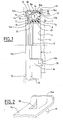
- the stopper declutching unit includes a rolling bearing 1 mounted on a operation 2 by means of a self-centering member 3.
- the element of operation 2 comprises a tubular part 4 provided at its end free from an annular rim 5 projecting outwards and from a surface radial 6 formed at the other end of the tubular part 4.
- the bearing 1 is mounted in contact with the radial surface 6 of the operating element 2.
- the bearing 1 comprises a ring non-rotating inner 7, a rotating outer ring 8 made of stamped sheet metal, a row of rolling elements 9 held by a cage 10 and disposed between the inner 7 and outer 8 rings.
- the ring interior 7 is provided with a radial portion 7a which comes into contact with the radial surface 6 of the operating element 2.
- the self-centering member 3 is disposed in the bore of the inner ring 7 and includes a plurality of flexible teeth 11 radially and extending towards the tubular part 5 of the operating element 2.
- the bearing 1 can therefore self-center by relative to the operating element 2 by causing the bending of the teeth 11 of the self-centering member 3.
- a sealing lip 12, issuing of the self-centering member 3, extends axially outwards and rubs against the rotating outer ring 8.
- An organ seal 13 is also provided at the other end of the bearing 1.
- the rotating outer ring 8 comprises a tubular portion 8a adjacent to the runway 8b provided for the row of elements wheels 9, and in contact with the sealing member 13. From the side axially opposite the operating element 2, the outer ring 8 comprises a substantially radial portion 8c extending towards inside.
- the radial portion 8c is covered by a driving element 14, made of stamped sheet metal, and comprising a substantially radial 14a applying at least in part against the radial portion 8c of the outer ring 8, a circular toroidal bead 14b projecting axially outwardly disposed at the large diameter end of the radial portion 14a, and forming a contact surface with the fingers 15 a clutch diaphragm.
- the sealing member 13 comprises a thin sheet element and a flexible element in the shape of a washer 13c disposed between the sheet metal element and the free end of the tubular portion 8a of the ring 8.
- the element in sheet includes a fixing portion 13a surrounding the surface outside of the tubular portion 8a of the rotating ring 8 with concordance of form.
- the fixing portion 13a has a shape generally axial.
- the sheet metal element also includes a portion seal 13b forming a narrow passage with the ring not rotating 7.
- the sealing portion 13b has a shape generally radial and extends from the end of the portion of fixing 13a adjacent to the free end of the tubular portion 8a, towards the non-rotating ring 7.
- the seal between the tubular portion 8a and the sheet metal element is provided by the flexible element 13c.
- the fingers 15 are flat and the bead 14b is shaped rounded in axial section for good cooperation between these two elements.
- the attack element 14 extends beyond the bead 14b by three radial protuberances forming tongues 16 oriented axially opposite the fingers 15 of the diaphragm, and by three others radial protuberances forming tongues 17 also oriented axially opposite the fingers 15 of the diaphragm.
- Tabs 16 and the tongues 17 are circumferentially regularly distributed, the tongues 16 alternating with the tongues 17.
- the tongues 16 are of axial length greater than that of bearing 1 and protrude axially beyond the radial surface 6 of the driving element 2.
- a rectangular tab 19 is formed by partial cutting and folding inward of the free end 16a of each tab 16. After cutting and folding the tab 19, it remains on the tongue 16 a window 18 delimited on three sides by the cutting edges forming a "U" and on the fourth side by the internal face of the tab 19.
- the width of window 18 is between 1/3 and 2/3 of the width of the tongue 16.
- the free end 16a is folded outwards according to a angle of the order of 70 to 90 ° relative to the general axis of the tongue 16.
- the tab 19 is therefore directed radially inwards and comes in bearing against the sealing member 13 secured to the tubular portion 8a of the outer ring 8.
- the tongues 16, provided with their lugs 19, thus ensure the axial retention of the attack element intended to be in contact with a clutch diaphragm, with bearing 1.
- the tongues 17 are of axial length less than that of the bearing 1 and come into contact with the outer surface of the bearing 1 formed by a portion of the sealing member 13 enveloping the tubular portion 8a of the outer ring 8.
- the centering tabs 17 are inclined radially towards the outer ring 8 and are mounted thereon with a very slight diametral interference in order to remain in permanent contact with the outer surface of said ring 8, here formed by the outer surface of the sealing member 13, and thus ensure precise centering.
- the retaining tabs 16 are provided with a slight radial offset with respect to said outer ring 8.
- the retaining tabs 19 are removed from the sheet of the retaining tabs 16 by punching, and are folded radially.
- forming the retaining tabs 19 by other methods, for example by folding the free end of the tabs 16.
- the retaining tabs 16 flex radially towards the exterior during the passage of said tabs on the outer ring 8, then once the retaining tabs 19 have passed behind the face rear of the sealing member 13, said retaining tabs 16 resiliently close radially towards the outer ring 8 and thus allow the retaining tabs 19 to cooperate with the rear face of the sealing member 13 and perform their function of axial restraint.
- the centering tabs 17 come radially supported on the periphery of the outer ring 8, or in the case shown on the periphery of the sealing member 13, and the frontal annular part 14a of the attached attack element comes in support by its internal face on the front face of the rotating ring 8 of the bearing 1.
- the attack element 14 can be manufactured very economical from a steel strip, by cutting, stamping and folding, said attack element once formed undergoing treatment thermal hardening limiting wear due to contact with fingers 15 of the clutch diaphragm.
- FIG. 4 illustrates an embodiment of the invention suitable for a standard conventional bearing with solid rings.
- the bearing 20 includes a non-rotating inner ring 21, a rotating outer ring 22, a row of rolling elements 23, here balls, arranged between raceways formed on the inner 21 and outer 22 rings and held by a cage 24, and sealing elements 25 and 26 mounted on either side of the rolling elements 23 and closing off the space between the inner rings 21 and exterior 22.
- the sealing elements 25 and 26 are identical.
- the inner 21 and outer 22 rings are of the massive type and have a raceway forming a concavity by ratio, respectively, to the outer surface and the inner surface inner 21 and outer 22 rings.
- the outer ring 22 includes radial front surfaces 22a and 22b, coplanar with the corresponding radial front surfaces 21a and 21b of the ring interior 21.
- solid rings we mean rings that are not obtained from a metal sheet but from annular blanks forged, rolled or turned, the final shapes and dimensions being obtained by machining processes with chip removal.
- the driving element 27 comprises a radial portion 27a directed inward and intended to be in contact with fingers 28 slightly convex, with a clutch diaphragm.
- the element attack 27 further comprises a short tubular portion 27b directed away from the diaphragm fingers 28 from the end of large diameter of the radial portion 27a, and a radial portion additional 27c relatively short and extending radially towards the exterior from the end of the tubular portion 27b opposite the radial portion 27a.
- the additional radial portion 27c thus offers a radial surface on which rests the front face 22a of the outer ring 22 avoiding any contact between the rest of the element 27, in particular the radial portion 27a, and the element 26 or the inner ring 21.
- the attack element 27 is completed like the element 14 by retaining tabs 29 and centering 30 analogous to the tongues 16 and 17 of the previous embodiments.
- the centering tabs 30 are of curved shape and come in contact with the tubular peripheral surface of the outer ring 22.
- the tabs 32 formed at the free end 29a of the retaining tabs 29 are in contact with the radial front surface 22b of the ring 22.
- it can work with a large diameter diaphragm, the radial portion 27a could be folded back to face outward.
- the attack element added allows, very economically, to equip a sheet metal stop existing so that it can be used with a diaphragm diameter for which it had not been originally planned, thus avoiding the development and manufacture of a new custom bearing.
- the attached attack element also transforms extremely quickly a standard conventional ring bearing massive, mass-produced, in a clutch release bearing specific and adapted to a particular diameter of diaphragm.
- the insert element is economical to manufacture, easy to set up with a simple axial movement and does not modify the play initial internal bearing. Indeed, the attack element cooperates with the outer ring without exerting excessive stress on it, stress which could present a risk of deformation of the ring external and therefore modification of the internal clearance of the bearing.
Landscapes
- Engineering & Computer Science (AREA)
- General Engineering & Computer Science (AREA)
- Mechanical Engineering (AREA)
- Mechanical Operated Clutches (AREA)
Abstract
Description
- la figure 1 est une vue de côté, partiellement en coupe axiale et partiellement en élévation, d'une butée d'embrayage selon un aspect de l'invention ;
- la figure 2 est une vue de détail d'une patte de collerette de la figure 1 ;
- la figure 3 est une vue arrière en élévation de la butée de débrayage de la figure 1 ; et
- la figure 4 est une vue en coupe axiale d'un autre mode de réalisation de butée de débrayage selon l'invention.
Claims (9)
- Dispositif de butée de débrayage, du type comprenant un palier à roulement (1) muni d'une bague non tournante (7) et d'une bague tournante (8), ledit dispositif étant capable d'agir sur un diaphragme de mécanisme d'embrayage, et comprenant un élément d'attaque (14) en tôle solidaire de la bague tournante et prévu pour entrer en contact avec le diaphragme, ledit dispositif comprenant des moyens de retenue de l'élément d'attaque sur la bague tournante, caractérisé par le fait que lesdits moyens de retenue sont monoblocs avec l'élément d'attaque.
- Dispositif selon la revendication 1, caractérisé par le fait que l'élément d'attaque comprend des languettes axiales pourvues à leur extrémité de moyens de retenue axiale sur la bague tournante du roulement.
- Dispositif selon la revendication 2, caractérisé par le fait que les moyens de retenue comprennent des pattes (19) pliées vers l'intérieur.
- Dispositif selon la revendication 3, caractérisé par le fait que les pattes sont obtenues par découpe partielle de la languette (16).
- Dispositif selon la revendication 3 ou 4, caractérisé par le fait que les pattes sont pliées.
- Dispositif selon l'une quelconque des revendications précédentes, caractérisé par le fait que l'élément d'attaque comprend des languettes de centrage (17).
- Dispositif selon l'une quelconque des revendications précédentes, caractérisé par le fait que la bague extérieure (8) est en tôle emboutie.
- Dispositif selon l'une quelconque des revendications 1 à 6, caractérisé par le fait que la bague extérieure est massive.
- Elément d'attaque pour butée de débrayage du type comprenant un palier à roulement muni d'une bague non tournante et d'une bague tournante, ledit élément d'attaque réalisé en tôle étant capable d'agir sur un diaphragme de mécanisme d'embrayage tout en étant solidaire de la bague tournante, caractérisé par le fait qu'il comprend, de façon monobloc, des moyens de retenue sur la bague tournante.
Applications Claiming Priority (2)
| Application Number | Priority Date | Filing Date | Title |
|---|---|---|---|
| FR0206516 | 2002-05-28 | ||
| FR0206516A FR2840378B1 (fr) | 2002-05-28 | 2002-05-28 | Butee de debrayage avec element d'attaque rapporte |
Publications (2)
| Publication Number | Publication Date |
|---|---|
| EP1367281A1 true EP1367281A1 (fr) | 2003-12-03 |
| EP1367281B1 EP1367281B1 (fr) | 2006-11-15 |
Family
ID=29415132
Family Applications (1)
| Application Number | Title | Priority Date | Filing Date |
|---|---|---|---|
| EP20030291171 Expired - Lifetime EP1367281B1 (fr) | 2002-05-28 | 2003-05-20 | Butée de débrayage avec élément d'attaque rapporté |
Country Status (3)
| Country | Link |
|---|---|
| EP (1) | EP1367281B1 (fr) |
| DE (1) | DE60309624T2 (fr) |
| FR (1) | FR2840378B1 (fr) |
Cited By (6)
| Publication number | Priority date | Publication date | Assignee | Title |
|---|---|---|---|---|
| FR2894000A1 (fr) * | 2005-11-25 | 2007-06-01 | Skf Ab | Procede de fabrication d'un palier a roulement, palier a roulement et butee axiale |
| FR2916502A1 (fr) * | 2007-05-25 | 2008-11-28 | Snr Roulements Sa | Butee d'embrayage comprenant une bague d'actionnement rotulante |
| FR2973461A1 (fr) * | 2011-03-29 | 2012-10-05 | Renault Sa | Dispositif de commande d'embrayage a recepteur concentrique mecanique |
| CN105927667A (zh) * | 2015-02-27 | 2016-09-07 | 斯凯孚公司 | 包括抗磨损圈的滚动轴承 |
| CN110056570A (zh) * | 2018-01-18 | 2019-07-26 | 斯凯孚公司 | 球轴承、包括该轴承的离合器止推轴承装置和传动系系统 |
| CN110206815A (zh) * | 2018-02-28 | 2019-09-06 | 斯凯孚公司 | 球轴承、包括该轴承的离合器止推轴承装置和传动系系统 |
Families Citing this family (1)
| Publication number | Priority date | Publication date | Assignee | Title |
|---|---|---|---|---|
| FR2883347B1 (fr) | 2005-03-15 | 2007-06-01 | Skf Ab | Butee de debrayage |
Citations (3)
| Publication number | Priority date | Publication date | Assignee | Title |
|---|---|---|---|---|
| FR2215112A5 (fr) * | 1973-01-24 | 1974-08-19 | Ferodo Sa | |
| US4629049A (en) * | 1982-08-03 | 1986-12-16 | Valeo | Sustained self-centering clutch release bearing for motor vehicles |
| EP0892188A1 (fr) | 1997-07-15 | 1999-01-20 | Skf France | Butée de débrayage avec surface d'attaque rapportée |
-
2002
- 2002-05-28 FR FR0206516A patent/FR2840378B1/fr not_active Expired - Fee Related
-
2003
- 2003-05-20 DE DE2003609624 patent/DE60309624T2/de not_active Expired - Lifetime
- 2003-05-20 EP EP20030291171 patent/EP1367281B1/fr not_active Expired - Lifetime
Patent Citations (3)
| Publication number | Priority date | Publication date | Assignee | Title |
|---|---|---|---|---|
| FR2215112A5 (fr) * | 1973-01-24 | 1974-08-19 | Ferodo Sa | |
| US4629049A (en) * | 1982-08-03 | 1986-12-16 | Valeo | Sustained self-centering clutch release bearing for motor vehicles |
| EP0892188A1 (fr) | 1997-07-15 | 1999-01-20 | Skf France | Butée de débrayage avec surface d'attaque rapportée |
Cited By (8)
| Publication number | Priority date | Publication date | Assignee | Title |
|---|---|---|---|---|
| FR2894000A1 (fr) * | 2005-11-25 | 2007-06-01 | Skf Ab | Procede de fabrication d'un palier a roulement, palier a roulement et butee axiale |
| FR2916502A1 (fr) * | 2007-05-25 | 2008-11-28 | Snr Roulements Sa | Butee d'embrayage comprenant une bague d'actionnement rotulante |
| FR2973461A1 (fr) * | 2011-03-29 | 2012-10-05 | Renault Sa | Dispositif de commande d'embrayage a recepteur concentrique mecanique |
| CN105927667A (zh) * | 2015-02-27 | 2016-09-07 | 斯凯孚公司 | 包括抗磨损圈的滚动轴承 |
| CN110056570A (zh) * | 2018-01-18 | 2019-07-26 | 斯凯孚公司 | 球轴承、包括该轴承的离合器止推轴承装置和传动系系统 |
| CN110056570B (zh) * | 2018-01-18 | 2022-06-07 | 斯凯孚公司 | 球轴承、包括该轴承的离合器止推轴承装置和传动系系统 |
| CN110206815A (zh) * | 2018-02-28 | 2019-09-06 | 斯凯孚公司 | 球轴承、包括该轴承的离合器止推轴承装置和传动系系统 |
| CN110206815B (zh) * | 2018-02-28 | 2022-06-07 | 斯凯孚公司 | 球轴承、包括该轴承的离合器止推轴承装置和传动系系统 |
Also Published As
| Publication number | Publication date |
|---|---|
| FR2840378A1 (fr) | 2003-12-05 |
| DE60309624D1 (de) | 2006-12-28 |
| FR2840378B1 (fr) | 2005-08-26 |
| DE60309624T2 (de) | 2007-09-06 |
| EP1367281B1 (fr) | 2006-11-15 |
Similar Documents
| Publication | Publication Date | Title |
|---|---|---|
| EP1489327B1 (fr) | Butée de débrayage et procédé de montage | |
| WO1998026189A1 (fr) | Palier a roulement de colonne de direction pour vehicules automobiles | |
| FR2889278A1 (fr) | Dispositif de galet pour courroie | |
| FR2860847A1 (fr) | Dispositif de butee de debrayage | |
| EP1080317B1 (fr) | Butee de debrayage a auto-alignement par manchon | |
| FR2961280A1 (fr) | Dispositif de butee de debrayage comprenant une bague d'usure. | |
| EP0806581B1 (fr) | Dispositif de butée d'embrayage à rondelle élastique | |
| EP1367281B1 (fr) | Butée de débrayage avec élément d'attaque rapporté | |
| EP0892188B1 (fr) | Butée de débrayage avec surface d'attaque rapportée | |
| EP0773384B1 (fr) | Flasque de protection pour roulement, roulement associé et procédé de fabrication d'une bague de roulement équipée d'un flasque de protection | |
| EP1264113B1 (fr) | Palier a roulement de colonne de direction pour vehicules automobiles | |
| FR2748535A1 (fr) | Roulement de butee d'embrayage avec cage a retenue axiale | |
| EP1409883B1 (fr) | Palier a roulement de colonne de direction pour vehicule automobile | |
| FR2760057A1 (fr) | Dispositif de roue libre a flasque de retenue et procede de mise en place du flasque | |
| EP1420184A1 (fr) | Butée de débrayage avec élément d'attaque rapporté et procédé de fabrication | |
| FR2995375A1 (fr) | Butee d'embrayage-debrayage et vehicule automobile equipe d'une telle butee | |
| FR2782758A1 (fr) | Palier a roulement | |
| FR3001513A1 (fr) | Dispositif de butee d'embrayage-debrayage, systeme de commande d'embrayage-debrayage equipe d'un tel dispositif et vehicule automobile equipe d'un tel dispositif | |
| EP0836685B1 (fr) | Montage de butee de debrayage | |
| EP0926375B1 (fr) | Butée de débrayage avec agrafes latérales de guidage et de liaison | |
| FR2876170A1 (fr) | Butee de debrayage autocentreuse et procede de montage | |
| EP0736146B1 (fr) | Butee de debrayage | |
| FR2841522A1 (fr) | Colonne de direction a moyens de retenue de roulement, procede de realisation, ensemble de direction et vehicule automobile correspondants | |
| FR2747441A1 (fr) | Montage de butee de debrayage | |
| FR2772853A1 (fr) | Butee de debrayage avec agrafes laterales de guidage et de liaison |
Legal Events
| Date | Code | Title | Description |
|---|---|---|---|
| PUAI | Public reference made under article 153(3) epc to a published international application that has entered the european phase |
Free format text: ORIGINAL CODE: 0009012 |
|
| AK | Designated contracting states |
Kind code of ref document: A1 Designated state(s): AT BE BG CH CY CZ DE DK EE ES FI FR GB GR HU IE IT LI LU MC NL PT RO SE SI SK TR |
|
| AX | Request for extension of the european patent |
Extension state: AL LT LV MK |
|
| 17P | Request for examination filed |
Effective date: 20040107 |
|
| AKX | Designation fees paid |
Designated state(s): DE FR GB IT |
|
| GRAP | Despatch of communication of intention to grant a patent |
Free format text: ORIGINAL CODE: EPIDOSNIGR1 |
|
| GRAS | Grant fee paid |
Free format text: ORIGINAL CODE: EPIDOSNIGR3 |
|
| GRAA | (expected) grant |
Free format text: ORIGINAL CODE: 0009210 |
|
| AK | Designated contracting states |
Kind code of ref document: B1 Designated state(s): DE FR GB IT |
|
| REG | Reference to a national code |
Ref country code: GB Ref legal event code: FG4D Free format text: NOT ENGLISH |
|
| GBT | Gb: translation of ep patent filed (gb section 77(6)(a)/1977) |
Effective date: 20061115 |
|
| REF | Corresponds to: |
Ref document number: 60309624 Country of ref document: DE Date of ref document: 20061228 Kind code of ref document: P |
|
| PLBE | No opposition filed within time limit |
Free format text: ORIGINAL CODE: 0009261 |
|
| STAA | Information on the status of an ep patent application or granted ep patent |
Free format text: STATUS: NO OPPOSITION FILED WITHIN TIME LIMIT |
|
| 26N | No opposition filed |
Effective date: 20070817 |
|
| PGFP | Annual fee paid to national office [announced via postgrant information from national office to epo] |
Ref country code: GB Payment date: 20130531 Year of fee payment: 11 |
|
| PGFP | Annual fee paid to national office [announced via postgrant information from national office to epo] |
Ref country code: FR Payment date: 20130621 Year of fee payment: 11 Ref country code: IT Payment date: 20130527 Year of fee payment: 11 |
|
| PGFP | Annual fee paid to national office [announced via postgrant information from national office to epo] |
Ref country code: DE Payment date: 20130731 Year of fee payment: 11 |
|
| REG | Reference to a national code |
Ref country code: DE Ref legal event code: R119 Ref document number: 60309624 Country of ref document: DE |
|
| GBPC | Gb: european patent ceased through non-payment of renewal fee |
Effective date: 20140520 |
|
| REG | Reference to a national code |
Ref country code: DE Ref legal event code: R119 Ref document number: 60309624 Country of ref document: DE Effective date: 20141202 |
|
| REG | Reference to a national code |
Ref country code: FR Ref legal event code: ST Effective date: 20150130 |
|
| PG25 | Lapsed in a contracting state [announced via postgrant information from national office to epo] |
Ref country code: DE Free format text: LAPSE BECAUSE OF NON-PAYMENT OF DUE FEES Effective date: 20141202 Ref country code: IT Free format text: LAPSE BECAUSE OF NON-PAYMENT OF DUE FEES Effective date: 20140520 |
|
| PG25 | Lapsed in a contracting state [announced via postgrant information from national office to epo] |
Ref country code: FR Free format text: LAPSE BECAUSE OF NON-PAYMENT OF DUE FEES Effective date: 20140602 Ref country code: GB Free format text: LAPSE BECAUSE OF NON-PAYMENT OF DUE FEES Effective date: 20140520 |