EP1367273A2 - Sliding bearing for radial and axial loads - Google Patents
Sliding bearing for radial and axial loads Download PDFInfo
- Publication number
- EP1367273A2 EP1367273A2 EP03011683A EP03011683A EP1367273A2 EP 1367273 A2 EP1367273 A2 EP 1367273A2 EP 03011683 A EP03011683 A EP 03011683A EP 03011683 A EP03011683 A EP 03011683A EP 1367273 A2 EP1367273 A2 EP 1367273A2
- Authority
- EP
- European Patent Office
- Prior art keywords
- ring
- bearing
- axial
- bearing according
- bearing ring
- Prior art date
- Legal status (The legal status is an assumption and is not a legal conclusion. Google has not performed a legal analysis and makes no representation as to the accuracy of the status listed.)
- Granted
Links
- 125000006850 spacer group Chemical group 0.000 claims description 10
- 239000000314 lubricant Substances 0.000 claims description 8
- 230000003993 interaction Effects 0.000 claims description 3
- 239000012791 sliding layer Substances 0.000 claims 1
- 238000000576 coating method Methods 0.000 description 2
- 238000009826 distribution Methods 0.000 description 2
- 238000004026 adhesive bonding Methods 0.000 description 1
- 230000015572 biosynthetic process Effects 0.000 description 1
- 239000011248 coating agent Substances 0.000 description 1
- 230000000295 complement effect Effects 0.000 description 1
- 238000011109 contamination Methods 0.000 description 1
- 238000009434 installation Methods 0.000 description 1
- 238000004519 manufacturing process Methods 0.000 description 1
- 239000000463 material Substances 0.000 description 1
- 238000003860 storage Methods 0.000 description 1
Images

Classifications
-
- F—MECHANICAL ENGINEERING; LIGHTING; HEATING; WEAPONS; BLASTING
- F16—ENGINEERING ELEMENTS AND UNITS; GENERAL MEASURES FOR PRODUCING AND MAINTAINING EFFECTIVE FUNCTIONING OF MACHINES OR INSTALLATIONS; THERMAL INSULATION IN GENERAL
- F16C—SHAFTS; FLEXIBLE SHAFTS; ELEMENTS OR CRANKSHAFT MECHANISMS; ROTARY BODIES OTHER THAN GEARING ELEMENTS; BEARINGS
- F16C17/00—Sliding-contact bearings for exclusively rotary movement
- F16C17/10—Sliding-contact bearings for exclusively rotary movement for both radial and axial load
-
- F—MECHANICAL ENGINEERING; LIGHTING; HEATING; WEAPONS; BLASTING
- F03—MACHINES OR ENGINES FOR LIQUIDS; WIND, SPRING, OR WEIGHT MOTORS; PRODUCING MECHANICAL POWER OR A REACTIVE PROPULSIVE THRUST, NOT OTHERWISE PROVIDED FOR
- F03D—WIND MOTORS
- F03D7/00—Controlling wind motors
- F03D7/02—Controlling wind motors the wind motors having rotation axis substantially parallel to the air flow entering the rotor
- F03D7/0204—Controlling wind motors the wind motors having rotation axis substantially parallel to the air flow entering the rotor for orientation in relation to wind direction
-
- F—MECHANICAL ENGINEERING; LIGHTING; HEATING; WEAPONS; BLASTING
- F03—MACHINES OR ENGINES FOR LIQUIDS; WIND, SPRING, OR WEIGHT MOTORS; PRODUCING MECHANICAL POWER OR A REACTIVE PROPULSIVE THRUST, NOT OTHERWISE PROVIDED FOR
- F03D—WIND MOTORS
- F03D80/00—Details, components or accessories not provided for in groups F03D1/00 - F03D17/00
- F03D80/70—Bearing or lubricating arrangements
-
- F—MECHANICAL ENGINEERING; LIGHTING; HEATING; WEAPONS; BLASTING
- F05—INDEXING SCHEMES RELATING TO ENGINES OR PUMPS IN VARIOUS SUBCLASSES OF CLASSES F01-F04
- F05B—INDEXING SCHEME RELATING TO WIND, SPRING, WEIGHT, INERTIA OR LIKE MOTORS, TO MACHINES OR ENGINES FOR LIQUIDS COVERED BY SUBCLASSES F03B, F03D AND F03G
- F05B2240/00—Components
- F05B2240/10—Stators
- F05B2240/14—Casings, housings, nacelles, gondels or the like, protecting or supporting assemblies there within
-
- F—MECHANICAL ENGINEERING; LIGHTING; HEATING; WEAPONS; BLASTING
- F16—ENGINEERING ELEMENTS AND UNITS; GENERAL MEASURES FOR PRODUCING AND MAINTAINING EFFECTIVE FUNCTIONING OF MACHINES OR INSTALLATIONS; THERMAL INSULATION IN GENERAL
- F16C—SHAFTS; FLEXIBLE SHAFTS; ELEMENTS OR CRANKSHAFT MECHANISMS; ROTARY BODIES OTHER THAN GEARING ELEMENTS; BEARINGS
- F16C2300/00—Application independent of particular apparatuses
- F16C2300/10—Application independent of particular apparatuses related to size
- F16C2300/14—Large applications, e.g. bearings having an inner diameter exceeding 500 mm
-
- F—MECHANICAL ENGINEERING; LIGHTING; HEATING; WEAPONS; BLASTING
- F16—ENGINEERING ELEMENTS AND UNITS; GENERAL MEASURES FOR PRODUCING AND MAINTAINING EFFECTIVE FUNCTIONING OF MACHINES OR INSTALLATIONS; THERMAL INSULATION IN GENERAL
- F16C—SHAFTS; FLEXIBLE SHAFTS; ELEMENTS OR CRANKSHAFT MECHANISMS; ROTARY BODIES OTHER THAN GEARING ELEMENTS; BEARINGS
- F16C2360/00—Engines or pumps
- F16C2360/31—Wind motors
-
- Y—GENERAL TAGGING OF NEW TECHNOLOGICAL DEVELOPMENTS; GENERAL TAGGING OF CROSS-SECTIONAL TECHNOLOGIES SPANNING OVER SEVERAL SECTIONS OF THE IPC; TECHNICAL SUBJECTS COVERED BY FORMER USPC CROSS-REFERENCE ART COLLECTIONS [XRACs] AND DIGESTS
- Y02—TECHNOLOGIES OR APPLICATIONS FOR MITIGATION OR ADAPTATION AGAINST CLIMATE CHANGE
- Y02E—REDUCTION OF GREENHOUSE GAS [GHG] EMISSIONS, RELATED TO ENERGY GENERATION, TRANSMISSION OR DISTRIBUTION
- Y02E10/00—Energy generation through renewable energy sources
- Y02E10/70—Wind energy
- Y02E10/72—Wind turbines with rotation axis in wind direction
Definitions
- the invention relates to a slide bearing for the axial and radial mounting of two objects rotatable relative to each other.
- Such a plain bearing is known from DE 100 12 773 A1.
- the known Slide bearing has axially acting and radially acting sliding surfaces that are vertical are oriented to the axial direction or perpendicular to the radial direction.
- the axial acting sliding surfaces can be more or less by means of hydraulic pistons are strongly pressed against their counter surfaces.
- the invention is therefore based on the object of acting radially and axially Specify plain bearings whose sliding surfaces are easily adjustable and with the least possible effort can be achieved.
- the slide bearing according to the invention for the axial and radial mounting of two relatively Objects that can be rotated relative to one another have a first bearing ring that is connected to the first Object is connected and a second bearing ring that is connected to the second object connected is.
- the first bearing ring and the second bearing ring each have one Axial surface, which directly or via an intermediate sliding surface in are in sliding contact with each other.
- the first bearing ring and the second bearing ring has a truncated cone surface, either directly or via a interposed sliding surface are in sliding contact with each other.
- the first bearing ring is preferably made of two ring parts in the axial direction assembled and the second bearing ring formed in one piece. This will the mountability of the plain bearing with relatively great freedom at the same time constructive implementation ensured.
- the two ring parts of the first bearing ring can form an annular space, in which a circumferential radial projection of the second bearing ring can protrude.
- the axial surface and the truncated cone surface of the second bearing ring can each be arranged on the radial projection.
- the axial Expansion of the annulus to be adjustable. This has the advantage that a Adjustment or readjustment of the play of the plain bearing is possible without this Plain bearings must be dismantled. This is especially true with large ones Bearing designs are extremely advantageous, as this entails high dismantling costs save money.
- the two ring parts of the first bearing ring can by in the axial direction extending connecting screws must be connected to each other.
- One can of the two ring parts have bushings for receiving the connecting screws.
- the bushings can be in axial through holes in one of the two Ring parts may be arranged, the bushings being longer than that Through holes, so that the axial expansion of the annular space through the Length of the bushings is adjustable. This has the advantage that the game of the Plain bearing can be set very easily, in which the length of the bushings is adjusted accordingly.
- the sockets can also be one Have external thread that in a threaded hole in one of the two Ring parts of the first bearing ring engages so that the axial extension of the Annulus is adjustable by turning the bushings.
- This variant also has the advantage of a very simple adjustment of the bearing play, in which case the bushings are rotated depending on the desired game.
- another Variant can between the two ring parts of the first bearing ring Spacers can be arranged.
- This variant in turn offers the advantage of a simple adjustment of the game by changing the thickness of the spacers depending on desired game is selected.
- the sliding pads can each be glued to the first or second bearing ring his. This enables a very simple and inexpensive assembly of the Sliding coatings.
- the sliding linings are in Depressions used in the two ring parts of the first bearing ring. This has the advantage that the positioning of the sliding pads is strong during assembly is simplified and gives the sliding pads an additional hold.
- the sliding linings are each in the preferred embodiment executed segmented. This has the advantage that the manufacturing costs for the Sliding pads can be significantly reduced. Another advantage is that the handling of segmented sliding pads is much easier compared to one-piece sliding linings. This will assemble the sliding pads simplified. Depending on the special requirements of the application, the Sliding pads have recesses to hold lubricant. Thereby the distribution of any lubricant used and its Landing in the area of the sliding surfaces is facilitated.
- the plain bearing according to the invention can be used, in particular, in a wind turbine are used in which a dismantling of the plain bearing with very high costs is connected and thus a game setting in the assembled state is desirable.
- the plain bearing according to the invention for example, the nacelle of the wind turbine can be rotatably supported, the weight of the nacelle by the interaction of the axial surfaces is recorded and the machine house through the cooperation of Truncated cone surfaces is secured against tipping.
- it can Slide bearing according to the invention also for pivotable mounting one each Rotor blade of the wind turbine are used.
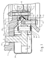
- Figure 1 shows an embodiment of the plain bearing according to the invention installed in a wind turbine in sectional view.
- the machine house 1 is by means of connecting screws 3 and Nuts 4 screwed to an inner ring 5.
- the inner ring 5 consists of a first ring part 6 and a second ring part 7, which are side by side in the axial direction are arranged and also by the connecting screws 3 and nuts 4th be held together.
- the connecting screws 3 are through corresponding through holes 8 and 9 in the ring parts 6 and 7 out.
- the through bores 9 in the second ring part 7 each have one larger diameter than the through holes 8 in the first ring part 6.
- each inserted bushings 10 which on a axial end have a circumferential collar 11 which is axially on the second Ring part 7 abuts.
- the other axial end of the socket 10 is supported axially on the first ring part 6, so that depending on the length of the bushings 10 an axial Gap 12 formed between the first ring part 6 and the second ring part 7 becomes.
- An outer ring 13 is fastened to the tower 2 by means of screws 14.
- the outer ring 13 has a circumferential radial projection 15 which is directed radially inwards is.
- the radial projection 15 has a perpendicular to the axial direction of the plain bearing oriented axial surface 16, one perpendicular to the radial direction of the plain bearing oriented radial surface 17 and a truncated cone surface 18, the central axis runs parallel to the axial direction of the plain bearing. All areas run rotationally symmetrical about the axis of the plain bearing.
- the radial projection 15 engages in an annular space 19 formed between the ring parts 6 and 7, which of the surfaces 16, 17 and 18 opposite and complementary to it trained areas 20, 21 and 22 is limited.
- Areas 20 and 22 are each set back a little so that recesses to accommodate Sliding segments 23 and 24 arise.
- the sliding segments 23 and 24 can For example, be glued to the surfaces 20 and 22 and are sliding Contact with the axial surface 16 and the truncated cone surface 18 Sliding pairing consisting of the sliding segments 23 and the axial surface 16 in essentially the weight of the nacelle 1 and the sliding pairing consisting of the sliding segments 24 and the truncated cone surface 18 ensures that Machine house 1 against tipping.
- the game in the two pairings depends depends on how strong the first ring part 6 and the second ring part 7 of the inner ring 5 with the help of the screws 3 are approximated. Because of this approximation the bushings 10 is limited, the game over the length of the bushings 10th be specified or set.
- the Outer ring 13 provided with a rack toothing.
- the Outer ring 13 has a U-shaped cross section, the U being radially outward is open.
- the two legs 27 and 28 are coaxial Provide through holes, into each of which a rack pin 29 is inserted is.
- the headstock bolts 29 are axially on both sides by a Seeger ring 30 secured, which engages in a groove 31 of the rack pin 29.
- the lower Seeger rings 30 can also be omitted if necessary, since the Triebstockbolzen 29 are already secured by their weight. In the Triebstockbolzen 29 engages a pinion 32 which is driven via a shaft 33 becomes.
- a plurality of pinions 32 can also be arranged distributed over the circumference his.
- the area of the drive rack and the pinion 32 or the pinion 32 is from a cover 34 which is attached to the nacelle 1 and each up to a small gap to the outer ring 13.
- an opening 35 is provided in the cover 34, through which the pinion 32 each engage in the rack teeth can.
- the cover 34 is used in the area of the rack teeth withheld lubricant and thus a loss of lubricant and prevent contamination of the surrounding machine parts.
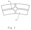
- FIG. 2 shows a plan view of a sliding segment 23.
- the sliding segments 24 are constructed accordingly and have only a slightly different shape.
- the Sliding segment 23 can consist of a plastic material and with or without Lubricant can be used. About the distribution of the lubricant and its The sliding segment 23 has to promote landfill in the area of the sliding surfaces Wells 36 on.
- the attachment of the sliding segment 23 can be done by gluing and / or screwing.
- the sliding segment 23 is on its Roughened back accordingly or has the sliding segment 23 corresponding Holes on.
- one could in principle also continuous sliding surface can be used.
- the handling is usually individual sliding segments 23, however, easier than that of a continuous one Sliding coating. This also applies with regard to the sliding segments 24.
- FIG 3 shows a detail of a second embodiment of the plain bearing according to the invention in a sectional view.
- the second Embodiment differs from that shown in Figure 1 regarding the components for the game setting.
- the section shown is therefore limited to the area in which these components are arranged.
- the two ring parts 6 and 7 of the inner ring are in turn by the Connection screws 3 and the nuts 4 screwed together. It is in second ring part 7, the connecting screw 3 through a threaded bushing 37 guided, which has an external thread 38, and in a threaded bore 39 in second ring part is screwed.
- the threaded bush 37 is through a Lock nut 40 secured against twisting.
- On the lock nut 40 is one Washer 41 is arranged, on which the connecting screw 3 rests axially.
- a game setting is by loosening the lock nut 40 and turning the threaded bush 37 possible.
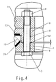
- FIG. 4 shows a detail of a third exemplary embodiment of the plain bearing according to the invention in a sectional view. It was the same Cutout selected, as in Figure 3.
- the peculiarity of the third Embodiment is that the game setting using Spacers 42 are used to establish the axial distance between the two Ring parts 6 and 7 of the inner ring 5 is set.
- the spacers 42 are arranged axially between the two ring parts 6 and 7 of the inner ring 5 and each take one of the connecting screws 3, with the help of which the two Ring parts 6 and 7 are screwed together.
- the third Exemplary embodiment no bushes 10 or threaded bushes 37 are provided, are the through bores 8 in the first ring part 6 and 9 in the second ring part 7 of the inner ring 5 each smooth and of the same diameter. To do that To change the play of the plain bearing, only the spacers 42 exchanged, the game by inserting thicker spacers 42 is increased and the game by inserting thinner spacers 42 is reduced.
Abstract
Description
Die Erfindung betrifft ein Gleitlager zur axialen und radialen Lagerung zweier relativ zueinander drehbarer Objekte.The invention relates to a slide bearing for the axial and radial mounting of two objects rotatable relative to each other.
Ein derartiges Gleitlager ist aus der DE 100 12 773 A1 bekannt. Das bekannte Gleitlager weist axial wirkende und radial wirkende Gleitflächen auf, die senkrecht zur Axialrichtung bzw. senkrecht zur Radialrichtung orientiert sind. Die axial wirkenden Gleitflächen können mittels hydraulischer Kolben mehr oder weniger stark gegen ihre Gegenflächen gepresst werden.Such a plain bearing is known from DE 100 12 773 A1. The known Slide bearing has axially acting and radially acting sliding surfaces that are vertical are oriented to the axial direction or perpendicular to the radial direction. The axial acting sliding surfaces can be more or less by means of hydraulic pistons are strongly pressed against their counter surfaces.
Insbesondere bedingt durch die hydraulische Verstellung der Gleitflächen ist die bekannte Lageranordnung relativ aufwändig aufgebaut. Weiterhin ist bei der bekannten Lageranordnung die Justierung sämtlicher Gleitflächen, d. h. einschließlich der radial wirkenden Gleitfläche, relativ schwierig.This is due in particular to the hydraulic adjustment of the sliding surfaces known bearing arrangement constructed relatively complex. Furthermore, the known bearing arrangement, the adjustment of all sliding surfaces, d. H. including the radially acting sliding surface, relatively difficult.
Der Erfindung liegt daher die Aufgabe zugrunde, ein radial und axial wirkendes Gleitlager anzugeben, dessen Gleitflächen leicht justierbar sind und das mit möglichst geringem Aufwand realisierbar ist.The invention is therefore based on the object of acting radially and axially Specify plain bearings whose sliding surfaces are easily adjustable and with the least possible effort can be achieved.
Diese Aufgabe wird durch die Merkmalskombination des Anspruchs 1 gelöst. This object is achieved by the combination of features of claim 1.
Das erfindungsgemäße Gleitlager zur axialen und radialen Lagerung zweier relativ zueinander drehbarer Objekte weist einen ersten Lagerring auf, der mit dem ersten Objekt verbunden ist und einen zweiten Lagerring, der mit dem zweiten Objekt verbunden ist. Der erste Lagerring und der zweite Lagerring weisen je eine Axialfläche auf, die direkt oder über einen dazwischen angeordneten Gleitbelag in einem Gleitkontakt zueinander stehen. Weiterhin weisen der erste Lagerring und der zweite Lagerring je eine Kegelstumpffläche auf, die direkt oder über einen dazwischen angeordneten Gleitbelag in einem Gleitkontakt zueinander stehen. Diese Ausbildung der Gleitpaarungen hat den Vorteil, dass die Justierung keinen hohen Aufwand erfordert und dass hohe Axialkräfte sowie bis zu einem begrenzten Maß auch Radialkräfte aufgenommen werden können.The slide bearing according to the invention for the axial and radial mounting of two relatively Objects that can be rotated relative to one another have a first bearing ring that is connected to the first Object is connected and a second bearing ring that is connected to the second object connected is. The first bearing ring and the second bearing ring each have one Axial surface, which directly or via an intermediate sliding surface in are in sliding contact with each other. Furthermore, the first bearing ring and the second bearing ring has a truncated cone surface, either directly or via a interposed sliding surface are in sliding contact with each other. This formation of the sliding pairings has the advantage that there is no adjustment requires great effort and that high axial forces as well as up to a limited Radial forces can also be absorbed.
Vorzugsweise ist der erste Lagerring in Axialrichtung aus zwei Ringteilen zusammengesetzt und der zweite Lagerring einstückig ausgebildet. Dadurch wird die Montierbarkeit des Gleitlagers bei gleichzeitig relativ großer Freiheit bei der konstruktiven Umsetzung sichergestellt.The first bearing ring is preferably made of two ring parts in the axial direction assembled and the second bearing ring formed in one piece. This will the mountability of the plain bearing with relatively great freedom at the same time constructive implementation ensured.
Die beiden Ringteile des ersten Lagerrings können einen Ringraum ausbilden, in den ein umlaufender Radialvorsprung des zweiten Lagerrings hineinragen kann. Dabei können die Axialfläche und die Kegelstumpffläche des zweiten Lagerrings jeweils am Radialvorsprung angeordnet sein. Weiterhin kann die axiale Ausdehnung des Ringraumes einstellbar sein. Dies hat den Vorteil, dass ein Einstellen oder Nachstellen des Spiels des Gleitlagers möglich ist, ohne dass das Gleitlager dazu demontiert werden muss. Dies ist insbesondere bei großen Lagerausführungen äußerst vorteilhaft, da sich damit hohe Demontagekosten einsparen lassen.The two ring parts of the first bearing ring can form an annular space, in which a circumferential radial projection of the second bearing ring can protrude. The axial surface and the truncated cone surface of the second bearing ring can each be arranged on the radial projection. Furthermore, the axial Expansion of the annulus to be adjustable. This has the advantage that a Adjustment or readjustment of the play of the plain bearing is possible without this Plain bearings must be dismantled. This is especially true with large ones Bearing designs are extremely advantageous, as this entails high dismantling costs save money.
Die beiden Ringteile des ersten Lagerrings können durch in Axialrichtung verlaufende Verbindungsschrauben miteinander verbunden sein. Dabei kann eines der beiden Ringteile Buchsen zur Aufnahme der Verbindungsschrauben aufweisen. Die Buchsen können in axialen Durchgangsbohrungen in einem der beiden Ringteile angeordnet sein, wobei die Buchsen länger sind als die Durchgangsbohrungen, so dass die axiale Ausdehnung des Ringraums durch die Länge der Buchsen einstellbar ist. Dies hat den Vorteil, dass sich das Spiel des Gleitlagers sehr einfach einstellen lässt, in dem die Länge der Buchsen jeweils entsprechend angepasst wird. Alternativ dazu können die Buchsen auch jeweils ein Außengewinde aufweisen, das in eine Gewindebohrung in einem der beiden Ringteile des ersten Lagerrings eingreift, so dass die axiale Ausdehnung des Ringraums durch Verdrehen der Buchsen einstellbar ist. Auch diese Variante hat den Vorteil einer sehr einfachen Einstellung des Lagerspiels, wobei in diesem Fall die Buchsen abhängig vom gewünschten Spiel verdreht werden. In einer weiteren Variante können zwischen den beiden Ringteilen des ersten Lagerrings Distanzscheiben angeordnet sein. Diese Variante bietet wiederum den Vorteil einer einfachen Spieleinstellung, indem die Dicke der Distanzscheiben abhängig vom gewünschten Spiel gewählt wird.The two ring parts of the first bearing ring can by in the axial direction extending connecting screws must be connected to each other. One can of the two ring parts have bushings for receiving the connecting screws. The bushings can be in axial through holes in one of the two Ring parts may be arranged, the bushings being longer than that Through holes, so that the axial expansion of the annular space through the Length of the bushings is adjustable. This has the advantage that the game of the Plain bearing can be set very easily, in which the length of the bushings is adjusted accordingly. Alternatively, the sockets can also be one Have external thread that in a threaded hole in one of the two Ring parts of the first bearing ring engages so that the axial extension of the Annulus is adjustable by turning the bushings. This variant also has the advantage of a very simple adjustment of the bearing play, in which case the bushings are rotated depending on the desired game. In another Variant can between the two ring parts of the first bearing ring Spacers can be arranged. This variant in turn offers the advantage of a simple adjustment of the game by changing the thickness of the spacers depending on desired game is selected.
Die Gleitbeläge können jeweils mit dem ersten oder zweiten Lagerring verklebt sein. Dies ermöglicht eine sehr einfache und kostengünstige Montage der Gleitbeläge. Im bevorzugten Ausführungsbeispiel sind die Gleitbeläge in Vertiefungen in den beiden Ringteilen des ersten Lagerrings eingesetzt. Dies hat den Vorteil, dass bei der Montage die Positionierung der Gleitbeläge stark vereinfacht wird und gibt den Gleitbelägen des weiteren einen zusätzlichen Halt.The sliding pads can each be glued to the first or second bearing ring his. This enables a very simple and inexpensive assembly of the Sliding coatings. In the preferred embodiment, the sliding linings are in Depressions used in the two ring parts of the first bearing ring. this has the advantage that the positioning of the sliding pads is strong during assembly is simplified and gives the sliding pads an additional hold.
Weiterhin sind die Gleitbeläge im bevorzugten Ausführungsbeispiel jeweils segmentiert ausgeführt. Dies hat den Vorteil, dass die Herstellungskosten für die Gleitbeläge erheblich gesenkt werden können. Ein weiterer Vorteil besteht darin, dass das Handling segmentierter Gleitbeläge wesentlich einfacher ist verglichen mit einstückig ausgebildeten Gleitbelägen. Dadurch wird die Montage der Gleitbeläge vereinfacht. Je nach den speziellen Erfordernissen des Anwendungsfalls können die Gleitbeläge Vertiefungen zur Aufnahme von Schmiermittel aufweisen. Dadurch wird die Verteilung eines gegebenenfalls verwendeten Schmierstoffs und dessen Deponierung im Bereich der Gleitflächen erleichtert. Furthermore, the sliding linings are each in the preferred embodiment executed segmented. This has the advantage that the manufacturing costs for the Sliding pads can be significantly reduced. Another advantage is that the handling of segmented sliding pads is much easier compared to one-piece sliding linings. This will assemble the sliding pads simplified. Depending on the special requirements of the application, the Sliding pads have recesses to hold lubricant. Thereby the distribution of any lubricant used and its Landing in the area of the sliding surfaces is facilitated.
Das erfindungsgemäße Gleitlager kann insbesondere bei einer Windenergieanlage eingesetzt werden, bei der eine Demontage des Gleitlagers mit sehr hohen Kosten verbunden ist und somit eine Spieleinstellung im montierten Zustand wünschenswert ist. Dabei kann mit dem erfindungsgemäßen Gleitlager beispielsweise das Maschinenhaus der Windenergieanlage drehbar gelagert werden, wobei das Gewicht des Maschinenhauses durch Zusammenwirken der Axialflächen aufgenommen wird und das Maschinenhaus durch Zusammenwirkung der Kegelstumpfflächen gegen Kippen gesichert wird. Desweiteren kann das erfindungsgemäße Gleitlager auch zur schwenkbaren Lagerung jeweils eines Rotorblatts der Windenergieanlage eingesetzt werden.The plain bearing according to the invention can be used, in particular, in a wind turbine are used in which a dismantling of the plain bearing with very high costs is connected and thus a game setting in the assembled state is desirable. It can with the plain bearing according to the invention for example, the nacelle of the wind turbine can be rotatably supported, the weight of the nacelle by the interaction of the axial surfaces is recorded and the machine house through the cooperation of Truncated cone surfaces is secured against tipping. Furthermore, it can Slide bearing according to the invention also for pivotable mounting one each Rotor blade of the wind turbine are used.
Die Erfindung wird nachstehend anhand der in der Zeichnung dargestellten Ausführungsbeispiele erläutert.The invention is described below with reference to the drawing Exemplary embodiments explained.
Es zeigen:
- Figur 1
- ein Ausführungsbeispiel des erfindungsgemäßen Gleitlagers, das in einer Windenergieanlage montiert ist, in Schnittdarstellung,
- Figur 2
- ein Gleitsegment in Aufsicht,
Figur 3- eine ausschnittsweise Abbildung eines zweiten Ausführungsbeispiels des erfindungsgemäßen Gleitlagers in Schnittdarstellung und
Figur 4- eine ausschnittsweise Abbildung eines dritten Ausführungsbeispiels des erfindungsgemäßen Gleitlagers in Schnittdarstellung.
- Figure 1
- 1 shows an exemplary embodiment of the slide bearing according to the invention, which is mounted in a wind energy installation, in a sectional view,
- Figure 2
- a sliding segment under supervision,
- Figure 3
- a partial illustration of a second embodiment of the plain bearing according to the invention in a sectional view and
- Figure 4
- a partial illustration of a third embodiment of the plain bearing according to the invention in a sectional view.
Figur 1 zeigt ein Ausführungsbeispiel des erfindungsgemäßen Gleitlagers eingebaut
in eine Windenergieanlage in Schnittdarstellung. Bei dieser Anwendung wird ein
Maschinenhaus 1 mit Hilfe des erfindungsgemäßen Gleitlagers auf einem Turm 2
drehbar abgestützt. Das Maschinenhaus 1 ist mittels Verbindungsschrauben 3 und
Muttern 4 an einem Innenring 5 angeschraubt. Der Innenring 5 besteht aus einem
ersten Ringteil 6 und einem zweiten Ringteil 7, die in Axialrichtung nebeneinander
angeordnet sind und ebenfalls durch die Verbindungsschrauben 3 und Muttern 4
zusammengehalten werden. Hierzu sind die Verbindungsschrauben 3 durch
entsprechende Durchgangsbohrungen 8 und 9 in den Ringteilen 6 und 7 geführt.
Dabei weisen die Durchgangsbohrungen 9 im zweiten Ringteil 7 jeweils einen
größeren Durchmesser als die Durchgangsbohrungen 8 im ersten Ringteil 6 aus. In
die Durchgangsbohrungen 9 sind jeweils Buchsen 10 eingeführt, die an einem
axialen Ende einen umlaufenden Kragen 11 aufweisen, der axial am zweiten
Ringteil 7 anliegt. Das andere axiale Ende der Buchse 10 stützt sich jeweils axial
am ersten Ringteil 6 ab, so dass abhängig von der Länge der Buchsen 10 ein axialer
Spalt 12 zwischen dem ersten Ringteil 6 und dem zweiten Ringteil 7 ausgebildet
wird.Figure 1 shows an embodiment of the plain bearing according to the invention installed
in a wind turbine in sectional view. In this application, a
Machine house 1 using the slide bearing according to the invention on a tower 2
rotatably supported. The machine house 1 is by means of connecting
Ein Außenring 13 ist über Schrauben 14 am Turm 2 befestigt. Der Außenring 13
weist einen umlaufenden Radialvorsprung 15 auf, der radial nach innen gerichtet
ist. Der Radialvorsprung 15 weist eine senkrecht zur Axialrichtung des Gleitlagers
orientierte Axialfläche 16, eine senkrecht zur Radialrichtung des Gleitlagers
orientierte Radialfläche 17 und eine Kegelstumpffläche 18 auf, deren Mittelachse
parallel zur Axialrichtung des Gleitlagers verläuft. Sämtliche Flächen verlaufen
rotationssymmetrisch um die Achse des Gleitlagers. Der Radialvorsprung 15 greift
in einen zwischen den Ringteilen 6 und 7 ausgebildeten Ringraum 19 ein, der von
den Flächen 16, 17 und 18 gegenüberliegenden und komplementär dazu
ausgebildeten Flächen 20, 21 und 22 begrenzt wird. Die Flächen 20 und 22 sind
jeweils etwas zurückversetzt, so dass Vertiefungen zur Aufnahme von
Gleitsegmenten 23 und 24 entstehen. Die Gleitsegmente 23 und 24 können
beispielsweise auf die Flächen 20 und 22 aufgeklebt sein und stehen im gleitenden
Kontakt zu der Axialfläche 16 und der Kegelstumpffläche 18. Dabei nimmt die
Gleitpaarung bestehend aus den Gleitsegmenten 23 und der Axialfläche 16 im
wesentlichen das Gewicht des Maschinenhauses 1 auf und die Gleitpaarung
bestehend aus den Gleitsegmenten 24 und der Kegelstumpffläche 18 sichert das
Maschinenhaus 1 gegen Kippen. Das Spiel in den beiden Gleitpaarungen hängt
davon ab, wie stark das erste Ringteil 6 und das zweite Ringteil 7 des Innenrings 5
mit Hilfe der Schrauben 3 einander angenähert sind. Da diese Annäherung durch
die Buchsen 10 begrenzt wird, kann das Spiel über die Länge der Buchsen 10
vorgegeben bzw. eingestellt werden.An
Um einen Austritt von gegebenenfalls im Bereich der Gleitsegmente 23 und 24
eingebrachten Schmierstoff zu verhindern, ist zwischen dem ersten Ringteil 6 und
dem Außenring 13 eine erste Dichtung 25 angeordnet und zwischen dem zweiten
Ringteil 7 und dem Außenring 13 eine zweite Dichtung 26.In order for an exit of possibly in the area of the sliding
Damit das Maschinenhaus 1 relativ zum Turm 2 geschwenkt werden kann, ist der
Außenring 13 mit einer Triebstockverzahnung versehen. Hierzu weist der
Außenring 13 einen U-förmigen Querschnitt auf, wobei das U radial nach außen
geöffnet ist. Die beiden Schenkel 27 und 28 sind mit koaxialen
Durchgangsbohrungen versehen, in die jeweils ein Triebstockbolzen 29 eingeführt
ist. Die Triebstockbolzen 29 sind beidseitig axial durch je einen Seeger-Ring 30
gesichert, der in eine Nut 31 des Triebstockbolzens 29 eingreift. Die unteren
Seeger-Ringe 30 können dabei gegebenenfalls auch entfallen, da die
Triebstockbolzen 29 bereits durch ihr Gewicht gesichert sind. In die
Triebstockbolzen 29 greift ein Ritzel 32 ein, das über eine Welle 33 angetrieben
wird. Dabei können auch mehrere Ritzel 32 über den Umfang verteilt angeordnet
sein. Der Bereich des Triebstocks und des Ritzels 32 bzw. der Ritzel 32 ist von
einer Abdeckung 34 umschlossen, die am Maschinenhaus 1 befestigt ist und jeweils
bis auf einen kleinen Spalt an den Außenring 13 heranreicht. Im Bereich des Ritzels
32 bzw. der Ritzel 32 ist in der Abdeckung 34 jeweils eine Öffnung 35 vorgesehen,
durch die hindurch das Ritzel 32 jeweils in die Triebstockverzahnung eingreifen
kann. Die Abdeckung 34 dient dazu, den im Bereich der Triebstockverzahnung
vorgehaltenen Schmierstoff zurückzuhalten und so einem Schmierstoffverlust und
einer Verschmutzung der umgebenden Maschinenteile vorzubeugen.So that the machine house 1 can be pivoted relative to the tower 2, the
Figur 2 zeigt eine Aufsicht auf ein Gleitsegment 23. Die Gleitsegmente 24 sind
entsprechend aufgebaut und besitzen nur eine geringfügig andere Form. Das
Gleitsegment 23 kann aus einem Kunststoffmaterial bestehen und mit oder ohne
Schmierstoff eingesetzt werden. Um die Verteilung des Schmierstoffs und dessen
Deponierung im Bereich der Gleitflächen zu fördern, weist das Gleitsegment 23
Vertiefungen 36 auf. Die Befestigung des Gleitsegments 23 kann durch Kleben
und/oder Verschrauben erfolgen. Hierzu ist das Gleitsegment 23 auf seiner
Rückseite entsprechend aufgerauht bzw. weist das Gleitsegment 23 entsprechende
Bohrungen auf. Statt des abgebildeten Gleitsegments 23 könnte auch prinzipiell ein
durchgehender Gleitbelag verwendet werden. In der Regel ist das Handling
einzelner Gleitsegmente 23 jedoch einfacher als das eines durchgehenden
Gleitbelags. Dies gilt auch im Hinblick auf die Gleitsegmente 24.FIG. 2 shows a plan view of a sliding
Figur 3 zeigt eine ausschnittsweise Abbildung eines zweiten Ausführungsbeispiels
des erfindungsgemäßen Gleitlagers in Schnittdarstellung. Das zweite
Ausführungsbeispiel unterscheidet sich von dem in Figur 1 dargestellten
hinsichtlich der Komponenten für die Spieleinstellung. Der dargestellte Ausschnitt
beschränkt sich daher auf den Bereich, in dem diese Komponente angeordnet sind.
Die beiden Ringteile 6 und 7 des Innenrings sind wiederum durch die
Verbindungsschrauben 3 und den Muttern 4 miteinander verschraubt. Dabei ist im
zweiten Ringteil 7 die Verbindungsschraube 3 durch eine Gewindebuchse 37
geführt, die ein Außengewinde 38 aufweist, und in eine Gewindebohrung 39 im
zweiten Ringteil eingeschraubt ist. Die Gewindebuchse 37 ist durch eine
Kontermutter 40 gegen Verdrehen gesichert. Auf der Kontermutter 40 ist eine
Unterlegscheibe 41 angeordnet, an der die Verbindungsschraube 3 axial anliegt.
Beim zweiten Ausführungsbeispiel ist eine Spieleinstellung jeweils durch Lösen
der Kontermutter 40 und Verdrehen der Gewindebuchse 37 möglich. Figure 3 shows a detail of a second embodiment
of the plain bearing according to the invention in a sectional view. The second
Embodiment differs from that shown in Figure 1
regarding the components for the game setting. The section shown
is therefore limited to the area in which these components are arranged.
The two
Figur 4 zeigt eine ausschnittsweise Abbildung eines dritten Ausführungsbeispiels
des erfindungsgemäßen Gleitlagers in Schnittdarstellung. Es wurde der gleiche
Ausschnitt gewählt, wie in Figur 3. Die Besonderheit beim dritten
Ausführungsbeispiel besteht darin, dass die Spieleinstellung mit Hilfe von
Distanzscheiben 42 erfolgt, mit denen der axiale Abstand zwischen den beiden
Ringteilen 6 und 7 des Innenrings 5 eingestellt wird. Die Distanzscheiben 42 sind
axial zwischen den beiden Ringteilen 6 und 7 des Innenrings 5 angeordnet und
nehmen jeweils eine der Verbindungsschrauben 3 auf, mit deren Hilfe die beiden
Ringteile 6 und 7 miteinander verschraubt sind. Da beim dritten
Ausführungsbeispiel keine Buchsen 10 bzw. Gewindebuchsen 37 vorgesehen sind,
sind die Durchgangsbohrungen 8 im ersten Ringteil 6 und 9 im zweiten Ringteil 7
des Innenrings 5 jeweils glatt und mit gleichem Durchmesser ausgeführt. Um das
Spiel des Gleitlagers zu verändern, werden lediglich die Distanzscheiben 42
ausgetauscht, wobei durch das Einsetzen dickerer Distanzscheiben 42 das Spiel
vergrößert wird und durch das Einsetzen dünnerer Distanzscheiben 42 das Spiel
verkleinert wird.FIG. 4 shows a detail of a third exemplary embodiment
of the plain bearing according to the invention in a sectional view. It was the same
Cutout selected, as in Figure 3. The peculiarity of the third
Embodiment is that the game
Alternativ zur dargestellten Lagerung des Maschinenhauses 1 kann das erfindungsgemäße Gleitlager auch zur Lagerung der einzelnen Rotorblätter der Windenergieanlage eingesetzt werden und ein Schwenken der Rotorblätter um deren Längsachse ermöglichen. Diese Schwenkbewegung ist erforderlich, um den Anstellwinkel der einzelnen Rotorblätter an die jeweiligen Windverhältnisse anzupassen. As an alternative to the illustrated storage of the machine house 1, this can Slide bearing according to the invention also for storing the individual rotor blades of the Wind energy plant are used and swiveling the rotor blades around allow their longitudinal axis. This pivotal movement is required to Angle of attack of the individual rotor blades to the respective wind conditions adapt.
- 11
- Maschinenhauspower house
- 22
- Turmtower
- 33
- Verbindungsschraubeconnecting screw
- 44
- Muttermother
- 55
- Innenringinner ring
- 66
- erstes Ringteil (Innenring 5)first ring part (inner ring 5)
- 77
- zweites Ringteil (Innenring 5)second ring part (inner ring 5)
- 88th
- Durchgangsbohrung (erstes Ringteil 6)Through hole (first ring part 6)
- 99
- Durchgangsbohrung (zweites Ringteil 7)Through hole (second ring part 7)
- 1010
- BuchseRifle
- 1111
- Kragencollar
- 1212
- Spaltgap
- 1313
- Außenringouter ring
- 1414
- Schraubescrew
- 1515
- Radialvorsprung (Außenring 13)Radial projection (outer ring 13)
- 1616
- Axialfläche (Außenring 13)Axial surface (outer ring 13)
- 1717
- Radialfläche (Außenring 13)Radial surface (outer ring 13)
- 1818
- Kegelstumpffläche (Außenring 13)Truncated cone surface (outer ring 13)
- 1919
- Ringraumannulus
- 2020
- Axialfläche (erstes Ringteil 6)Axial surface (first ring part 6)
- 2121
- Radialfläche (erstes Ringteil 6)Radial surface (first ring part 6)
- 2222
- Kegelstumpffläche (zweites Ringteil 7)Truncated cone surface (second ring part 7)
- 2323
- Gleitsegment sliding segment
- 2424
- Gleitsegmentsliding segment
- 2525
- Dichtungpoetry
- 2626
- Dichtungpoetry
- 2727
- erster Schenkel (Außenring 13)first leg (outer ring 13)
- 2828
- zweiter Schenkel (Außenring 13)second leg (outer ring 13)
- 2929
- TriebstockbolzenLantern pin
- 3030
- Seeger-RingSeeger ring
- 3131
- Nut (Triebstockbolzen 29)Groove (rack pin 29)
- 3232
- Ritzelpinion
- 3333
- Wellewave
- 3434
- Abdeckungcover
- 3535
- Öffnungopening
- 3636
- Vertiefung (Gleitbelag 23)Deepening (sliding surface 23)
- 3737
- Gewindebuchsethreaded bushing
- 3838
- Außengewinde (Gewindebuchse 37)Male thread (threaded bush 37)
- 3939
- Gewindebohrung (zweites Ringteil 7)Tapped hole (second ring part 7)
- 4040
- Kontermutterlocknut
- 4141
- Unterlegscheibewasher
- 4242
- Distanzscheibespacer
Claims (17)
Applications Claiming Priority (2)
| Application Number | Priority Date | Filing Date | Title |
|---|---|---|---|
| DE20208133U DE20208133U1 (en) | 2002-05-24 | 2002-05-24 | Plain bearings for axial and radial bearings |
| DE20208133U | 2002-05-24 |
Publications (3)
| Publication Number | Publication Date |
|---|---|
| EP1367273A2 true EP1367273A2 (en) | 2003-12-03 |
| EP1367273A3 EP1367273A3 (en) | 2006-04-19 |
| EP1367273B1 EP1367273B1 (en) | 2008-07-09 |
Family
ID=28799100
Family Applications (1)
| Application Number | Title | Priority Date | Filing Date |
|---|---|---|---|
| EP03011683A Expired - Lifetime EP1367273B1 (en) | 2002-05-24 | 2003-05-23 | Sliding bearing for radial and axial loads |
Country Status (3)
| Country | Link |
|---|---|
| EP (1) | EP1367273B1 (en) |
| AT (1) | ATE400745T1 (en) |
| DE (2) | DE20208133U1 (en) |
Cited By (6)
| Publication number | Priority date | Publication date | Assignee | Title |
|---|---|---|---|---|
| WO2008077983A1 (en) * | 2006-12-26 | 2008-07-03 | Gamesa Innovation & Technology, S.L. | Yaw ring with sliding base for wind generators |
| US8075190B1 (en) | 2010-09-16 | 2011-12-13 | Vestas Wind Systems A/S | Spherical plain bearing pocket arrangement and wind turbine having such a spherical plain bearing |
| US8172531B2 (en) | 2011-01-10 | 2012-05-08 | Vestas Wind Systems A/S | Plain bearing for a wind turbine blade and method of operating a wind turbine having such a plain bearing |
| CN102834611A (en) * | 2010-04-14 | 2012-12-19 | 米巴·格来特来格有限公司 | Bearing element |
| US8727728B2 (en) | 2010-09-16 | 2014-05-20 | Vestas Wind Systems A/S | Convertible bearing for a wind turbine and method for operating same |
| US8734105B2 (en) | 2010-09-16 | 2014-05-27 | Vestas Wind Systems A/S | Control system for a wind turbine and method of operating a wind turbine based on monitoring a bearing |
Families Citing this family (3)
| Publication number | Priority date | Publication date | Assignee | Title |
|---|---|---|---|---|
| DE102005051912A1 (en) * | 2005-10-29 | 2007-05-03 | Ab Skf | arrangement |
| DE102006013275B4 (en) * | 2006-03-21 | 2008-07-03 | Air Fertigung-Technologie Gmbh | Storage system for ring propellers |
| AU2008258839A1 (en) * | 2007-06-04 | 2008-12-11 | Suzlon Energy Gmbh | Bearing arrangement for a wind turbine |
Citations (7)
| Publication number | Priority date | Publication date | Assignee | Title |
|---|---|---|---|---|
| DE850365C (en) * | 1941-11-13 | 1952-09-25 | Leitz Ernst Gmbh | Impact and play-free storage of spindles for precision machining by means of two bearings, of which at least one can be adjusted and readjusted |
| US2719761A (en) * | 1952-10-28 | 1955-10-04 | Lapointe Machine Tool Co | Bearing structure for sliding machine carriage |
| DE2311864A1 (en) * | 1972-03-09 | 1973-09-13 | Skf Cie Applic Mecanique | END BEARING DEVICE WITH CONICAL FRICTION RING |
| DE10012773A1 (en) * | 1999-04-17 | 2001-08-09 | Holzmueller Juergen | Rotary joint, especially for machine housing bearing for wind power system, has brake integrated into rotary joint with brake element(s) mounted in one rotary joint part |
| DE19962978C1 (en) * | 1999-12-24 | 2001-08-30 | Aloys Wobben | Wind turbine with a tower-based machine head |
| DE10043936A1 (en) * | 2000-09-07 | 2002-04-04 | Skf Gmbh | Bearing for mast of wind turbine comprises outer ring with internal groove and inner ring with radial bores though which rods are inserted which have upper sections carrying anti-friction pads on faces which contact groove in outer ring |
| DE10112517C1 (en) * | 2001-03-09 | 2002-04-25 | Atecs Mannesmann Ag | Large diameter rotary bearing e.g. for mobile crane, excavator or concrete mixer vehicle, has 3 sets of corresponding bearing surfaces between relatively rotating bearing parts |
Family Cites Families (6)
| Publication number | Priority date | Publication date | Assignee | Title |
|---|---|---|---|---|
| US3434762A (en) * | 1963-07-11 | 1969-03-25 | Garrett Corp | Hydrodynamic shaft bearing |
| FR1424679A (en) * | 1965-02-12 | 1966-01-14 | Licentia Gmbh | Mixed bearing forming slider and guide bearing for electric machines with vertical shaft |
| US3418027A (en) * | 1966-07-15 | 1968-12-24 | Atomic Energy Commission Usa | Rotary table |
| DE2827880B1 (en) * | 1978-06-24 | 1980-01-10 | Heidenhain Gmbh Dr Johannes | Gas storage for fast rotating parts |
| JPS58174716A (en) * | 1982-04-07 | 1983-10-13 | Mitsubishi Electric Corp | Bearing device of rotary electrical equipment |
| US5286116A (en) * | 1992-08-31 | 1994-02-15 | Newport News Shipbuilding And Dry Dock Company | Bearing assembly |
-
2002
- 2002-05-24 DE DE20208133U patent/DE20208133U1/en not_active Expired - Lifetime
-
2003
- 2003-05-23 DE DE50310097T patent/DE50310097D1/en not_active Expired - Fee Related
- 2003-05-23 AT AT03011683T patent/ATE400745T1/en not_active IP Right Cessation
- 2003-05-23 EP EP03011683A patent/EP1367273B1/en not_active Expired - Lifetime
Patent Citations (7)
| Publication number | Priority date | Publication date | Assignee | Title |
|---|---|---|---|---|
| DE850365C (en) * | 1941-11-13 | 1952-09-25 | Leitz Ernst Gmbh | Impact and play-free storage of spindles for precision machining by means of two bearings, of which at least one can be adjusted and readjusted |
| US2719761A (en) * | 1952-10-28 | 1955-10-04 | Lapointe Machine Tool Co | Bearing structure for sliding machine carriage |
| DE2311864A1 (en) * | 1972-03-09 | 1973-09-13 | Skf Cie Applic Mecanique | END BEARING DEVICE WITH CONICAL FRICTION RING |
| DE10012773A1 (en) * | 1999-04-17 | 2001-08-09 | Holzmueller Juergen | Rotary joint, especially for machine housing bearing for wind power system, has brake integrated into rotary joint with brake element(s) mounted in one rotary joint part |
| DE19962978C1 (en) * | 1999-12-24 | 2001-08-30 | Aloys Wobben | Wind turbine with a tower-based machine head |
| DE10043936A1 (en) * | 2000-09-07 | 2002-04-04 | Skf Gmbh | Bearing for mast of wind turbine comprises outer ring with internal groove and inner ring with radial bores though which rods are inserted which have upper sections carrying anti-friction pads on faces which contact groove in outer ring |
| DE10112517C1 (en) * | 2001-03-09 | 2002-04-25 | Atecs Mannesmann Ag | Large diameter rotary bearing e.g. for mobile crane, excavator or concrete mixer vehicle, has 3 sets of corresponding bearing surfaces between relatively rotating bearing parts |
Cited By (9)
| Publication number | Priority date | Publication date | Assignee | Title |
|---|---|---|---|---|
| WO2008077983A1 (en) * | 2006-12-26 | 2008-07-03 | Gamesa Innovation & Technology, S.L. | Yaw ring with sliding base for wind generators |
| ES2326852A1 (en) * | 2006-12-26 | 2009-10-20 | GAMESA INNOVATION & TECHNOLOGY, S.L. | Yaw ring with sliding base for wind generators |
| CN102834611A (en) * | 2010-04-14 | 2012-12-19 | 米巴·格来特来格有限公司 | Bearing element |
| CN102834611B (en) * | 2010-04-14 | 2015-11-25 | 米巴·格来特来格有限公司 | Supporting element |
| US8075190B1 (en) | 2010-09-16 | 2011-12-13 | Vestas Wind Systems A/S | Spherical plain bearing pocket arrangement and wind turbine having such a spherical plain bearing |
| US8079761B1 (en) | 2010-09-16 | 2011-12-20 | Vestas Wind Systems A/S | Cylindrical plain bearing pocket arrangement and wind turbine having such a cylindrical plain bearing |
| US8727728B2 (en) | 2010-09-16 | 2014-05-20 | Vestas Wind Systems A/S | Convertible bearing for a wind turbine and method for operating same |
| US8734105B2 (en) | 2010-09-16 | 2014-05-27 | Vestas Wind Systems A/S | Control system for a wind turbine and method of operating a wind turbine based on monitoring a bearing |
| US8172531B2 (en) | 2011-01-10 | 2012-05-08 | Vestas Wind Systems A/S | Plain bearing for a wind turbine blade and method of operating a wind turbine having such a plain bearing |
Also Published As
| Publication number | Publication date |
|---|---|
| ATE400745T1 (en) | 2008-07-15 |
| DE50310097D1 (en) | 2008-08-21 |
| EP1367273A3 (en) | 2006-04-19 |
| DE20208133U1 (en) | 2003-10-02 |
| EP1367273B1 (en) | 2008-07-09 |
Similar Documents
| Publication | Publication Date | Title |
|---|---|---|
| EP1975405B1 (en) | Connection of elements of a wind turbine plant, use thereof and method | |
| EP2812568B1 (en) | Roller bearing arrangement for mounting parts of a wind power plant and a wind power plant having a blade bearing designed in such a manner | |
| EP2676042B1 (en) | Axial-radial rolling contact bearing, in particular for supporting rotor blades on a wind turbine | |
| EP1426639B1 (en) | Method for mounting a two row tapered roller bearing with segmented bearing rings in a wind motor | |
| WO2001048376A2 (en) | Plain bearing and wind energy unit with said bearing | |
| EP2154367B1 (en) | Method of assembling a rotor hub on a rotor shaft for a wind energy system and wind energy system | |
| EP3550140B1 (en) | Machine support for wind turbine | |
| EP1668263B1 (en) | Pivot bearing arrangement of a rotational body | |
| WO2018189143A1 (en) | Bearing arrangement for mounting a rotor blade of a wind turbine | |
| WO2010037372A1 (en) | Rotational connection, in particular a multi-row angular contact bearing having three concentric bearing rings, for a wind turbine and wind turbine comprising said rotational connection | |
| EP1365147A2 (en) | Slide bearings for wind turbines | |
| EP1426644B1 (en) | Assembled brake disc for a vehicle disc brake | |
| EP1367273B1 (en) | Sliding bearing for radial and axial loads | |
| DE10043936A1 (en) | Bearing for mast of wind turbine comprises outer ring with internal groove and inner ring with radial bores though which rods are inserted which have upper sections carrying anti-friction pads on faces which contact groove in outer ring | |
| EP3657012B1 (en) | Centring pin for the creation of a flange joint between two components of a wind power plant, method for producing a flange connection and flange connection | |
| EP3794228A1 (en) | Rotary connection for a rotor blade of a wind turbine | |
| EP3384183B1 (en) | Planetary carrier for a transmission stage of a planetary transmission, and pre-tensioning method | |
| EP4062078B1 (en) | Bearing arrangement and method for producing said type of bearing arrangment | |
| DE10033894A1 (en) | Disassembly device for a self-adjusting bearing | |
| DE102006018264B4 (en) | bearing arrangement | |
| EP1367274A2 (en) | Sliding bearing with integrated gearing | |
| DE10316005A1 (en) | Procedure for adjusting the clearance or preload of a bearing | |
| WO2019122023A1 (en) | Wind turbine, rotor system, and method for using a wind turbine | |
| DE102004029581A1 (en) | Central joint for a wishbone of motor vehicles | |
| EP1365148A2 (en) | Lubricating system for the azimuth turning gear of the nacelle of a wind turbine |
Legal Events
| Date | Code | Title | Description |
|---|---|---|---|
| PUAI | Public reference made under article 153(3) epc to a published international application that has entered the european phase |
Free format text: ORIGINAL CODE: 0009012 |
|
| AK | Designated contracting states |
Kind code of ref document: A2 Designated state(s): AT BE BG CH CY CZ DE DK EE ES FI FR GB GR HU IE IT LI LU MC NL PT RO SE SI SK TR |
|
| AX | Request for extension of the european patent |
Extension state: AL LT LV MK |
|
| PUAL | Search report despatched |
Free format text: ORIGINAL CODE: 0009013 |
|
| AK | Designated contracting states |
Kind code of ref document: A3 Designated state(s): AT BE BG CH CY CZ DE DK EE ES FI FR GB GR HU IE IT LI LU MC NL PT RO SE SI SK TR |
|
| AX | Request for extension of the european patent |
Extension state: AL LT LV MK |
|
| 17P | Request for examination filed |
Effective date: 20060511 |
|
| AKX | Designation fees paid |
Designated state(s): AT BE BG CH CY CZ DE DK EE ES FI FR GB GR HU IE IT LI LU MC NL PT RO SE SI SK TR |
|
| GRAP | Despatch of communication of intention to grant a patent |
Free format text: ORIGINAL CODE: EPIDOSNIGR1 |
|
| GRAS | Grant fee paid |
Free format text: ORIGINAL CODE: EPIDOSNIGR3 |
|
| GRAA | (expected) grant |
Free format text: ORIGINAL CODE: 0009210 |
|
| AK | Designated contracting states |
Kind code of ref document: B1 Designated state(s): AT BE BG CH CY CZ DE DK EE ES FI FR GB GR HU IE IT LI LU MC NL PT RO SE SI SK TR |
|
| REG | Reference to a national code |
Ref country code: GB Ref legal event code: FG4D Free format text: NOT ENGLISH |
|
| REG | Reference to a national code |
Ref country code: CH Ref legal event code: EP |
|
| REF | Corresponds to: |
Ref document number: 50310097 Country of ref document: DE Date of ref document: 20080821 Kind code of ref document: P |
|
| REG | Reference to a national code |
Ref country code: IE Ref legal event code: FG4D Free format text: LANGUAGE OF EP DOCUMENT: GERMAN |
|
| NLV1 | Nl: lapsed or annulled due to failure to fulfill the requirements of art. 29p and 29m of the patents act | ||
| PG25 | Lapsed in a contracting state [announced via postgrant information from national office to epo] |
Ref country code: NL Free format text: LAPSE BECAUSE OF FAILURE TO SUBMIT A TRANSLATION OF THE DESCRIPTION OR TO PAY THE FEE WITHIN THE PRESCRIBED TIME-LIMIT Effective date: 20080709 Ref country code: PT Free format text: LAPSE BECAUSE OF FAILURE TO SUBMIT A TRANSLATION OF THE DESCRIPTION OR TO PAY THE FEE WITHIN THE PRESCRIBED TIME-LIMIT Effective date: 20081209 Ref country code: ES Free format text: LAPSE BECAUSE OF FAILURE TO SUBMIT A TRANSLATION OF THE DESCRIPTION OR TO PAY THE FEE WITHIN THE PRESCRIBED TIME-LIMIT Effective date: 20081020 |
|
| PG25 | Lapsed in a contracting state [announced via postgrant information from national office to epo] |
Ref country code: SI Free format text: LAPSE BECAUSE OF FAILURE TO SUBMIT A TRANSLATION OF THE DESCRIPTION OR TO PAY THE FEE WITHIN THE PRESCRIBED TIME-LIMIT Effective date: 20080709 Ref country code: BG Free format text: LAPSE BECAUSE OF FAILURE TO SUBMIT A TRANSLATION OF THE DESCRIPTION OR TO PAY THE FEE WITHIN THE PRESCRIBED TIME-LIMIT Effective date: 20081009 Ref country code: FI Free format text: LAPSE BECAUSE OF FAILURE TO SUBMIT A TRANSLATION OF THE DESCRIPTION OR TO PAY THE FEE WITHIN THE PRESCRIBED TIME-LIMIT Effective date: 20080709 |
|
| REG | Reference to a national code |
Ref country code: IE Ref legal event code: FD4D |
|
| PG25 | Lapsed in a contracting state [announced via postgrant information from national office to epo] |
Ref country code: DK Free format text: LAPSE BECAUSE OF FAILURE TO SUBMIT A TRANSLATION OF THE DESCRIPTION OR TO PAY THE FEE WITHIN THE PRESCRIBED TIME-LIMIT Effective date: 20080709 Ref country code: IE Free format text: LAPSE BECAUSE OF FAILURE TO SUBMIT A TRANSLATION OF THE DESCRIPTION OR TO PAY THE FEE WITHIN THE PRESCRIBED TIME-LIMIT Effective date: 20080709 Ref country code: EE Free format text: LAPSE BECAUSE OF FAILURE TO SUBMIT A TRANSLATION OF THE DESCRIPTION OR TO PAY THE FEE WITHIN THE PRESCRIBED TIME-LIMIT Effective date: 20080709 |
|
| PLBE | No opposition filed within time limit |
Free format text: ORIGINAL CODE: 0009261 |
|
| STAA | Information on the status of an ep patent application or granted ep patent |
Free format text: STATUS: NO OPPOSITION FILED WITHIN TIME LIMIT |
|
| PG25 | Lapsed in a contracting state [announced via postgrant information from national office to epo] |
Ref country code: RO Free format text: LAPSE BECAUSE OF FAILURE TO SUBMIT A TRANSLATION OF THE DESCRIPTION OR TO PAY THE FEE WITHIN THE PRESCRIBED TIME-LIMIT Effective date: 20080709 Ref country code: CZ Free format text: LAPSE BECAUSE OF FAILURE TO SUBMIT A TRANSLATION OF THE DESCRIPTION OR TO PAY THE FEE WITHIN THE PRESCRIBED TIME-LIMIT Effective date: 20080709 Ref country code: SK Free format text: LAPSE BECAUSE OF FAILURE TO SUBMIT A TRANSLATION OF THE DESCRIPTION OR TO PAY THE FEE WITHIN THE PRESCRIBED TIME-LIMIT Effective date: 20080709 |
|
| 26N | No opposition filed |
Effective date: 20090414 |
|
| PG25 | Lapsed in a contracting state [announced via postgrant information from national office to epo] |
Ref country code: IT Free format text: LAPSE BECAUSE OF FAILURE TO SUBMIT A TRANSLATION OF THE DESCRIPTION OR TO PAY THE FEE WITHIN THE PRESCRIBED TIME-LIMIT Effective date: 20080709 |
|
| PGFP | Annual fee paid to national office [announced via postgrant information from national office to epo] |
Ref country code: DE Payment date: 20090528 Year of fee payment: 7 |
|
| BERE | Be: lapsed |
Owner name: A.B. SKF Effective date: 20090531 |
|
| PG25 | Lapsed in a contracting state [announced via postgrant information from national office to epo] |
Ref country code: MC Free format text: LAPSE BECAUSE OF NON-PAYMENT OF DUE FEES Effective date: 20090531 |
|
| REG | Reference to a national code |
Ref country code: CH Ref legal event code: PL |
|
| GBPC | Gb: european patent ceased through non-payment of renewal fee |
Effective date: 20090523 |
|
| PG25 | Lapsed in a contracting state [announced via postgrant information from national office to epo] |
Ref country code: LI Free format text: LAPSE BECAUSE OF NON-PAYMENT OF DUE FEES Effective date: 20090531 Ref country code: CH Free format text: LAPSE BECAUSE OF NON-PAYMENT OF DUE FEES Effective date: 20090531 Ref country code: SE Free format text: LAPSE BECAUSE OF FAILURE TO SUBMIT A TRANSLATION OF THE DESCRIPTION OR TO PAY THE FEE WITHIN THE PRESCRIBED TIME-LIMIT Effective date: 20081009 |
|
| REG | Reference to a national code |
Ref country code: FR Ref legal event code: ST Effective date: 20100129 |
|
| PG25 | Lapsed in a contracting state [announced via postgrant information from national office to epo] |
Ref country code: FR Free format text: LAPSE BECAUSE OF NON-PAYMENT OF DUE FEES Effective date: 20090602 |
|
| PG25 | Lapsed in a contracting state [announced via postgrant information from national office to epo] |
Ref country code: GB Free format text: LAPSE BECAUSE OF NON-PAYMENT OF DUE FEES Effective date: 20090523 |
|
| PG25 | Lapsed in a contracting state [announced via postgrant information from national office to epo] |
Ref country code: BE Free format text: LAPSE BECAUSE OF NON-PAYMENT OF DUE FEES Effective date: 20090531 |
|
| PG25 | Lapsed in a contracting state [announced via postgrant information from national office to epo] |
Ref country code: AT Free format text: LAPSE BECAUSE OF NON-PAYMENT OF DUE FEES Effective date: 20090523 |
|
| PG25 | Lapsed in a contracting state [announced via postgrant information from national office to epo] |
Ref country code: GR Free format text: LAPSE BECAUSE OF FAILURE TO SUBMIT A TRANSLATION OF THE DESCRIPTION OR TO PAY THE FEE WITHIN THE PRESCRIBED TIME-LIMIT Effective date: 20081010 |
|
| PG25 | Lapsed in a contracting state [announced via postgrant information from national office to epo] |
Ref country code: LU Free format text: LAPSE BECAUSE OF NON-PAYMENT OF DUE FEES Effective date: 20090523 Ref country code: DE Free format text: LAPSE BECAUSE OF NON-PAYMENT OF DUE FEES Effective date: 20101201 |
|
| PG25 | Lapsed in a contracting state [announced via postgrant information from national office to epo] |
Ref country code: HU Free format text: LAPSE BECAUSE OF FAILURE TO SUBMIT A TRANSLATION OF THE DESCRIPTION OR TO PAY THE FEE WITHIN THE PRESCRIBED TIME-LIMIT Effective date: 20090110 |
|
| PG25 | Lapsed in a contracting state [announced via postgrant information from national office to epo] |
Ref country code: TR Free format text: LAPSE BECAUSE OF FAILURE TO SUBMIT A TRANSLATION OF THE DESCRIPTION OR TO PAY THE FEE WITHIN THE PRESCRIBED TIME-LIMIT Effective date: 20080709 |
|
| PG25 | Lapsed in a contracting state [announced via postgrant information from national office to epo] |
Ref country code: CY Free format text: LAPSE BECAUSE OF FAILURE TO SUBMIT A TRANSLATION OF THE DESCRIPTION OR TO PAY THE FEE WITHIN THE PRESCRIBED TIME-LIMIT Effective date: 20080709 |