EP1367173A2 - Dryer vacuum box - Google Patents
Dryer vacuum box Download PDFInfo
- Publication number
- EP1367173A2 EP1367173A2 EP03012372A EP03012372A EP1367173A2 EP 1367173 A2 EP1367173 A2 EP 1367173A2 EP 03012372 A EP03012372 A EP 03012372A EP 03012372 A EP03012372 A EP 03012372A EP 1367173 A2 EP1367173 A2 EP 1367173A2
- Authority
- EP
- European Patent Office
- Prior art keywords
- vacuum
- dryer
- vacuum box
- canvas
- roll
- Prior art date
- Legal status (The legal status is an assumption and is not a legal conclusion. Google has not performed a legal analysis and makes no representation as to the accuracy of the status listed.)
- Withdrawn
Links
Images


Classifications
-
- D—TEXTILES; PAPER
- D21—PAPER-MAKING; PRODUCTION OF CELLULOSE
- D21G—CALENDERS; ACCESSORIES FOR PAPER-MAKING MACHINES
- D21G9/00—Other accessories for paper-making machines
- D21G9/0063—Devices for threading a web tail through a paper-making machine
-
- D—TEXTILES; PAPER
- D21—PAPER-MAKING; PRODUCTION OF CELLULOSE
- D21F—PAPER-MAKING MACHINES; METHODS OF PRODUCING PAPER THEREON
- D21F5/00—Dryer section of machines for making continuous webs of paper
- D21F5/02—Drying on cylinders
- D21F5/04—Drying on cylinders on two or more drying cylinders
- D21F5/042—Drying on cylinders on two or more drying cylinders in combination with suction or blowing devices
Definitions
- This invention relates to a dryer vacuum box incorporated in a dryer part of a paper machine.
- a conventional paper machine employs a dryer part of, for example, (1) the single deck type wherein dryer rolls are juxtaposed in one stage or (2) the double deck type wherein dryer rolls are juxtaposed in two stages. Dryer parts of the types mentioned are described below.
- a plurality of dryer rolls are disposed in an upper stage while a plurality of vacuum rolls are disposed in a lower stage, and a belt-like canvas is wrapped alternately around the dryer rolls and the vacuum rolls.
- a paper web (wet-web) dehydrated by a press part on the upstream runs alternately between and around the dryer rolls and the vacuum rolls while it is supported at one face thereof by the canvas.
- the paper web is supported on the lower face side of the canvas, and on each of the dryer rolls, the paper web is pressed to the surface of the dryer roll by the canvas and dried by heat of the dryer roll.
- the paper web heated and dried by each of the dryer rolls advances to one of the vacuum rolls together with the canvas.
- the paper web is spaced away from the dryer roll, such sticking that the paper web sticks to the surface of the dryer roll sometimes occurs .
- the sticking is considered to be a phenomenon which occurs because paper powder sticking to the surface of the dryer roll acts as if it were paste to paste the paper web to the surface of the dryer roll. If such sticking occurs, then the paper web is taken by the dryer roll side and spaced away from the canvas. Consequently, running of the paper web is disordered, and in the worst case, break of the paper web occurs.
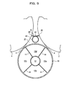
- the dryer part of a conventional paper machine includes such a vacuum box as shown in FIGS. 9 and 10 as a running stabilization apparatus for a paper web in order to suppress disordering of running of a paper web in a draw section from a dryer roll to a vacuum roll.
- FIG. 9 is a side elevational view partly in section showing a configuration of a conventional vacuum box
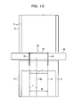
- FIG. 10 is a front elevational view of the vacuum box. Referring to FIGS. 9 and 10, two side seals 22 and 24 and two cross seals 26 and 28 are disposed among two adjacent dryer rolls 2 and 4 and a vacuum roll 10.
- the side seals 22 and 24 and the cross seals 26 and 28 are secured to and supported on a support pipe 40 disposed between the dryer rolls 2 and 4 and extending in a widthwise direction of the apparatus.
- the side seals 22 and 24 are shaped in conformity with the shape of a side section of a space defined by a portion of a canvas 6 from the dryer roll 2 to the vacuum roll 10, the vacuum roll 10 and another portion of the canvas 6 from the vacuum roll 10 to the dryer roll 4, and are disposed in a spaced relationship from each other by a distance substantially equal to the width W of a paper web 8 in the widthwise direction of the apparatus.
- the cross seals 26 and 28 are disposed in the widthwise direction of the apparatus between the side seals 22 and 24 and secured to a bracket 42 securely mounted at an upper end portion of the support pipe 40.
- One of the cross seals 26 and 28, that is, the cross seal 26, is secured to an end portion of the bracket 42 adjacent the dryer roll 2 and serves as a lid for a gap between the bracket 42 and the canvas 6 wrapped around the dryer roll 2.
- the other cross seal 28 is secured to an end portion of the bracket 42 adjacent the dryer roll 4 and serves as a lid for a gap between the bracket 42 and the canvas 6 wrapped around the dryer roll 4.
- An enclosed space 20 is defined by the side seals 22 and 24, cross seals 26 and 28, vacuum roll 10 and portions of the canvas 6, and the enclosed space 20 functions as a vacuum box 20 as a running stabilization apparatus for the paper web 8.
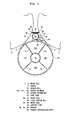
- the inside of the vacuum roll 10 is partitioned into a plurality of chambers 10a, 10b, 10c and 10d in a circumferential direction by partition plates 14 as shown in FIG. 9, and the chambers 10a, 10b and 10c of them along which the canvas 6 is wrapped serve as vacuum chambers which are acted upon by vacuum suction force from a vacuum introduction path 12 disposed at the center of the vacuum roll 10.
- a plurality of holes are perforated in a surface cell of the vacuum roll 10 in such a manner as to establish a communication state between the entrance and exit side chambers 10a and 10c and the vacuum box 20 so that vacuum suction force acts in the vacuum box 20 from the chambers 10a and 10c.
- the inside of the vacuum box 20 is in a lower pressure state than the outside of the vacuum box 20 due to the vacuum suction force from the vacuum roll 10 so that, through the canvas 6 having air-permeability, suction force acts upon the paper web 8 accompanied by the canvas 6.
- the paper web 8 is constrained compulsorily to the canvas 6 by the suction force, and disordering of running of the paper web 8 in the draw section from the dryer roll 2 to the vacuum roll 10 is suppressed.
- a nozzle is provided in an opposing relationship to a draw section of a canvas from a dryer roll (drying cylinder) to a suction roll in a dryer part of the single deck type, and air is jetted from the nozzle along the draw section so that a paper web may be sucked to the canvas in the draw section by an ejector effect of the air.
- a plurality of dryer rolls are disposed at each of two stages of an upper stage and a lower stage, and a canvas is wrapped around the dryer rolls.
- a paper web (wet-web) from a press part runs alternately between and around the dryer rolls in the upper stage and the dryer rolls in the lower stage while it is supported by the canvas.
- the paper web is heated and dried directly by the dryer rolls or indirectly through the canvas in the process of running thereof around the circumferential faces of the dryer rolls.
- FIG. 11 dryer rolls 160, 162 and 164 are disposed in an upper stage while dryer rolls 161, 163 and 165 are disposed in a lower stage, and a paper web 8 is heated and dried by the dryer rolls 160 to 165 in the process of passage thereof while it is supported by a canvas 170 or another canvas 171.
- blowers 190 and 191 are disposed between the dryer rolls 160 and 161 and between the dryer rolls 162 and 163, respectively.
- Each of the blowers 190 and 191 jets air as indicated by an arrow mark A. Consequently, a negative pressure is generated in the loop of the canvas 170 by an ejector effect of the jetted air. As a result, the paper web 8 is sucked to the canvas 170 so that disordering of running of the paper web 8 can be suppressed to prevent otherwise possible sticking.
- the paper web 8 is taken by a greater amount by a dryer roll as the running speed of the paper web 8, that is, the paper speed, increases.
- a high speed paper machine which makes paper at a paper speed higher than 2,000 m/minute is proceeding these days, if sticking occurs with such a high speed paper machine as just described, then paper break occurs in a high probability, which causes deterioration of the availability of the paper machine and production of a large amount of paper loss.
- a vacuum box 20 as shown in FIGS. 9 and 10 is provided, since a negative pressure acts upon the vacuum box 20 through the vacuum roll 10, a sufficiently high degree of vacuum cannot be obtained.
- the paper web 8 is cut to form a tail 8a of a reduced width T and the tail 8a is threaded to a reel, whereafter the width of the paper web is increased to the full width W thereof.
- the paper web cannot be threaded any more, and consequently, it becomes required to perform a paper threading operation once again from the beginning.
- a dryer vacuum box in a dryer part of a paper machine, for applying vacuum suction force generated by a vacuum source through a canvas to a paper web, which is delivered with the canvas on circumferential surface of a dryer roll, and comprises a first vacuum box having an opening faced with surrounding area of a peeling point on the canvas, where the canvas is separated from the circumferential surface of the dryer roll, said opening is covered by the surrounding area of the canvas so that an enclosed space is defined within said first vacuum box.
- said first vacuum box is connected with the vacuum source so that a degree of vacuum in said first vacuum box is to be set to a predetermined value.
- the dryer vacuum box having such a configuration as just described, since vacuum suction force of a high degree of vacuum can be applied in the proximity of the peeling point from the dryer roll, at which sticking is likely to occur, by the first vacuum box, the paper web having passed the peeling point can be constrained immediately to the canvas before it is taken by the dryer roll, and consequently, occurrence of sticking can be suppressed. Consequently, paper break in the dryer part of a paper machine upon high speed paper making can be prevented, and also threading of a tail of the paper web is facilitated.
- the dryer vacuum box further comprises a second vacuum box having an opening faced with a draw area of the canvas, which area lies between the dryer roll and another roll on the downstream side along a path of the paper web, said opening is covered by the draw area of the canvas so that another enclosed space is defined within said second vacuum box and that vacuum suction force is applied to inside of said second vacuum box.
- said first vacuum box is provided in said second vacuum box, and the degree of vacuum in said first vacuum box is set higher than a degree of vacuum in said second vacuum box.
- the second vacuum box is provided where the dryer part of a paper machine to which the dryer vacuum box of the present invention is applied is of the single deck type wherein a plurality of dryer rolls and a plurality of vacuum rolls are alternately disposed in an offset relationship in upward and downward directions from each other and a canvas which supports one face of the paper web is successively wrapped around the dryer rolls and the vacuum rolls such that the paper web is pressed to a surface of each of the dryer rolls.
- said another roll is a vacuum roll; and the vacuum suction force generated from said vacuum roll is applied to the inside of said second vacuum box.
- the dryer vacuum box which includes the second vacuum box having such a configuration as described above, vacuum suction force can be applied to the paper web utilizing the vacuum suction force of the vacuum roll by the second vacuum box also after the paper web passes by the peeling point. Consequently, the paper web can be constrained with certainty to the canvas until it reaches the vacuum roll so that running of the paper web can be stabilized.
- the first vacuum box may be formed so as to have a width substantially equal to the full width of the paper web, or alternatively the first vacuum box may be formed so as to have a width substantially equal to the width of a tail of the paper web upon paper threading and provided at a paper threading position of the tail.
- high vacuum suction force can be uniformly applied not only to the paper web having a full width but also to the tail upon paper threading. In the latter case, the high vacuum suction force is applied only to the tail.
- the first vacuum box is provided restrictively at the paper threading position of the tail so that the vacuum suction force can be applied to the paper web efficiently and the load to the vacuum source can be reduced.
- the inside of the first vacuum box is partitioned in a widthwise direction into a first chamber and a second chamber which can be connected to the vacuum source independently of each other, and the first chamber has a width substantially equal to the width of the tail upon paper threading and provided at a paper threading position of the tail.
- first to third embodiments incorporate a dryer vacuum box of the present invention in a dryer part of the single deck type while the fourth and fifth embodiments incorporate the dryer vacuum box of the present invention in a dryer part of the double deck type.
- a dryer vacuum box in this embodiment is provided in a dryer part of a paper machine, and is operable to apply vacuum suction force generated by a vacuum source through a canvas to a paper web, which is delivered with the canvas on circumferential surface of a dryer roll.
- the dryer vacuum box comprises a first vacuum box having an opening faced with surrounding area of a peeling point on the canvas, where the canvas is separated from the circumferential surface of the dryer roll, and the opening is covered by the surrounding area of the canvas so that an enclosed space is defined within the first vacuum box.
- the first vacuum box is connected with the vacuum source so that a degree of vacuum in the first vacuum box is to be set to a predetermined value.
- the dryer vacuum box in this embodiment further comprises a second vacuum box having an opening faced with a draw area of the canvas, which area lies between the dryer roll and another roll on the downstream side along a path of the paper web, and the opening being covered by the draw area of the canvas so that another enclosed space is defined within the second vacuum box and that vacuum suction force is applied to inside of the second vacuum box.
- the first vacuum box is provided in the second vacuum box, and the degree of vacuum in the first vacuum box is set higher than a degree of vacuum in the second vacuum box.
- said another roll is a vacuum roll and the vacuum suction force generated from said vacuum roll is applied to the inside of said second vacuum box.
- FIGS. 1 and 2 show a dryer vacuum box as a first embodiment of the present invention. More particularly, FIG. 1 is a side elevational view, partly in section, showing a configuration of the dryer vacuum box according to the present embodiment, and FIG. 2 is a front elevational view of the dryer vacuum box.
- FIGS. 1 and 2 like elements to those of the dryer vacuum box of the conventional dryer vacuum box described hereinabove with reference to FIGS. 9 and 10 are denoted by like reference numerals.
- the dryer vacuum box of the present embodiment includes a novel vacuum box 30 in addition to a vacuum box 20 similar to that of the conventional dryer vacuum box.
- the vacuum box 30 provided newly is referred to as first vacuum box
- the vacuum box 20 similar that of the conventional dryer vacuum box is referred to as second vacuum box.
- the second vacuum box 20 has such a configuration as described hereinabove, and therefore, overlapping description thereof is omitted herein to avoid redundancy.
- novel brackets 44 and 46 are securely provided on a support pipe 40 as seen in FIG. 1.
- the brackets 44 and 46 are securely provided on the support pipe 40 with a gap left therebetween in upward and downward directions and extend toward a dryer roll 2 on the upstream side from the support pipe 40.
- Cross seals 32 and 34 are secured to end portions of the brackets 44 and 46, respectively, such that they extend in a widthwise direction of the apparatus.
- each of the brackets 44 and 46 is assembled at one end thereof in a widthwise direction to a side seal 22 which composes the second vacuum box 20 (in FIG. 1, part of the side seal 22 is shown cutaway in order to show the inside of the second vacuum box 20) and has another side seal 36 assembled to the other end thereof.
- the cross seals 32 and 34 and the side seal 36 are held in contact with a canvas 6 wrapped around the dryer roll 2 and defines an enclosed space 30 together with the side seal 22.
- the contacting position between the upper side cross seal 32 and the canvas 6 is set to a position a little on the upstream side with respect to a peeling point at which the canvas 6 is spaced away from the dryer roll 2, and the contacting position between the lower side cross seal 34 and the canvas 6 is set to a position a little on the downstream side with respect to the peeling point.
- the enclosed space 30 is formed as a space which includes as part of an inner face thereof a surface of the canvas 6 in the proximity of the peeling point at which the canvas 6 is spaced away from the dryer roll 2.
- the enclosed space 30 functions as the first vacuum box 30.
- a communication hole 40a for communicating an internal space 48 of the support pipe 40 and the inside of the first vacuum box 30 with each other is provided in a surface of the support pipe 40 between positions at which the brackets 44 and 46 are securely mounted on the support pipe 40.
- the internal space 48 of the support pipe 40 is connected to a vacuum fan (vacuum source) 50 and is used as a vacuum introduction path for allowing vacuum suction force to act in the inside of the first vacuum box 30 from the vacuum fan 50. Since the inside of the first vacuum box 30 is directly acted upon by vacuum suction force from the vacuum fan 50 in this manner, it can be controlled to a very high degree of vacuum when compared with the second vacuum box 20 which utilizes vacuum suction force of a vacuum roll 10.
- the negative pressure (gauge pressure) in a vacuum introduction path 12 of the vacuum roll 10 is set to 200 mmAq
- the insides of vacuum chambers 10a, 10b and 10c exhibit a negative pressure of approximately 50 mmAq
- the inside of the second vacuum box 20 exhibits a reduced negative pressure of approximately 10 mmAq.
- the inside of the first vacuum box 30 is acted upon by vacuum suction force through the vacuum introduction path 48 from the vacuum fan 50, it can be kept to a high negative pressure state of approximately 100 to 150 mmAq.
- the contacting position between the upper side cross seal 32 and the canvas 6 is set to a position a little on the upstream side with respect to the peeling point at which the canvas 6 is spaced away from the dryer roll 2 (for example, at the position spaced by 50 mm on the upstream side from the peeling point) while the contacting position between the lower side cross seal 34 and the canvas 6 is set to another position a little on the downstream side with respect to the peeling point (for example, at the position spaced by 75 mm on the downstream side from the peeling point) .
- the location of the first vacuum box 30 in the widthwise direction is set to a paper threading position of a tail 8a of the paper web 8, and the distance between the side seals 22 and 36 is set substantially equal to the width T of the tail 8a. Consequently, in the present embodiment, sticking of the tail 8a to the dryer roll 2 particularly upon paper threading can be prevented, and the tail 8a can be threaded to the end readily without being taken by the dryer roll 2.
- vacuum suction force can be applied to the paper web 8 (tail 8a) by the second vacuum box 20 making use of vacuum suction force of the vacuum roll 10, and therefore, the vacuum suction force can constrain the paper web 8 (tail 8a) to the canvas with certainty up to the vacuum roll 10 thereby to stabilize running of the paper web 8 (tail 8a).
- FIG. 3 is a front elevational view showing a configuration of a dryer vacuum box according to the present embodiment.
- a side elevational view of the dryer vacuum box of the present embodiment is shown in FIG. 1 similarly to the dryer vacuum box of the first embodiment. It is to be noted that, in FIG. 3, like elements to those in the first embodiment are denoted by like reference characters.
- the dryer vacuum box of the present embodiment is different in configuration of the first vacuum box 30 from that of the first embodiment as seen in FIG. 3. While, in the first embodiment, the width of the first vacuum box 30 is set substantially equal to the width T of the tail 8a in accordance with the paper threading position of the tail 8a, in the present embodiment, the width of the first vacuum box 30 is set equal to the full width W of the paper web 8.
- the central side seal 36 in the first embodiment is not provided, but the cross seals 32 and 34 extend between the side seals 22 and 24 disposed in alignment with the opposite ends of the paper web 8.
- the brackets 44 and 46 which support the cross seals 32 and 34 thereon extend between the side seals 22 and 24.
- high vacuum suction force can be applied not only to the paper web 8 of the full width but also to the tail 8a of the paper web 8 upon paper threading.
- the dryer vacuum box of the present embodiment can be configured otherwise such that it includes only the first vacuum box 30 without the provision of the second vacuum box 20 .
- vacuum suction force can be applied directly to the first vacuum box 30 from the external vacuum fan 50. Consequently, it is possible to set the negative pressure of the first vacuum box 30 to a sufficiently high degree of vacuum to peel the paper web 8 efficiently from the dryer roll 2 thereby to suppress occurrence of sticking.
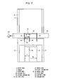
- FIG. 4 is a front elevational view showing a configuration of a dryer vacuum box according to the present embodiment.
- a side elevational view of the dryer vacuum box of the present embodiment is shown in FIG. 1 similarly to the dryer vacuum box of the first embodiment. It is to be noted that, in FIG. 4, like elements to those in the first embodiment are denoted by like reference characters.
- the dryer vacuum box of the present embodiment is different in configuration of the first vacuum box 30 from those of the first and second embodiments as seen in FIG. 4.
- the first vacuum box 30 has an installation width set equal to the full width W of the paper web 8 and is partitioned in a widthwise direction thereof into a first chamber 30A and a second chamber 30B.
- another side seal 36 is disposed between the side seals 22 and 24 disposed in alignment with the opposite ends of the paper web 8 such that the inside of the first vacuum box 30 is partitioned into two enclosed spaces, that is, the first chamber 30A and the second chamber 30B, by the side seal 36.
- the position of the side seal 36 is set such that the distance between the side seals 22 and 36 is substantially equal to the width T of the tail 8a.
- the vacuum introduction path 48 in the support pipe 40 is partitioned into two vacuum introduction paths 48a and 48b by a partition plate 49.
- the vacuum introduction path 48a and the first chamber 30A are communicated with each other by a communication hole 40a while the other vacuum introduction path 48b and the second chamber 30B are communicated with each other by another communication hole 40b.
- the vacuum introduction paths 48a and 48b are connected to different vacuum fans 50A and 50B, respectively.
- first chamber 30A and the second chamber 30B can be connected to the vacuum fans 50A and 50B, which serve as different vacuum sources from each other, independently of each other, respectively, upon paper threading of the tail 8a, required vacuum suction force can be applied to the paper threading position of the tail 8a by stopping the supply of the vacuum suction force from the vacuum fan 50B to the second chamber 30B.
- high vacuum suction force can be applied uniformly to the full width of the paper web 8. In both cases, occurrence of sticking can be suppressed.
- dryer vacuum box of the present embodiment can be modified such that it includes only the first vacuum box 30 without the provision of the second vacuum box 20 similarly as in the second embodiment.
- a dryer vacuum box in this embodiment is provided in a dryer part of a paper machine and is operable to apply vacuum suction force generated by a vacuum source through a canvas to a paper web, which is delivered with the canvas on circumferential surface of a dryer roll.
- the dryer vacuum box comprises a first vacuum box having an opening faced with surrounding area of a peeling point on the canvas, where the canvas is separated from the circumferential surface of the dryer roll, and the opening is covered by the surrounding area of the canvas so that an enclosed space is defined within the first vacuum box.
- the first vacuum box is connected with the vacuum source so that a degree of vacuum in the first vacuum box is to be set to a predetermined value.
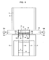
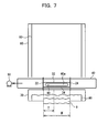
- FIGS. 5 to 7 are views showing a vacuum dryer box as a fourth embodiment of the present invention. More particularly, FIG. 5 is a schematic side elevational view showing a configuration of a dryer part in which the dryer vacuum box is incorporated, FIG. 6 is a schematic side elevational view, partly in section, showing a configuration of the dryer vacuum box, and FIG. 7 is a schematic front elevational view showing a configuration of the dryer vacuum box.
- the dryer part shown is formed as that of the two-stage deck type wherein dryer rolls are disposed in two upper and lower stages. More particularly, the dryer part includes four dryer rolls 60 to 63. The dryer rolls (top dryer rolls) 60 and 62 are disposed in the upper stage while the dryer rolls (bottom dryer rolls) 61 and 63 are disposed in the lower stage.
- An endless canvas 80 extends between and around the top dryer rolls 60 and 62 such that it runs in a loop while it is driven and/or guided by the top dryer rolls 60 and 62, canvas rolls 70 and 71 and so forth.
- another endless canvas 81 extends between and around the bottom dryer rolls 61 and 63 such that it runs in a loop while it is driven and/or guided by the dryer rolls 61 and 63, canvas rolls 72 and 73 and so forth.
- a paper web 8 is passed from the bottom canvas 81 to the top dryer roll 60. Thereupon, the paper web 8 is pressed to the top dryer roll 60 by the canvas 80. Then, the paper web 8 is spaced away from the canvas 80 on the canvas roll 70 and is now pressed to the bottom dryer roll 61 by the canvas 81. Therefore, the paper web 8 is pressed to the top dryer roll 62 by the canvas 80 and then pressed to the bottom dryer roll 63 by the canvas 81.
- Vacuum boxes 90 and 91 are disposed between the top dryer roll 60 and the canvas roll 70 in the loop of the canvas 80 and between the bottom dryer roll 61 and the canvas roll 73 in the loop of the canvas 81, respectively.
- the vacuum boxes 90 and 91 have a similar configuration to each other. Therefore, the configuration of the vacuum box 90 as a representative of the vacuum boxes 90 and 91 is described with reference to FIGS. 6 and 7.
- side seals 22 and 24 and brackets 44 and 46 are securely provided on a support pipe 40 which extends in a widthwise direction of the apparatus.
- cross seals 32 and 34 are secured to end portions of the brackets 44 and 46, respectively, such that they extend in the widthwise direction.
- the opposite ends of the brackets 44 and 46 in the widthwise direction are assembled to the side seals 22 and 24 (in FIG. 6, the side seal 22 is shown partly cutaway in order to show the inside of the first vacuum box 90).
- the cross seals 32 and 34 and the side seals 22 and 24 are held in contact with the canvas 80 wrapped around the top dryer roll 60 in such a manner as to define an enclosed space 90.
- the enclosed space 90 functions as a vacuum box 90 (first vacuum box according to the present invention).
- a communication hole 40a for communicating an internal space 48 of the support pipe 40 and the inside of the vacuum box 90 with each other is provided in a surface of the support pipe 40 between positions at which the brackets 44 and 46 are securely provided.
- the internal space 48 of the support pipe 40 is connected to a vacuum fan (vacuum source) 50.
- the side seals 22 and 24 are disposed such that they are aligned with the opposite ends in the widthwise direction of the paper web 8 which runs on the dryer rolls, and the contacting position between the cross seal 32 on the upper side and the canvas 80 is set to a position a little on the upstream side with respect to a peeling point at which the canvas 80 is spaced away from the top dryer roll 60 while the contacting position between the cross seal 34 on the lower side and the canvas 80 is set to another position a little on the downstream side with respect to the peeling point.
- the vacuum box 90 is formed as an enclosed space which includes as part of an inner face thereof a surface of the canvas 80 in the proximity of the peeling point at which the canvas 80 is spaced away from the top dryer roll 60.
- the vacuum box as the fourth embodiment of the present invention is configured in such a manner as described above, it has an advantage that it can prevent sticking similarly to those of the embodiments described hereinabove.
- the vacuum box of the present embodiment is configured such that it includes the vacuum boxes 90 and 91 (first vacuum boxes according to the present invention) each formed as a single member, it may otherwise be configured similarly to those of the embodiments described above such that a second vacuum box which includes as part of an inner face thereof the surfaces of draw portions of the canvases 80 and 81 extending from the dryer rolls 60 and 61 to the canvas rolls 70 and 73 on the downstream side of the dryer rolls 60 and 61 in the paper web running direction is provided on the outside of the first vacuum box.
- a support pipe separate from the support pipe 40 is mounted such that it extends through the second vacuum box and a negative pressure of a lower degree of vacuum than the negative pressure to be applied to the first vacuum box is applied to the inside of the second vacuum box through the support pipe.
- the paper web 8 can be sucked to the canvas not only in the proximity of but also around the peeling point (the peeling point when no sticking occurs) of the paper web 8 from the dryer roll.
- the second vacuum box can suck the paper web 8 efficiently with a degree of vacuum lower than that of the first vacuum box.
- the vacuum box of the fourth embodiment similarly as in the third embodiment described hereinabove such that the side seal 36 is disposed such that the distance thereof to the side seal 22 is substantially equal to the width T of the tail 8a to partition the inside of the first vacuum box into a first chamber and a second chamber and supply vacuum suction force to the first chamber and the second chamber independently of each other.
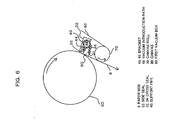
- FIG. 8 is a schematic side elevational view showing a configuration of a dryer part in which a dryer vacuum box as a fifth embodiment of the present invention is incorporated. It is to be noted that, in FIG. 8, a gap is shown provided among a web 8, a canvas 170 and dryer rolls 161 to 163 for the convenience of illustration.
- a dryer vacuum box of the present invention is incorporated in the dryer part of the double deck type described hereinabove as the prior art apparatus with reference to FIG. 11.
- those elements which have been described in the description of the prior art apparatus are denoted by like reference numerals and overlapping description of them is omitted herein to avoid redundancy.
- a first vacuum box 200 is disposed between the dryer rolls 160 and 161 and also between the dryer rolls 162 and 163 in the loop of the canvas 170. Since both of the vacuum boxes 200 are configured similarly to each other, description is given below of a configuration of an upstream side one of the vacuum boxes 200 as a representative of them.
- the vacuum box 200 is formed as an enclosed space which has such a transverse sectional shape as seen in FIG. 8 and extends over the full width of the paper web 8.
- the vacuum box 200 is partitioned into a first chamber 202 and a second chamber 203 by a partition wall 201 disposed in the proximity of a peeling point at which the canvas 170 is peeled from the dryer roll 160.
- a casing which forms the first chamber 202 has an opening 202a provided at a location thereof which faces the peeling point.
- a pair of cross seals 202b and 202c are attached to the casing at front and rear locations with respect to the opening 202a such that the contacting position between the cross seal 202b on the upstream side and the canvas 170 is set to a position a little on the upstream side with respect to the peeling point while the contacting position between the cross seal 202c on the downstream side and the canvas 170 is set to another position a little on the downstream side with respect to the peeling position.
- the casing which forms the second chamber 203 has, at a location thereof which faces the dryer roll 161, an opening 203a formed therein which is elongated in an axial direction of the dryer roll 161.
- a cross seal 203b is disposed on the opposite side to the cross seal 202c with respect to the opening 203a.
- Different vacuum sources not shown are individually connected to the chambers 202 and 203 such that the inside of the first chamber 202 is controlled to a comparatively high degree of vacuum while the inside of the second chamber 203 is controlled to a comparatively low degree of vacuum.
- the dryer vacuum box as the fifth embodiment of the present invention is configured in such a manner as described above, high suction force can be applied to the paper web 8 through the canvas 170 between the cross seals 202b and 202c by the first chamber 202 to peel the paper web 8 from the dryer roll 160 with certainty while the paper web 8 can be sucked stably to the canvas 170 between the cross seals 202c and 203b by the second chamber 203.
- the dryer vacuum box of the third embodiment includes the vacuum fans 50A and 50B separate from each other as vacuum sources connected to the first chamber 30A and the second chamber 30B, respectively, it may be modified such that it includes a single vacuum fan and a control valve or valves are used to control supply/stop of vacuum suction force from the vacuum fan to the first chamber 30A and the second chamber 30B independently of each other.
Landscapes
- Paper (AREA)
Abstract
Description
Claims (7)
- A dryer vacuum box, provided in a dryer part of a paper machine, for applying vacuum suction force generated by a vacuum source (50; 50A, 50B) through a canvas (6; 80, 81; 170) to a paper web (8), which is delivered with the canvas (6; 80, 81; 170) on circumferential surface of a dryer roll (2, 4; 60 to 63; 160 to 165), characterized in that
it comprises a first vacuum box (30; 90, 91; 200) having an opening faced with surrounding area of a peeling point on the canvas(6; 80, 81; 170), where the canvas(6; 80, 81; 170) is separated from the circumferential surface of the dryer roll (2, 4; 60 to 63; 160 to 165), said opening being covered by the surrounding area of the canvas(6; 80, 81; 170) so that an enclosed space is defined within said first vacuum box (30; 90, 91; 200);
said first vacuum box (30; 90, 91; 200) being connected with the vacuum source (50; 50A, 50B) so that a degree of vacuum in said first vacuum box (30; 90, 91; 200) is to be set to a predetermined value. - The dryer vacuum box as set forth in claim 1, characterized in that
it further comprisesa second vacuum box (20) having an opening faced with a draw area of the canvas (6; 80, 81; 170), which area lies between the dryer roll (2; 60, 61; 160, 162) and another roll (10; 70, 73; 161, 163) on the downstream side along a path of the paper web (8), said opening being covered by the draw area of the canvas (6; 80, 81; 170) so that another enclosed space is defined within said second vacuum box (20) and that vacuum suction force is applied to inside of said second vacuum box (20);
said first vacuum box (30; 90, 91; 200) being provided in said second vacuum box (20), and the degree of vacuum in said first vacuum box (30; 90, 91; 200) being set higher than a degree of vacuum in said second vacuum box (20). - The dryer vacuum box as set forth in claim 2, characterized in that
said another roll is a vacuum roll (10); and the vacuum suction force generated from said vacuum roll (10) is applied to the inside of said second vacuum box (20). - The dryer vacuum box as set forth in any one of claims 1 to 3, characterized in that said first vacuum box (30; 90, 91; 200) has a width substantially equal to the width (T) of a tail (8a) of the paper web (8) upon paper threading and is provided at a paper threading position of the tail (8a).
- The dryer vacuum box as set forth in any one of claims 1 to 3, characterized in that said first vacuum box (30; 90, 91; 200) has a width substantially equal to the full width (W) of the paper web (8).
- The dryer vacuum box as set forth in claim 5, characterized in that the inside of said first vacuum box (30) is partitioned in a widthwise direction into a first chamber (30A) and a second chamber (30B) which can be connected to said vacuum source (50; 50A, 50B) independently of each other, and that said first chamber (30A) has a width substantially equal to the width (T) of the tail (8a) upon paper threading and provided at a paper threading position of the tail (8a).
- The dryer vacuum box as set forth in claim 1, characterized in that the inside of said first vacuum box (200) is partitioned in a paper web running direction into a first chamber (202) and a second chamber (203) which can be connected to said vacuum source independently of each other.
Applications Claiming Priority (4)
| Application Number | Priority Date | Filing Date | Title |
|---|---|---|---|
| JP2002157672 | 2002-05-30 | ||
| JP2002157672 | 2002-05-30 | ||
| JP2002216775 | 2002-07-25 | ||
| JP2002216775A JP3723158B2 (en) | 2002-05-30 | 2002-07-25 | Dryer vacuum box |
Publications (2)
| Publication Number | Publication Date |
|---|---|
| EP1367173A2 true EP1367173A2 (en) | 2003-12-03 |
| EP1367173A3 EP1367173A3 (en) | 2004-04-14 |
Family
ID=29422467
Family Applications (1)
| Application Number | Title | Priority Date | Filing Date |
|---|---|---|---|
| EP03012372A Withdrawn EP1367173A3 (en) | 2002-05-30 | 2003-05-30 | Dryer vacuum box |
Country Status (4)
| Country | Link |
|---|---|
| US (1) | US6952888B2 (en) |
| EP (1) | EP1367173A3 (en) |
| JP (1) | JP3723158B2 (en) |
| CN (1) | CN1255602C (en) |
Cited By (3)
| Publication number | Priority date | Publication date | Assignee | Title |
|---|---|---|---|---|
| WO2007085699A1 (en) | 2006-01-30 | 2007-08-02 | Metso Paper, Inc. | Method and device in a dryer section of a fibre-web machine, such as a paper or board machine |
| EP2135995A2 (en) | 2008-06-17 | 2009-12-23 | Andritz AG | Method and device for transferring a material web |
| WO2011036019A1 (en) * | 2009-09-23 | 2011-03-31 | Voith Patent Gmbh | Stabilizing apparatus for guiding a fibrous web and drying apparatus having a stabilizing apparatus of this type |
Families Citing this family (5)
| Publication number | Priority date | Publication date | Assignee | Title |
|---|---|---|---|---|
| JP4633423B2 (en) | 2004-09-15 | 2011-02-16 | 株式会社トプコン | Optical image measuring device |
| JP5058627B2 (en) | 2007-02-26 | 2012-10-24 | 株式会社トプコン | Fundus observation device |
| CN101910512B (en) * | 2007-12-31 | 2012-03-28 | 美卓造纸机械公司 | Operative member of a paper machine or paper board machine or finishing machine, related negative pressure device and method for saving energy |
| AT506408B1 (en) * | 2008-06-17 | 2009-09-15 | Andritz Ag Maschf | DEVICE AND METHOD FOR TRANSFERRING A MATERIAL TRACK |
| AT506407B1 (en) * | 2008-06-17 | 2009-09-15 | Andritz Ag Maschf | DEVICE AND METHOD FOR TRANSFERRING A MATERIAL TRACK |
Citations (3)
| Publication number | Priority date | Publication date | Assignee | Title |
|---|---|---|---|---|
| DE4314475A1 (en) * | 1993-05-03 | 1993-12-23 | Voith Gmbh J M | Paper web passage through drying section - has sealing bar structure at deflection roller for roller surface recesses to generate underpressure without roller suction |
| US5600897A (en) * | 1993-08-06 | 1997-02-11 | J.M. Voith Gmbh | Mixed dryer section including single-tier and double-tier drying groups with automatic ropeless threading |
| EP1193343A2 (en) * | 1996-01-30 | 2002-04-03 | Voith Paper Patent GmbH | Device for guiding a fibrous web in a single row drying section |
Family Cites Families (10)
| Publication number | Priority date | Publication date | Assignee | Title |
|---|---|---|---|---|
| US4876803A (en) | 1987-02-13 | 1989-10-31 | Beloit Corporation | Dryer apparatus for drying a web |
| FI80491C (en) | 1987-09-02 | 1990-06-11 | Valmet Paper Machinery Inc | FOERFARANDE OCH TORKNINGSGRUPP I MAONGCYLINDERTORKEN AV EN PAPPERSMASKIN. |
| FI82850C (en) | 1989-03-21 | 1991-04-25 | Valmet Paper Machinery Inc | Method and apparatus in the drying section of a coating machine or paper machine |
| DE4141296A1 (en) | 1991-12-14 | 1993-06-17 | Voith Gmbh J M | Papermaking drying section - has suction box with structured sealing bar positions to detach web and carrier belt together from the drying cylinder surface |
| DE4142524A1 (en) * | 1991-12-21 | 1993-06-24 | Voith Gmbh J M | DRY LOT |
| US5515619A (en) * | 1993-08-06 | 1996-05-14 | J.M. Voith Gmbh | Flexibly mounted sealing strips of a vacuum roll for a web dryer |
| DE19615227A1 (en) * | 1996-04-18 | 1997-10-23 | Voith Sulzer Papiermasch Gmbh | Machine for the production of a material web |
| US5873180A (en) | 1996-09-25 | 1999-02-23 | Beloit Technologies, Inc. | Papermaking dryer section with partitioned vacuum box for threading |
| DE19723163A1 (en) * | 1997-06-03 | 1998-12-10 | Voith Sulzer Papiermasch Gmbh | Dryer section |
| FI110625B (en) | 1999-02-22 | 2003-02-28 | Metso Paper Inc | Blowing device in paper machine or equivalent |
-
2002
- 2002-07-25 JP JP2002216775A patent/JP3723158B2/en not_active Expired - Fee Related
-
2003
- 2003-05-28 US US10/446,016 patent/US6952888B2/en not_active Expired - Fee Related
- 2003-05-30 EP EP03012372A patent/EP1367173A3/en not_active Withdrawn
- 2003-05-30 CN CN03140638.6A patent/CN1255602C/en not_active Expired - Fee Related
Patent Citations (3)
| Publication number | Priority date | Publication date | Assignee | Title |
|---|---|---|---|---|
| DE4314475A1 (en) * | 1993-05-03 | 1993-12-23 | Voith Gmbh J M | Paper web passage through drying section - has sealing bar structure at deflection roller for roller surface recesses to generate underpressure without roller suction |
| US5600897A (en) * | 1993-08-06 | 1997-02-11 | J.M. Voith Gmbh | Mixed dryer section including single-tier and double-tier drying groups with automatic ropeless threading |
| EP1193343A2 (en) * | 1996-01-30 | 2002-04-03 | Voith Paper Patent GmbH | Device for guiding a fibrous web in a single row drying section |
Cited By (6)
| Publication number | Priority date | Publication date | Assignee | Title |
|---|---|---|---|---|
| WO2007085699A1 (en) | 2006-01-30 | 2007-08-02 | Metso Paper, Inc. | Method and device in a dryer section of a fibre-web machine, such as a paper or board machine |
| EP1979535A1 (en) * | 2006-01-30 | 2008-10-15 | Metso Paper, Inc. | Method and device in a dryer section of a fibre-web machine, such as a paper or board machine |
| EP1979535A4 (en) * | 2006-01-30 | 2013-12-18 | Metso Paper Inc | Method and device in a dryer section of a fibre-web machine, such as a paper or board machine |
| EP2135995A2 (en) | 2008-06-17 | 2009-12-23 | Andritz AG | Method and device for transferring a material web |
| EP2135995A3 (en) * | 2008-06-17 | 2013-06-12 | Andritz AG | Method and device for transferring a material web |
| WO2011036019A1 (en) * | 2009-09-23 | 2011-03-31 | Voith Patent Gmbh | Stabilizing apparatus for guiding a fibrous web and drying apparatus having a stabilizing apparatus of this type |
Also Published As
| Publication number | Publication date |
|---|---|
| CN1255602C (en) | 2006-05-10 |
| CN1469007A (en) | 2004-01-21 |
| US20030230002A1 (en) | 2003-12-18 |
| EP1367173A3 (en) | 2004-04-14 |
| JP2004052195A (en) | 2004-02-19 |
| US6952888B2 (en) | 2005-10-11 |
| JP3723158B2 (en) | 2005-12-07 |
Similar Documents
| Publication | Publication Date | Title |
|---|---|---|
| PL195509B1 (en) | Method and apparatus in the drying section of a paper machine or the like | |
| FI76142C (en) | FICKVENTILATIONSFOERFARANDE OCH -ANORDNING I EN PAPPERSMASKINS MAONGCYLINDERTORK. | |
| FI65460C (en) | FOER FARANDE OCH ANORDNING VID PRESS- ELLER TORKPARTIET I EN PAPERSMASKIN | |
| US4551203A (en) | Method and arrangement for guiding a paper web from the press section to the drying section | |
| JPH04316693A (en) | Drying section | |
| EP1367173A2 (en) | Dryer vacuum box | |
| JPH03502218A (en) | Dryer device for drying web | |
| JPS61245394A (en) | Method for acting negative pressure on fan shaped part of suction roll and suction roll | |
| US6533899B1 (en) | Device for conveying and guiding a lead-in strip of a web in a paper machine | |
| US5438765A (en) | Method and apparatus for eliminating the flutter of a paper web in the dryer section of a papermaking machine between two single felt configurations therein | |
| FI104644B (en) | Method and apparatus in a paper machine for transferring a web from a molding portion to a pressing portion | |
| US8117765B2 (en) | Apparatus and method of sealing of a pocket space between drying cylinders in a paper machine or a board machine | |
| US6325320B1 (en) | Winding device and process for winding a web material | |
| KR100403987B1 (en) | Paper dryer with multiple roll vacuum chamber | |
| WO2010084241A1 (en) | Method and arrangement for facilitating web threading in a paper machine's drying section | |
| JP2011508111A (en) | Apparatus and method for controlling negative pressure in a drying section of a paper machine or the like | |
| FI121715B (en) | Method and apparatus for threading a web in a drying section of a papermaking machine or the like | |
| US5820733A (en) | Device to stabilize sheet between press section and dryer section of a paper-making machine | |
| CA2122350A1 (en) | A Pick-Up Roll Apparatus | |
| FI75892B (en) | ANORDNING I TORKPARTIET ELLER I OMRAODET MELLAN PRESS- OCH TORKPARTIET HOS EN PAPPERSMASKIN. | |
| US20020124429A1 (en) | Apparatus for ventilating a pocket of a dryer section of a paper machine | |
| JP3269076B2 (en) | Tail paper wrap prevention device | |
| CA2427591C (en) | Device for conveying and guiding a lead-in strip of a web in a paper machine | |
| CN101139807B (en) | The smoothing method of wet web and the press section for paper machine | |
| FI122926B (en) | Arrangement and procedure for saving energy in dryer section of paper machine or equivalent |
Legal Events
| Date | Code | Title | Description |
|---|---|---|---|
| PUAI | Public reference made under article 153(3) epc to a published international application that has entered the european phase |
Free format text: ORIGINAL CODE: 0009012 |
|
| AK | Designated contracting states |
Kind code of ref document: A2 Designated state(s): AT BE BG CH CY CZ DE DK EE ES FI FR GB GR HU IE IT LI LU MC NL PT RO SE SI SK TR |
|
| AX | Request for extension of the european patent |
Extension state: AL LT LV MK |
|
| PUAL | Search report despatched |
Free format text: ORIGINAL CODE: 0009013 |
|
| AK | Designated contracting states |
Kind code of ref document: A3 Designated state(s): AT BE BG CH CY CZ DE DK EE ES FI FR GB GR HU IE IT LI LU MC NL PT RO SE SI SK TR |
|
| AX | Request for extension of the european patent |
Extension state: AL LT LV MK |
|
| 17P | Request for examination filed |
Effective date: 20040423 |
|
| AKX | Designation fees paid |
Designated state(s): DE FI |
|
| 17Q | First examination report despatched |
Effective date: 20071022 |
|
| STAA | Information on the status of an ep patent application or granted ep patent |
Free format text: STATUS: THE APPLICATION IS DEEMED TO BE WITHDRAWN |
|
| 18D | Application deemed to be withdrawn |
Effective date: 20080304 |