EP1366935A1 - Device for generating a temperature controlled air flow and appliance comprising said device - Google Patents
Device for generating a temperature controlled air flow and appliance comprising said device Download PDFInfo
- Publication number
- EP1366935A1 EP1366935A1 EP03011602A EP03011602A EP1366935A1 EP 1366935 A1 EP1366935 A1 EP 1366935A1 EP 03011602 A EP03011602 A EP 03011602A EP 03011602 A EP03011602 A EP 03011602A EP 1366935 A1 EP1366935 A1 EP 1366935A1
- Authority
- EP
- European Patent Office
- Prior art keywords
- duct
- shutter
- air
- flap
- cold air
- Prior art date
- Legal status (The legal status is an assumption and is not a legal conclusion. Google has not performed a legal analysis and makes no representation as to the accuracy of the status listed.)
- Granted
Links
Images


Classifications
-
- B—PERFORMING OPERATIONS; TRANSPORTING
- B60—VEHICLES IN GENERAL
- B60H—ARRANGEMENTS OF HEATING, COOLING, VENTILATING OR OTHER AIR-TREATING DEVICES SPECIALLY ADAPTED FOR PASSENGER OR GOODS SPACES OF VEHICLES
- B60H1/00—Heating, cooling or ventilating [HVAC] devices
- B60H1/00642—Control systems or circuits; Control members or indication devices for heating, cooling or ventilating devices
- B60H1/00664—Construction or arrangement of damper doors
-
- B—PERFORMING OPERATIONS; TRANSPORTING
- B60—VEHICLES IN GENERAL
- B60H—ARRANGEMENTS OF HEATING, COOLING, VENTILATING OR OTHER AIR-TREATING DEVICES SPECIALLY ADAPTED FOR PASSENGER OR GOODS SPACES OF VEHICLES
- B60H1/00—Heating, cooling or ventilating [HVAC] devices
- B60H1/00007—Combined heating, ventilating, or cooling devices
- B60H1/00021—Air flow details of HVAC devices
- B60H1/00064—Air flow details of HVAC devices for sending air streams of different temperatures into the passenger compartment
-
- B—PERFORMING OPERATIONS; TRANSPORTING
- B60—VEHICLES IN GENERAL
- B60H—ARRANGEMENTS OF HEATING, COOLING, VENTILATING OR OTHER AIR-TREATING DEVICES SPECIALLY ADAPTED FOR PASSENGER OR GOODS SPACES OF VEHICLES
- B60H1/00—Heating, cooling or ventilating [HVAC] devices
- B60H1/00642—Control systems or circuits; Control members or indication devices for heating, cooling or ventilating devices
- B60H1/00814—Control systems or circuits characterised by their output, for controlling particular components of the heating, cooling or ventilating installation
- B60H1/00821—Control systems or circuits characterised by their output, for controlling particular components of the heating, cooling or ventilating installation the components being ventilating, air admitting or air distributing devices
- B60H1/00835—Damper doors, e.g. position control
- B60H1/00842—Damper doors, e.g. position control the system comprising a plurality of damper doors; Air distribution between several outlets
-
- B—PERFORMING OPERATIONS; TRANSPORTING
- B60—VEHICLES IN GENERAL
- B60H—ARRANGEMENTS OF HEATING, COOLING, VENTILATING OR OTHER AIR-TREATING DEVICES SPECIALLY ADAPTED FOR PASSENGER OR GOODS SPACES OF VEHICLES
- B60H1/00—Heating, cooling or ventilating [HVAC] devices
- B60H1/00007—Combined heating, ventilating, or cooling devices
- B60H1/00021—Air flow details of HVAC devices
- B60H2001/0015—Temperature regulation
- B60H2001/00164—Temperature regulation with more than one by-pass
Definitions
- the invention relates to the field of heating devices and / or air conditioning.
- a generation device a flow of air at a regulated temperature, in particular for a cabin heating and / or air conditioning system of a vehicle, having a mixing chamber and outputs of air connected to the mixing chamber, the generation comprising at least one cold air duct, at least a hot air duct in which a radiator is arranged heating, means for distributing a main air flow generated by the heater between the air duct cold and hot air duct.
- heaters and / or air conditioning the passenger compartment of a vehicle which includes a housing housing a blower capable of generating an air flow which is then distributed between a hot air duct and a cold air duct.
- a heating radiator mounted in the hot air duct allows to heat the air before introducing it into the passenger compartment motor vehicle.
- the ventilation and / or heating is fitted with a air distribution which distributes the air flow main in variable proportions between the hot air duct and the cold air duct.
- the distribution device also makes it possible to make operate the appliance in an "all hot” mode and in a “all cold” mode.
- the hot and cold air flows are then remixed in a device chamber called the mixing, comprising several outlets which deliver air to temperature set at appropriate points in the passenger compartment motor vehicle, for example a defrost outlet, a ventilation outlet and feet heating outlet, shutters being provided in each of these outputs to control selectively the above outputs.
- the distribution panes allow you to define different air distribution configurations based on comfort aerothermal system desired by the occupant (s) of the vehicle.
- the device for generating a flow of air at temperature set should allow flexibility of focus heating of the heater. In particular, it must allow to channel and direct the air flow towards preferential places to ensure a good distribution according to the different outputs and to precisely adjust the relative amount of hot and cold air and allow good mixture of hot and cold air flows for each outlet.
- a disadvantage of the devices of heaters currently known is that they do not allow to route enough cold air to all room exits mixing. For example, if the cold air duct is arranged at the bottom of the appliance, the outlets located at the upper part of the mixing chamber, usually the defrost outlet, will not be adequately supplied with cold air. These devices therefore do not allow a good setting at the aerothermal point.
- the object of the invention is to provide a heating appliance. and / or air conditioning of the passenger compartment of the motor vehicle and a device for generating a flow of air at temperature settled that overcomes these disadvantages.
- the device for generating an air flow comprises at least a leakage pipe allowing at least one cold air leak injected into the mixing chamber and a calibration device to adjust the cold air leak, this calibration device being actuated by a control independent of the configuration of the main air flow distribution means between the hot air duct and the cold air duct.
- This device has two advantages. On the one hand, leads it. allows to bring a cold air leak rate in a place in the mixing room that could't be supplied with cold air in the absence of this duct. Through therefore, it allows aerothermal tuning satisfactory for outlets near the conduit leak.
- the leakage pipe can be arranged in one place any suitable device. For example, if the conduit cold air is located in the lower part of the appliance, the leakage duct will be located opposite the upper part of device
- the leakage pipe can be placed also, for example, either laterally with respect to the duct hot air, either above and laterally from the hot air duct.
- the leak rate can be adjusted independently the configuration of the air flow distribution means main. It can therefore be adapted to the mode of dissemination of air in the passenger compartment, regardless of the set temperature air.
- control of the calibration member is linked to the kinematics of one of the distribution components of the heater.
- the calibration device is linked to the kinematics of the defrost duct flap.
- the calibration member is made in one piece with one of the distribution flaps of the appliance, for example the flap of the defrost duct.
- the calibration member can be constituted by a piece separate from the distribution shutters.
- the device comprises a independently controlled leakage shutter valve the configuration of the distribution means.
- the control of the shutter valve is linked to the configuration of the distribution means.
- the distribution means can be produced in different ways ways. They can consist, for example, of a simple flag or butterfly mixing flap.
- the means of distribution have at least one panel with at least one opening disposed in the hot air duct, and a blanking plate movable between an open position in which it does not not cover the panel opening and a closed position in which it closes the panel, at least one flap of adjustment of the passage section of the mobile cold air duct between an open position and a closed position, a control mechanism for synchronously controlling the displacement of the shutter plate and displacement of the shutter for adjusting the cross section of the cold air duct between their open position and their closed position.
- the panel has a plurality of openings and the shutter plate a plurality of cutouts, the openings of the panel and blanks of the blanking plate being arranged relative to each other in such a way that the conduit hot air is shut off when the shutter plate is in its shutter position.
- the shutter plate moves according to a combined movement of translation and rotation, the plate shutter being moved away from the panel in the open position.
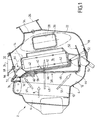
- FIG. 1 a general sectional view of a heating, air conditioning and ventilation equipment, designated by reference 2. It has a housing 4 in which is provided with an air inlet 6 of an air flow main schematized by the arrow 8. An evaporator 10 is mounted in a main conduit 12 of the housing 4. The conduit main divides into a hot duct 14 in which is mounted a heating radiator 16 and a cold pipe 18 parallel to the hot duct 14 and located below it. The main air flow 8 can be distributed in proportions adjustable between the hot pipe 14 and the cold pipe 18.
- the shutter functions of the hot duct 14 and the duct cold 18, as well as the air flow distribution function main 8 between these two conduits are obtained by means of a distribution device 38, also called distribution device mixing.
- This device could be constituted, conventionally, by a flag flap or a butterfly flap.
- the distribution device 38 comprises a panel 40 mounted in a fixed position in the housing 4 and comprising openings 42, three in number in the example.
- the distribution device 38 also includes a plate shutter 44 having openings 46. The plate shutter 44 is movable between a shutter position and an open position.
- the openings in panel 40 and the blanking plate openings do not overlap, so that the overlap of the blanking plate and the panel completely closes the hot duct 14.
- the open position shown in solid lines on the figure, the blanking plate is spaced from the panel 40 of so that the openings of the panel and the openings of the plate do not overlap, allowing the passage of air, as shown by arrow 48.
- the distribution device 38 also includes an element sealing the cold air duct 18.
- this element is constituted by a flap 50 rotatably mounted around its axis 52.
- the flap 50 is able to pivot between a position open, shown in solid lines in the figure, and a shutter position, shown in dashed lines, in which the ends of the flap 50 come to bear on fitted in the housing to seal the duct cold 18 tightly.
- a position open shown in solid lines in the figure
- a shutter position shown in dashed lines
- the rotation movement of the flap 50 can be controlled from the exterior of the housing 4, for example by means of the axis 52 of which the flap 50 is integral.
- Part 50 includes an arm 54 whose free end is articulated at the end bottom of the shutter plate 44.
- the shutter plate 44 has two pins 58 which are each capable of sliding in a ramp 60 arranged in the housing 4.
- the device for generating a temperature controlled air flow has a leakage channel 64 suitable for allowing the passage of a cold air leak, such as shown diagrammatically by arrow 65.
- the escape channel 64 is located at the top of the device, while the cold air duct 18 is located at the bottom of the appliance, below the heating radiator 16.
- a shutter 66 in the example a butterfly flap mounted turning around its axis 68, allows to calibrate the flow of air leakage through leakage duct 64.
- the shutter throttle valve 66 can pivot between a fully closed position, in which it prohibits any passage of cold air through the duct 64, in a fully open position, in which the duct is completely free for the passage of a leak cold air.
- the position of the flap calibration 66 is controlled independently of the position of the air flow distribution means, i.e., in the example shown, the shutter plate 44 and the butterfly flap 50.
- the shutter plate and the flap 50 are mechanically linked to each other.
- the degree of openness of one of the organs determines the degree of openness of the other unequivocally. So when the flap 50 is fully open, the shutter plate completely closes the passage hot air and vice versa.
- the position of the calibration flap 66 can be adjusted independently of the air flow distribution.
- leakage channel 64 may be completely open while the cold air duct 18 is entirely or partially closed.
- the hot air flow 46 and the air flow cold 51 then mix in a chamber 22, called mixing chamber, located downstream of the hot and cold conduits 16 and 18.
- This mixing chamber 22 is shown schematically by an oval in broken lines. From the mixing chamber 22, the air is distributed at temperature suitable for the three exits 24, 26 and 28 mentioned previously.
- the device also includes a valve.
- shutter 72 movable between an open position and a closed position. In its closed position, the valve shutter closes a passage opening 74 located at the entrance of the leakage duct 64. The duct 64 is then closed, whatever whatever the position of the calibration flap 66. On the contrary, in the open position of the shutter valve 72, the flow of leakage is adjusted by the calibration flap 66.
- the valve shutter 72 can be controlled by means of air distribution. It can, for example, as shown in Figure 1, be mounted on a rod 76 connected to the upper end of the blanking plate 44. In others terms, the calibration flap 66 and the shutter valve 72 are controlled independently of each other. While the calibration component is generally linked to the configuration the shutter valve, on the contrary, is linked to the air distribution configuration.
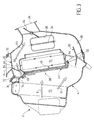
- FIG. 2 a sectional view of a particular embodiment of the device of the invention.
- the peculiarity of this device lies in the fact that the flap 32 of the defrost outlet 24 and the flap 66 of cold air leak calibration are formed of a single room. They constitute a one-piece adjustment assembly 82 which pivots around a common axis 84. Sections 32 and 66 work in the same direction.
- the defrost outlet 24 is closed when the flap 66 closes the leakage duct 64.
- the adjustment of the leakage output is linked to the distribution function and, more specifically, to the defrost function.
- the calibration component 66 could be linked to ventilation flap 34 or outlet adjustment flap 36 heating feet.
- the device is shown in mode "foot heating". Indeed, the flap 36 for adjusting the output 28 for foot heating is in the open position, while the flap 34 of the ventilation outlet 26 is in position closed. Furthermore, the air distribution device 38 is in the "all cold” position. Indeed, as we can observe, the shutter plate 44 closes the openings of the panel 40 of so that the hot air duct 18 is fully closed.
- the presence of a cold air leak is not useful in principle because it is a simple distribution method, that is to say that the air is distributed by an outlet single, heating output feet in configuration shown, but it could also be the output of ventilation. As a result, there is no stratification of temperature to be managed between the various outputs. That's the reason for which the calibration flap 66 closes the conduit 64. However, a small leak of cold air could still be envisaged to perfect the temperature uniformity in the output concerned, the heating output feet 28 in Figure 2.
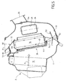
- the device of the invention is located in a two-stage air distribution mode, namely by foot-ventilation position.
- the output of ventilation 26 and the heating outlet feet 28 are open simultaneously.
- the defrost outlet 24 is closed.
- the means of distributing the flow main air are in the "all cold" position, so that the entire main air flow 8 passes through the air duct cold 18, as shown by arrow 51, except a cold air leak, represented by arrow 65, flowing through the leakage duct 64.
- the flap calibration 66 allows a passage of cold air under its part rear to route a slight flow of cold air 65 into the mixing chamber and mainly towards the exit of ventilation 26. This air flow thus contributes to generating the temperature stratification required between the outlet ventilation and heating output feet affected by this distribution mode.
- the importance of air leakage 65 is calibrated by the degree of opening of the shutter 66.
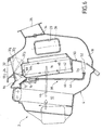
- the air distribution device is also in a two-level distribution mode, namely foot heating and defrosting. Part 34 of the exit from ventilation 26 is closed, while the flap 36 of the outlet heating feet and flap 32 of the defrost outlet 24 are open.
- the air distribution device 38 is in "all cold" configuration. In this configuration, it is the defrost flap 32, not flap 66, which ensures the air leakage calibration 65.
- the defrost flap 32 allows a passage of cold air under its front part so to bring a light flow of cold air into the mixing, and mainly to defrost outlet 24, such as shown schematically by arrow 84.
- This air flow 84 thus contributes to cool the temperature within the defrost outlet 24 in order to satisfy the requirement of balance or stratification required temperature between the defrost outlet and the heating output feet concerned by this mode of distribution.
- the extent of the air leak 84 is calibrated by the passage section resulting from the degree of opening of the flap 32 and therefore the passage section between the front end of the shutter and the housing 4.
- the air distribution device is in "defrost” mode.
- the ventilation flaps 34 and 36 of heating feet are closed, while the defrost flap 32 is in the open position.
- the air distribution device 38 is in "all cold” mode. In this distribution mode, there it is not useful to foresee a cold air leak towards the mixing chamber 22 (see Figure 1) because it is a mode of simple distribution, i.e. a mode in which the air is diffused by a single outlet, the defrost outlet 24. It there is therefore no temperature stratification to manage between several outings. A small air leak could nevertheless be considered to perfect the temperature uniformity at within the defrost outlet 24.
- the defrosting flap 32 can take any possible position between the fully closed position shown in solid lines, and the fully open position 32 3 shown in phantom. It can thus be partially open, as shown by positions 32 1 and 32 2 .
- the leakage duct 64 is closed.
- it is in the partially open position like positions 32 1 and 32 2 , cold air leakage is possible through the leakage duct 64.
- the valve 72 When the plate 44 completely or partially blocks the openings 42 of the panel 40, the valve 72 is spaced from the opening passage 74, thus allowing air circulation through the leakage duct 64. On the contrary, in the "all hot" position, the valve 72 rests on its seat provided in the housing 4 and closes the passage duct 64. Thanks to this arrangement, the entire air flow passes through the heating radiator, from so that the maximum thermal power of the latter can be used to heat the passenger compartment of the vehicle.
- Valve 72 can also help calibrate the leak cold air, mainly when the shutter plate 44 leaves the "all hot" position.
- the location, dimensions, number, shape of the duct additional cold air leakage 64, from inlet 74 of this conduit, and the shutter valve 72 can be adapted to needs of the function and the space available in the housing.
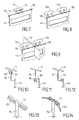
- FIG. 7 shows a view schematic in perspective of a shutter valve 72 rectangular located in the center of the housing 4 of the heating and / or air conditioning.
- Figure 8 shows a schematic perspective view of a device comprising two valves 72a and 72b in the shape of an ellipse, located laterally in the housing 4 of the device.
- Figure 9 shows a device similar to that of FIG. 8 in which the heating and / or air conditioning unit housing is divided by a partition 73 to allow distribution right / left thus creating two air leakage channels, respectively in the right and left sides of the passenger compartment vehicle.
- the shutter valve 72 of the additional cold air duct 66 can be integrated into the shutter plate 44, as in the examples described above, or reported on this plate, in constituting an additional part.
- the shutter valve can be fixed, for example clipped or screwed. It can also be articulated for better adapt, for example when moving, to the environment of the additional cold air duct 66.
- Figures 10, 11 and 12 show three examples of articulated connection.
- the shutter valve 72 comprises one or two fixing lugs 88.
- a rod 90 is mounted in a bracket at the upper end of the obturating plate 44.
- the rod 90 carries an axis 92 which passes through the lugs 88
- the shutter valve 72 carries one or two rods 94 having an axis 96 at its end.
- the axis 96 pivots in an orifice provided in one or more lugs 98 mounted at the upper end of the obturating plate 44.
- FIG. 10 the shutter valve 72 comprises one or two fixing lugs 88.
- a rod 90 is mounted in a bracket at the upper end of the obturating plate 44.
- the rod 90 carries an axis 92 which passes through the lugs 88
- the shutter valve 72 carries one or two rods 94 having an axis 96 at its end.
- the axis 96 pivots in an orifice provided in
- the shutter valve 72 carries a bent rod 97 whose end is articulated on the obturator plate 44 by means of an overmoulding 99 of elastic material, for example of SEBS (Styrene-Ethylene-Butadiene-Styrene).
- an overmoulding 99 of elastic material for example of SEBS (Styrene-Ethylene-Butadiene-Styrene).
- SEBS Styrene-Ethylene-Butadiene-Styrene
- the overmolding in elastic material could be placed between the bent rod 97 and the shutter valve 72.
- the displacement stroke of the shutter valve 72 in the additional cold air duct 66 can be reduced compared to that of the shutter plate 44, or more generally compared to that of a mixing member such as a flap , this in order to better adapt to the environment of the conduit 64.
- the shutter valve 72 has a foam seal 102 arranged under its underside.
- the shutter valve has a sealing lip 104 overmolded in elastic material, for example in SEBS, or else shutter valve 72 can be made completely by elastic material with integrated lips.
- the invention finds particular application to vehicles automobiles.
Landscapes
- Physics & Mathematics (AREA)
- Thermal Sciences (AREA)
- Engineering & Computer Science (AREA)
- Mechanical Engineering (AREA)
- Air-Conditioning For Vehicles (AREA)
- Regulation And Control Of Combustion (AREA)
- Control Of Temperature (AREA)
- Electrical Discharge Machining, Electrochemical Machining, And Combined Machining (AREA)
- Motor Or Generator Cooling System (AREA)
- Duct Arrangements (AREA)
Abstract
Description
L'invention concerne le domaine des dispositifs de chauffage et/ou de climatisation.The invention relates to the field of heating devices and / or air conditioning.
Plus précisément, elle concerne un dispositif de génération d'un flux d'air à température réglée, notamment pour un appareil de chauffage et/ou de climatisation de l'habitacle d'un véhicule, ayant une chambre de mixage et des sorties d'air raccordées à la chambre de mixage, le dispositif de génération comprenant au moins un conduit d'air froid, au moins un conduit d'air chaud dans lequel est disposé un radiateur de chauffage, des moyens de répartition d'un flux d'air principal engendré par l'appareil de chauffage entre le conduit d'air froid et le conduit d'air chaud.More specifically, it relates to a generation device a flow of air at a regulated temperature, in particular for a cabin heating and / or air conditioning system of a vehicle, having a mixing chamber and outputs of air connected to the mixing chamber, the generation comprising at least one cold air duct, at least a hot air duct in which a radiator is arranged heating, means for distributing a main air flow generated by the heater between the air duct cold and hot air duct.
On connaít des appareils de chauffage et/ou de climatisation de l'habitacle d'un véhicule qui comprennent un boítier logeant un pulseur apte à générer un flux d'air qui est ensuite réparti entre un conduit d'air chaud et un conduit d'air froid. Un radiateur de chauffage monté dans le conduit d'air chaud permet de chauffer l'air avant de l'introduire dans l'habitacle du véhicule automobile. Afin de permettre à l'utilisateur de régler à sa convenance la température de l'air, l'appareil de ventilation et/ou de chauffage est équipé d'un dispositif de répartition de l'air qui permet de répartir le flux d'air principal en proportions variables entre le conduit d'air chaud et le conduit d'air froid.We know heaters and / or air conditioning the passenger compartment of a vehicle which includes a housing housing a blower capable of generating an air flow which is then distributed between a hot air duct and a cold air duct. A heating radiator mounted in the hot air duct allows to heat the air before introducing it into the passenger compartment motor vehicle. In order to allow the user to adjust the air temperature as required, the ventilation and / or heating is fitted with a air distribution which distributes the air flow main in variable proportions between the hot air duct and the cold air duct.
Le dispositif de répartition permet également de faire fonctionner l'appareil dans un mode "tout chaud" et dans un mode "tout froid". Les flux d'air chaud et froid sont ensuite remélangés dans une chambre de l'appareil appelée chambre de mixage, comportant plusieurs sorties qui délivrent l'air à température réglée à des endroits appropriés de l'habitacle du véhicule automobile, par exemple une sortie de dégivrage, une sortie d'aération et une sortie de chauffage pieds, des volets étant prévus dans chacune de ces sorties pour contrôler sélectivement les sorties précitées.The distribution device also makes it possible to make operate the appliance in an "all hot" mode and in a "all cold" mode. The hot and cold air flows are then remixed in a device chamber called the mixing, comprising several outlets which deliver air to temperature set at appropriate points in the passenger compartment motor vehicle, for example a defrost outlet, a ventilation outlet and feet heating outlet, shutters being provided in each of these outputs to control selectively the above outputs.
Les volets de distribution permettent de définir différentes configurations de distribution de l'air en fonction du confort aérothermique souhaité par le ou les occupants du véhicule.The distribution panes allow you to define different air distribution configurations based on comfort aerothermal system desired by the occupant (s) of the vehicle.
Le dispositif de génération d'un flux d'air à température réglée doit permettre la flexibilité de la mise au point aérothermique de l'appareil de chauffage. En particulier, il doit permettre de canaliser et de diriger le flux d'air vers des endroits préférentiels afin d'assurer une bonne répartition selon les différentes sorties et d'ajuster avec précision la quantité relative d'air chaud et froid et permettre un bon mélange des flux d'air chaud et froid pour chacune des sorties.The device for generating a flow of air at temperature set should allow flexibility of focus heating of the heater. In particular, it must allow to channel and direct the air flow towards preferential places to ensure a good distribution according to the different outputs and to precisely adjust the relative amount of hot and cold air and allow good mixture of hot and cold air flows for each outlet.
Un inconvénient des dispositifs des appareils de chauffage actuellement connus est qu'ils ne permettent pas d'acheminer suffisamment d'air froid vers toutes les sorties de la chambre de mixage. Par exemple, si le conduit d'air froid est disposé à la partie inférieure de l'appareil, les sorties situées à la partie supérieure de la chambre de mixage, généralement la sortie de dégivrage, ne seront pas alimentées convenablement en air froid. Ces appareils ne permettent donc pas une bonne mise au point aérothermique.A disadvantage of the devices of heaters currently known is that they do not allow to route enough cold air to all room exits mixing. For example, if the cold air duct is arranged at the bottom of the appliance, the outlets located at the upper part of the mixing chamber, usually the defrost outlet, will not be adequately supplied with cold air. These devices therefore do not allow a good setting at the aerothermal point.
L'invention a pour but de procurer un appareil de chauffage et/ou de climatisation de l'habitacle du véhicule automobile et un dispositif de génération d'un flux d'air à température réglée qui remédie à ces inconvénients.The object of the invention is to provide a heating appliance. and / or air conditioning of the passenger compartment of the motor vehicle and a device for generating a flow of air at temperature settled that overcomes these disadvantages.
Ce but est atteint, conformément à l'invention, par le fait que le dispositif de génération d'un flux d'air comporte au moins un conduit de fuite autorisant au moins une fuite d'air froid injectée dans la chambre de mixage et un organe de calibration pour régler la fuite d'air froid, cet organe de calibration étant actionné par une commande indépendante de la configuration des moyens de répartition du flux d'air principal entre le conduit d'air chaud et le conduit d'air froid.This object is achieved, in accordance with the invention, by the fact that the device for generating an air flow comprises at least a leakage pipe allowing at least one cold air leak injected into the mixing chamber and a calibration device to adjust the cold air leak, this calibration device being actuated by a control independent of the configuration of the main air flow distribution means between the hot air duct and the cold air duct.
Ce dispositif présente deux avantages. D'une part, le conduit. de fuite permet d'amener un débit de fuite d'air froid dans un endroit de la chambre de mixage qui ne pourrait pas être alimenté en air froid en l'absence de ce conduit. Par conséquent, il permet une mise au point aérothermique satisfaisante pour les sorties situées à proximité du conduit de fuite. Le conduit de fuite peut être disposé en un endroit approprié quelconque de l'appareil. Par exemple, si le conduit d'air froid est situé en partie inférieure de l'appareil, le conduit de fuite sera situé à l'opposé en partie supérieure de l'appareilThis device has two advantages. On the one hand, leads it. allows to bring a cold air leak rate in a place in the mixing room that couldn't be supplied with cold air in the absence of this duct. Through therefore, it allows aerothermal tuning satisfactory for outlets near the conduit leak. The leakage pipe can be arranged in one place any suitable device. For example, if the conduit cold air is located in the lower part of the appliance, the leakage duct will be located opposite the upper part of device
Ainsi, si le conduit d'air froid est situé au-dessous du conduit d'air chaud, le conduit de fuite sera situé au-dessus du conduit d'air chaud. Le conduit de fuite peut être placé aussi, par exemple, soit latéralement par rapport au conduit d'air chaud, soit au dessus et latéralement par rapport au conduit d'air chaud.So if the cold air duct is located below the hot air duct, the leak duct will be located above the hot air duct. The leakage pipe can be placed also, for example, either laterally with respect to the duct hot air, either above and laterally from the hot air duct.
Par ailleurs, le débit de fuite peut être réglé indépendamment de la configuration des moyens de répartition du courant d'air principal. Il peut donc être adapté au mode de diffusion de l'air dans l'habitacle, quelle que soit la température réglée de l'air.In addition, the leak rate can be adjusted independently the configuration of the air flow distribution means main. It can therefore be adapted to the mode of dissemination of air in the passenger compartment, regardless of the set temperature air.
Avantageusement, la commande de l'organe de calibration est liée à la cinématique de l'un des volets de distribution de l'appareil de chauffage.Advantageously, the control of the calibration member is linked to the kinematics of one of the distribution components of the heater.
De préférence, l'organe de calibration est lié à la cinématique du volet du conduit de dégivrage.Preferably, the calibration device is linked to the kinematics of the defrost duct flap.
Dans une réalisation particulière, l'organe de calibration est réalisé d'une seule pièce avec l'un des volets de distribution de l'appareil, par exemple le volet du conduit de dégivrage. Toutefois, cette caractéristique n'est pas impérative et l'organe de calibration peut être constitué par une pièce séparée des volets de distribution.In a particular embodiment, the calibration member is made in one piece with one of the distribution flaps of the appliance, for example the flap of the defrost duct. However, this characteristic is not imperative and the calibration member can be constituted by a piece separate from the distribution shutters.
Dans un mode de réalisation préféré, le dispositif comporte un clapet d'obturation du conduit de fuite commandé indépendamment de la configuration des moyens de distribution. Avantageusement, la commande du clapet d'obturation est liée à la configuration des moyens de répartition.In a preferred embodiment, the device comprises a independently controlled leakage shutter valve the configuration of the distribution means. Advantageously, the control of the shutter valve is linked to the configuration of the distribution means.
Les moyens de répartition peuvent être réalisés de différentes manières. ils peuvent être constitués, par exemple, par un simple volet de mixage en drapeau ou papillon. Toutefois, dans une variante plus sophistiquée, les moyens de répartition comportent au moins un panneau comportant au moins un ajour disposé dans le conduit d'air chaud, et une plaque obturatrice mobile entre une position d'ouverture dans laquelle elle ne recouvre pas l'ajour du panneau et une position d'obturation dans laquelle elle obture le panneau, au moins un volet de réglage de la section de passage du conduit d'air froid mobile entre une position d'ouverture et une position d'obturation, un mécanisme de commande pour commander de manière synchronisée le déplacement de la plaque obturatrice et le déplacement du volet de réglage de la section de passage du conduit d'air froid entre leur position d'ouverture et leur position de fermeture.The distribution means can be produced in different ways ways. they can consist, for example, of a simple flag or butterfly mixing flap. However, in a more sophisticated variant, the means of distribution have at least one panel with at least one opening disposed in the hot air duct, and a blanking plate movable between an open position in which it does not not cover the panel opening and a closed position in which it closes the panel, at least one flap of adjustment of the passage section of the mobile cold air duct between an open position and a closed position, a control mechanism for synchronously controlling the displacement of the shutter plate and displacement of the shutter for adjusting the cross section of the cold air duct between their open position and their closed position.
Avantageusement, le panneau comporte une pluralité d'ajours et la plaque obturatrice une pluralité de découpes, les ajours du panneau et les découpes de la plaque obturatrice étant disposés les uns par rapport aux autres de telle manière que le conduit d'air chaud est obturé quand la plaque obturatrice est dans sa position d'obturation.Advantageously, the panel has a plurality of openings and the shutter plate a plurality of cutouts, the openings of the panel and blanks of the blanking plate being arranged relative to each other in such a way that the conduit hot air is shut off when the shutter plate is in its shutter position.
Avantageusement, la plaque obturatrice se déplace selon un mouvement combiné de translation et de rotation, la plaque obturatrice étant écartée du panneau en position d'ouverture.Advantageously, the shutter plate moves according to a combined movement of translation and rotation, the plate shutter being moved away from the panel in the open position.
Des caractéristiques additionnelles complémentaires ou alternatives de l'invention sont énumérées ci-après :
- le dispositif comporte un clapet d'obturation unique ;
- le dispositif comporte au moins deux clapets d'obturation implantés latéralement ;
- le clapet d'obturation est intégré aux moyens de répartition;
- le clapet d'obturation est rapporté sur les moyens de répartition ;
- le clapet d'obturation est articulé sur les moyens de répartition par des moyens d'articulation ;
- les moyens d'articulation comprennent un surmoulage en matière élastique ;
- la course de déplacement du clapet d'obturation est réduite par rapport à celle des moyens de répartition ;
- le clapet d'obturation est muni de moyens d'étanchéité ;
- les moyens d'étanchéité sont constitués par un joint en mousse ;
- les moyens d'étanchéité sont constitués par une lèvre d'étanchéité ;
- la lèvre d'étanchéité est intégrée au clapet d'obturation ;
- la lèvre d'étanchéité est surmoulée sur le clapet.
- the device comprises a single shutter valve;
- the device comprises at least two shutter valves implanted laterally;
- the shutter valve is integrated into the distribution means;
- the shutter valve is attached to the distribution means;
- the shutter valve is articulated on the distribution means by articulation means;
- the articulation means comprise an overmolding of elastic material;
- the displacement stroke of the shutter valve is reduced compared to that of the distribution means;
- the shutter valve is provided with sealing means;
- the sealing means consist of a foam seal;
- the sealing means consist of a sealing lip;
- the sealing lip is integrated into the shutter valve;
- the sealing lip is molded onto the valve.
D'autres caractéristiques et avantages de la présente invention apparaítront encore à la lecture de la description qui suit d'exemples de réalisation donnés à titre illustratif en référence aux figures annexées. Sur ces figures :
- la Figure 1 est une vue en coupe d'un appareil de chauffage et/ou de climatisation de l'habitacle d'un véhicule automobile comportant un dispositif de génération d'un flux d'air conforme à la présente invention ;
- la Figure 2 est une vue en coupe d'une variante de réalisation particulière d'un appareil de chauffage et/ou de climatisation comportant un dispositif de génération d'un flux d'air conforme à la présente invention ;
- la Figure 3 est une vue en coupe de l'appareil représenté sur la Figure 2 dans une configuration de fonctionnement pieds-aération ;
- la Figure 4 est une vue en coupe de l'appareil représenté sur les Figures 2 et 3 en mode pieds-dégivrage ;
- la Figure 5 est une configuration de l'appareil en mode dégivrage ;
- la Figure 6 est une vue en coupe de l'appareil en position "tout chaud" ;
- la Figure 7 est une vue de détail en perspective montrant un clapet d'obturation unique rectangulaire, implanté au centre de l'appareil
- la Figure 8 est une vue de détail en perspective montrant un double clapet d'obturation ;
- la Figure 9 est une vue de détail en perspective analogue à la Figure 8 montrant une variante de réalisation dans un appareil à répartition droite/gauche ;
- les Figures 10, 11 et 12 sont des vues de détail de clapets d'obturation articulés ;
- les Figures 13
et 14 représentent deux exemples de réalisation de moyens d'étanchéité entre le clapet d'obturation et le corps de l'appareil de chauffage.
- Figure 1 is a sectional view of a heater and / or air conditioning of the passenger compartment of a motor vehicle comprising a device for generating an air flow according to the present invention;
- Figure 2 is a sectional view of a particular alternative embodiment of a heating and / or air conditioning device comprising a device for generating an air flow according to the present invention;
- Figure 3 is a sectional view of the apparatus shown in Figure 2 in a foot-aeration operating configuration;
- Figure 4 is a sectional view of the apparatus shown in Figures 2 and 3 in foot-defrost mode;
- Figure 5 is a configuration of the device in defrosting mode;
- Figure 6 is a sectional view of the apparatus in the "all hot"position;
- Figure 7 is a detailed perspective view showing a single rectangular shutter valve, located in the center of the device
- Figure 8 is a detailed perspective view showing a double shutter valve;
- Figure 9 is a detailed perspective view similar to Figure 8 showing an alternative embodiment in an apparatus with right / left distribution;
- Figures 10, 11 and 12 are detailed views of articulated shutter valves;
- Figures 13 and 14 show two embodiments of sealing means between the shutter valve and the body of the heater.
On a représenté sur la Figure 1 une vue générale en coupe d'un
appareil de chauffage, de climatisation et de ventilation,
désigné par la référence 2. Il comporte un boítier 4 dans
lequel est aménagée une arrivée d'air 6 d'un flux d'air
principal schématisé par la flèche 8. Un évaporateur 10 est
monté dans un conduit principal 12 du boítier 4. Le conduit
principal se divise en un conduit chaud 14 dans lequel est
monté un radiateur de chauffage 16 et un conduit froid 18
parallèle au conduit chaud 14 et situé en dessous de celui-ci.
Le flux d'air principal 8 peut être réparti en proportions
réglables entre le conduit chaud 14 et le conduit froid 18.There is shown in Figure 1 a general sectional view of a
heating, air conditioning and ventilation equipment,
designated by
L'air est ensuite dirigé vers des points d'utilisation au moyen
de canalisations de sortie. Dans l'exemple représenté, on
trouve une sortie 24 de dégivrage/désembuage du pare-brise, une
sortie de ventilation 26 menant à des aérateurs de planche de
bord, une sortie 28 de chauffage pieds. Des volets de réglage,
désignés respectivement par les références 32, 34 et 36,
permettent de régler au gré des utilisateurs la quantité d'air
qui circule par chacune de ces sorties.The air is then directed to points of use by means
of outlet pipes. In the example shown, we
finds an
Les fonctions d'obturation du conduit chaud 14 et du conduit
froid 18, ainsi que la fonction de répartition du flux d'air
principal 8 entre ces deux conduits sont obtenues au moyen d'un
dispositif de répartition 38, encore appelé dispositif de
mixage. Ce dispositif pourrait être constitué, classiquement,
par un volet en drapeau ou un volet papillon. Toutefois, dans
l'exemple représenté, le dispositif de répartition 38 comprend
un panneau 40 monté en position fixe dans le boítier 4 et
comportant des ajours 42, au nombre de trois dans l'exemple. Le
dispositif de répartition 38 comporte également une plaque
obturatrice 44 comportant des ouvertures 46. La plaque
d'obturation 44 est mobile entre une position d'obturation et
une position d'ouverture.The shutter functions of the
Dans la position d'obturation, représentée en traits
interrompus sur la Figure, les ajours du panneau 40 et les
ouvertures de la plaque d'obturation ne se chevauchent pas, de
telle sorte que la superposition de la plaque obturatrice et du
panneau obture complètement le conduit chaud 14. Dans la
position d'ouverture, représentée en traits pleins sur la
figure, la plaque obturatrice est espacée du panneau 40 de
manière que les ajours du panneau et les ouvertures de la
plaque ne se recouvrent pas, ce qui permet le passage de l'air,
comme schématisé par la flèche 48.In the closed position, shown in lines
interrupted in the Figure, the openings in
Le dispositif de répartition 38 comprend également un élément
d'obturation du conduit d'air froid 18. Dans l'exemple, cet
élément est constitué par un volet 50 monté rotatif autour de
son axe 52. Le volet 50 est apte à pivoter entre une position
ouverte, représentée en traits pleins sur la figure, et une
position d'obturation, représentée en traits tiretés, dans
laquelle les extrémités du volet 50 viennent en appui sur des
portées aménagées dans le boítier afin d'obturer le conduit
froid 18 de manière étanche. En position ouverte, un flux d'air
circule dans le conduit froid 18, comme représenté par la
flèche 51.The
Le mouvement de rotation du volet 50 peut être commandé depuis
l'extérieur du boítier 4, par exemple par l'intermédiaire de
l'axe 52 dont le volet 50 est solidaire. Le volet 50 comporte
un bras 54 dont l'extrémité libre est articulée à l'extrémité
inférieure de la plaque obturatrice 44. A son extrémité
supérieure, la plaque obturatrice 44 comporte deux pions 58 qui
sont aptes à coulisser chacun dans une rampe 60 aménagée dans
le boítier 4. Ainsi, le mouvement du volet 50 est une simple
rotation, tandis que le mouvement de la plaque obturatrice est
un mouvement combiné de rotation et de translation.The rotation movement of the
Conformément à l'invention, le dispositif de génération d'un
flux d'air à température réglée comporte un canal de fuite 64
apte à permettre le passage d'une fuite d'air froid, comme
schématisé par la flèche 65. Dans l'exemple, le canal de fuite
64 est situé à la partie supérieure de l'appareil, alors que le
conduit d'air froid 18 est situé à la partie inférieure de
l'appareil, en dessous du radiateur de chauffage 16. Un volet
de calibration 66, dans l'exemple un volet papillon monté
tournant autour de son axe 68, permet de calibrer le débit de
la fuite d'air à travers le conduit de fuite 64. Le volet
papillon 66 peut pivoter entre une position entièrement fermée,
dans laquelle il interdit tout passage d'air froid à travers le
conduit 64, à une position entièrement ouverte, dans laquelle
le conduit est entièrement libre pour le passage d'une fuite
d'air froid.According to the invention, the device for generating a
temperature controlled air flow has a
Conformément encore à l'invention, la position du volet de
calibration 66 est commandée indépendamment de la position des
moyens de répartition du flux d'air, à savoir, dans l'exemple
représenté, la plaque obturatrice 44 et le volet papillon 50.
On remarque, en effet, que la plaque obturatrice et le volet 50
sont liés mécaniquement l'un à l'autre. Le degré d'ouverture de
l'un des organes détermine le degré d'ouverture de l'autre de
manière univoque. Ainsi, lorsque le volet 50 est entièrement
ouvert, la plaque obturatrice ferme complètement le passage
d'air chaud et inversement.Still in accordance with the invention, the position of the
Au contraire, la position du volet de calibration 66 peut être
réglée indépendamment de la répartition du flux d'air. Par
exemple, le canal de fuite 64 peut être complètement ouvert
alors que le conduit d'air froid 18 est entièrement ou
partiellement fermé. Le flux d'air chaud 46 et le flux d'air
froid 51 se mélangent ensuite dans une chambre 22, appelée
chambre de mixage, située en aval des conduits chaud et froid
16 et 18. Cette chambre de mixage 22 est représentée
schématiquement par un ovale en traits interrompus. A partir de
la chambre de mixage 22, l'air est distribué à température
convenable par les trois sorties 24, 26 et 28 mentionnées
précédemment.On the contrary, the position of the
Par ailleurs, le dispositif comporte encore un clapet
d'obturation 72 mobile entre une position ouverte et une
position fermée. Dans sa position fermée, le clapet
d'obturation obture un orifice de passage 74 situé à l'entrée
du conduit de fuite 64. Le conduit 64 est alors fermé, quelle
que soit la position du volet de calibration 66. Au contraire,
dans la position ouverte du clapet d'obturation 72, le débit de
fuite est réglé par le volet de calibration 66. Le clapet
d'obturation 72 peut être commandé par les moyens de
répartition de l'air. Il peut, par exemple, comme représenté
sur la Figure 1, être monté sur une tige 76 reliée à
l'extrémité supérieure de la plaque obturatrice 44. En d'autres
termes, le volet de calibration 66 et le clapet d'obturation 72
sont commandés indépendamment l'un de l'autre. Alors que le
volet de calibration est lié, généralement, à la configuration
de distribution, le clapet d'obturation, au contraire, est lié
à la configuration de répartition de l'air.Furthermore, the device also includes a valve.
shutter 72 movable between an open position and a
closed position. In its closed position, the valve
shutter closes a
On a représenté sur la Figure 2 une vue en coupe d'une
réalisation particulière du dispositif de l'invention. La
particularité de ce dispositif réside dans le fait que le volet
de réglage 32 de la sortie de dégivrage 24 et le volet 66 de
calibration de la fuite d'air froid sont formés d'une seule
pièce. Ils constituent un ensemble de réglage monobloc 82 qui
pivote autour d'un axe 84 commun. Les volets 32 et 66
fonctionnent dans le même sens. La sortie de dégivrage 24 est
fermée lorsque le volet 66 obture le conduit de fuite 64. Par
conséquent, dans ce mode de réalisation, le réglage de la
sortie de fuite est lié à la fonction distribution et, plus
précisément, à la fonction dégivrage. Toutefois, dans d'autres
réalisations, le volet de calibration 66 pourrait être lié au
volet de ventilation 34 ou au volet 36 de réglage de la sortie
de chauffage pieds.There is shown in Figure 2 a sectional view of a
particular embodiment of the device of the invention. The
peculiarity of this device lies in the fact that the
Sur la Figure 2, le dispositif est représenté en mode
"chauffage pieds". En effet, le volet 36 de réglage de la
sortie 28 de chauffage pieds est en position ouverte, alors que
le volet 34 de la sortie de ventilation 26 est en position
fermée. Par ailleurs, le dispositif de répartition d'air 38 est
en position "tout froid". En effet, comme on peut l'observer,
la plaque obturatrice 44 obture les ajours du panneau 40 de
telle sorte que le conduit d'air chaud 18 est entièrement
obturé. La présence d'une fuite d'air froid n'est pas utile en
principe parce qu'il s'agit d'un mode de distribution simple,
c'est-à-dire que la diffusion d'air se fait par une sortie
unique, la sortie de chauffage pieds dans la configuration
représentée, mais il pourrait s'agir également de la sortie de
ventilation. Par suite, il n'y a pas de stratification de
température à gérer entre les diverses sorties. C'est la raison
pour laquelle le volet 66 de calibration obture le conduit 64.
Toutefois, une petite fuite d'air froid pourrait néanmoins être
envisagée pour parfaire l'homogénéité de température dans la
sortie concernée, la sortie de chauffage pieds 28 sur la Figure
2.In Figure 2, the device is shown in mode
"foot heating". Indeed, the
Sur la Figure 3, le dispositif de l'invention se trouve dans un
mode à deux niveaux de distribution de l'air, à savoir en
position pieds-aération. En d'autres termes, la sortie de
ventilation 26 et la sortie de chauffage pieds 28 sont ouvertes
simultanément. La sortie de dégivrage 24 est fermée. Dans cette
configuration également, les moyens de répartition du 'flux
principal d'air sont en position "tout froid", de sorte que la
totalité du flux d'air principal 8 passe par le conduit d'air
froid 18, comme schématisé par la flèche 51, à l'exception
d'une fuite d'air froid, schématisée par la flèche 65,
s'écoulant à travers le conduit de fuite 64. Le volet de
calibration 66 autorise un passage d'air froid sous sa partie
arrière afin d'acheminer un léger flux d'air froid 65 dans la
chambre de mixage et principalement vers la sortie de
ventilation 26. Ce flux d'air contribue ainsi à générer la
stratification de température requise entre la sortie de
ventilation et la sortie de chauffage pieds concernées par ce
mode de distribution. L'importance de la fuite d'air 65 est
calibrée par le degré d'ouverture du volet 66.In Figure 3, the device of the invention is located in a
two-stage air distribution mode, namely by
foot-ventilation position. In other words, the output of
Sur la Figure 4, le dispositif de distribution de l'air est
également dans un mode de distribution à deux niveaux, à savoir
chauffage pieds et dégivrage. Le volet 34 de la sortie de
ventilation 26 est fermé, tandis que le volet 36 de la sortie
de chauffage pieds et le volet 32 de la sortie de dégivrage 24
sont ouverts. Le dispositif de répartition de l'air 38 est en
configuration "tout froid". Dans cette configuration, c'est le
volet de dégivrage 32, et non le volet 66, qui assure la
calibration de la fuite d'air 65. Le volet de dégivrage 32
autorise un passage d'air froid sous sa partie avant afin
d'acheminer un léger flux d'air froid dans la chambre de
mixage, et principalement vers la sortie de dégivrage 24, comme
schématisé par la flèche 84. Ce flux d'air 84 contribue ainsi
à refroidir la température au sein de la sortie de dégivrage 24
afin de satisfaire l'exigence d'équilibre ou de stratification
de température requise entre la sortie de dégivrage et la
sortie de chauffage pieds concernées par ce mode de
distribution. L'importance de la fuite d'air 84 est calibrée
par la section de passage résultant du degré d'ouverture du
volet 32 et par suite, de la section de passage entre
l'extrémité avant du volet et le boítier 4.In Figure 4, the air distribution device is
also in a two-level distribution mode, namely
foot heating and defrosting.
Sur la Figure 5, le dispositif de distribution d'air est en
mode "dégivrage". Les volets 34 de ventilation et 36 de
chauffage pieds sont fermés, tandis que le volet de dégivrage
32 est en position ouverte. Le dispositif de répartition d'air
38 est en mode "tout froid". Dans ce mode de distribution, il
n'est pas utile de prévoir une fuite d'air froid vers la
chambre de mixage 22 (voir Figure 1) car il s'agit d'un mode de
distribution simple, c'est-à-dire un mode dans lequel l'air est
diffusé par une sortie unique, la sortie de dégivrage 24. Il
n'y a donc pas de stratification de température à gérer entre
plusieurs sorties. Une petite fuite d'air pourrait néanmoins
être envisagée pour parfaire l'homogénéité de température au
sein de la sortie de dégivrage 24.In Figure 5, the air distribution device is in
"defrost" mode. The ventilation flaps 34 and 36 of
heating feet are closed, while the
Sur la Figure 6, comme précédemment, les volets 34 de
ventilation et 36 de chauffage pieds sont fermés. En revanche,
les moyens de répartition 38 du flux d'air principal 8 sont en
position "tout chaud". Dans cette configuration, la plaque
obturatrice 44 est espacée du panneau 40. Les ajours 42 du
panneau 40 sont en regard des découpes 46 de la plaque
obturatrice 44, de telle sorte qu'un flux d'air chaud 46
traverse le radiateur 16. Au contraire, le volet d'air froid 50
est en position fermée, de telle sorte que l'air ne peut pas
circuler par le conduit d'air froid 18.In Figure 6, as before, the
Dans cette configuration, l'organe de calibration 66 et le volet 32, qui sont réalisés monobloc, sont propres à prendre au moins quatre positions :
- une première position dans laquelle l'organe de calibration 66 (représenté en trait plein) obture le conduit de fuite 64, tandis que le volet 32 (représenté en trait plein) obture le conduit de dégivrage 24 ;
- une deuxième position dans laquelle l'organe de calibration 66 (position 661) autorise des micro fuites en avant du radiateur de chauffage 16, tandis que le volet 32 (position 661) obture le conduit de dégivrage 24 ;
- une troisième position dans laquelle l'organe de calibration 66 (position 662) autorise des micro fuites en arrière du radiateur de chauffage 16, tandis que le volet 32 (position 322) ouvre le conduit de dégivrage 24 ; et
- une quatrième position dans laquelle le volet 32 (position 323) obture le conduit de fuite 64 et ouvre le conduit de dégivrage 24.
- a first position in which the calibration member 66 (shown in solid lines) closes the
leakage duct 64, while the flap 32 (shown in solid lines) closes thedefrost duct 24; - a second position in which the calibration member 66 (position 66 1 ) allows micro leaks in front of the
heating radiator 16, while the flap 32 (position 66 1 ) closes thedefrost duct 24; - a third position in which the calibration member 66 (position 66 2 ) allows micro leaks behind the
heating radiator 16, while the flap 32 (position 32 2 ) opens thedefrost duct 24; and - a fourth position in which the flap 32 (position 32 3 ) closes the
leakage duct 64 and opens the defrostingduct 24.
Le volet de dégivrage 32 peut prendre toutes les positions
possibles entre la position entièrement fermée représentée en
trait plein, et la position entièrement ouverte 323 représentée
en trait mixte. Il peut ainsi être partiellement ouvert, comme
représenté par les positions 321 et 322. Lorsque le volet de
dégivrage 32 est en position entièrement ouverte ou en position
entièrement fermée, le conduit de fuite 64 est obturé. En
revanche, lorsqu'il est en position partiellement ouverte,
comme les positions 321 et 322, une fuite d'air froid est
possible à travers le conduit de fuite 64.The
Or, dans une configuration "tout chaud" des moyens de
répartition 38, une telle fuite n'est pas souhaitable parce
qu'elle empêche d'atteindre la puissance thermique maximale
générée par le radiateur de chauffage 36. C'est la raison pour
laquelle on a prévu un clapet d'obturation 72 supporté par la
plaque obturatrice 44 par l'intermédiaire d'une tige 76.However, in an "all hot" configuration of the means of
Lorsque la plaque 44 obture totalement ou partiellement les
ajours 42 du panneau 40, le clapet 72 est écarté de l'ouverture
de passage 74, permettant ainsi la circulation de l'air par le
conduit de fuite 64. Au contraire, en position "tout chaud", le
clapet 72 repose sur son siège prévu dans le boítier 4 et
obture le conduit de passage 64. Grâce à cette disposition, la
totalité du flux d'air traverse le radiateur de chauffage, de
telle sorte que la puissance thermique maximale de ce dernier
peut être utilisée pour chauffer l'habitacle du véhicule.When the
Le clapet 72 peut également contribuer au calibrage de la fuite
d'air froid, principalement quand la plaque obturatrice 44
quitte la position "tout chaud".
La localisation, les dimensions, le nombre, la forme du conduit
de fuite additionnel d'air froid 64, de l'entrée 74 de ce
conduit, et du clapet d'obturation 72 peuvent être adaptés aux
besoins de la fonction et à l'espace disponible dans le
boítier.The location, dimensions, number, shape of the duct
additional
A titre d'exemple, on a représenté sur la Figure 7 une vue
schématique en perspective d'un clapet d'obturation 72
rectangulaire implanté au centre du boítier 4 de l'appareil de
chauffage et/ou de climatisation. La Figure 8 représente une
vue schématique en perspective d'un dispositif comprenant deux
clapets 72a et 72b en forme d'ellipse, implantés latéralement
dans le boítier 4 de l'appareil. La Figure 9 montre un
dispositif analogue à celui de la Figure 8 dans lequel le
boítier de l'appareil de chauffage et/ou de climatisation est
divisé par une cloison 73 pour permettre une répartition
droite/gauche créant ainsi deux canaux de fuite d'air,
respectivement dans les côtés droit et gauche de l'habitacle du
véhicule.By way of example, FIG. 7 shows a view
schematic in perspective of a
Le clapet d'obturation 72 du conduit d'air froid additionnel 66
peut être intégré à la plaque obturatrice 44, comme dans les
exemples décrits précédemment, ou rapporté sur cette plaque, en
constituant une pièce additionnelle. Dans le cas où il est
rapporté, le clapet d'obturation peut être fixe, par exemple
clipsé ou vissé. Il peut également être articulé pour mieux
s'adapter, par exemple lors de son déplacement, à
l'environnement du conduit additionnel d'air froid 66.The
Les Figures 10, 11 et 12 représentent trois exemples de liaison
articulée. Sur la Figure 10, le clapet d'obturation 72 comporte
une ou deux pattes de fixation 88. Une tige 90 est montée en
potence à l'extrémité supérieure de la plaque obturatrice 44.
La tige 90 porte un axe 92 qui traverse les pattes 88. Sur la
Figure 11, le clapet d'obturation 72 porte une ou deux tiges 94
comportant un axe 96 à son extrémité. L'axe 96 pivote dans un
orifice prévu dans une ou plusieurs pattes 98 montées à
l'extrémité supérieure de la plaque obturatrice 44. Sur la
Figure 12, le clapet d'obturation 72 porte une tige coudée 97
dont l'extrémité est articulée sur la plaque obturatrice 44 par
l'intermédiaire d'un surmoulage 99 en matière élastique, par
exemple en SEBS (Styrène-Ethylène-Butadiène-Styrène). En
variante ou en complément le surmoulage en matière élastique
pourrait être placé entre la tige coudée 97 et le clapet
d'obturation 72.
La course de déplacement du clapet d'obturation 72 dans le
conduit additionnel d'air froid 66 peut être réduite par
rapport à celle de la plaque obturatrice 44, ou plus
généralement par rapport à celle d'un organe de mixage tel
qu'un volet, ceci afin de mieux s'adapter à l'environnement du
conduit 64.Figures 10, 11 and 12 show three examples of articulated connection. In FIG. 10, the
The displacement stroke of the
Diverses solutions techniques peuvent être envisagées pour
réaliser une étanchéité entre le clapet d'obturation 72 et
l'orifice 74 prévu dans le boítier 4. Par exemple, sur la
Figure 13, le clapet d'obturation comporte un joint en mousse
102 disposé sous sa face inférieure. Sur la Figure 14, le
clapet d'obturation comporte une lèvre d'étanchéité 104
surmoulée en matière élastique, par exemple en SEBS, ou bien le
clapet d'obturation 72 peut être réalisé complètement en
matière élastique comportant des lèvres intégrées.Various technical solutions can be envisaged for
sealing between the
L'invention trouve une application particulière aux véhicules automobiles.The invention finds particular application to vehicles automobiles.
Claims (26)
Applications Claiming Priority (2)
| Application Number | Priority Date | Filing Date | Title |
|---|---|---|---|
| FR0206725A FR2840260B1 (en) | 2002-05-31 | 2002-05-31 | DEVICE FOR GENERATING A REGULATED TEMPERATURE AIR FLOW AND APPARATUS COMPRISING SAID DEVICE |
| FR0206725 | 2002-05-31 |
Publications (2)
| Publication Number | Publication Date |
|---|---|
| EP1366935A1 true EP1366935A1 (en) | 2003-12-03 |
| EP1366935B1 EP1366935B1 (en) | 2006-09-06 |
Family
ID=29415169
Family Applications (1)
| Application Number | Title | Priority Date | Filing Date |
|---|---|---|---|
| EP03011602A Expired - Lifetime EP1366935B1 (en) | 2002-05-31 | 2003-05-22 | Device for generating a temperature controlled air flow and appliance comprising said device |
Country Status (5)
| Country | Link |
|---|---|
| EP (1) | EP1366935B1 (en) |
| AT (1) | ATE338648T1 (en) |
| DE (1) | DE60308095T2 (en) |
| ES (1) | ES2272839T3 (en) |
| FR (1) | FR2840260B1 (en) |
Cited By (1)
| Publication number | Priority date | Publication date | Assignee | Title |
|---|---|---|---|---|
| EP1837216A1 (en) * | 2006-03-17 | 2007-09-26 | Valeo Klimasysteme GmbH | Cold air bypass down streams of the mixing flap |
Families Citing this family (1)
| Publication number | Priority date | Publication date | Assignee | Title |
|---|---|---|---|---|
| DE102009033218A1 (en) * | 2009-07-14 | 2011-02-24 | Behr Gmbh & Co. Kg | air conditioning |
Citations (2)
| Publication number | Priority date | Publication date | Assignee | Title |
|---|---|---|---|---|
| FR2789629A1 (en) * | 1999-02-16 | 2000-08-18 | Valeo Climatisation | Heating and/or air conditioning unit for an automobile, comprises vertically mounted heat exchange and evaporator assemblies |
| DE19954972C1 (en) * | 1999-11-16 | 2000-10-26 | Daimler Chrysler Ag | Vehicle interior heating/air conditioning system has a shaped body forming the cold air bypass wall with a stepped run through it to reduce the air flow noise into the vehicle |
-
2002
- 2002-05-31 FR FR0206725A patent/FR2840260B1/en not_active Expired - Fee Related
-
2003
- 2003-05-22 AT AT03011602T patent/ATE338648T1/en not_active IP Right Cessation
- 2003-05-22 ES ES03011602T patent/ES2272839T3/en not_active Expired - Lifetime
- 2003-05-22 EP EP03011602A patent/EP1366935B1/en not_active Expired - Lifetime
- 2003-05-22 DE DE60308095T patent/DE60308095T2/en not_active Expired - Lifetime
Patent Citations (2)
| Publication number | Priority date | Publication date | Assignee | Title |
|---|---|---|---|---|
| FR2789629A1 (en) * | 1999-02-16 | 2000-08-18 | Valeo Climatisation | Heating and/or air conditioning unit for an automobile, comprises vertically mounted heat exchange and evaporator assemblies |
| DE19954972C1 (en) * | 1999-11-16 | 2000-10-26 | Daimler Chrysler Ag | Vehicle interior heating/air conditioning system has a shaped body forming the cold air bypass wall with a stepped run through it to reduce the air flow noise into the vehicle |
Cited By (1)
| Publication number | Priority date | Publication date | Assignee | Title |
|---|---|---|---|---|
| EP1837216A1 (en) * | 2006-03-17 | 2007-09-26 | Valeo Klimasysteme GmbH | Cold air bypass down streams of the mixing flap |
Also Published As
| Publication number | Publication date |
|---|---|
| ATE338648T1 (en) | 2006-09-15 |
| DE60308095D1 (en) | 2006-10-19 |
| EP1366935B1 (en) | 2006-09-06 |
| FR2840260A1 (en) | 2003-12-05 |
| FR2840260B1 (en) | 2005-10-14 |
| ES2272839T3 (en) | 2007-05-01 |
| DE60308095T2 (en) | 2007-04-12 |
Similar Documents
| Publication | Publication Date | Title |
|---|---|---|
| EP1288030B1 (en) | Air flow mixing device especially used in an air-conditioning and/or heating apparatus for automotive vehicles | |
| EP1616734B1 (en) | Control system of the ventilation temperature of a heating and air conditioning device for automotive vehicles | |
| EP1288031B1 (en) | Device for generating a temperature controlled air flow for the passenger compartment of a motor vehicle and heating and/or air conditioning apparatus with such a device | |
| FR2761305A1 (en) | HEATING-VENTILATION DEVICE FOR MOTOR VEHICLES WITH SELECTIVE CONTROL ACCORDING TO THE CABIN ZONES | |
| FR2659907A1 (en) | HEATING AND VENTILATION DEVICE WITH SEPARATE MEANS OF TEMPERATURE ADJUSTMENT IN THE PLACES BEFORE THE COCKPIT OF A MOTOR VEHICLE. | |
| EP1535770A1 (en) | Heating, ventilating and/or air conditioning device for motor vehicle compartments with zone temperature regulation | |
| FR3091671A1 (en) | Heating, ventilation and / or air conditioning system | |
| EP1514707A1 (en) | Improved air temperature control of a passenger cell heating and/or air conditioning device | |
| FR2788019A1 (en) | Air distributor for heater in vehicle passenger compartment comprises mixing chamber and three outlets controlled by two distribution flaps shaped as drums pivoting on single axis | |
| EP0748708B1 (en) | Device for heating and/or air-conditioning the interior of a vehicle | |
| FR2720693A1 (en) | Device for heating and / or ventilating the passenger compartment of a vehicle. | |
| FR2794069A1 (en) | AIR DISTRIBUTOR OF A HEATING-VENTILATION AND / OR AIR CONDITIONING DEVICE OF A MOTOR VEHICLE | |
| FR2742383A1 (en) | Heater or air-conditioner for passenger space of motor vehicle | |
| EP0865945A1 (en) | Air distributing device for heating and/or air-conditioning the interior of a vehicle | |
| EP1366935B1 (en) | Device for generating a temperature controlled air flow and appliance comprising said device | |
| FR2929558A1 (en) | Drum flap type main air mixing unit for heating, ventilation and/or air-conditioning installation of motor vehicle, has lip extended on section of peripheral outline of unit orthogonal to transversal plane of flange | |
| FR2758498A1 (en) | DEVICE FOR DIFFUSING AN AIR FLOW FOR A CAR INTERIOR OF A VEHICLE, IN PARTICULAR A MOTOR VEHICLE | |
| WO2020174146A1 (en) | Heating and/or ventilation and/or air conditioning system comprising a mixing flap with deflector | |
| FR2795684A1 (en) | Air conditioner for motor vehicle interior has casing with mixing chamber feeding conditioned air to front of interior and fresh air to rear | |
| FR2479106A1 (en) | Car heating and ventilating equipment - has mixer valve movement operating auxiliary valve directing air mainly to central ventilator | |
| FR2746714A1 (en) | Control of heating and cooling of interior of motor vehicle | |
| FR2737156A1 (en) | Motor vehicle heating and ventilating air distribution unit - has heated and unheated incoming air mixed for general delivery, with special provision for windscreen defrosting | |
| EP2814678B1 (en) | Heating, ventilation and/or air conditioning facility for a passenger compartment of a motor vehicle | |
| EP0749857A1 (en) | Device for heating and ventilating the interior of a vehicle | |
| FR2631287A1 (en) | Heating and ventilation device, particularly for motor vehicles |
Legal Events
| Date | Code | Title | Description |
|---|---|---|---|
| PUAI | Public reference made under article 153(3) epc to a published international application that has entered the european phase |
Free format text: ORIGINAL CODE: 0009012 |
|
| AK | Designated contracting states |
Kind code of ref document: A1 Designated state(s): AT BE BG CH CY CZ DE DK EE ES FI FR GB GR HU IE IT LI LU MC NL PT RO SE SI SK TR |
|
| AX | Request for extension of the european patent |
Extension state: AL LT LV MK |
|
| 17P | Request for examination filed |
Effective date: 20040518 |
|
| AKX | Designation fees paid |
Designated state(s): AT BE BG CH CY CZ DE DK EE ES FI FR GB GR HU IE IT LI LU MC NL PT RO SE SI SK TR |
|
| GRAP | Despatch of communication of intention to grant a patent |
Free format text: ORIGINAL CODE: EPIDOSNIGR1 |
|
| GRAS | Grant fee paid |
Free format text: ORIGINAL CODE: EPIDOSNIGR3 |
|
| GRAA | (expected) grant |
Free format text: ORIGINAL CODE: 0009210 |
|
| RAP1 | Party data changed (applicant data changed or rights of an application transferred) |
Owner name: VALEO SYSTEMES THERMIQUES |
|
| AK | Designated contracting states |
Kind code of ref document: B1 Designated state(s): AT BE BG CH CY CZ DE DK EE ES FI FR GB GR HU IE IT LI LU MC NL PT RO SE SI SK TR |
|
| PG25 | Lapsed in a contracting state [announced via postgrant information from national office to epo] |
Ref country code: AT Free format text: LAPSE BECAUSE OF FAILURE TO SUBMIT A TRANSLATION OF THE DESCRIPTION OR TO PAY THE FEE WITHIN THE PRESCRIBED TIME-LIMIT Effective date: 20060906 Ref country code: SK Free format text: LAPSE BECAUSE OF FAILURE TO SUBMIT A TRANSLATION OF THE DESCRIPTION OR TO PAY THE FEE WITHIN THE PRESCRIBED TIME-LIMIT Effective date: 20060906 Ref country code: IT Free format text: LAPSE BECAUSE OF FAILURE TO SUBMIT A TRANSLATION OF THE DESCRIPTION OR TO PAY THE FEE WITHIN THE PRESCRIBED TIME-LIMIT;WARNING: LAPSES OF ITALIAN PATENTS WITH EFFECTIVE DATE BEFORE 2007 MAY HAVE OCCURRED AT ANY TIME BEFORE 2007. THE CORRECT EFFECTIVE DATE MAY BE DIFFERENT FROM THE ONE RECORDED. Effective date: 20060906 Ref country code: FI Free format text: LAPSE BECAUSE OF FAILURE TO SUBMIT A TRANSLATION OF THE DESCRIPTION OR TO PAY THE FEE WITHIN THE PRESCRIBED TIME-LIMIT Effective date: 20060906 Ref country code: IE Free format text: LAPSE BECAUSE OF FAILURE TO SUBMIT A TRANSLATION OF THE DESCRIPTION OR TO PAY THE FEE WITHIN THE PRESCRIBED TIME-LIMIT Effective date: 20060906 Ref country code: GB Free format text: LAPSE BECAUSE OF FAILURE TO SUBMIT A TRANSLATION OF THE DESCRIPTION OR TO PAY THE FEE WITHIN THE PRESCRIBED TIME-LIMIT Effective date: 20060906 Ref country code: RO Free format text: LAPSE BECAUSE OF FAILURE TO SUBMIT A TRANSLATION OF THE DESCRIPTION OR TO PAY THE FEE WITHIN THE PRESCRIBED TIME-LIMIT Effective date: 20060906 Ref country code: NL Free format text: LAPSE BECAUSE OF FAILURE TO SUBMIT A TRANSLATION OF THE DESCRIPTION OR TO PAY THE FEE WITHIN THE PRESCRIBED TIME-LIMIT Effective date: 20060906 Ref country code: SI Free format text: LAPSE BECAUSE OF FAILURE TO SUBMIT A TRANSLATION OF THE DESCRIPTION OR TO PAY THE FEE WITHIN THE PRESCRIBED TIME-LIMIT Effective date: 20060906 |
|
| REG | Reference to a national code |
Ref country code: GB Ref legal event code: FG4D Free format text: NOT ENGLISH |
|
| REG | Reference to a national code |
Ref country code: CH Ref legal event code: EP |
|
| REG | Reference to a national code |
Ref country code: IE Ref legal event code: FG4D Free format text: LANGUAGE OF EP DOCUMENT: FRENCH |
|
| REF | Corresponds to: |
Ref document number: 60308095 Country of ref document: DE Date of ref document: 20061019 Kind code of ref document: P |
|
| PG25 | Lapsed in a contracting state [announced via postgrant information from national office to epo] |
Ref country code: SE Free format text: LAPSE BECAUSE OF FAILURE TO SUBMIT A TRANSLATION OF THE DESCRIPTION OR TO PAY THE FEE WITHIN THE PRESCRIBED TIME-LIMIT Effective date: 20061206 Ref country code: BG Free format text: LAPSE BECAUSE OF FAILURE TO SUBMIT A TRANSLATION OF THE DESCRIPTION OR TO PAY THE FEE WITHIN THE PRESCRIBED TIME-LIMIT Effective date: 20061206 Ref country code: DK Free format text: LAPSE BECAUSE OF FAILURE TO SUBMIT A TRANSLATION OF THE DESCRIPTION OR TO PAY THE FEE WITHIN THE PRESCRIBED TIME-LIMIT Effective date: 20061206 |
|
| PG25 | Lapsed in a contracting state [announced via postgrant information from national office to epo] |
Ref country code: PT Free format text: LAPSE BECAUSE OF FAILURE TO SUBMIT A TRANSLATION OF THE DESCRIPTION OR TO PAY THE FEE WITHIN THE PRESCRIBED TIME-LIMIT Effective date: 20070219 |
|
| NLV1 | Nl: lapsed or annulled due to failure to fulfill the requirements of art. 29p and 29m of the patents act | ||
| GBV | Gb: ep patent (uk) treated as always having been void in accordance with gb section 77(7)/1977 [no translation filed] |
Effective date: 20060906 |
|
| REG | Reference to a national code |
Ref country code: IE Ref legal event code: FD4D |
|
| REG | Reference to a national code |
Ref country code: ES Ref legal event code: FG2A Ref document number: 2272839 Country of ref document: ES Kind code of ref document: T3 |
|
| PLBE | No opposition filed within time limit |
Free format text: ORIGINAL CODE: 0009261 |
|
| STAA | Information on the status of an ep patent application or granted ep patent |
Free format text: STATUS: NO OPPOSITION FILED WITHIN TIME LIMIT |
|
| 26N | No opposition filed |
Effective date: 20070607 |
|
| BERE | Be: lapsed |
Owner name: VALEO SYSTEMES THERMIQUES Effective date: 20070531 |
|
| REG | Reference to a national code |
Ref country code: CH Ref legal event code: PL |
|
| PG25 | Lapsed in a contracting state [announced via postgrant information from national office to epo] |
Ref country code: MC Free format text: LAPSE BECAUSE OF NON-PAYMENT OF DUE FEES Effective date: 20070531 |
|
| PG25 | Lapsed in a contracting state [announced via postgrant information from national office to epo] |
Ref country code: CH Free format text: LAPSE BECAUSE OF NON-PAYMENT OF DUE FEES Effective date: 20070531 Ref country code: LI Free format text: LAPSE BECAUSE OF NON-PAYMENT OF DUE FEES Effective date: 20070531 |
|
| PG25 | Lapsed in a contracting state [announced via postgrant information from national office to epo] |
Ref country code: BE Free format text: LAPSE BECAUSE OF NON-PAYMENT OF DUE FEES Effective date: 20070531 |
|
| PG25 | Lapsed in a contracting state [announced via postgrant information from national office to epo] |
Ref country code: GR Free format text: LAPSE BECAUSE OF FAILURE TO SUBMIT A TRANSLATION OF THE DESCRIPTION OR TO PAY THE FEE WITHIN THE PRESCRIBED TIME-LIMIT Effective date: 20061207 |
|
| PG25 | Lapsed in a contracting state [announced via postgrant information from national office to epo] |
Ref country code: EE Free format text: LAPSE BECAUSE OF FAILURE TO SUBMIT A TRANSLATION OF THE DESCRIPTION OR TO PAY THE FEE WITHIN THE PRESCRIBED TIME-LIMIT Effective date: 20060906 |
|
| PG25 | Lapsed in a contracting state [announced via postgrant information from national office to epo] |
Ref country code: LU Free format text: LAPSE BECAUSE OF NON-PAYMENT OF DUE FEES Effective date: 20070522 Ref country code: CY Free format text: LAPSE BECAUSE OF FAILURE TO SUBMIT A TRANSLATION OF THE DESCRIPTION OR TO PAY THE FEE WITHIN THE PRESCRIBED TIME-LIMIT Effective date: 20060906 |
|
| PG25 | Lapsed in a contracting state [announced via postgrant information from national office to epo] |
Ref country code: TR Free format text: LAPSE BECAUSE OF FAILURE TO SUBMIT A TRANSLATION OF THE DESCRIPTION OR TO PAY THE FEE WITHIN THE PRESCRIBED TIME-LIMIT Effective date: 20060906 Ref country code: HU Free format text: LAPSE BECAUSE OF FAILURE TO SUBMIT A TRANSLATION OF THE DESCRIPTION OR TO PAY THE FEE WITHIN THE PRESCRIBED TIME-LIMIT Effective date: 20070307 |
|
| REG | Reference to a national code |
Ref country code: FR Ref legal event code: PLFP Year of fee payment: 14 |
|
| REG | Reference to a national code |
Ref country code: FR Ref legal event code: PLFP Year of fee payment: 15 |
|
| REG | Reference to a national code |
Ref country code: FR Ref legal event code: PLFP Year of fee payment: 16 |
|
| PGFP | Annual fee paid to national office [announced via postgrant information from national office to epo] |
Ref country code: CZ Payment date: 20200421 Year of fee payment: 18 Ref country code: ES Payment date: 20200616 Year of fee payment: 18 Ref country code: FR Payment date: 20200530 Year of fee payment: 18 Ref country code: DE Payment date: 20200513 Year of fee payment: 18 |
|
| PGFP | Annual fee paid to national office [announced via postgrant information from national office to epo] |
Ref country code: IT Payment date: 20200511 Year of fee payment: 18 |
|
| REG | Reference to a national code |
Ref country code: DE Ref legal event code: R119 Ref document number: 60308095 Country of ref document: DE |
|
| PG25 | Lapsed in a contracting state [announced via postgrant information from national office to epo] |
Ref country code: CZ Free format text: LAPSE BECAUSE OF NON-PAYMENT OF DUE FEES Effective date: 20210522 |
|
| PG25 | Lapsed in a contracting state [announced via postgrant information from national office to epo] |
Ref country code: DE Free format text: LAPSE BECAUSE OF NON-PAYMENT OF DUE FEES Effective date: 20211201 |
|
| PG25 | Lapsed in a contracting state [announced via postgrant information from national office to epo] |
Ref country code: FR Free format text: LAPSE BECAUSE OF NON-PAYMENT OF DUE FEES Effective date: 20210531 |
|
| REG | Reference to a national code |
Ref country code: ES Ref legal event code: FD2A Effective date: 20220801 |
|
| PG25 | Lapsed in a contracting state [announced via postgrant information from national office to epo] |
Ref country code: ES Free format text: LAPSE BECAUSE OF NON-PAYMENT OF DUE FEES Effective date: 20210523 |
|
| PG25 | Lapsed in a contracting state [announced via postgrant information from national office to epo] |
Ref country code: IT Free format text: LAPSE BECAUSE OF NON-PAYMENT OF DUE FEES Effective date: 20200522 |