EP1366596B1 - Circuit and method for squaring long integers - Google Patents
Circuit and method for squaring long integers Download PDFInfo
- Publication number
- EP1366596B1 EP1366596B1 EP02719024A EP02719024A EP1366596B1 EP 1366596 B1 EP1366596 B1 EP 1366596B1 EP 02719024 A EP02719024 A EP 02719024A EP 02719024 A EP02719024 A EP 02719024A EP 1366596 B1 EP1366596 B1 EP 1366596B1
- Authority
- EP
- European Patent Office
- Prior art keywords
- squares
- integer values
- bit
- length
- difference
- Prior art date
- Legal status (The legal status is an assumption and is not a legal conclusion. Google has not performed a legal analysis and makes no representation as to the accuracy of the status listed.)
- Expired - Lifetime
Links
Images


Classifications
-
- G—PHYSICS
- G06—COMPUTING; CALCULATING OR COUNTING
- G06F—ELECTRIC DIGITAL DATA PROCESSING
- G06F7/00—Methods or arrangements for processing data by operating upon the order or content of the data handled
- G06F7/38—Methods or arrangements for performing computations using exclusively denominational number representation, e.g. using binary, ternary, decimal representation
- G06F7/48—Methods or arrangements for performing computations using exclusively denominational number representation, e.g. using binary, ternary, decimal representation using non-contact-making devices, e.g. tube, solid state device; using unspecified devices
- G06F7/52—Multiplying; Dividing
-
- G—PHYSICS
- G06—COMPUTING; CALCULATING OR COUNTING
- G06F—ELECTRIC DIGITAL DATA PROCESSING
- G06F7/00—Methods or arrangements for processing data by operating upon the order or content of the data handled
- G06F7/38—Methods or arrangements for performing computations using exclusively denominational number representation, e.g. using binary, ternary, decimal representation
- G06F7/48—Methods or arrangements for performing computations using exclusively denominational number representation, e.g. using binary, ternary, decimal representation using non-contact-making devices, e.g. tube, solid state device; using unspecified devices
- G06F7/544—Methods or arrangements for performing computations using exclusively denominational number representation, e.g. using binary, ternary, decimal representation using non-contact-making devices, e.g. tube, solid state device; using unspecified devices for evaluating functions by calculation
- G06F7/552—Powers or roots, e.g. Pythagorean sums
-
- G—PHYSICS
- G06—COMPUTING; CALCULATING OR COUNTING
- G06F—ELECTRIC DIGITAL DATA PROCESSING
- G06F7/00—Methods or arrangements for processing data by operating upon the order or content of the data handled
- G06F7/60—Methods or arrangements for performing computations using a digital non-denominational number representation, i.e. number representation without radix; Computing devices using combinations of denominational and non-denominational quantity representations, e.g. using difunction pulse trains, STEELE computers, phase computers
- G06F7/72—Methods or arrangements for performing computations using a digital non-denominational number representation, i.e. number representation without radix; Computing devices using combinations of denominational and non-denominational quantity representations, e.g. using difunction pulse trains, STEELE computers, phase computers using residue arithmetic
- G06F7/722—Modular multiplication
-
- H—ELECTRICITY
- H04—ELECTRIC COMMUNICATION TECHNIQUE
- H04L—TRANSMISSION OF DIGITAL INFORMATION, e.g. TELEGRAPHIC COMMUNICATION
- H04L9/00—Cryptographic mechanisms or cryptographic arrangements for secret or secure communications; Network security protocols
- H04L9/30—Public key, i.e. encryption algorithm being computationally infeasible to invert or user's encryption keys not requiring secrecy
- H04L9/3006—Public key, i.e. encryption algorithm being computationally infeasible to invert or user's encryption keys not requiring secrecy underlying computational problems or public-key parameters
- H04L9/302—Public key, i.e. encryption algorithm being computationally infeasible to invert or user's encryption keys not requiring secrecy underlying computational problems or public-key parameters involving the integer factorization problem, e.g. RSA or quadratic sieve [QS] schemes
-
- G—PHYSICS
- G06—COMPUTING; CALCULATING OR COUNTING
- G06F—ELECTRIC DIGITAL DATA PROCESSING
- G06F2207/00—Indexing scheme relating to methods or arrangements for processing data by operating upon the order or content of the data handled
- G06F2207/552—Indexing scheme relating to groups G06F7/552 - G06F7/5525
- G06F2207/5523—Calculates a power, e.g. the square, of a number or a function, e.g. polynomials
-
- G—PHYSICS
- G06—COMPUTING; CALCULATING OR COUNTING
- G06F—ELECTRIC DIGITAL DATA PROCESSING
- G06F2207/00—Indexing scheme relating to methods or arrangements for processing data by operating upon the order or content of the data handled
- G06F2207/72—Indexing scheme relating to groups G06F7/72 - G06F7/729
- G06F2207/7219—Countermeasures against side channel or fault attacks
- G06F2207/7223—Randomisation as countermeasure against side channel attacks
- G06F2207/7252—Randomisation as countermeasure against side channel attacks of operation order, e.g. starting to treat the exponent at a random place, or in a randomly chosen direction
-
- G—PHYSICS
- G06—COMPUTING; CALCULATING OR COUNTING
- G06F—ELECTRIC DIGITAL DATA PROCESSING
- G06F7/00—Methods or arrangements for processing data by operating upon the order or content of the data handled
- G06F7/60—Methods or arrangements for performing computations using a digital non-denominational number representation, i.e. number representation without radix; Computing devices using combinations of denominational and non-denominational quantity representations, e.g. using difunction pulse trains, STEELE computers, phase computers
- G06F7/72—Methods or arrangements for performing computations using a digital non-denominational number representation, i.e. number representation without radix; Computing devices using combinations of denominational and non-denominational quantity representations, e.g. using difunction pulse trains, STEELE computers, phase computers using residue arithmetic
- G06F7/723—Modular exponentiation
-
- H—ELECTRICITY
- H04—ELECTRIC COMMUNICATION TECHNIQUE
- H04L—TRANSMISSION OF DIGITAL INFORMATION, e.g. TELEGRAPHIC COMMUNICATION
- H04L2209/00—Additional information or applications relating to cryptographic mechanisms or cryptographic arrangements for secret or secure communication H04L9/00
- H04L2209/12—Details relating to cryptographic hardware or logic circuitry
- H04L2209/122—Hardware reduction or efficient architectures
Definitions
- the present invention relates generally to cryptographic accelerators to accelerate cryptographic computation and, more particularly, to a cryptographic accelerator employing recursive algorithms to accelerate multiplication and squaring operations.
- Encryption is the process of disguising intelligible information, called plaintext, to hide its substance from eavesdroppers. Encrypting plaintext produces unintelligible data called cipher text. Decryption is the process of converting ciphered text back to its original plaintext. Using encryption and decryption, two parties can send messages over an insecure channel without revealing the substance of the message to eavesdroppers.
- a cryptographic algorithm, or cipher is a mathematical function used in the encryption and decryption of data.
- a cryptographic algorithm typically works in combination with a key to encrypt and decrypt messages. The key, typically a large random number, controls the encryption of data by the cryptographic algorithm. The same plaintext encrypts to different ciphered text with different keys. In general, it is extremely difficult to recover the plaintext of a message without access to the key, even by an eavesdropper having full knowledge of the cryptographic algorithm.
- One commonly used type of cryptographic algorithm is a public key algorithm.
- Public key cryptographic algorithms are based on the identity:
- N X where N, the modulus, is the product of two secret prime numbers P 1 and P 2 , and Z is equal to M(P 1 -1) (P 2 -1)+1. The exponent Z is factored into the product of a private key K PRIV and a public key K PUB . Many key pairs can be found by choosing different values of M.
- the public key K PUB is published and may be used by another to send messages to the owner of the public key, which can only be deciphered by the recipient using the corresponding private key K PRIV .
- the RSA Algorithm enciphers blocks of bits at a time, which may be viewed as a binary number X.
- the binary number X must have an arithmetic value less than the encryption modulus N.
- Encryption is performed by raising X to the power of the public key K PUB and reducing it modulo N to produce encrypted ciphertext.
- the ciphertext may also be viewed as a binary number Y having an arithmetic value less than N. Decryption is performed by raising the binary number Y to the power of the private key K PRIV and reducing the result modulo N.
- Another use of public key algorithms is for signing messages to authenticate the sending party's identity.
- the sending party may sign a message by encrypting the message with his private key K PRIV .
- the receiving party can then use the sender's public key K PUB to decrypt the message. If the message is decrypted successfully, only the sending party in possession of the private key K PRIV could have sent that message.
- This process of authenticating the message by encryption using the sender's private key K PRIV is referred to as signing.
- each party to the communication possesses a public key used for encrypting messages and a private key for decrypting messages.
- the message is first signed using the sender's private key K PRIV1 and modulus N 1 and then encrypted using the recipient's public key K PUB2 and modulus N 2 .
- the recipient decrypts the message using the recipient's private key K PRIV2 and modulus N 2 to recover the signed message.
- the signed message is then decrypted using the sender's public key K PUB1 and modulus N 1 to obtain the original message. Since the sender is the only person possessing the private key K PRIV1 that can generate the signed message, the sender's identity is authenticated to the recipient.
- the Diffie-Hellman Algorithm is a key exchange algorithm that allows two parties to agree on a secret key over an insecure channel without divulging the secret key.
- the parties agree on two, non-secret prime numbers P 1 and P 2 .
- P 1 is typically a large prime number.
- the security of the system is based on the difficulty of factoring numbers the same size as P 1 .
- P 2 may be a one-digit prime number.
- Each party generates a large random number, denoted x and y, respectively. The parties then calculate derived numbers X and Y.
- the first party transmits X to the second party; the second party transmits Y to the first party.
- An eavesdropper cannot compute K with knowledge only of P 1 , P 2 , X and Y. Therefore, the value K, which was computed independently by the two parties using information exchanged over the insecure channel, may be used by the parties as the secret key for secure communications.
- the private key K PRIV typically has a length of approximately 2,048 bits.
- the message block and encryption modulus N are typically in the same order of wordlength.
- encryption or decryption with the private key K PRIV involves exponentiating a 2,048 bit message block with a 2,048 bit exponent and reducing the result modulo another 2,048 bit number.
- a number of algorithms have been devised to reduce the complexity of cryptographic calculations involving exponentiation or modulo reduction.
- One algorithm referred to herein as the Successive Squares Algorithm, is used to raise a first large number to the power of a second large number.
- a second algorithm referred to herein as the Modulo Reduction Algorithm, is used to reduce a first large number modulo a second large number.
- the Successive Squares Algorithm is used to raise a bitstring X to a large power Y.
- the bitstring X is the encrypted ciphertext
- the power Y is the decryption key
- the bitstring X is the plaintext message
- the power Y is the encryption key.
- the successive squares of the bitstring X are computed and used to multiply an accumulated value Z, depending on the value of a corresponding bit in the power Y.
- the accumulated value Z is initialized to a starting value of 1.
- the least significant bit in the power Y corresponds to the first power of X
- the second bit B 2 corresponds to the second power of X
- the third bit B 3 corresponds to the fourth power of X
- Each successive square, X 1 , X 2 ...X n is used to multiply the accumulated value Z, depending on the value of the corresponding bit B N in the power Y.
- the accumulated value Z is multiplied by a successive square when the corresponding bit B N in the power Y is 1.
- Successive squares corresponding to "0" bits in the power Y do not multiply the accumulated value Z.
- the Successive Squares Algorithm reduces the number of values that need to be multiplied from 2 2048 to the order of 2,048 where X and Y are 2,048 bits in length.
- the accumulated value Z has a wordlength in the order of 4,096 bits.
- this accumulated value Z is reduced by modulo reduction to a value in the order of 2,048 bits in length.
- the result of each squaring operation is reduced modulo the encryption modulus N of wordlength 2,048. This requires subtracting a large number of multiples of N until the value of the accumulated total Z is less than N.
- the number of multiples of N which have to be subtracted is in the order of 2 2048 or 10 600 which eliminates the possibility of successive subtraction.
- the Modulo Reduction Algorithm is used to reduce a first large number modulo a second large number.
- the approximate reciprocal of N is computed to 2,048 significant bits, ignoring leading zeros after the binary point.
- T Z ⁇ 1/ N , which is a single long multiplication of Z with the approximate reciprocal of N.
- the product of T ⁇ N is then subtracted from the accumulated value Z, which will reduce the accumulated value Z to within one or two times N of the required result.
- the recursions should preferably stop at some wordlength where multiplication is more efficiently performed in the conventional manner or by special purpose hardware.
- Such a stage exists because the effort of multiplication reduces as the square of N while the overhead of the K-O Multiplication Algorithm reduces only linearly, so that at some wordlength, conventional multiplication becomes preferable.
- the K-O Multiplication Algorithm has been used in software applications to perform long multiplication in public key cryptographic algorithms.
- Implementing the K-O Multiplication Algorithm in software suggests use of recursive programs.
- Recursion in this field refers to a program subroutine that is allowed to call itself, as opposed to simple iterations or loops.
- Recursion also includes the case of a first program calling a second program, which in turn calls the first program. In this case, no program calls itself but a compiler that supports recursion is necessary to give correct results when such recursive calls are used. Not all computer languages or implementations of computer programming languages support recursive subroutines.
- Recursively structured hardware circuits for performing calculations are also known. Examples of recursively structured hardware circuits are described in U.S. Patent No. 6,044,390 to Golnabi et al ; U.S. Patent No. 6,041,340 to Mintzer et al ; and in U.S. Patent No. 5,765,207 to Curran .
- VHDL computer programming-like language
- a computer programming-like language known as VHDL to describe logic circuits of a higher complexity as interconnections of logic circuits of a lower complexity, and so forth, until only primitive circuits are required that can be found in an existing library.
- This hierarchical description of circuits is then translated by the VHDL compiler into a flat interconnection of primitive library elements.
- Present day VHDL is an example of a language that does not support recursive calls; that is, no circuit block in the hierarchy can include in its description a circuit block which is an instance of itself.
- the present invention relates to a circuit and method for performing squaring operations on long integer values according to the independent claims.
- the long integer values which may represent secret data
- the random ordering of the reduced-length integer values results in a random transposition of the bits of the secret data rendering it difficult to reconstruct the secret data by observing the value sent to the co-processor.
- the present invention provides a circuit and method for efficiently performing arithmetic calculations involving long integer values including squaring, multiplication, addition, and modulo reduction.
- the circuit and method can be used to implement the RSA Algorithm and the Diffie-Hellman Key Exchange Algorithm, both of which require multiplication and squaring of long integers.
- the circuit comprises a squaring circuit that implements a modified version of the Karatsuba-Ofman (K-O) Multiplication Algorithm.
- K-O Karatsuba-Ofman
- the squaring circuit may also be efficiently used for implementing multiplication of two dissimilar values.
- the present invention eliminates the need for a separate multiplication circuit, thereby saving silicon chip area and reducing cost as compared with circuits comprising only a multiplier that is also used for squaring or compared with circuits having both a multiplier and a squarer.
- the squaring device of the present invention is based on the K-O Multiplication Algorithm.
- Equations 2 and 3 the values A1 and A2 represent the least significant half and most significant half respectively of a value A to be multiplied.
- the values B1 and B2 represent the least significant half and most significant half respectively of a second value B to be multiplied with A.
- Equation 2 the multiplication (A1+A2)(B1+B2) is a k+1 digit multiplication due to the possible overflow to one extra bit from the additions. If it is desired to avoid k+1 bit multiplications, the overflow bits may be handled separately, as will be described below. Equation 3 attempts to avoid k+1 digit multiplications by multiplying the differences (A1-A2) and (B1-B2). However, if either A2 is greater than A1 or B2 is greater than B1, one of the factors would be negative. To retain unsigned multiplication, A2-A1 should be used when A2 is greater than A1 and B2-B1 should be used when B2 is greater than B1. If one difference only is reversed, the product (A2-A1)(B1-B2) or (A1-A2)(B2-B1) should be added to (A1 ⁇ B1)+(A2 ⁇ B2) instead of subtracted, as will also be demonstrated below.
- Table 1 gives a program listing in FORTRAN for a recursive multiplier implemented in software.
- the line numbering in the program listing is for reference only.
- RECURM a subroutine called RECURM which accepts the arguments N, A, B, C, and S.
- Argument N specifies the wordlength of integer arrays A and B to be multiplied.
- Arguments A and B provide the starting addresses of two arrays that store the values A and B to be multiplied.
- Argument C provides the starting address of an array of length 2 N (+1 spare location) to receive the product of the multiplication.
- Argument S provides the starting address of a stack array to be used as a work space.
- a test is performed to see if the multiplication required involves only one word variables, which can be efficiently performed by machine hardware. If so, the values A and B to be multiplied, which are stored in integer arrays A and B, are passed in a function call to a multiplication routine denoted MUL16 to perform this short multiplication.
- the multiplication routine MUL16 performs unsigned integer multiplication between, in this example, 16-bit operands to form a 32-bit result.
- High level languages such as FORTRAN, PASCAL, or C, generally perform signed integer multiplication in their high level instructions, which must be circumvented to obtain unsigned multiplication. Table 2 below provides the program listing for an exemplary embodiment of the multiplication routine MUL16 which is included for completeness.
- the multiplication routine of Table 2 could be replaced by a native assembly code routine to perform unsigned multiplication using the machine's hardware directly.
- the K-O Multiplication Algorithm is used to reduce the length of the variables to N/2.
- the routine RECURM calls itself to multiply the least significant N/2 words A1 and B1 of values A and B to obtain A1 ⁇ B1, which represents the least significant N words of the product A ⁇ B.
- the result is stored in result array C.
- the routine RECURM calls itself again to multiply the most significant N/2 words A2 and B2 of values A and B (which start at element number 1+N/2 of integer arrays A and B) to obtain A2 ⁇ B2, which represents the most significant N/2 words of the product A ⁇ B.
- the result is stored in array element 1+N of the result array C.
- the program calls long integer addition routine LONGAD to perform the length N/2 additions A1+A2 and B1+B2 of Equation 2.
- the results are placed in the stack S.
- the result of the addition A1+A2 is placed in stack elements S(1)...S(N/2), with carry into elements S(1+N/2).
- the results of the addition B1+B2 are placed in stacked elements S(N/2+2) ... S(N+1), with carry into element S(N+2).
- stack elements S(1)...S(N/2) contain the value of A1+A2 less its overflow or carry bit
- ..S(N+1) contains the value of B1+B2 less its overflow or carry bit.
- the sums A1+A2 and B1+B2 minus the overflow or carry bits are multiplied by a third recursive call to the subroutine RECURM to obtain the product (A1+A2)(B1+B2) minus the contribution of the overflow/carry bits.
- the contributions of the carry bits, if any, are added in lines 80 and 85.
- Line 80 adds the absolute value of B1+B2 if the carry from the addition A1+A2 was set, and adds the absolute value of A1+A2 if the carry from the addition B1+B2 was set.
- the already-computed products A1-B1 and A2 ⁇ B2 are subtracted from the product (A1+A2)(B1+B2) according to Equation 2.
- the processed value, now (A1+A2)(B1+B2)-A1 ⁇ B1-A2 ⁇ B2 is added with a shift of k-bits or N/2 words to the value contained in the result array C to obtain the final 2N word product.
- the program precomputes some indices to simplify addressing. Use of local variables was thereby postponed until all recursive calls of the routine RECURM to itself were made. Otherwise, the values of the local variables would not be preserved through the recursive calls.
- the starting address S(2N+5) was passed to the routine LONGAD as the starting address of the stack array S.
- the address S(2N+5) addresses a place in the stack array beyond all the stack positions currently used to hold temporary results, so that the recursive call will not corrupt already-computed intermediate results whose use are later required.
- the address S(2N+5) is beyond the position in the stack array S that will be used to receive the product of the recursive call.
- Table 3 below is a program listing of a recursive multiplier implementing the form of the K-O Multiplication Algorithm shown in Equation 3.
- RECURM N,A,B,C,S 10 INTEGER*2 S(*), A(*), B(*), C(*), BORROW, LARGER 15 INTEGER *4 N 20 IF (N.EQ.1) THEN 25 CALL MUL16 (A(1), B(1), C) 30 ELSE 35 CALL RECURM (N/2,A,B,C,S) 40 CALL RECURM (N/2,A(1+N/2),B(1+N/2),C(1+N),S) 45 IF (LARGER (A,A(1+N/2), N/2))1,2,3 50 1 CALL LONGSB (A(1+N/2),N/2,A,N/2,
- the subroutine RECURM and its arguments are defined as previously described.
- the program performs a test to determine whether the multiplication can be performed in hardware by looking at the wordlength of the values A and B to be multiplied. If the values A and B have a wordlength of 1, the values to be multiplied are passed in a function call to the multiplication routine MUL16. If the values A and B have a wordlength greater than 1, the program makes recursive calls at lines 35 and 40 to compute A1 ⁇ B1 and A2 ⁇ B2, as previously described.
- the program RECURM calls itself to perform N/2 word multiplication between the least significant N/2 words A1 and B1 of values A and B to obtain the least significant N/2 words of the product A ⁇ B, which is stored in result array C.
- the program RECURM calls itself a second time to perform N/2 word multiplication between the most significant N/2 words A2 and B2 of values A and B to obtain the most significant N/2 words of the product A ⁇ B, which is stored in array element C(1+N) of the result array C.
- the relative values of A1 and A2 are compared by an integer function denoted as LARGER.
- the program jumps to label 3 (line 80) to compute the difference A1-A2.
- the program compares B1 and B2. If B1 and B2 are equal, execution jumps to label 2 (line 140). As previously described, the already-computed products A1 ⁇ B1 and A2 ⁇ B2 are added at line 140 and the result is then added to the result array C with a shift of N/2 words at line 145 to arrive at the final 2N word product.
- the program jumps to label 1 (line 50).
- the program computes the difference A2-A1.
- the program compares B1 and B2. If B1 and B2 are equal, execution jumps to label 2 (line 140).
- the already-computed products A1 ⁇ B1 and A2 ⁇ B2 are added. The result is then added to the result array C with a shift of N/2 words at line 145 to arrive at the final 2N word product.
- Table 4 below is a program listing for the function LARGER which is used in the routine of Table 3.
- A1 and A2 By comparing most significant words first, the result is, in the majority of cases, obtained with only a one-word comparison, which is much quicker than comparing A1 and A2 by performing a long subtraction followed by a long negation if the result was negative to obtain the absolute value of A1-A2. The same procedure is used to compare B1 and B2.
- the 16-bit values are cast into 32-bit form with a most significant word of zero, in order to compare unsigned values.
- This high-level language routine could be replaced by an assembly code routine to gain access to the machine's native unsigned integer comparison instructions.
- Equation 4 is one expression for an efficient recursive long integer squaring algorithm.
- Equations 4 and 5 A1 is the least significant part of A and A2 is the most significant part of A.
- the square (A1+A2) 2 is a k+1 squaring operation due to the possible overflow to one extra bit of the addition A1 +A2.
- the second version of the recursive long integer squaring algorithm attempts to avoid this problem by squaring the difference of A1 and A2.
- the subroutine RECSQR is defined with arguments N, A, ASQ, and S.
- the argument N is the wordlength of the value A to be squared.
- Argument A is the starting address of an array containing the value A to be squared.
- Argument ASQ is the starting address of an array to receive the result of the squaring operation.
- Argument S is the starting address of a stack to be used as a work space.
- the program performs a test to determine if the value A to be squared is a one-word value, in which case, the squaring operation can be performed conventionally in lines 30-50. If the value A to be squared is greater than one word, the program calls itself at line 60 and 65 to compute the squares A1 2 and A2 2 . In line 60, the program squares A1, which represents the least significant N/2 words of A and places the result in the result array ASQ. In line 65, the program squares A2, which represents the N/2 most significant words of A and places the result in array element ASQ (N+1) of the result array ASQ. At line 70, the sum A1+A2 is computed by the long addition routine LONGAD.
- the N/2 word result is placed in the stack S in elements S(1) to S(N/2), with a carry or overflow bit in S(1+N/2).
- a third recursive call is made to square the sum A1+A2, minus the overflow bit. If the overflow bit is detected to be set in line 105, the square is corrected in lines 110 and 115. In line 110, the sum A1+A2 is added to the most significant end of the square (A1+A2) 2 . At line 115, the absolute value of (A1+A2) is added to the most significant end of the square (A1+A2) 2 .
- the two already-computed squares A1 2 and A2 2 are then subtracted at lines 130 and 135, respectively, from the square (A1+A2) 2 .
- the result, represented by the expression (A1+A2) 2 -A1 2 -A2 2 is then added to the result array ASQ at line 140 with a shift of k-bits or N/2 words, thus completing the 2N word square.
- the subroutine RECSQR with arguments N, A, ASQ, and S is defined as previously described.
- the program performs a test to determine whether the value A to be squared is a one-word value. If so, the square is performed conventionally in lines 30-50. Otherwise, the program calls itself in lines 60 and 65 to compute, respectively, A1 2 and A2 2 .
- the program computes A1 2 and stores the result in the result array ASQ.
- the program computes A2 2 and stores the result in element ASQ (N+1) of the result array ASQ.
- the squares are then added at line 70 by calling the LONGAD routine and the sum A1 2 +A2 2 is placed in the stack S at S(1)... S(N) with a possible overflow or carry bit in S(N+1).
- the program jumps to label 3 (line 90) where the difference A1-A2 is computed. If instead, the function LARGER indicates that A2 is greater than A1, the program proceeds at label 1 (line 80) to compute the difference A2-A1. After computing the difference A1-A2 in line 90 or A2-A1 in line 80, the program execution continues at label (line 95) with a recursive call to itself to compute the square of the difference A1-A2 or A2-A1. At line 100, the square of the difference between A1 and A2 is subtracted from the sum of the squares A1 2 and A2 2 . This result is represented by the expression A1 2 +A2 2 -(A1-A2) 2 . This result is then added at line 105 to the result array ASQ with a left shift of N/2 words to complete the 2N word square.
- the stack address S(2 ⁇ N+N/2+3) is passed to the routine as the last argument to be used for work space. This address space is beyond the area of the stack used to hold the intermediate results, including the result of the third recursive call itself, which is placed in stack elements S(N+N/2+2)... S(2 ⁇ N+N/2+1).
- the overhead in computing indices is reduced when smart, optimizing compilers are used, which replace integer division or multiplication by 2 with shifts, and avoid computing the same value more than once in the same statement.
- This overhead is also of less significance at the stage of recursion where longer squares and adds or subtracts are being performed, but is of significance at the recursion stage where single word squares are performed.
- the software recursions are then used only for longer wordlengths.
- Table 7 is a modified version of the program shown in Table 6 implementing the second version of the recursive long integer squaring algorithm.
- Table 7 is a modified version of the program shown in Table 6 implementing the second version of the recursive long integer squaring algorithm.
- the wordlength test at line 25 is modified.
- the modified subroutine performs a test at line 25 to determine whether the wordlength of the value A being squared is less than or equal to the maximum wordlength that can be handled by the hardware.
- the maximum wordlength that can be handled by the hardware is eight words. If the wordlength of A is less than or equal to 8, the program calls a hardware routine denoted HARDWARE to perform squaring of the value A. Alternatively, an efficient assembly code routine for computing eight word squares could be called in line 30. Otherwise, if N is greater than the maximum wordlength that can be handled by the hardware, software recursion is performed as previously described. Lines 40-100 in the subroutine shown in Table 7 are identical to line 60-120 of the subroutine shown in Table 6.
- Table 8 is a program listing in FORTRAN for a subroutine denoted RECMUL that performs multiplication using the difference between two squares technique.
- the subroutine is defined at line 05 which accepts the arguments N, X, Y, Z, and STACK.
- Argument N specifies the wordlength of the values X and Y to be multiplied.
- Arguments X and Y give the starting addresses for two integer arrays that store the values X and Y.
- Argument Z provides the starting address of a 2N word array to receive the result of the multiplication.
- the argument STACK provides the starting address of a work space stack to store temporary results.
- the values X and Y are compared to determine which is larger. If the stored values are equal, the desired product is simply X 2 or Y 2 , which is computed by jumping to statement label 2 (line 75).
- the program calls the recursive square subroutine shown in Table 6 or 7 and returns the result at line 80.
- This shifting operation incorporates the overflow bit from X+Y but drops the least significant bit.
- the recursive squares routine of Tables 6 or 7 is then called at lines 50 and 55 to compute the squares of (X+Y)/2 and (X-Y)/2, respectively.
- the first square computed at line 50 is added to the result array Z.
- the second square computed at line 55 is placed in the array STACK.
- the second square is subtracted from the first square and the result is placed in the result array Z.
- a test is performed to determine whether the dropped least significant bit is "0". If X+Y and X-Y are both even, the dropped least significant bit is 0 and can, therefore, be forgotten. In this case, the result stored in array Z is returned at line 70. On the other hand, if X+Y and X-Y are both odd, the dropped least significant bit is "1". In this case, the difference of the squares computed in line 60 will be short of the desired product XY by the value of Y. Consequently, if it is determined at line 65 that the dropped least significant bit is a "1", Y must be added to complete the desired product.
- program execution jumps to statement label 3 (line 85).
- line 85 the sum X+Y is computed by the subroutine LONGAD and, at line 90, the difference Y-X is computed by the subroutine LONGSB.
- the sum X+Y is placed in stack elements S(1)...S(N) with a possible overflow bit in stack element S(N+1).
- the difference Y-X is placed in stack elements S(N+2)...S(2N+1).
- the entire array stack S(1)...S(2N+1) is then right shifted one bit by long right shift subroutine LSHFTR to form (X+Y)/2 and (Y-X)/2 which includes the overflow bit from X+Y but drops the least significant bit.
- the recursive squares routine of Table 6 or 7 is then called in lines 100 and 105 to form the squares of (X+Y)/2 and (Y-X)/2, respectively.
- the difference of the two squares is computed and then a test is performed at line 115 to determine whether the dropped least significant bit affects the final product. If the least significant bit is a "0", the least significant bit can be ignored. If, on the other hand, the least significant bit is a "1", the long integer addition subroutine LONGAD is called to add the value of X to the result array Z to obtain the final product.
- the subroutine in Table 8 is not recursive but calls the recursive squares subroutine of Table 6 or 7. Thus, variables local to RECMUL are not destroyed by the call to REQSQR. Moreover, the subroutine RECMUL executes only once with N equal to the whole variable length, so addressing overhead is insignificant. The efficiency of multiplication using the difference between two squares is, thus, almost entirely governed by the efficiency of the squaring routine RECSQR.
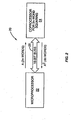
- FIG. 1 shows a circuit to perform long multiplications of lengths N words.
- Circuit 10 comprises a microprocessor 12 and co-processor 14 connected by a 16-bit bus 16.
- the co-processor 14 To perform multiplication of N word values, where N is greater than the maximum value n that can be multiplied by co-processor 14, the co-processor 14 must be invoked numerous times to perform the N word multiplication.
- the co-processor 14 is used to multiply an n word value A with another n word value B, the n words of A and the n words of B have to be output from the microprocessor 12 to the co-processor 14 and then the 2n word result has to be input to the microprocessor 12 from the co-processor 14.
- the bus is one 16-bit word wide, 4n bus transactions would be involved in each n word multiplication.
- the co-processor 14 would likely perform the multiplication in one cycle.
- the bus delay would be in the order of 4n cycles.
- the I/O interface would preferably be organized as a direct memory access (DMA) channel that takes place independently of microprocessor instruction execution so that the microprocessor 12 could process the previous multiplication while the next multiplication was being performed by the co-processor 14.
- DMA direct memory access
- the time to perform an n word multiplication using conventional techniques would, therefore, be (N/n) 2 ⁇ 4n cycles, assuming partial product accumulation could take place in microprocessor 12 in parallel with each n word multiplication.
- multiplication employing the K-O Multiplication Algorithm takes 81 ⁇ 4n cycles; reducing the effort by a factor more than "3".
- Figure 2 illustrates a circuit 20 for squaring 2N word values.
- Circuit 20 comprises a microprocessor 22 and co-processor 24 connected by a bus 26.
- the co-processor 24 squares a 2n word value for similar cost and complexity of a multiplier that multiplies n word values.
- the transfer of the value to be squared from the microprocessor 22 to the co-processor 24 would take the same 2n bus cycles.
- the resulting value is longer, being approximately 4n words.
- one 2n word square requires 6n bus cycles.
- various methods may be used to conceal those values. For example, suppose that the co-processor 24 of Figure 2 implements the squaring routine of Table 7. Further suppose that the co-processor 24 is used to square a secret message string. The secret message string may be broken into its least significant half and its most significant half, which are then squared by recursive calls to the subroutine RECSQR. These values are then broken down into quarters, and so forth. However, there is no requirement to square the most significant half before the least significant half or vice versa. Therefore, it is possible to incorporate a random switch that will randomly choose, separately at each recursion, whether the most or least significant half is squared first.
- the order in which the fragments of the original message string are sent to the co-processor 24 will be unknown.
- a random transposition of the bits of the secret message string will have occurred, rendering it difficult to reconstruct the message string by observing the values sent to the co-processor 24.
- This difficulty is substantially increased if the third recursive call is also randomly ordered with the first two, which can be done at the expense of greater utilization of temporary stack space.
- the routine of Table 7 could be rewritten, in one implementation, to incorporate six different sequences of program steps, each with their own stack indexing, and corresponding to the six different orders in which the three recursive calls could be made.
- a random number from "1" to "6" would select one of the sequences for each recursion. Then, it would not be known whether data sent to the co-processor 24 was a message segment of A1 or A2 or a segment of
- the random ordering of the reduced length squares is preferably determined by an unpredictable, random noise generator. For example, a random signal can be generated by sampling and quantizing a random noise signal whenever a random bit or value is needed.
- the squaring co-processor 24 of Figure 2 may be constructed internally, using the recursive squaring algorithm of Table 7, for example, to express the 2n word square in terms of three n word squares which are added and subtracted as shown in Equation 5. These n word squares, in turn, may be expressed as three n/2 word squares, and so forth, until the wordlength is reached for which a hardware squaring circuit is more compact.
- VHDL Very High Level Design Language
- K-O Multiplication Algorithm can be described in recursive VHDL code such that a circuit block for performing n-by-n word multiplication can be described as interconnections between three circuit blocks that perform n/2 ⁇ n/2 word multiplications.
- recursive VHDL code can be used to describe a 2n word squaring circuit in terms of three interconnected n word squaring circuits, analogous to the program of Table 7.
- the wordlength is recursively reduced to a length for which a specific squaring circuit is more efficient than allowing the recursion to continue to an even shorter wordlength.
- the use of recursive VHDL can reduce the effort in describing a squaring circuit.
- Equation 7 is a recursive definition of an M-bit square in terms of an M-1 bit square, with the addition of an extra term to the M-1 bit square if B M -1 is equal to binary "1".
- FIG. 3 is a squaring circuit 100 implementing the recursive squaring algorithm of Equation 7.
- the recursive squaring circuit 100 comprises an M-1 bit squaring circuit 102, adder circuit 104, and inverter 106.
- Squaring circuit 100 receives an input of M-bits and generates an output of 2M-bits equal to the square of the M-bit input value.
- the least significant M-1 bits of the input are connected to the M-1 bit squaring circuit 102, which provides a 2M-2 bit output.
- the M least significant bits output from squaring circuit 102 become the least significant M output bits of the squaring circuit 100.
- the M-2 most significant bits output from the squaring circuit 102 are input to adder circuit 104.
- the other input to the adder circuit 104 is an M-bit value representing the term 2 M-2 +X M-1 which is equal to the term X M-1 with a "1" added to its most significant bit position B M-2 . If the most significant bit B M-2 is a binary "1”, then adding "1" will result in a binary "0" plus a carry bit, the carry bit being a "1" in the bit position B M . On the other hand, if B M-2 is a binary "0”, then adding "1” generates a "1” at the bit position B M-2 and a "0" carry. Thus, the top two bits of the M-bit term are given by B M-2 and its inverse, which is formed by inverter 106.
- Adder circuit 104 is enabled to add when the most significant bit B M-1 is a binary "1". Otherwise, adder circuit 104 merely outputs the M-2 bits from squaring circuit 102, extended to M-bits by two "0"s in the two most significant bit positions.
- a VHDL compiler is assumed to already contain definitions for adder circuit 104 and inverter 106. When faced with the need to fill in the details of the M-1 bit squaring circuit 102, however, a recursive VHDL compiler will use the definition of the M-bit squarer 100 with M reduced to M-1. Ultimately, a one bit squarer will be required with a two bit output. The two bit output comprises the input bit and "0". The recursion could stop at a higher level, for example, two bits in and four bits out by defining a suitable logic circuit. The two bit squarer does not need adder circuit 104, as the number of bits from the one bit squarer to be added is "0". The adder circuit 104 for the two bit squarer can be replaced with a two bit NAND gate to either pass B 0 and its inverse to the two most significant bits of the four bit output, or else output "0"s.
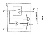
- the two bit squarer 150 comprises an inverter 152 and a pair of NOR gates 154 and 156.
- the designer can describe the additional logic needed to extend a circuit for operating on length N variables to a circuit for operating on length N+1 variables.
- the additional logic is comprised of standard library modules. Then, together with a suitable logic circuit design for a trivial N, such as "1" or "2", the recursive VHDL compiler does the bulk of the design work.
- C N C ⁇ N - 1 + 24 ⁇ N - 2 + 4 ⁇ N + 20 + 1
- Equation 8 C(N) is the number of gate inputs.
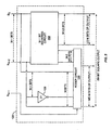
- FIG. 5 illustrates a recursive squaring circuit according to another embodiment of the present invention.
- the squaring circuit 200 of Figure 5 squares an M-bit input and provides a 2M-bit output.
- the squaring circuit 200 comprises three M/2 bit squarers 202, 204, and 206, a subtractor 208, and adders 212 and 214.
- the most significant M/2 bits, denoted A2, of the M-bit input A is squared in M/2 bit squarer 202, while the M/2 least significant bits, denoted A1, are squared in M/2 bit squarer 204.
- Each M/2 bit squarer 202 and 204 produces M-bits of output.
- the M/2 least significant bits of A1 2 are output as the M/2 least significant bits of the final square A 2 .
- Subtractor 208 computes the modulus difference
- the complement +1 may be performed by a carry propagator which has a complexity of about 0.4 adder cells per bit. Thus, the complexity of subtractor 208 is approximately 1.4M/2, which equals 0.7M adder cells. The complexity may be further reduced by employing the technique disclosed in U.S. Patent No. 5,251,164 by Dodson et al .
- M-bit adder 212 adds A1 2 , which is output by squarer 204, and A2 2 , which is output by squarer 202, to produce an M+1 bit result.
- the complexity of adder 212 is, thus, M adder cells.
- the modulus difference output from subtractor 208 is squared by M/2 bit squarer 206 to produce an M-bit square, which is either added to or subtracted from the output of M-bit adder 212.
- Adder/subtractor 210 is controlled by a sign output from subtractor 104. When the sign output by subtractor 208 is a plus, adder/subtractor 210 adds the two values. Conversely, when the sign output by subtractor 208 is a minus, adder/subtractor 210 subtracts the two values.
- the complexity required to successfully negate the M-bits from adder 212 is about 0.25 adder cells per bit, so the complexity of adder/subtractor 210 is approximately 1.25M adder cells.
- the M+1 bits output from adder/subtractor 210 are added to the 3M/2 bits comprised of the M/2 most significant bits of A1 2 and the M-bits of A2 2 output by squarer 202.
- This addition requires M+1 bits of full adder and M/2-1 bits of carry propagation.
- the final adder complexity is thus of the order (M+1)+0.4(M/2-1) full adder cells.
- the bitwise recursion gave a complexity of only 6 adder cells; therefore, the bitwise 4-bit squarer should be used as the starting point for higher order squarers.
- the squaring circuit 200 of Figure 5 has a complexity of 1726, which is a significant reduction on the 2354 adder cells required for bitwise squaring, and the advantage for the squaring circuit 200 as compared to a bitwise squarer improves as the number of bits increase. Based on these calculations, it appears advantageous to define a bitwise recursive 16-bit squarer, which is then employed in sets of three using recursion as disclosed herein to define squarers of longer wordlength. It may be realized from Figure 5 that the technique of recursive VHDL may also be used to describe an M-bit squarer in terms of standard library gates and three M/2-bit squarers.
- the program listing of Table 9 begins by defining the entity "M_BIT_SQUARER" to have I/O ports with M bits of input called XIN indexed 0 to M-1, and 2M bits of output called XOUT indexed 0 to 2M-1 (lines 5-25).
- M is declared to be generic, which means that it is an integer to be supplied later, when a specific "instantiation" of the circuit is invoked by a user of the circuit, for example, by a higher level block incorporating it as a component for a particular value of M.
- VHDL code then continues to describe one possible architecture for an M-bit squarer beginning at line 30.
- the particular architecture described is the bitwise recursive squarer shown in Figure 3 , so this architecture for "M_BIT_SQUARER" is called “BIT_REC_SQR.”
- VHDL allows multiple architectures to be defined for the same logical function, so "M_BIT_SQUARER” could have other, possibly non-recursively defined architectures to realize the circuit. In such case, the user has a choice which configuration to employ in a particular case. Recursively-designed circuits, such as that shown in Figures 3 and 5 , will be more efficient in many circumstances.
- the architecture definition of the M-bit squarer comprises the explicit definition of a 2-bit squarer shown in Figure 4 when it is detected that the value of the generic integer parameter M equals 2. This explicit definition is contained in lines 45-105 of Table 9.
- the 2-bit squarer employs two component types -- an inverter and a 2-input NAND gate.
- the definition of the 2-bit squarer uses one component of type INVERTER connected to two components of type NAND2. The interconnections are specified by which signal names appear in the respective input and output signal lists (argument lists) each time a component is called up.
- BLOCK1 is a block called “ENABLED_ADDER” of length M-2 bits, which is defined in lines 115-150.
- BLOCK2 is a block called “ENABLED_HALF_NADDER”, which logically is a half-adder with inverted sum output.
- BLOCK2 is defined in lines 155-165.
- BLOCK3 is a recursive instantiation of the M-bit adder itself for the generic value of M-1, which is defined in lines 170-190.
- Signal XSQ is used to label the output bits from the M-1 bit squarer.
- the subsequent FOR loop at line 225 connects M bits of the output bits from the M-1 bit squarer to the output bits XOUT.
- the other M-2 bits from the output of the M-1 bit squarer are connected internally to the M-2 bit adder.
- the use of "signals" labeled XSQ when a device calls itself recursively is another potential violation of current VHDL compilers, which cannot distinguish the signals labeled XSQ in the first recursion from signals labeled XSQ in the subsequent recursions. This problem can be fixed in later versions of VHDL compilers for handling recursion by considering "signals" to be created on a work space stack, analogous with the use of stacks in the above-described FORTRAN code.
- bitwise recursive squaring circuit of Figure 3 could, alternatively, be defined by non-recursive VHDL code. Instead of starting with an M-bit squarer and working backward, a VHDL definition could start with a 2-bit squarer and work upward using a "for" loop. Each "for" loop could successively add the additional circuitry to make a 3-bit squarer, a 4-bit squarer, and so forth.
- replacing a backwards recursion from M down to 2 with a forward loop starting at 2 and incrementing upward to M is only possible when the recursive definition of a circuit invokes only one instance of itself.
- the recursive definition of a circuit invokes more than two instances of itself, e.g., three instances needed by the K-O Multiplication Algorithm, then recursion cannot be described by a simple forward iteration.
- one implementation of the inventive design method described herein is to provide a pre-processor for processing recursive VHDL code as exemplified in Table 9 in order to replace it for a specific value of M, with expanded VHDL code containing explicit definitions of each instantiation of a recursively-used circuit block.
- the pre-processor can also resolve the problem of signal name confusion by automatically generating distinct signal names, such as XSQ1, XSQ2, XSQ3 ... and CARRY1, CARRY2, CARRY3 ... etc. for each successive instantiation of the recursively-used block needing its own, separate internal signals.
- the output VHDL code would be compatible with existing, non-recursive VHDL compilers, so could be incorporated in a VHDL circuit design needing a squarer or multiplier or other recursively-designed circuit for a specific value of a generic parameter, such as M in the above example.
- the circuit design would, until recursive compilers are available, comprise the following steps:
- Table 10 shows the definition of a 4-bit squarer generated from the recursive definition of an M-bit squarer.
- FOUR_BIT_SQUARER is 10 port(XIN:in BIT_VECTOR(0 to 3); 15 XOUT:out BIT_VECTOR(0 to 7)); 20 end FOUR_BIT_SQUARER; 25 architecture BIT_REC_SQR_FOUR of FOUR_BIT_SQUARER is 30 component ENABLED_ADDER 35 generic(N:INTEGER); 40 port(A:in BIT_VECTOR(0 to N-1); 45 B:in BIT_VECTOR(0 to N-1); 50 ENABLE:in BIT; 55 C:out BIT_VECTOR(0 to N-1); 60 CARRY:out BIT 65 end component 70 component ENABLED_HALF_NADDER 75 port(BM1,BM
- a pre-processor can be defined that translates recursive VHDL that cannot be compiled by conventional VHDL compilers into non-recursive code that can be used to enable logic circuit designers to avail themselves of the advantages of recursive VHDL in advance of recursive VHDL compilers.
- the use of recursive VHDL as described above can be used for many different types of logic circuits.
- the N-bit adder used in the above example can be defined recursively as an N-1 bit adder, plus an extra adder stage to extend it from N-1 to N-bits. This is an example which, however, can be performed alternatively using a "for" loop.
- the N-bit adder can be defined as a non-recursive VHDL block comprising an "even” type adder cell cascaded with a recursive VHDL block describing an (N-1) bit adder ending with an "odd” type cell.
- This block describes an "odd” cell cascaded with a 1-bit shorter adder ending in an "even” cell, and the adder ending in the even cell recursively calls the adder ending in the "odd” cell.
- the recursion may not be apparent to a standard VHDL compiler as no routine calls itself, but incorrect results are likely to occur unless a true recursive VHDL compiler, or a recursive VHDL pre-processor is used according to the present invention.
- the Kolatgola-Kumar adder may alternatively be defined as a 2N-bit adder comprising an odd/even cell pair cascaded with a (2N-2)-bit adder.
Abstract
Description
- The present invention relates generally to cryptographic accelerators to accelerate cryptographic computation and, more particularly, to a cryptographic accelerator employing recursive algorithms to accelerate multiplication and squaring operations.
- Encryption is the process of disguising intelligible information, called plaintext, to hide its substance from eavesdroppers. Encrypting plaintext produces unintelligible data called cipher text. Decryption is the process of converting ciphered text back to its original plaintext. Using encryption and decryption, two parties can send messages over an insecure channel without revealing the substance of the message to eavesdroppers. A cryptographic algorithm, or cipher, is a mathematical function used in the encryption and decryption of data. A cryptographic algorithm typically works in combination with a key to encrypt and decrypt messages. The key, typically a large random number, controls the encryption of data by the cryptographic algorithm. The same plaintext encrypts to different ciphered text with different keys. In general, it is extremely difficult to recover the plaintext of a message without access to the key, even by an eavesdropper having full knowledge of the cryptographic algorithm.
- One commonly used type of cryptographic algorithm is a public key algorithm. Public key cryptographic algorithms are based on the identity:

- One popular public key algorithm is the RSA Algorithm. The RSA Algorithm enciphers blocks of bits at a time, which may be viewed as a binary number X. The binary number X must have an arithmetic value less than the encryption modulus N. Encryption is performed by raising X to the power of the public key KPUB and reducing it modulo N to produce encrypted ciphertext. The ciphertext may also be viewed as a binary number Y having an arithmetic value less than N. Decryption is performed by raising the binary number Y to the power of the private key KPRIV and reducing the result modulo N.
- Another use of public key algorithms is for signing messages to authenticate the sending party's identity. The sending party may sign a message by encrypting the message with his private key KPRIV. The receiving party can then use the sender's public key KPUB to decrypt the message. If the message is decrypted successfully, only the sending party in possession of the private key KPRIV could have sent that message. This process of authenticating the message by encryption using the sender's private key KPRIV is referred to as signing.
- It is also known to doubly encrypt messages to provide both secure communications and authentication capability. In this case, each party to the communication possesses a public key used for encrypting messages and a private key for decrypting messages. The message is first signed using the sender's private key KPRIV1 and modulus N1 and then encrypted using the recipient's public key KPUB2 and modulus N2. The recipient decrypts the message using the recipient's private key KPRIV2 and modulus N2 to recover the signed message. The signed message is then decrypted using the sender's public key KPUB1 and modulus N1 to obtain the original message. Since the sender is the only person possessing the private key KPRIV1 that can generate the signed message, the sender's identity is authenticated to the recipient.
- Another prior art algorithm that involves exponential operations is the Diffie-Hellman Algorithm. The Diffie-Hellman Algorithm is a key exchange algorithm that allows two parties to agree on a secret key over an insecure channel without divulging the secret key. According to the Diffie-Hellman Algorithm, the parties agree on two, non-secret prime numbers P1 and P2. P1 is typically a large prime number. The security of the system is based on the difficulty of factoring numbers the same size as P1. P2 may be a one-digit prime number. Each party generates a large random number, denoted x and y, respectively. The parties then calculate derived numbers X and Y. The first party computes X using the equation X = P 2 x mod P 1. The second party computes Y using the equation Y = P 1 y mod P 1. The first party transmits X to the second party; the second party transmits Y to the first party. The first party computes the secret key K using the equation K = Yx mod N . The second party computes the secret key K using the equation K = XY mod N . An eavesdropper cannot compute K with knowledge only of P1, P2, X and Y. Therefore, the value K, which was computed independently by the two parties using information exchanged over the insecure channel, may be used by the parties as the secret key for secure communications.
- All of the above-described algorithms involve exponential operations with very large binary numbers. For example, in the RSA Algorithm, the private key KPRIV typically has a length of approximately 2,048 bits. The message block and encryption modulus N are typically in the same order of wordlength. Thus, encryption or decryption with the private key KPRIV involves exponentiating a 2,048 bit message block with a 2,048 bit exponent and reducing the result modulo another 2,048 bit number. These calculations require significant computational power to perform.
- A number of algorithms have been devised to reduce the complexity of cryptographic calculations involving exponentiation or modulo reduction. One algorithm, referred to herein as the Successive Squares Algorithm, is used to raise a first large number to the power of a second large number. A second algorithm, referred to herein as the Modulo Reduction Algorithm, is used to reduce a first large number modulo a second large number.
- The Successive Squares Algorithm is used to raise a bitstring X to a large power Y. In decryption, the bitstring X is the encrypted ciphertext, and the power Y is the decryption key. In encryption, the bitstring X is the plaintext message, and the power Y is the encryption key. The successive squares of the bitstring X are computed and used to multiply an accumulated value Z, depending on the value of a corresponding bit in the power Y. The accumulated value Z is initialized to a starting value of 1. The successive squares are denoted herein as X 1 = X 1,X 2 = X 2,X 3 = X 4,...Xn = X n-1. In the Successive Squares Algorithm, the least significant bit in the power Y, denoted B1, corresponds to the first power of X, the second bit B2 corresponds to the second power of X, the third bit B3 corresponds to the fourth power of X, and so forth until the last bit BL is reached. Each successive square, X1, X2 ...Xn, is used to multiply the accumulated value Z, depending on the value of the corresponding bit BN in the power Y. In particular, the accumulated value Z is multiplied by a successive square when the corresponding bit BN in the power Y is 1. Successive squares corresponding to "0" bits in the power Y do not multiply the accumulated value Z. The Successive Squares Algorithm reduces the number of values that need to be multiplied from 22048 to the order of 2,048 where X and Y are 2,048 bits in length.
- After each multiplication or squaring operation, the accumulated value Z has a wordlength in the order of 4,096 bits. In encryption and decryption, this accumulated value Z is reduced by modulo reduction to a value in the order of 2,048 bits in length. In particular, the result of each squaring operation is reduced modulo the encryption modulus N of wordlength 2,048. This requires subtracting a large number of multiples of N until the value of the accumulated total Z is less than N. The number of multiples of N which have to be subtracted is in the order of 22048 or 10600 which eliminates the possibility of successive subtraction.
- The Modulo Reduction Algorithm is used to reduce a first large number modulo a second large number. According to the Modulo Reduction Algorithm, the approximate reciprocal of N is computed to 2,048 significant bits, ignoring leading zeros after the binary point. Each time a 4,096 bit accumulated value Z is to be reduced modulo N, the approximate number of times T that N would have to be subtracted from Z is calculated using the equation T = Z · 1/N , which is a single long multiplication of Z with the approximate reciprocal of N. The product of T · N is then subtracted from the accumulated value Z, which will reduce the accumulated value Z to within one or two times N of the required result. The reduction is then completed by subtracting the encryption modulus N one or two times more from the accumulated value Z until the remainder is less than N but not negative. This Modulo Reduction Algorithm requires two long multiplications and two subtractions instead of 10600 successive subtractions and is vital to render such calculations possible.
- It is well known in the art that, since squaring is the same as multiplication with two equal arguments, advantage can be taken of the fact that half of the partial products to be summed are the same as the other half, allowing squaring to be performed twice as fast as multiplication. It is also known in the art that the product of two numbers A and B can be obtained from the difference in squares of (A+B) and (A-B).
- In a published paper entitled "Multiplication of Multi Digit Numbers by Automata," by A. Karatsuba and Y. Ofman (Soviet Physics - Docklady 7, page 595-596, 1963), an algorithm, referred to herein as the K-O Multiplication Algorithm, is described for expressing the product of two N-digit numbers in terms of three products of N/2 digit numbers, thereby achieving a reduction to 3/4 of the effort compared with four products of N/2 digit numbers needed conventionally. However, the N/2 multiplications are each, in turn, expressible as three N/4 digit multiplications, and so forth, so that the total reduction of effort is to the value (3/4)log2N, as shown by D.E. Knuth in "The Art of Computer Programming, Vol. 2, Seminumerical Algorithms," (Addison Wesley, Reading, Massachusetts, 1971).
- To achieve the maximum reduction of effort using the K-O Multiplication Algorithm, the recursions should preferably stop at some wordlength where multiplication is more efficiently performed in the conventional manner or by special purpose hardware. Such a stage exists because the effort of multiplication reduces as the square of N while the overhead of the K-O Multiplication Algorithm reduces only linearly, so that at some wordlength, conventional multiplication becomes preferable.
- The
U.S. Patent No. 6,035,317 describes using a co-processor when performing computations according to the method of Karatsuba. - The article "Performance analysis of the parallel Karatsuba multiplication algorithm for distributed memory architectures" by Giovanni Cesari and Roman Maeder published in the Journal of Symbolic Computaiton, vol. 21, no. 4-6, april 1996 (1996-04), presents three parallel implementations of the Karatsuba algorithm for long integer multiplication on a distributed memory architecture and discuss the experimental results obtained on a Paragon computer.
- The K-O Multiplication Algorithm has been used in software applications to perform long multiplication in public key cryptographic algorithms. Implementing the K-O Multiplication Algorithm in software suggests use of recursive programs. Recursion in this field refers to a program subroutine that is allowed to call itself, as opposed to simple iterations or loops. Recursion also includes the case of a first program calling a second program, which in turn calls the first program. In this case, no program calls itself but a compiler that supports recursion is necessary to give correct results when such recursive calls are used. Not all computer languages or implementations of computer programming languages support recursive subroutines.
- Recursively structured hardware circuits for performing calculations are also known. Examples of recursively structured hardware circuits are described in
U.S. Patent No. 6,044,390 to Golnabi et al ;U.S. Patent No. 6,041,340 to Mintzer et al ; and inU.S. Patent No. 5,765,207 to Curran . - It is now common to employ a computer programming-like language known as VHDL to describe logic circuits of a higher complexity as interconnections of logic circuits of a lower complexity, and so forth, until only primitive circuits are required that can be found in an existing library. This hierarchical description of circuits is then translated by the VHDL compiler into a flat interconnection of primitive library elements. Present day VHDL is an example of a language that does not support recursive calls; that is, no circuit block in the hierarchy can include in its description a circuit block which is an instance of itself.
- The present invention relates to a circuit and method for performing squaring operations on long integer values according to the independent claims.
- According to embodiments of the invention, the long integer values, which may represent secret data, can be protected from disclosure by randomly ordering the reduced-length integer values passed from the host processor to the co-processor. The random ordering of the reduced-length integer values results in a random transposition of the bits of the secret data rendering it difficult to reconstruct the secret data by observing the value sent to the co-processor.
-
-
Figure 1 is a block diagram of a circuit to perform multiplications of long integer values. -
Figure 2 is a block diagram of a circuit to square a long integer value. -
Figure 3 is a recursive squaring circuit according to the present invention. -
Figure 4 is a block diagram of a hardware logic circuit to square two bits values. -
Figure 5 is an alternate embodiment of a recursive squaring circuit according to the present invention. - The present invention provides a circuit and method for efficiently performing arithmetic calculations involving long integer values including squaring, multiplication, addition, and modulo reduction. The circuit and method can be used to implement the RSA Algorithm and the Diffie-Hellman Key Exchange Algorithm, both of which require multiplication and squaring of long integers. The circuit comprises a squaring circuit that implements a modified version of the Karatsuba-Ofman (K-O) Multiplication Algorithm. The squaring circuit may also be efficiently used for implementing multiplication of two dissimilar values. Thus, the present invention eliminates the need for a separate multiplication circuit, thereby saving silicon chip area and reducing cost as compared with circuits comprising only a multiplier that is also used for squaring or compared with circuits having both a multiplier and a squarer.
- As indicated above, the squaring device of the present invention is based on the K-O Multiplication Algorithm. One possible expression of the K-O Multiplication Algorithm is as follows:

- The K-O Multiplication Algorithm can, alternately, be expressed as follows:

- Both expressions of the K-O Multiplication Algorithm express a 2k digit multiplication in terms of three approximately k digit multiplications. In
Equations 2 and 3, the values A1 and A2 represent the least significant half and most significant half respectively of a value A to be multiplied. Similarly, the values B1 and B2 represent the least significant half and most significant half respectively of a second value B to be multiplied with A. - In
Equation 2, the multiplication (A1+A2)(B1+B2) is a k+1 digit multiplication due to the possible overflow to one extra bit from the additions. If it is desired to avoid k+1 bit multiplications, the overflow bits may be handled separately, as will be described below. Equation 3 attempts to avoid k+1 digit multiplications by multiplying the differences (A1-A2) and (B1-B2). However, if either A2 is greater than A1 or B2 is greater than B1, one of the factors would be negative. To retain unsigned multiplication, A2-A1 should be used when A2 is greater than A1 and B2-B1 should be used when B2 is greater than B1. If one difference only is reversed, the product (A2-A1)(B1-B2) or (A1-A2)(B2-B1) should be added to (A1·B1)+(A2·B2) instead of subtracted, as will also be demonstrated below. - Table 1 below gives a program listing in FORTRAN for a recursive multiplier implemented in software. The recursive multiplier of Table 1 multiplies quantities of length N=2n
words using Equation 2. The line numbering in the program listing is for reference only.TABLE 1 - RECURSIVE MULTIPLICATION SUBROUTINE IMPLEMENTING EQ. 2 LINE # INSTRUCTION 05 SUBROUTINE RECURM (N,A,B,C,S) 10 INTEGER*2 S(*), A(*), B(*), C(*), BORROW 15 IF(N.EQ.1) THEN 20 CALL MUL16 (A(1),B(1),C) 25 ELSE 30 CALL RECURM (N/2,A,B,C,S,) 35 CALL RECURM (N/2,A(1+N/2),B(1+N/2),C(1+N),S) 40 CALL LONGAD(A,N/2,A(1+N/2),N/2,S, CARRY) 45 CALL LONGAD(B,N/2,B(1+N/2),N/2,S(N/2+2) CARRY) 50 CALL RECURM (N/2,S(1),S(2+N/2),S(N+3),S(2*N+5)) 55 NOVER2=N/2 60 N1=1+NOVER2 65 N2=N+N1+2 70 S(N2+NOVER2)=0 75 S(N2+NOVER2+1)=0 80 IF (S(N1).EQ.1)CALL LONGAD(S(N1+1),NOVER2,S(N2), NOVER2,S(N2)) 85 IF(S(N+2).EQ.1)CALL LONGAD(S(1),N1,S(N2),N1,S(N2)) 90 CALL LONGSB(S(N+3),N+2,C(1),N,S(N+3),BORROW) 95 CALL LONGSB(S(N+3),N+2,C(1+N),N,S,(N+3),BORROW) 100 CALL LONGAD(S(N+3),N+1,C(N1),N2-3,C(N1)) 105 ENDIF 110 RETURN 115 END - In line 5, a subroutine called RECURM is defined which accepts the arguments N, A, B, C, and S. Argument N specifies the wordlength of integer arrays A and B to be multiplied. Arguments A and B provide the starting addresses of two arrays that store the values A and B to be multiplied. Argument C provides the starting address of an array of length 2N(+1 spare location) to receive the product of the multiplication. Argument S provides the starting address of a stack array to be used as a work space.
- At line 15, a test is performed to see if the multiplication required involves only one word variables, which can be efficiently performed by machine hardware. If so, the values A and B to be multiplied, which are stored in integer arrays A and B, are passed in a function call to a multiplication routine denoted MUL16 to perform this short multiplication. The multiplication routine MUL16 performs unsigned integer multiplication between, in this example, 16-bit operands to form a 32-bit result. High level languages, such as FORTRAN, PASCAL, or C, generally perform signed integer multiplication in their high level instructions, which must be circumvented to obtain unsigned multiplication. Table 2 below provides the program listing for an exemplary embodiment of the multiplication routine MUL16 which is included for completeness.
TABLE 2 - MULTIPLICATION SUBROUTINE LINE # INSTRUCTION 05 SUBROUTINE MUL16 (A,B,C) 10 INTEGER*2 A,B,C(8),AA(2),BB(2),CC(2) 15 INTEGER*4 A4,B4, C4 20 EQUIVALENCE (A4, AA), (B4,BB), (C4,CC) 25 AA(2)=A 30 AA(1)=0 35 BB(2)=B 40 BB(1)=0 45 C4=A4*B4 50 C(1)=CC(2) 55 C(2)=CC(1) 60 RETURN 65 END - The multiplication routine of Table 2 could be replaced by a native assembly code routine to perform unsigned multiplication using the machine's hardware directly.
- Returning to Table 1, if the multiplication involves variables greater than one word in length (i.e., N>1), the K-O Multiplication Algorithm is used to reduce the length of the variables to N/2. At line 30, the routine RECURM calls itself to multiply the least significant N/2 words A1 and B1 of values A and B to obtain A1·B1, which represents the least significant N words of the product A·B. The result is stored in result array C. At line 35, the routine RECURM calls itself again to multiply the most significant N/2 words A2 and B2 of values A and B (which start at
element number 1+N/2 of integer arrays A and B) to obtain A2·B2, which represents the most significant N/2 words of the product A·B. The result is stored inarray element 1+N of the result array C. - At lines 40 and 45, the program calls long integer addition routine LONGAD to perform the length N/2 additions A1+A2 and B1+B2 of
Equation 2. The results are placed in the stack S. In particular, the result of the addition A1+A2 is placed in stack elements S(1)...S(N/2), with carry into elements S(1+N/2). The results of the addition B1+B2 are placed in stacked elements S(N/2+2) ... S(N+1), with carry into element S(N+2). Thus, stack elements S(1)...S(N/2) contain the value of A1+A2 less its overflow or carry bit, while stack elements S(N/2+2)...S(N+1) contains the value of B1+B2 less its overflow or carry bit. - At line 50, the sums A1+A2 and B1+B2 minus the overflow or carry bits are multiplied by a third recursive call to the subroutine RECURM to obtain the product (A1+A2)(B1+B2) minus the contribution of the overflow/carry bits. The contributions of the carry bits, if any, are added in lines 80 and 85. Line 80 adds the absolute value of B1+B2 if the carry from the addition A1+A2 was set, and adds the absolute value of A1+A2 if the carry from the addition B1+B2 was set.
- At lines 90 and 95, the already-computed products A1-B1 and A2·B2 are subtracted from the product (A1+A2)(B1+B2) according to
Equation 2. At line 105, the processed value, now (A1+A2)(B1+B2)-A1·B1-A2·B2, is added with a shift of k-bits or N/2 words to the value contained in the result array C to obtain the final 2N word product. - At lines 55 through 75, the program precomputes some indices to simplify addressing. Use of local variables was thereby postponed until all recursive calls of the routine RECURM to itself were made. Otherwise, the values of the local variables would not be preserved through the recursive calls.
- In the third recursive call, at line 50, it may be seen that the starting address S(2N+5) was passed to the routine LONGAD as the starting address of the stack array S. The address S(2N+5) addresses a place in the stack array beyond all the stack positions currently used to hold temporary results, so that the recursive call will not corrupt already-computed intermediate results whose use are later required. Moreover, the address S(2N+5) is beyond the position in the stack array S that will be used to receive the product of the recursive call.
- In the routine of Table 1, there is a certain overhead involved in avoiding k+1 bit multiplications. This overhead could be avoided if the recursive routine was written to perform multiplications of arrays of any length, including odd lengths and powers other than 2, but this involves different overheads. Instead, the second form of the K-O Multiplication Algorithm shown in Equation 3 may be used.
- Table 3 below is a program listing of a recursive multiplier implementing the form of the K-O Multiplication Algorithm shown in Equation 3.
TABLE 3 - ALTERNATE RECURSIVE MULTIPLICATION SUBROUTINE LINE # LABEL INSTRUCTION 05 SUBROUTINE RECURM (N,A,B,C,S) 10 INTEGER*2 S(*), A(*), B(*), C(*), BORROW, LARGER 15 INTEGER *4 N 20 IF (N.EQ.1) THEN 25 CALL MUL16 (A(1), B(1), C) 30 ELSE 35 CALL RECURM (N/2,A,B,C,S) 40 CALL RECURM (N/2,A(1+N/2),B(1+N/2),C(1+N),S) 45 IF (LARGER (A,A(1+N/2), N/2))1,2,3 50 1 CALL LONGSB (A(1+N/2),N/2,A,N/2,S,BORROW) 55 IF (LARGER (B,B(1+N/2),N/2))4,2,5 60 4 CALL LONGSB (B(1+N/2),N/2,B,N/2,S(1+N/2), BORROW) 65 GO TO 8 70 5 CALL LONGSB (B,N/2,B(1+N/2),N/2,S(1+N/2), BORROW) 75 GO TO 9 80 3 CALL LONGSB (A,N/2,A(1+N/2),N/2,S, BORROW) 85 IF (LARGER (B,B(1+N/2),N/2))6,2,7 90 6 CALL LONGSB (B(1+N/2),N/2,B,N/2,S(1+N/2), BORROW) 95 9 CALL RECURM (N/2,S(1),S(1+N/2),S(N+2),S(2*N+4)) 100 CALL LONGAD (C,N,C(1+N),N,S) 105 CALL LONGAD (S,N+1,S(N+2),N,S) 110 GO TO 10 115 7 CALL LONGSB (B,N/2,B(1+N/2),N/2,S(1+N/2), BORROW) 120 8 CALL RECURM (N/2,S(1),S(1+N/2),S(N+2),S(2*N+4)) 125 CALL LONGAD (C,N,C(1+N),N,S) 130 CALL LONGSB (S,N+1,S(N+2),N,S) 135 GO TO 10 140 2 CALL LONGAD (C,N,C(1+N),N,S) 145 10 CALL LONGAD (C(1+N/2),N+N/2,S,N+1,C(1+N/2)) 150 ENDIF 155 RETURN 160 END - At line 05, the subroutine RECURM and its arguments are defined as previously described. At
line 20, the program performs a test to determine whether the multiplication can be performed in hardware by looking at the wordlength of the values A and B to be multiplied. If the values A and B have a wordlength of 1, the values to be multiplied are passed in a function call to the multiplication routine MUL16. If the values A and B have a wordlength greater than 1, the program makes recursive calls at lines 35 and 40 to compute A1·B1 and A2·B2, as previously described. At line 35, the program RECURM calls itself to perform N/2 word multiplication between the least significant N/2 words A1 and B1 of values A and B to obtain the least significant N/2 words of the product A·B, which is stored in result array C. At line 40, the program RECURM calls itself a second time to perform N/2 word multiplication between the most significant N/2 words A2 and B2 of values A and B to obtain the most significant N/2 words of the product A·B, which is stored in array element C(1+N) of the result array C. At line 45, the relative values of A1 and A2 are compared by an integer function denoted as LARGER. If A1 =A2, the product (A1-A2)(B1-B2) will be 0 and a jump is made to the line denoted by label 2 (line 140), bypassing the steps of computing and multiplying B1-B2. At line 140, the already-computed products A1·B1 and A2·B2 are added together and the result is then added to the result array C with a shift of N/2 words at line 145, completing the 2N word product. - If, at line 45, the function LARGER indicates that A1 is greater than A2, the program jumps to label 3 (line 80) to compute the difference A1-A2. At line 85, the program compares B1 and B2. If B1 and B2 are equal, execution jumps to label 2 (line 140). As previously described, the already-computed products A1·B1 and A2·B2 are added at line 140 and the result is then added to the result array C with a shift of N/2 words at line 145 to arrive at the final 2N word product.
- If, at line 85, the function LARGER indicates that B1 is greater than B2, execution jumps to label 7 (line 115). At line 115, the program computes the difference B1-B2. At line 120, the program computes the product of the differences A1-A2 and B1-B2. At line 125, the program computes the sum of the products A1·B1 and A2·B2. At line 130, the product computed at line 120 is subtracted from the sum computed at line 125, which is represented by the expression A1·B1+A2·B2-(A1-A2)(B1-B2). This result is then added to the result array C with a shift of N/2 words at line 145 to compute the final 2N word product.
- If, at line 85, the function LARGER indicates that B2 is greater than B1, execution jumps to Label 6 (line 90) where the difference B2-B1 is computed. At line 95, the program calls itself to compute the product of the differences A1-A2 and B2-B1. At
line 100, the sum of the products A1·B1 and A2·B2 is computed. Then, at line 105, the product computed in line 95 is added to the sum computed inline 100. The resulting value is represented by the expression A1·B1+A2·B2+(A1-A2)(B2-B1). This result is then added to the result array C at line 145 to compute the final 2N word product. - If, at line 45, the function LARGER indicates that A2 is greater than A1, the program jumps to label 1 (line 50). At line 50, the program computes the difference A2-A1. At line 55, the program compares B1 and B2. If B1 and B2 are equal, execution jumps to label 2 (line 140). At line 140, the already-computed products A1·B1 and A2·B2 are added. The result is then added to the result array C with a shift of N/2 words at line 145 to arrive at the final 2N word product.
- If, at line 55, the function LARGER indicates that B1 is greater than B2, execution jumps to label 5 (line 70) where the difference B1-B2 is computed. At line 75, a jump is made to label 9 (line 95) where the product of the differences A2-A1 and B1-B2 is computed. At
line 100, the sum of the products A1·B1 and A2·B2 is computed. Then, at line 105, the product computed in line 95 is added to the sum computed inline 100. The resulting value is represented by the expression A1·B1+A2·B2+(A2-A1)(B1-B2). This result is then added to the result array C at line 145 to compute the final 2N word product. - If, at line 55, the function LARGER indicates that B2 is greater than B1, execution jumps to label 4 (line 60) where the difference B2-B1 is computed. At line 65, the program jumps to label 8 (line 120). At line 120, the program makes a recursive call to compute the product of the differences A2-A1 and B2-B1. At line 125, the program computes the sum of the products A1·B1 by and A2·B2. At line 130, the program adds the product computed in line 120 to the sum computed in line 125, which is represented by the expression A1·B1+A2·B2-(A2-A1)(B2-B1). At line 135, program execution jumps to label 10 (line 145). This result is then added to the result array C at line 145 to compute the final 2N word product.
- Table 4 below is a program listing for the function LARGER which is used in the routine of Table 3.
TABLE 4 - FUNCTION TO COMPARE TWO VALUES LINE # LABEL INSTRUCTION 05 INTEGER*2 FUNCTION LARGER (X,Y,N) 10 INTEGER*2 X(*),Y(*),X16(2),Y16(2) 15 INTEGER*4 X32, Y32 20 EQUIVALENCE (X32,X16),(Y32,Y16) 25 X16(1)=0 30 Y16(1)=0 35 DO 1 I=N,1,-1 40 X16(2)=X(I) 45 Y16(2)=Y(I) 50 IF (X32.NE.Y32) GO TO 99 55 1 CONTINUE 60 LARGER=0 65 RETURN 70 99 IF (X32.GT.Y32) THEN 75 LARGER=1 80 ELSE 85 LARGER=-1 90 ENDIF 95 RETURN 100 END - The subroutine LARGER compares two values (e.g., A1 and A2), starting with the most significant word. If the most significant word of A1 is greater than that of A2, the comparison can stop there, otherwise the next most significant words must be compared. If all the words compared are equal, the result LARGER =0 is returned, signifying that A1=A2. By comparing most significant words first, the result is, in the majority of cases, obtained with only a one-word comparison, which is much quicker than comparing A1 and A2 by performing a long subtraction followed by a long negation if the result was negative to obtain the absolute value of A1-A2. The same procedure is used to compare B1 and B2.
- In the exemplary LARGER routine, the 16-bit values are cast into 32-bit form with a most significant word of zero, in order to compare unsigned values. This high-level language routine could be replaced by an assembly code routine to gain access to the machine's native unsigned integer comparison instructions.
-
Equation 4 below is one expression for an efficient recursive long integer squaring algorithm.
- Alternatively, the recursive long integer squaring algorithm may be expressed as follows:

- In
Equations 4 and 5, A1 is the least significant part of A and A2 is the most significant part of A. In the first version of the recursive long integer squaring algorithm, the square (A1+A2)2 is a k+1 squaring operation due to the possible overflow to one extra bit of the addition A1 +A2. The second version of the recursive long integer squaring algorithm attempts to avoid this problem by squaring the difference of A1 and A2. - Table 5 below is a FORTRAN program listing implementing the first version of the recursive long integer squaring algorithm exemplified by
Equation 4.TABLE 5 - RECURSIVE SQUARING SUBROUTINE LINE # INSTRUCTION 05 SUBROUTINE RECSQR (N,A,ASQ,S) 10 INTEGER*2 S(*), A(*), ASQ(*), A16(2), BORROW 15 INTEGER*4 N,A32 20 EQUIVALENCE (32, A16) 25 IF(N.EQ.1)THEN 30 A16(2)=A(1) 35 A16(1)=0 40 A32=A32**2 45 ASQ(1)=A26(2) 50 ASQ(2=A16(1) 55 ELSE 60 CALL RECSQR (N/2,A,ASQ,S) 65 CALL RECSQR (N/2,A(1+N/2), ASQ (N+1),S) 70 CALL LONGAD (A,N/2,A(1+n/2),N/2,S) 75 CALL RECSQR (N/2),S(1),S(2+N/2),S(N+N/2+3)) 80 NOVER2=N/2 85 N1=NOVER2+1 90 N2=N1+1 95 NP2=N+2 100 S(N[2+NOVER2)=0 105 S(N[2+N1)=0 110 IF (S(N1).EQ.1) THEN 115 CALL LONGAD (S(N[2),NOVER2,S(1),NOVER2,S(NP2)) 120 CALL LONGAD (S(N[2),N1,S(1),N1,S(N[2)) 125 ENDIF 130 CALL LONGSB (S(N2),N[2,ASQ(1),N,S(N2),BORROW) 135 CALL LONGSB(S(N2),NP2,ASQ(N+1),N,S(N2),BORROW) 140 CALL LONGAD (S(N2),N+1,ASQ(N1),N+NOVER2,ASQ(N1)) 145 RETURN 150 ENDIF 155 END - At line 05, the subroutine RECSQR is defined with arguments N, A, ASQ, and S. The argument N is the wordlength of the value A to be squared. Argument A is the starting address of an array containing the value A to be squared. Argument ASQ is the starting address of an array to receive the result of the squaring operation. Argument S is the starting address of a stack to be used as a work space.
- At line 25, the program performs a test to determine if the value A to be squared is a one-word value, in which case, the squaring operation can be performed conventionally in lines 30-50. If the value A to be squared is greater than one word, the program calls itself at line 60 and 65 to compute the squares A12 and A22. In line 60, the program squares A1, which represents the least significant N/2 words of A and places the result in the result array ASQ. In line 65, the program squares A2, which represents the N/2 most significant words of A and places the result in array element ASQ (N+1) of the result array ASQ. At line 70, the sum A1+A2 is computed by the long addition routine LONGAD. The N/2 word result is placed in the stack S in elements S(1) to S(N/2), with a carry or overflow bit in S(1+N/2). At line 75, a third recursive call is made to square the sum A1+A2, minus the overflow bit. If the overflow bit is detected to be set in line 105, the square is corrected in lines 110 and 115. In line 110, the sum A1+A2 is added to the most significant end of the square (A1+A2)2. At line 115, the absolute value of (A1+A2) is added to the most significant end of the square (A1+A2)2. The two already-computed squares A12 and A22 are then subtracted at lines 130 and 135, respectively, from the square (A1+A2)2. The result, represented by the expression (A1+A2)2-A12-A22, is then added to the result array ASQ at line 140 with a shift of k-bits or N/2 words, thus completing the 2N word square.
- In the routine shown in Table 5, two extra calls to the LONGAD function are incurred when A1+A2 overflows to a (k+1)th bit. This overflow could be avoided by writing a routine to square an N word value where N is not constrained to be a power of 2. However, there are other overheads which are then encountered. Instead, the second recursive long integer squaring algorithm exemplified in Equation 5 can be used.
- Table 6 below is a FORTRAN program listing to perform the second version of the recursive long integer squaring algorithm shown in Equation 5.
TABLE 6 - ALTERNATE RECURSIVE SQUARING SUBROUTINE LINE # LABEL INSTRUCTION 05 SUBROUTINE RECSQR (N,A,ASQ,S) 10 INTEGER*2 S(*), A(*), ASQ(*), A16(2), BORROW 15 INTEGER*4 N,A32 20 EQUIVALENCE (A32,A16) 25 IF (N.EQ.1) THEN 30 A16(2)=A(1) 35 A16(1)=0 40 A32=A32**2 45 ASQ(1)=A16(2) 50 ASQ(2)=A26(1) 55 ELSE 60 CALL RECSQR (N/2,A,ASQ,S) 65 CALL RECSQR (N/2,A(1+N/2),ASQ(N+2),S) 70 CALL LONGAD (ASQ,N,ASQ(1+N),N,S) 75 IF (LARGER(A,A(1+N/2),N/2))1,2,3 80 1 CALL LONGSB (A(1+N/2),N/2,A,N/2,S(N+2), BORROW) 85 GO TO 4 90 3 CALL LONGSB (A,N/2,A(1+N/2),N/2,S(N+2), BORROW) 95 4 CALL RECSQR (N/2,S(N+2),S(N+n/2+2),S(2*N+N/2+3)) 100 CALL LONGSB (S,N+1,S(N+N/2+2),N,S, BORROW) 105 2 CALL LONGAD (ASQ(1+N/2),N+N/2,S,N+1,ASQ(1+N/2)) 110 ENDIF 115 RETURN 120 END - In line 05, the subroutine RECSQR with arguments N, A, ASQ, and S is defined as previously described. At line 25, the program performs a test to determine whether the value A to be squared is a one-word value. If so, the square is performed conventionally in lines 30-50. Otherwise, the program calls itself in lines 60 and 65 to compute, respectively, A12 and A22. In line 60, the program computes A12 and stores the result in the result array ASQ. In line 65, the program computes A22 and stores the result in element ASQ (N+1) of the result array ASQ. The squares are then added at line 70 by calling the LONGAD routine and the sum A12+A22 is placed in the stack S at S(1)... S(N) with a possible overflow or carry bit in S(N+1).
- At line 75, the values A1 and A2 are compared. If A1=A2, program execution jumps to label 2 (line 105), bypassing the unnecessary step of computing A1-A2. At line 105, the already-computed sum of the squares A12 and A22 is added to the result array ASQ with a left shift of N/2 words to obtain the final 2N word sequence.
- If the function LARGER indicates that A1 is greater than A2 at line at line 75, the program jumps to label 3 (line 90) where the difference A1-A2 is computed. If instead, the function LARGER indicates that A2 is greater than A1, the program proceeds at label 1 (line 80) to compute the difference A2-A1. After computing the difference A1-A2 in line 90 or A2-A1 in line 80, the program execution continues at label (line 95) with a recursive call to itself to compute the square of the difference A1-A2 or A2-A1. At
line 100, the square of the difference between A1 and A2 is subtracted from the sum of the squares A12 and A22. This result is represented by the expression A12+A22-(A1-A2)2. This result is then added at line 105 to the result array ASQ with a left shift of N/2 words to complete the 2N word square. - In the third recursive call at line 95, the stack address S(2·N+N/2+3) is passed to the routine as the last argument to be used for work space. This address space is beyond the area of the stack used to hold the intermediate results, including the result of the third recursive call itself, which is placed in stack elements S(N+N/2+2)... S(2·N+N/2+1).
- In all of the routines described above, the overhead in computing indices is reduced when smart, optimizing compilers are used, which replace integer division or multiplication by 2 with shifts, and avoid computing the same value more than once in the same statement. This overhead is also of less significance at the stage of recursion where longer squares and adds or subtracts are being performed, but is of significance at the recursion stage where single word squares are performed. Thus, it is desirable to perform these lower stages of recursion by specially-designed hardware up to the longest wordlengths for which the hardware complexity is affordable in a given application. The software recursions are then used only for longer wordlengths.
- The subroutines shown in Tables 5 and 6 can be modified to utilize external hardware. Table 7 below is a modified version of the program shown in Table 6 implementing the second version of the recursive long integer squaring algorithm.
TABLE 7 - RECURSIVE SQUARING SUBROUTINE WITH HARDWARE CALL LINE # LABEL INSTRUCTION 05 SUBROUTINE RECSQR(N,A,ASQ,S) 10 INTEGER*2 S(*),A(*),ASQ(*),A16(2),BORROW 15 INTEGER*4 N,A32 20 EQUIVALENCE (A32,A16) 25 IF(N.LE.8)THEN 30 CALL HARDWARE(A,ASQ) 35 ELSE 40 CALL RECSQR(N/2,A,ASQ,S) 45 CALL RECSQR(N/2,A(1+N/2),ASQ(N+1),S) 50 CALL LONGAD(ASQ,N,ASQ(1+N),N,S) 55 IF(LARGER(A,A(1+N/2),N/2))1,2,3 60 1 CALL LONGSB(A(1+N/2),N/2,A,N/2,S(N+2),BORROW) 65 GO TO 4 70 3 CALL LONGSB(A,N/2,A(1+N/2),N/2,S(N+2),BORROW) 75 4 CALL RECSQR(N/2,S(N+2),S(N+N/2+2),S(2*N+N/2+3)) 80 CALL LONGSB(S,N+1,S(N+N/2+2),N,S,BORROW) 85 2 CALL LONGAD(ASQ(1+N/2),N+N/2,S,N+1,ASQ(1+N/2)) 90 ENDIF 95 RETURN 100 END - In this modified version of the recursive squaring routine, the wordlength test at line 25 is modified. In particular, the modified subroutine performs a test at line 25 to determine whether the wordlength of the value A being squared is less than or equal to the maximum wordlength that can be handled by the hardware. In the given example, the maximum wordlength that can be handled by the hardware is eight words. If the wordlength of A is less than or equal to 8, the program calls a hardware routine denoted HARDWARE to perform squaring of the value A. Alternatively, an efficient assembly code routine for computing eight word squares could be called in line 30. Otherwise, if N is greater than the maximum wordlength that can be handled by the hardware, software recursion is performed as previously described. Lines 40-100 in the subroutine shown in Table 7 are identical to line 60-120 of the subroutine shown in Table 6.
- Since many squares have to be computed to raise a long integer to a long power, hardware may be employed to assist the software routines to accelerate the computation of squares, as is exemplified in Table 7. The squaring hardware could perform squares of the longest affordable wordlength. Since a squarer is simpler than a multiplier, squarers of a longer wordlength than a multiplier of equivalent complexity can be constructed. If a hardware multiplier also has to be provided, the affordable chip area would have to be shared between a multiplier and a squarer of shorter wordlength than a squarer alone. Therefore, according to the present invention, hardware is provided to perform squaring with the longest possible wordlength, and the squarer is used to accelerate multiplication by using the difference between two squares technique for multiplying, which is illustrated by the program listing in Table 8.
TABLE 8 - MULTIPLICATION SUBROUTINE USING DIFFERENCE OF SQUARES TECHNIQUE LINE # LABEL INSTRUCTION 05 SUBROUTINE RECMUL (N,X,Y,Z,STACK) 10 INTEGER*2 X(*),Y(*),Z(*),STACK(*),BORROW,CARRY,LARGER 15 N2=2*N 20 N1=N2+1 25 N2P1=2*N+2 30 IF(LARGER(X,Y,N))3,2,1 35 1 CALL LONGAD(X,N,Y,N,STACK) 40 CALL LONGSB(X,N,Y,N,STACK(N+2),BORROW) 45 CALL LSHFTR(STACK,N2P1-1,CARRY) 50 CALL RECSQR(N,STACK(1),Z,STACK(N2P1)) 55 CALL RECSQR(N,STACK(N+2),STACK(N2P1),STACK(N2P1+N1)) 60 CALL LONGSB(Z,N2,STACK(N2P1),N2,Z,BORROW) 65 IF(CARRY.NE.0)CALL LONGAD(Z,N2,Y,N,Z) 70 RETURN 75 2 CALL RECSQR(N,X,Z,STACK) 80 RETURN 85 3 CALL LONGAD(X,N,Y,N,STACK) 90 CALL LONGSB(Y,N,X,N,STACK(N+2),BORROW) 95 CALL LSHFTR(STACK,N2P1-1,CARRY) 100 CALL RECSQR(N,STACK(1),Z,STACK(N2P1)) 105 CALL RECSQR(N,STACK(N+2),STACK(N2P1),STACK(N2P1+N1)) 110 CALL LONGSB(Z,N2,STACK(N2P1),N2,Z,BORROW) 115 IF(CARRY.NE.0)CALL LONGAD(Z,N2,X,N,Z) 120 RETURN 125 END - Table 8 is a program listing in FORTRAN for a subroutine denoted RECMUL that performs multiplication using the difference between two squares technique. The subroutine is defined at line 05 which accepts the arguments N, X, Y, Z, and STACK. Argument N specifies the wordlength of the values X and Y to be multiplied. Arguments X and Y give the starting addresses for two integer arrays that store the values X and Y. Argument Z provides the starting address of a 2N word array to receive the result of the multiplication. The argument STACK provides the starting address of a work space stack to store temporary results.
- At line 30, the values X and Y are compared to determine which is larger. If the stored values are equal, the desired product is simply X2 or Y2, which is computed by jumping to statement label 2 (line 75). At line 75, the program calls the recursive square subroutine shown in Table 6 or 7 and returns the result at line 80.
- If, at line 30, the function LARGER determines that X is greater than Y, then execution proceeds at label 1 (line 35). At line 35, the sum of X and Y is computed by the LONGAD subroutine. The difference X-Y is then computed at line 40 by the LONGSB subroutine. The sum X+Y is stored in stack elements S(1) to S(N) with a possible overflow bit in stacks element (N+1). The difference X-Y is stored in stack elements S(N+2) to S(2N+1). At line 45, the entire array stack S(1) to S(2N+1) is then right shifted one bit by long right shift subroutine LSHFTR to form (X+Y)/2 and (X-Y)/2. This shifting operation incorporates the overflow bit from X+Y but drops the least significant bit. The recursive squares routine of Tables 6 or 7 is then called at lines 50 and 55 to compute the squares of (X+Y)/2 and (X-Y)/2, respectively. The first square computed at line 50 is added to the result array Z. The second square computed at line 55 is placed in the array STACK. At line 60, the second square is subtracted from the first square and the result is placed in the result array Z.
- At line 65, a test is performed to determine whether the dropped least significant bit is "0". If X+Y and X-Y are both even, the dropped least significant bit is 0 and can, therefore, be forgotten. In this case, the result stored in array Z is returned at line 70. On the other hand, if X+Y and X-Y are both odd, the dropped least significant bit is "1". In this case, the difference of the squares computed in line 60 will be short of the desired product XY by the value of Y. Consequently, if it is determined at line 65 that the dropped least significant bit is a "1", Y must be added to complete the desired product.
- If at line 30, the subroutine LARGER determines that Y is larger than X, program execution jumps to statement label 3 (line 85). At line 85, the sum X+Y is computed by the subroutine LONGAD and, at line 90, the difference Y-X is computed by the subroutine LONGSB. The sum X+Y is placed in stack elements S(1)...S(N) with a possible overflow bit in stack element S(N+1). The difference Y-X is placed in stack elements S(N+2)...S(2N+1). The entire array stack S(1)...S(2N+1) is then right shifted one bit by long right shift subroutine LSHFTR to form (X+Y)/2 and (Y-X)/2 which includes the overflow bit from X+Y but drops the least significant bit. The recursive squares routine of Table 6 or 7 is then called in
lines 100 and 105 to form the squares of (X+Y)/2 and (Y-X)/2, respectively. At line 110, the difference of the two squares is computed and then a test is performed at line 115 to determine whether the dropped least significant bit affects the final product. If the least significant bit is a "0", the least significant bit can be ignored. If, on the other hand, the least significant bit is a "1", the long integer addition subroutine LONGAD is called to add the value of X to the result array Z to obtain the final product. - The subroutine in Table 8 is not recursive but calls the recursive squares subroutine of Table 6 or 7. Thus, variables local to RECMUL are not destroyed by the call to REQSQR. Moreover, the subroutine RECMUL executes only once with N equal to the whole variable length, so addressing overhead is insignificant. The efficiency of multiplication using the difference between two squares is, thus, almost entirely governed by the efficiency of the squaring routine RECSQR.
- Referring now to the drawings,
Figure 1 shows a circuit to perform long multiplications of lengths N words.Circuit 10 comprises amicroprocessor 12 andco-processor 14 connected by a 16-bit bus 16. To perform multiplication of N word values, where N is greater than the maximum value n that can be multiplied byco-processor 14, the co-processor 14 must be invoked numerous times to perform the N word multiplication. Each time theco-processor 14 is used to multiply an n word value A with another n word value B, the n words of A and the n words of B have to be output from themicroprocessor 12 to theco-processor 14 and then the 2n word result has to be input to themicroprocessor 12 from theco-processor 14. Assuming that the bus is one 16-bit word wide, 4n bus transactions would be involved in each n word multiplication. The co-processor 14 would likely perform the multiplication in one cycle. The bus delay would be in the order of 4n cycles. - The I/O interface would preferably be organized as a direct memory access (DMA) channel that takes place independently of microprocessor instruction execution so that the
microprocessor 12 could process the previous multiplication while the next multiplication was being performed by theco-processor 14. The time to perform an n word multiplication using conventional techniques would, therefore, be (N/n)2·4n cycles, assuming partial product accumulation could take place inmicroprocessor 12 in parallel with each n word multiplication. Using the K-O Multiplication Algorithm, however, the N word multiplication can be completed in 3log2 (N/n) · 4n cycles. For n=8 and N=128, for example, the conventional multiplication with the aid ofco-processor 14 takes 256·4n cycles. In contrast, multiplication employing the K-O Multiplication Algorithm takes 81·4n cycles; reducing the effort by a factor more than "3". -
Figure 2 illustrates acircuit 20 for squaring 2N word values.Circuit 20 comprises amicroprocessor 22 andco-processor 24 connected by abus 26. The co-processor 24 squares a 2n word value for similar cost and complexity of a multiplier that multiplies n word values. The transfer of the value to be squared from themicroprocessor 22 to the co-processor 24 would take the same 2n bus cycles. The resulting value, however, is longer, being approximately 4n words. Thus, one 2n word square requires 6n bus cycles. - To perform a 2n word square using the n-by-n word multiplier of
Figure 1 would, in contrast, require 16n bus cycles using conventional multiplication, or 12n cycles using K-O Multiplication. Thus, computing a long square using thecircuit 20 shown inFigure 2 is faster than computing a long square using thecircuit 10 ofFigure 1 for the same co-processor chip complexity. Since public key algorithms involve many squaring operations, it is advantageous to use the circuit architecture ofFigure 2 rather thanFigure 1 in cryptographic calculations. - Public key algorithms also require many multiplications. Using the circuit architecture of
Figure 2 , a multiplication of two 2n words is performed by computing two 2n word squares and taking the difference, as shown in Table 8. The two 2n word squares require 12n bus transactions. To compute a 2n by 2n word product using the circuit architecture ofFigure1 and the K-O Multiplication Algorithm requires the computation of three n·n products, each of which takes 4n buss transactions for a total of 12n transactions. Therefore, there is no disadvantage in terms of I/O delay between the circuit architectures ofFigures 1 and2 for multiplication. Therefore, utilizing a co-processor 24 optimized for squaring as shown inFigure 2 improves the efficiency for computing squares without reducing the efficiency for performing multiplications. - If it is desired to protect the values that are passed to the co-processor 24, various methods may be used to conceal those values. For example, suppose that the
co-processor 24 ofFigure 2 implements the squaring routine of Table 7. Further suppose that the co-processor 24 is used to square a secret message string. The secret message string may be broken into its least significant half and its most significant half, which are then squared by recursive calls to the subroutine RECSQR. These values are then broken down into quarters, and so forth. However, there is no requirement to square the most significant half before the least significant half or vice versa. Therefore, it is possible to incorporate a random switch that will randomly choose, separately at each recursion, whether the most or least significant half is squared first. When the recursion eventually reaches a length that can be performed by theco-processor 24, the order in which the fragments of the original message string are sent to the co-processor 24 will be unknown. Thus, a random transposition of the bits of the secret message string will have occurred, rendering it difficult to reconstruct the message string by observing the values sent to theco-processor 24. This difficulty is substantially increased if the third recursive call is also randomly ordered with the first two, which can be done at the expense of greater utilization of temporary stack space. For example, the routine of Table 7 could be rewritten, in one implementation, to incorporate six different sequences of program steps, each with their own stack indexing, and corresponding to the six different orders in which the three recursive calls could be made. A random number from "1" to "6" would select one of the sequences for each recursion. Then, it would not be known whether data sent to the co-processor 24 was a message segment of A1 or A2 or a segment of |A1-A2|. Thus, the task of determining the secret message string from asecure microprocessor 22 to aninsecure co-processor 24 can be rendered much more difficult. The random ordering of the reduced length squares is preferably determined by an unpredictable, random noise generator. For example, a random signal can be generated by sampling and quantizing a random noise signal whenever a random bit or value is needed. - The squaring
co-processor 24 ofFigure 2 may be constructed internally, using the recursive squaring algorithm of Table 7, for example, to express the 2n word square in terms of three n word squares which are added and subtracted as shown in Equation 5. These n word squares, in turn, may be expressed as three n/2 word squares, and so forth, until the wordlength is reached for which a hardware squaring circuit is more compact. - It is commonplace to design logic circuits using a software tool called Very High Level Design Language or VHDL. VHDL allows circuits to be defined as a hierarchy of interconnections between lower level circuit blocks to form higher level circuit blocks. However, VHDL using recursive definition of logic circuits may provide an even greater reduction in the design effort required. Recursive algorithms, such as the K-O Multiplication Algorithm, can be described in recursive VHDL code such that a circuit block for performing n-by-n word multiplication can be described as interconnections between three circuit blocks that perform n/2·n/2 word multiplications. Recursive VHDL code would then rely on itself to fill in the definitions of the n/2-by-n/2 word multipliers in terms of n/4-by-n/4 word multipliers, and so forth. Ultimately, a specific design must be provided for a multiplier at the wordlength where a specific design is more efficient than allowing the recursion to continue to an even shorter wordlength.
- Likewise, recursive VHDL code can be used to describe a 2n word squaring circuit in terms of three interconnected n word squaring circuits, analogous to the program of Table 7. Ultimately, the wordlength is recursively reduced to a length for which a specific squaring circuit is more efficient than allowing the recursion to continue to an even shorter wordlength. Even then, the use of recursive VHDL can reduce the effort in describing a squaring circuit. For example, an M-bit value to be squared may be expressed as follows:

- The square of XM can then be expressed as follows:

- Equation 7 is a recursive definition of an M-bit square in terms of an M-1 bit square, with the addition of an extra term to the M-1 bit square if BM-1 is equal to binary "1".
-
Figure 3 is a squaringcircuit 100 implementing the recursive squaring algorithm of Equation 7. Therecursive squaring circuit 100 comprises an M-1bit squaring circuit 102,adder circuit 104, andinverter 106. Squaringcircuit 100 receives an input of M-bits and generates an output of 2M-bits equal to the square of the M-bit input value. The least significant M-1 bits of the input are connected to the M-1bit squaring circuit 102, which provides a 2M-2 bit output. The M least significant bits output from squaringcircuit 102 become the least significant M output bits of the squaringcircuit 100. The M-2 most significant bits output from the squaringcircuit 102 are input to addercircuit 104. The other input to theadder circuit 104 is an M-bit value representing theterm 2M-2+XM-1 which is equal to the term XM-1 with a "1" added to its most significant bit position BM-2. If the most significant bit BM-2 is a binary "1", then adding "1" will result in a binary "0" plus a carry bit, the carry bit being a "1" in the bit position BM. On the other hand, if BM-2 is a binary "0", then adding "1" generates a "1" at the bit position BM-2 and a "0" carry. Thus, the top two bits of the M-bit term are given by BM-2 and its inverse, which is formed byinverter 106.Adder circuit 104 is enabled to add when the most significant bit BM-1 is a binary "1". Otherwise,adder circuit 104 merely outputs the M-2 bits from squaringcircuit 102, extended to M-bits by two "0"s in the two most significant bit positions. - A VHDL compiler is assumed to already contain definitions for
adder circuit 104 andinverter 106. When faced with the need to fill in the details of the M-1bit squaring circuit 102, however, a recursive VHDL compiler will use the definition of the M-bit squarer 100 with M reduced to M-1. Ultimately, a one bit squarer will be required with a two bit output. The two bit output comprises the input bit and "0". The recursion could stop at a higher level, for example, two bits in and four bits out by defining a suitable logic circuit. The two bit squarer does not needadder circuit 104, as the number of bits from the one bit squarer to be added is "0". Theadder circuit 104 for the two bit squarer can be replaced with a two bit NAND gate to either pass B0 and its inverse to the two most significant bits of the four bit output, or else output "0"s. - An elementary two bit squarer denoted generally by the numeral 150 is shown in
Figure 4 . The two bit squarer 150 comprises aninverter 152 and a pair of NORgates - By adopting recursive definitions of logic circuits, the designer can describe the additional logic needed to extend a circuit for operating on length N variables to a circuit for operating on length N+1 variables. The additional logic is comprised of standard library modules. Then, together with a suitable logic circuit design for a trivial N, such as "1" or "2", the recursive VHDL compiler does the bulk of the design work.
- The complexity of the recursive bit Y2 of
Figure 3 may be expressed as follows:
- In Equation 8, C(N) is the number of gate inputs.
- The above formula derives from assigning a complexity of twenty-four gate inputs to a full adder with carry, of which
circuit 100 needs N-2; four gate inputs to inhibit an adder input, of whichcircuit 100 needs N; ten gate inputs to a carry propagator, of whichcircuit 100 needs two; and one gate input to the inverter. Dividing C(N) by twenty four gives the equivalent complexity in terms of full adder cells as follows:N COMPLEXITY 2 0.2 4 6.125 8 32 16 140 32 579 64 2354 -
Figure 5 illustrates a recursive squaring circuit according to another embodiment of the present invention. The squaringcircuit 200 ofFigure 5 squares an M-bit input and provides a 2M-bit output. The squaringcircuit 200 comprises three M/2bit squarers subtractor 208, andadders -
Subtractor 208 computes the modulus difference |A1-A2| and determines the sign of A1-A2. For example, thesubtractor 208 may form A1-A2, and, if a "borrow" occurs in the last stage of the subtraction, the complement +1 is used as the output, which would then be equal to A2-A1. The complement +1 may be performed by a carry propagator which has a complexity of about 0.4 adder cells per bit. Thus, the complexity ofsubtractor 208 is approximately 1.4M/2, which equals 0.7M adder cells. The complexity may be further reduced by employing the technique disclosed inU.S. Patent No. 5,251,164 by Dodson et al . - M-
bit adder 212 adds A12, which is output by squarer 204, and A22, which is output by squarer 202, to produce an M+1 bit result. The complexity ofadder 212 is, thus, M adder cells. - The modulus difference output from
subtractor 208 is squared by M/2 bit squarer 206 to produce an M-bit square, which is either added to or subtracted from the output of M-bit adder 212. Adder/subtractor 210 is controlled by a sign output fromsubtractor 104. When the sign output bysubtractor 208 is a plus, adder/subtractor 210 adds the two values. Conversely, when the sign output bysubtractor 208 is a minus, adder/subtractor 210 subtracts the two values. The complexity required to successfully negate the M-bits fromadder 212 is about 0.25 adder cells per bit, so the complexity of adder/subtractor 210 is approximately 1.25M adder cells. - Finally, the M+1 bits output from adder/
subtractor 210 are added to the 3M/2 bits comprised of the M/2 most significant bits of A12 and the M-bits of A22 output by squarer 202. This addition requires M+1 bits of full adder and M/2-1 bits of carry propagation. The final adder complexity is thus of the order (M+1)+0.4(M/2-1) full adder cells. - The complexity of the squaring
circuit 200 ofFigure 5 can be expressed by the following recursive expression:
- As a starting point in determining the complexity of a given squaring
circuit 200 according toFigure 5 , one begins with the complexity C(M) of any of the bitwise squarers, the complexity of which is already computed. For example, starting with C(2)=0.2, Equation 9 gives a complexity for M=4 of 13.6 adder cells. However, the bitwise recursion gave a complexity of only 6 adder cells; therefore, the bitwise 4-bit squarer should be used as the starting point for higher order squarers. Using C(4)=6.125, the complexity of the squaringcircuit 200 is found to be approximately 43 adder cells, which is still higher than a bitwise 8-bit squarer, the complexity of which is approximately 32 adder cells. Using C(8)=31.958, the complexity of the squaringcircuit 200 ofFigure 5 is computed to be 143 adder cells, still higher than the 140 adder cells required by a bitwise squarer. Using C(16)=139.625 for the bitwise squarer as a starting point for the squaringcircuit 200, it is found that C(32) is approximately 513 adder cells for the squaringcircuit 200, which is lower than the 579 adder cells required for bitwise squaring. At 64 bits, the squaringcircuit 200 ofFigure 5 has a complexity of 1726, which is a significant reduction on the 2354 adder cells required for bitwise squaring, and the advantage for the squaringcircuit 200 as compared to a bitwise squarer improves as the number of bits increase. Based on these calculations, it appears advantageous to define a bitwise recursive 16-bit squarer, which is then employed in sets of three using recursion as disclosed herein to define squarers of longer wordlength. It may be realized fromFigure 5 that the technique of recursive VHDL may also be used to describe an M-bit squarer in terms of standard library gates and three M/2-bit squarers. - Prior art VHDL compilers do not support recursive definition of logic circuits. An example of recursive VHDL code that is not supported by present VHDL compilers is given in Table 9 below, which is an implementation of the circuit shown in
Figure 3 .TABLE 9 - VHDL CODE FOR RECURSIVE SQUARING CIRCUIT LINE # INSTRUCTION 05 entity M_BIT_SQUARER is 10 generic(M:INTEGER) 15 port(XIN:in BIT_VECTOR(0 to M-1); 20 XOUT:out BIT_VECTOR(0 to 2*M-1)); 25 end M_BIT_SQUARER; 30 architecture BIT_REC_SQR of M_BIT_SQUARER is 35 generic(M:INTEGER) 40 if M=2 then 45 component INVERTOR 50 port(Z:in BIT; ZBAR:out BIT); 55 end component 60 component NAND2 65 port(A1,A2:in BIT; A1A2:out BIT); 70 end component 75 signal ZBAR:BIT 80 begin 85 GATE1:INVERTOR port map(XIN(0),ZBAR) 90 GATE2:NAND2 port map(XIN(1),XIN(0),XOUT(2)) 95 GATE3:NAND2 port map(XIN(1),ZBAR,XOUT(3)) 100 XOUT(1)<="0" 105 XOUT(0)<=XIN(0) 110 else 115 component ENABLED_ADDER 120 generic(N:INTEGER); 125 port(A:in BIT_VECTOR(0 to N-1); 130 B:in BIT_VECTOR(0 to N-1); 135 ENABLE:in BIT; 140 C:out BIT_VECTOR(0 to N-1); 145 CARRY:out BIT 150 end component 155 component ENABLED_HALF_NADDER 160 port(BM1,BM2,CF:in BIT;XM1,XM2:out BIT); 165 end component 170 component M_BIT_SQUARER 175 generic(MM1:INTEGER); 180 port(X:in BIT_VECTOR(0 to MM1-1); 185 XSQ:out BIT_VECTOR(0 to 2*MM1-1); 190 end component 195 signal XSQ:BIT_VECTOR(0 to 2*M-3);CARRY:BIT 200 begin 205 BLOCK1:ENABLED_ADDER generic map(M-2) port map(XSQ(M),XIN,XOUT(M)) 210 BLOCK2:ENABLED_HALF_NADDER 215 port map(XIN(M-1),XIN(M-2),CARRY,XOUT(2*M-2),XOUT(2*M-1)); 220 BLOCK3:M_BIT_SQUARER generic map(M-1) port map(XIN,XSQ) 225 for I in 0 to M-1 loop 230 XOUT(I)<=XSQ(I) 235 end loop 240 endif 245 end BIT_REC_SQR - The program listing of Table 9 begins by defining the entity "M_BIT_SQUARER" to have I/O ports with M bits of input called XIN indexed 0 to M-1, and 2M bits of output called XOUT indexed 0 to 2M-1 (lines 5-25). The value of "M" is declared to be generic, which means that it is an integer to be supplied later, when a specific "instantiation" of the circuit is invoked by a user of the circuit, for example, by a higher level block incorporating it as a component for a particular value of M.
- The VHDL code then continues to describe one possible architecture for an M-bit squarer beginning at line 30. The particular architecture described is the bitwise recursive squarer shown in
Figure 3 , so this architecture for "M_BIT_SQUARER" is called "BIT_REC_SQR." VHDL allows multiple architectures to be defined for the same logical function, so "M_BIT_SQUARER" could have other, possibly non-recursively defined architectures to realize the circuit. In such case, the user has a choice which configuration to employ in a particular case. Recursively-designed circuits, such as that shown inFigures 3 and5 , will be more efficient in many circumstances. - The architecture definition of the M-bit squarer comprises the explicit definition of a 2-bit squarer shown in
Figure 4 when it is detected that the value of the generic integer parameter M equals 2. This explicit definition is contained in lines 45-105 of Table 9. The 2-bit squarer employs two component types -- an inverter and a 2-input NAND gate. The definition of the 2-bit squarer uses one component of type INVERTER connected to two components of type NAND2. The interconnections are specified by which signal names appear in the respective input and output signal lists (argument lists) each time a component is called up. - If M is greater than 2, then the architecture definition proceeds at line 115 to define the M-bit squarer in terms of three interconnected blocks denoted BLOCK1, BLOCK2, and BLOCK3. BLOCK1 is a block called "ENABLED_ADDER" of length M-2 bits, which is defined in lines 115-150. BLOCK2 is a block called "ENABLED_HALF_NADDER", which logically is a half-adder with inverted sum output. BLOCK2 is defined in lines 155-165. BLOCK3 is a recursive instantiation of the M-bit adder itself for the generic value of M-1, which is defined in lines 170-190.
- If current VHDL compilers could accept such recursive calls, the entire definition of "M_BIT_SQUARER" architecture "BIT_REC_SQR" would be entered from the beginning with M successively reduced by one at each recursion until the value M=2 was detected by the "if" statement in line 40. The 2-bit squarer definition would then be substituted and the recursion would reverse, adding the remaining blocks to successively complete a 3-bit squarer, then a 4-bit squarer, and so forth up to the desired value of M.
- The use of the signal statement in line 195 allows internal logic signals that are neither input nor output to be defined. Signal XSQ is used to label the output bits from the M-1 bit squarer. The subsequent FOR loop at line 225 connects M bits of the output bits from the M-1 bit squarer to the output bits XOUT. The other M-2 bits from the output of the M-1 bit squarer are connected internally to the M-2 bit adder. The use of "signals" labeled XSQ when a device calls itself recursively is another potential violation of current VHDL compilers, which cannot distinguish the signals labeled XSQ in the first recursion from signals labeled XSQ in the subsequent recursions. This problem can be fixed in later versions of VHDL compilers for handling recursion by considering "signals" to be created on a work space stack, analogous with the use of stacks in the above-described FORTRAN code.
- The bitwise recursive squaring circuit of
Figure 3 could, alternatively, be defined by non-recursive VHDL code. Instead of starting with an M-bit squarer and working backward, a VHDL definition could start with a 2-bit squarer and work upward using a "for" loop. Each "for" loop could successively add the additional circuitry to make a 3-bit squarer, a 4-bit squarer, and so forth. However, replacing a backwards recursion from M down to 2 with a forward loop starting at 2 and incrementing upward to M is only possible when the recursive definition of a circuit invokes only one instance of itself. When the recursive definition of a circuit invokes more than two instances of itself, e.g., three instances needed by the K-O Multiplication Algorithm, then recursion cannot be described by a simple forward iteration. - As previously indicated, current VHDL compilers do not support recursive definitions. Therefore, one implementation of the inventive design method described herein is to provide a pre-processor for processing recursive VHDL code as exemplified in Table 9 in order to replace it for a specific value of M, with expanded VHDL code containing explicit definitions of each instantiation of a recursively-used circuit block. The pre-processor can also resolve the problem of signal name confusion by automatically generating distinct signal names, such as XSQ1, XSQ2, XSQ3 ... and CARRY1, CARRY2, CARRY3 ... etc. for each successive instantiation of the recursively-used block needing its own, separate internal signals.
- The output VHDL code would be compatible with existing, non-recursive VHDL compilers, so could be incorporated in a VHDL circuit design needing a squarer or multiplier or other recursively-designed circuit for a specific value of a generic parameter, such as M in the above example. Thus, the circuit design would, until recursive compilers are available, comprise the following steps:
- 1. Execute the pre-processor to process recursive VHDL code for each recursively-defined circuit block, for the specific values of the generic parameter used in each instantiation, producing standard VHDL code files for each instance of each circuit block;
- 2. Incorporate the standard VHDL code files output from the pre-processor into the standard VHDL definition of the overall circuit as "components"; and
- 3. Compile the standard VHDL code incorporating the pre-processor output files using a standard VHDL compiler.
- As an example of the output code of such a pre-processor, Table 10 shows the definition of a 4-bit squarer generated from the recursive definition of an M-bit squarer.
TABLE 10 - OUTPUT OF PRE-PROCESSOR LINE # INSTRUCTION 05 entity FOUR_BIT_SQUARER is 10 port(XIN:in BIT_VECTOR(0 to 3); 15 XOUT:out BIT_VECTOR(0 to 7)); 20 end FOUR_BIT_SQUARER; 25 architecture BIT_REC_SQR_FOUR of FOUR_BIT_SQUARER is 30 component ENABLED_ADDER 35 generic(N:INTEGER); 40 port(A:in BIT_VECTOR(0 to N-1); 45 B:in BIT_VECTOR(0 to N-1); 50 ENABLE:in BIT; 55 C:out BIT_VECTOR(0 to N-1); 60 CARRY:out BIT 65 end component 70 component ENABLED_HALF_NADDER 75 port(BM1,BM2,CF:in BIT;XM1,XM2:out BIT); 80 end component 85 component THREE_BIT_SQUARER 90 port(X:in BIT_VECTOR(0 to 2); 95 XSQ:out BIT_VECTOR(0 to 5); 100 end component 105 signal XSQ:BIT_VECTOR(0 to 5);CARRY:BIT 110 begin 115 BLOCK1:ENABLED_ADDER generic map(2) port map(XSQ(4),XIN,XOUT(4)) 120 BLOCK2:ENABLED_HALF_NADDER 125 port map(XIN(3),XIN(2),CARRY,XOUT(6),XOUT(7)); 130 BLOCK3:THREE_BIT_SQUARER port map(XIN,XSQ) 135 for I in 0 to 3 loop 140 XOUT(I)<=XSQ(I) 145 end loop 150 endif 155 end BIT_REC_SQR_FOUR 160 entity THREE_BIT_SQUARER is 165 port(XIN:in BIT_VECTOR(0 to 2); 170 XOUT:out BIT_VECTOR(0 to 5)); 175 end THREE_BIT_SQUARER; 180 architecture BIT_REC_SQR_THREE of THREE_BIT_SQUARER is 185 component ENABLED_ADDER 190 generic(N:INTEGER); 195 port(A:in BIT_VECTOR(0 to N-1); 200 B:in BIT_VECTOR(0 to N-1); 205 ENABLE:in BIT; 210 C:out BIT_VECTOR(0 to N-1); 215 CARRY:out BIT 220 end component 225 component ENABLED_HALF_NADDER 230 port(BM1,BM2,CF:in BIT;XM1,XM2:out BIT); 235 end component 240 component TWO_BIT_SQUARER 245 port(X:in BIT_VECTOR(0 to 1); 250 XSQ:out BIT_VECTOR(0 to 3); 255 end component 260 signal XSQ:BIT_VECTOR(0 to 3);CARRY:BIT 265 begin 270 BLOCK1:ENABLED_ADDER generic map(1) port map(XSQ(3),XIN,XOUT(3)) 275 BLOCK2:ENABLED_HALF_NADDER 280 port map(XIN(2),XIN(1),CARRY,XOUT(4),XOUT(5)); 285 BLOCK3:TWO_BIT_SQUARER port map(XIN,XSQ) 290 for I in 0 to 2 loop 295 XOUT(I)<=XSQ(I) 300 end loop 305 endif 310 end BIT_REC_SQR_FOUR 315 entity TWO_BIT_SQUARER is 320 port(XIN:in BIT_VECTOR(0 to 1); 325 XOUT:out BIT_VECTOR(0 to 3)); 330 end TWO_BIT_SQUARER; 335 architecture BIT_REC_SQR_TWO of TWO_BIT_SQUARER is 340 component INVERTOR 345 port(Z:in BIT; ZBAR:out BIT); 350 end component 355 component NAND2 360 port(A1,A2:in BIT; A1A2:out BIT); 365 end component 370 signal ZBAR:BIT 375 begin 380 GATE1:INVERTOR port map(XIN(0),ZBAR) 385 GATE2:NAND2 port map(XIN(1),XIN(0),XOUT(2)) 390 GATE3:NAND2 port map(XIN(1),ZBAR,XOUT(3)) 395 XOUT(1)<="0" 400 XOUT(0)<=XIN(0) 405 end BIT_REC_SQR_TWO - Table 10 shows that the name "M_BIT_SQUARER" has been replaced with a specific instance of the name for M=4, and that the main block is now entitled "FOUR_BIT_SQUARER". Likewise, throughout the code, the generic value of M has been replaced by a specific value of M, namely M=4. Also, where the recursive code previously called up the block "M_BIT_SQUARER" itself, as a component, for which M is later set equal to 3, the non-recursive code of Table 10 calls up a specific instance of an M_BIT_SQUARER with M set to 3, and the name of the block is accordingly denoted as "THREE-BIT_SQUARER". The latter is then defined as an entity in the next block of code. It, in turn, calls up a "TWO_BIT_SQUARER" as a component, for which there is then a specific design available, completing the definition. Thus, a pre-processor can be defined that translates recursive VHDL that cannot be compiled by conventional VHDL compilers into non-recursive code that can be used to enable logic circuit designers to avail themselves of the advantages of recursive VHDL in advance of recursive VHDL compilers.
- Those skilled in the art will recognize that the use of recursive VHDL as described above can be used for many different types of logic circuits. For example, the N-bit adder used in the above example can be defined recursively as an N-1 bit adder, plus an extra adder stage to extend it from N-1 to N-bits. This is an example which, however, can be performed alternatively using a "for" loop.
- Not all circuits with a recurrent structure can be easily defined recursively. For example,
U.S. Patent No. 5,978,826 to Kolatgola and Kumar describes an N-bit adder formed by cascading adder cells of alternatively "even" and "odd" type. The "even" type adders output the inverse of the normal carry bit while the "odd" type adders accept the inverse carry bit and provide a non-inverted carry bit, thereby saving the equivalent of one gate input (or one inverter, or two transistors) per adder cell. A useful N-bit adder, however, has non-inverted carry outputs, and so its VHDL code cannot merely call itself if inverted and non-inverted outputs alternate between successive stages. Instead, the N-bit adder can be defined as a non-recursive VHDL block comprising an "even" type adder cell cascaded with a recursive VHDL block describing an (N-1) bit adder ending with an "odd" type cell. This block, in turn, describes an "odd" cell cascaded with a 1-bit shorter adder ending in an "even" cell, and the adder ending in the even cell recursively calls the adder ending in the "odd" cell. In this example, the recursion may not be apparent to a standard VHDL compiler as no routine calls itself, but incorrect results are likely to occur unless a true recursive VHDL compiler, or a recursive VHDL pre-processor is used according to the present invention. The Kolatgola-Kumar adder may alternatively be defined as a 2N-bit adder comprising an odd/even cell pair cascaded with a (2N-2)-bit adder.
Claims (16)
- A squaring circuit (20) comprising:a host processor (22) arranged to compute the square of a long integer value by recursively reducing the square of said long integer value to a combination of squares of reduced length integer values, which reduced length integer values have a predetermined length, wherein at each step of said recursion said host processor reduces starting integer values to a combination of squares of three ending integer values of one-half the length of said starting integer values;a co-processor (24) connected to said host processor to compute the squares of said reduced length integer valuescharacterized in that
said squaring circuit further comprises one or more hardware logic circuits (150) specially arranged to square integer values of a predetermined hardware length; and in that
said co-processor is recursively constructed with specially adapted hardware and arranged to further recursively reduce the squares of said reduced length integer values into a combination of squares of hardware length integer values having a length that is less than or equal to said predetermined hardware length such that said hardware length integer values can be squared by said one or more hardware logic circuits, wherein at each step of said recursion said co-processor reduces starting integer values to a combination of squares of three ending integer values of one-half the length of said starting integer values. - The squaring circuit of claim 1 wherein said one or more hardware logic circuits (150) comprise a separate hardware logic circuit for each hardware-length integer value to be squared.
- The squaring circuit (200) of claim 1 wherein said host processor further computes the product of two long integer values by computing the difference between the square of the sum of said two long Integer values and the square of the difference of said two long integer values.
- The squaring circuit of claim 3 wherein said host processor divides said sum of said two long integer values and said difference of said two long integer values by two before computing said squares of said sum and said difference.
- The squaring circuit of claim 4 wherein said host processor adds the smaller value of said two long integer values to the difference of said squares to form said final product.
- The squaring circuit of claim 1 wherein said host processor further computes a power of a long integer value by computing successive squares of said long integer value and by computing the product of selected ones of said successive squares corresponding to binary "1"s in said power.
- The squaring circuit of claim 6 wherein said host processor computes said product of selected ones of said successive squares by computing the difference between the squares of the sum and the difference of said successive squares.
- The squaring circuit of claim 1 further comprising randomly ordering each set of three ending integer values in at least one stage of said recursion.
- A method of squaring a long integer value comprising:recursively reducing the square of said long integer value in a host processor (22) to a combination of squares of reduced length integer values, which reduced length integer values have a predetermined length, wherein at each step of said recursion said host processor reduces starting integer values to a combination of squares of three ending integer values of one-half the length of said starting integer values; characterised by the steps of computing the squares of said reduced-length integer values in a co-processor (24) recursively constructed with specially adapted hardware, said co processor being connected to said host processor by further recursively reducing the squares of said reduced integer values into a combination of squares of hardware-length integer values having a length that is less than or equal to a predetermined hardware length such that said hardware length integer values can be squared by one or more hardware logic circuits (150) specially arranged to square integer values of said predetermined hardware length, wherein at each step of said recursion said co-processor reduces starting integer values to a combination of squares of three ending integer values of one-half the length of said starting integer value; andcomputing the squares of said hardware-length integer values in said one or more hardware logie circuits.
- The method of claim 9 wherein computing said square of said hardware length integer values comprises computing said squares of said hardware-length values in separate hardware logic circuits (150).
- The method of claim 9 further comprising computing the product of two long integer values in said host processor (22) by computing the difference between the squares of the sum and the difference of said two long integer values.
- The method of claim 11 wherein computing the difference between said squares of said sum and said difference of said two long integer values comprises dividing said sum and said difference of said two long integer values by two before computing said squares of said sum and said difference.
- The method of claim 12 wherein computing said difference between said squares of said sum and said difference of said two long integer values further comprises adding the smaller of said two long integer values to said difference of said squares of said sum and said difference to form said final product.
- The method of claim 9 further comprising computing a power of said long integer value by computing successive squares of said long integer value and by computing the product of selected ones of said successive squares corresponding to binary "1"s in said power.
- The method of claim 14 wherein computing the product of selected ones of said successive squares corresponding to binary "1"s in said power comprises computing the difference between the squares of the sum and the difference of said successive squares.
- The method of claim 9 further comprising randomly ordering each set of three ending integer values in at least one stage of said recursion.
Priority Applications (2)
| Application Number | Priority Date | Filing Date | Title |
|---|---|---|---|
| EP07100115A EP1818811A3 (en) | 2001-03-06 | 2002-02-20 | Recursive VHDL compiler and method for designing logic circuits |
| EP07100110A EP1818810B1 (en) | 2001-03-06 | 2002-02-20 | Circuit and method for multiplying long integer values |
Applications Claiming Priority (3)
| Application Number | Priority Date | Filing Date | Title |
|---|---|---|---|
| US800145 | 2001-03-06 | ||
| US09/800,145 US7113593B2 (en) | 2001-03-06 | 2001-03-06 | Recursive cryptoaccelerator and recursive VHDL design of logic circuits |
| PCT/US2002/004951 WO2002071687A1 (en) | 2001-03-06 | 2002-02-20 | Recursive cryptoaccelerator and recursive vhdl design of logic circuits |
Related Child Applications (3)
| Application Number | Title | Priority Date | Filing Date |
|---|---|---|---|
| EP07100115A Division EP1818811A3 (en) | 2001-03-06 | 2002-02-20 | Recursive VHDL compiler and method for designing logic circuits |
| EP07100110A Addition EP1818810B1 (en) | 2001-03-06 | 2002-02-20 | Circuit and method for multiplying long integer values |
| EP07100110A Division EP1818810B1 (en) | 2001-03-06 | 2002-02-20 | Circuit and method for multiplying long integer values |
Publications (3)
| Publication Number | Publication Date |
|---|---|
| EP1366596A1 EP1366596A1 (en) | 2003-12-03 |
| EP1366596A4 EP1366596A4 (en) | 2006-05-03 |
| EP1366596B1 true EP1366596B1 (en) | 2008-08-13 |
Family
ID=25177603
Family Applications (3)
| Application Number | Title | Priority Date | Filing Date |
|---|---|---|---|
| EP02719024A Expired - Lifetime EP1366596B1 (en) | 2001-03-06 | 2002-02-20 | Circuit and method for squaring long integers |
| EP07100115A Withdrawn EP1818811A3 (en) | 2001-03-06 | 2002-02-20 | Recursive VHDL compiler and method for designing logic circuits |
| EP07100110A Expired - Lifetime EP1818810B1 (en) | 2001-03-06 | 2002-02-20 | Circuit and method for multiplying long integer values |
Family Applications After (2)
| Application Number | Title | Priority Date | Filing Date |
|---|---|---|---|
| EP07100115A Withdrawn EP1818811A3 (en) | 2001-03-06 | 2002-02-20 | Recursive VHDL compiler and method for designing logic circuits |
| EP07100110A Expired - Lifetime EP1818810B1 (en) | 2001-03-06 | 2002-02-20 | Circuit and method for multiplying long integer values |
Country Status (5)
| Country | Link |
|---|---|
| US (1) | US7113593B2 (en) |
| EP (3) | EP1366596B1 (en) |
| AT (2) | ATE419578T1 (en) |
| DE (2) | DE60230690D1 (en) |
| WO (1) | WO2002071687A1 (en) |
Families Citing this family (8)
| Publication number | Priority date | Publication date | Assignee | Title |
|---|---|---|---|---|
| US8781110B2 (en) * | 2007-06-30 | 2014-07-15 | Intel Corporation | Unified system architecture for elliptic-curve cryptography |
| FR2956933A1 (en) * | 2010-03-01 | 2011-09-02 | Inside Contactless | Integrated circuit for e.g. smart card, has multiplier executing successive multiplications of binary words by modifying order in which elementary steps of multiplication of components of words are executed, in pseudo-random/random manner |
| EP2365659B1 (en) | 2010-03-01 | 2017-04-12 | Inside Secure | Method to test the resistance of an integrated circuit to a side channel attack |
| US8572406B2 (en) * | 2010-03-31 | 2013-10-29 | Inside Contactless | Integrated circuit protected against horizontal side channel analysis |
| EP2754143A4 (en) * | 2011-09-06 | 2015-06-03 | Intel Corp | Number squaring computer-implemented method and apparatus |
| US9355068B2 (en) | 2012-06-29 | 2016-05-31 | Intel Corporation | Vector multiplication with operand base system conversion and re-conversion |
| US10095516B2 (en) | 2012-06-29 | 2018-10-09 | Intel Corporation | Vector multiplication with accumulation in large register space |
| US11636176B2 (en) * | 2020-09-25 | 2023-04-25 | Apple Inc. | Interpolation method and apparatus for arithmetic functions |
Family Cites Families (7)
| Publication number | Priority date | Publication date | Assignee | Title |
|---|---|---|---|---|
| US4313174A (en) * | 1980-03-17 | 1982-01-26 | Rockwell International Corporation | ROM-Based parallel digital arithmetic device |
| US5765207A (en) * | 1993-06-22 | 1998-06-09 | International Business Machines Corporation | Recursive hardware state machine |
| US5963454A (en) * | 1996-09-25 | 1999-10-05 | Vlsi Technology, Inc. | Method and apparatus for efficiently implementing complex function blocks in integrated circuit designs |
| US5828590A (en) * | 1996-11-27 | 1998-10-27 | United Microelectronics Corp. | Multiplier based on a variable radix multiplier coding |
| FR2758195B1 (en) * | 1997-01-09 | 1999-02-26 | Sgs Thomson Microelectronics | MODULAR ARITHMETIC CO-PACKER COMPRISING TWO MULTIPLICATION CIRCUITS OPERATING IN PARALLEL |
| US6289498B1 (en) * | 1998-02-20 | 2001-09-11 | Lsi Logic Corporation | VDHL/Verilog expertise and gate synthesis automation system |
| US6044390A (en) * | 1998-04-16 | 2000-03-28 | V L S I Technology, Inc. | Recursive lookahead-based 2n -bit serial multipliers over Galois Field GF (2m) |
-
2001
- 2001-03-06 US US09/800,145 patent/US7113593B2/en not_active Expired - Lifetime
-
2002
- 2002-02-20 EP EP02719024A patent/EP1366596B1/en not_active Expired - Lifetime
- 2002-02-20 DE DE60230690T patent/DE60230690D1/en not_active Expired - Lifetime
- 2002-02-20 DE DE60228207T patent/DE60228207D1/en not_active Expired - Lifetime
- 2002-02-20 AT AT07100110T patent/ATE419578T1/en not_active IP Right Cessation
- 2002-02-20 EP EP07100115A patent/EP1818811A3/en not_active Withdrawn
- 2002-02-20 AT AT02719024T patent/ATE404913T1/en not_active IP Right Cessation
- 2002-02-20 EP EP07100110A patent/EP1818810B1/en not_active Expired - Lifetime
- 2002-02-20 WO PCT/US2002/004951 patent/WO2002071687A1/en not_active Application Discontinuation
Also Published As
| Publication number | Publication date |
|---|---|
| EP1818810B1 (en) | 2008-12-31 |
| ATE404913T1 (en) | 2008-08-15 |
| WO2002071687A1 (en) | 2002-09-12 |
| EP1818810A2 (en) | 2007-08-15 |
| DE60228207D1 (en) | 2008-09-25 |
| ATE419578T1 (en) | 2009-01-15 |
| EP1818811A3 (en) | 2008-01-02 |
| US20030016822A1 (en) | 2003-01-23 |
| US7113593B2 (en) | 2006-09-26 |
| EP1366596A1 (en) | 2003-12-03 |
| EP1366596A4 (en) | 2006-05-03 |
| DE60230690D1 (en) | 2009-02-12 |
| EP1818811A2 (en) | 2007-08-15 |
| EP1818810A3 (en) | 2007-12-12 |
Similar Documents
| Publication | Publication Date | Title |
|---|---|---|
| EP0801345B1 (en) | Circuit for modulo multiplication and exponentiation arithmetic | |
| US6282290B1 (en) | High speed modular exponentiator | |
| US6182104B1 (en) | Circuit and method of modulo multiplication | |
| US4870681A (en) | Cryptographic method and cryptographic processor for carrying out the method | |
| US7320015B2 (en) | Circuit and method for performing multiple modulo mathematic operations | |
| US6434585B2 (en) | Computationally efficient modular multiplication method and apparatus | |
| CN109039640B (en) | Encryption and decryption hardware system and method based on RSA cryptographic algorithm | |
| US20120057695A1 (en) | Circuits for modular arithmetic based on the complementation of continued fractions | |
| JP2008293034A (en) | Method and device for executing decrypting mechanism through calculating standardized modular exponentiation for thwarting timing attack | |
| US7580966B2 (en) | Method and device for reducing the time required to perform a product, multiplication and modular exponentiation calculation using the Montgomery method | |
| US6772942B2 (en) | Arithmetic circuit to increase the speed of a modular multiplication for a public key system for encryption | |
| KR100442218B1 (en) | Power-residue calculating unit using montgomery algorithm | |
| US7046800B1 (en) | Scalable methods and apparatus for Montgomery multiplication | |
| EP1366596B1 (en) | Circuit and method for squaring long integers | |
| US7050579B1 (en) | Cryptographic methods and apparatus using word-wise montgomery multiplication | |
| KR100508092B1 (en) | Modular multiplication circuit with low power | |
| KR100564599B1 (en) | Inverse calculation circuit, inverse calculation method, and storage medium encoded with computer-readable computer program code | |
| Ko et al. | Montgomery multiplication in | |
| US7403965B2 (en) | Encryption/decryption system for calculating effective lower bits of a parameter for Montgomery modular multiplication | |
| EP4297330A1 (en) | Method and system for protecting cryptographic operations against side-channel attacks | |
| Põldre | Cryptoprocessor PLD001 | |
| Peng | High-speed implementation of the RSA cryptosystem | |
| Großschädl | A new serial/parallel architecture for a low power modular multiplier | |
| KR20020071327A (en) | High-radix Modular Exponentiator for RSA using CRT |
Legal Events
| Date | Code | Title | Description |
|---|---|---|---|
| PUAI | Public reference made under article 153(3) epc to a published international application that has entered the european phase |
Free format text: ORIGINAL CODE: 0009012 |
|
| 17P | Request for examination filed |
Effective date: 20030917 |
|
| AK | Designated contracting states |
Kind code of ref document: A1 Designated state(s): AT BE CH CY DE DK ES FI FR GB GR IE IT LI LU MC NL PT SE TR |
|
| AX | Request for extension of the european patent |
Extension state: AL LT LV MK RO SI |
|
| RAP1 | Party data changed (applicant data changed or rights of an application transferred) |
Owner name: ERICSSON INC. |
|
| RIC1 | Information provided on ipc code assigned before grant |
Ipc: G06F 7/552 20060101ALI20060306BHEP Ipc: G06F 7/52 20060101AFI20060306BHEP |
|
| A4 | Supplementary search report drawn up and despatched |
Effective date: 20060322 |
|
| 17Q | First examination report despatched |
Effective date: 20060620 |
|
| 17Q | First examination report despatched |
Effective date: 20060620 |
|
| GRAP | Despatch of communication of intention to grant a patent |
Free format text: ORIGINAL CODE: EPIDOSNIGR1 |
|
| RTI1 | Title (correction) |
Free format text: CIRCUIT AND METHOD FOR SQUARING LONG INTEGERS |
|
| GRAS | Grant fee paid |
Free format text: ORIGINAL CODE: EPIDOSNIGR3 |
|
| GRAA | (expected) grant |
Free format text: ORIGINAL CODE: 0009210 |
|
| AK | Designated contracting states |
Kind code of ref document: B1 Designated state(s): AT BE CH CY DE DK ES FI FR GB GR IE IT LI LU MC NL PT SE TR |
|
| REG | Reference to a national code |
Ref country code: GB Ref legal event code: FG4D |
|
| REG | Reference to a national code |
Ref country code: CH Ref legal event code: EP |
|
| REG | Reference to a national code |
Ref country code: IE Ref legal event code: FG4D |
|
| REF | Corresponds to: |
Ref document number: 60228207 Country of ref document: DE Date of ref document: 20080925 Kind code of ref document: P |
|
| PG25 | Lapsed in a contracting state [announced via postgrant information from national office to epo] |
Ref country code: ES Free format text: LAPSE BECAUSE OF FAILURE TO SUBMIT A TRANSLATION OF THE DESCRIPTION OR TO PAY THE FEE WITHIN THE PRESCRIBED TIME-LIMIT Effective date: 20081124 Ref country code: NL Free format text: LAPSE BECAUSE OF FAILURE TO SUBMIT A TRANSLATION OF THE DESCRIPTION OR TO PAY THE FEE WITHIN THE PRESCRIBED TIME-LIMIT Effective date: 20080813 |
|
| PG25 | Lapsed in a contracting state [announced via postgrant information from national office to epo] |
Ref country code: AT Free format text: LAPSE BECAUSE OF FAILURE TO SUBMIT A TRANSLATION OF THE DESCRIPTION OR TO PAY THE FEE WITHIN THE PRESCRIBED TIME-LIMIT Effective date: 20080813 Ref country code: FI Free format text: LAPSE BECAUSE OF FAILURE TO SUBMIT A TRANSLATION OF THE DESCRIPTION OR TO PAY THE FEE WITHIN THE PRESCRIBED TIME-LIMIT Effective date: 20080813 |
|
| PG25 | Lapsed in a contracting state [announced via postgrant information from national office to epo] |
Ref country code: BE Free format text: LAPSE BECAUSE OF FAILURE TO SUBMIT A TRANSLATION OF THE DESCRIPTION OR TO PAY THE FEE WITHIN THE PRESCRIBED TIME-LIMIT Effective date: 20080813 |
|
| PG25 | Lapsed in a contracting state [announced via postgrant information from national office to epo] |
Ref country code: DK Free format text: LAPSE BECAUSE OF FAILURE TO SUBMIT A TRANSLATION OF THE DESCRIPTION OR TO PAY THE FEE WITHIN THE PRESCRIBED TIME-LIMIT Effective date: 20080813 |
|
| PG25 | Lapsed in a contracting state [announced via postgrant information from national office to epo] |
Ref country code: PT Free format text: LAPSE BECAUSE OF FAILURE TO SUBMIT A TRANSLATION OF THE DESCRIPTION OR TO PAY THE FEE WITHIN THE PRESCRIBED TIME-LIMIT Effective date: 20090113 |
|
| PLBE | No opposition filed within time limit |
Free format text: ORIGINAL CODE: 0009261 |
|
| STAA | Information on the status of an ep patent application or granted ep patent |
Free format text: STATUS: NO OPPOSITION FILED WITHIN TIME LIMIT |
|
| 26N | No opposition filed |
Effective date: 20090514 |
|
| PG25 | Lapsed in a contracting state [announced via postgrant information from national office to epo] |
Ref country code: MC Free format text: LAPSE BECAUSE OF NON-PAYMENT OF DUE FEES Effective date: 20090228 |
|
| REG | Reference to a national code |
Ref country code: CH Ref legal event code: PL |
|
| PG25 | Lapsed in a contracting state [announced via postgrant information from national office to epo] |
Ref country code: LI Free format text: LAPSE BECAUSE OF NON-PAYMENT OF DUE FEES Effective date: 20090228 Ref country code: CH Free format text: LAPSE BECAUSE OF NON-PAYMENT OF DUE FEES Effective date: 20090228 |
|
| REG | Reference to a national code |
Ref country code: IE Ref legal event code: MM4A |
|
| REG | Reference to a national code |
Ref country code: FR Ref legal event code: ST Effective date: 20091030 |
|
| PG25 | Lapsed in a contracting state [announced via postgrant information from national office to epo] |
Ref country code: IE Free format text: LAPSE BECAUSE OF NON-PAYMENT OF DUE FEES Effective date: 20090220 Ref country code: SE Free format text: LAPSE BECAUSE OF FAILURE TO SUBMIT A TRANSLATION OF THE DESCRIPTION OR TO PAY THE FEE WITHIN THE PRESCRIBED TIME-LIMIT Effective date: 20081113 |
|
| PG25 | Lapsed in a contracting state [announced via postgrant information from national office to epo] |
Ref country code: FR Free format text: LAPSE BECAUSE OF NON-PAYMENT OF DUE FEES Effective date: 20090302 |
|
| PG25 | Lapsed in a contracting state [announced via postgrant information from national office to epo] |
Ref country code: GR Free format text: LAPSE BECAUSE OF FAILURE TO SUBMIT A TRANSLATION OF THE DESCRIPTION OR TO PAY THE FEE WITHIN THE PRESCRIBED TIME-LIMIT Effective date: 20081114 |
|
| PG25 | Lapsed in a contracting state [announced via postgrant information from national office to epo] |
Ref country code: LU Free format text: LAPSE BECAUSE OF NON-PAYMENT OF DUE FEES Effective date: 20090220 |
|
| PG25 | Lapsed in a contracting state [announced via postgrant information from national office to epo] |
Ref country code: TR Free format text: LAPSE BECAUSE OF FAILURE TO SUBMIT A TRANSLATION OF THE DESCRIPTION OR TO PAY THE FEE WITHIN THE PRESCRIBED TIME-LIMIT Effective date: 20080813 |
|
| PG25 | Lapsed in a contracting state [announced via postgrant information from national office to epo] |
Ref country code: CY Free format text: LAPSE BECAUSE OF FAILURE TO SUBMIT A TRANSLATION OF THE DESCRIPTION OR TO PAY THE FEE WITHIN THE PRESCRIBED TIME-LIMIT Effective date: 20080813 |
|
| PGFP | Annual fee paid to national office [announced via postgrant information from national office to epo] |
Ref country code: FR Payment date: 20190111 Year of fee payment: 9 |
|
| PGFP | Annual fee paid to national office [announced via postgrant information from national office to epo] |
Ref country code: DE Payment date: 20210225 Year of fee payment: 20 Ref country code: GB Payment date: 20210225 Year of fee payment: 20 |
|
| PG25 | Lapsed in a contracting state [announced via postgrant information from national office to epo] |
Ref country code: IT Free format text: LAPSE BECAUSE OF NON-PAYMENT OF DUE FEES Effective date: 20200220 |
|
| REG | Reference to a national code |
Ref country code: DE Ref legal event code: R071 Ref document number: 60228207 Country of ref document: DE |
|
| REG | Reference to a national code |
Ref country code: GB Ref legal event code: PE20 Expiry date: 20220219 |
|
| PG25 | Lapsed in a contracting state [announced via postgrant information from national office to epo] |
Ref country code: GB Free format text: LAPSE BECAUSE OF EXPIRATION OF PROTECTION Effective date: 20220219 |