EP1366469B1 - Systeme et procede pour une reconstruction rapide de faisceaux coniques paralleles a l'aide d'au moins un microprocesseur - Google Patents
Systeme et procede pour une reconstruction rapide de faisceaux coniques paralleles a l'aide d'au moins un microprocesseur Download PDFInfo
- Publication number
- EP1366469B1 EP1366469B1 EP02720960.0A EP02720960A EP1366469B1 EP 1366469 B1 EP1366469 B1 EP 1366469B1 EP 02720960 A EP02720960 A EP 02720960A EP 1366469 B1 EP1366469 B1 EP 1366469B1
- Authority
- EP
- European Patent Office
- Prior art keywords
- data
- processing unit
- computer
- cone
- reconstruction
- Prior art date
- Legal status (The legal status is an assumption and is not a legal conclusion. Google has not performed a legal analysis and makes no representation as to the accuracy of the status listed.)
- Expired - Lifetime
Links
Images

Classifications
-
- A—HUMAN NECESSITIES
- A61—MEDICAL OR VETERINARY SCIENCE; HYGIENE
- A61B—DIAGNOSIS; SURGERY; IDENTIFICATION
- A61B6/00—Apparatus for radiation diagnosis, e.g. combined with radiation therapy equipment
- A61B6/02—Devices for diagnosis sequentially in different planes; Stereoscopic radiation diagnosis
- A61B6/03—Computerised tomographs
- A61B6/032—Transmission computed tomography [CT]
-
- A—HUMAN NECESSITIES
- A61—MEDICAL OR VETERINARY SCIENCE; HYGIENE
- A61B—DIAGNOSIS; SURGERY; IDENTIFICATION
- A61B6/00—Apparatus for radiation diagnosis, e.g. combined with radiation therapy equipment
- A61B6/40—Apparatus for radiation diagnosis, e.g. combined with radiation therapy equipment with arrangements for generating radiation specially adapted for radiation diagnosis
- A61B6/4064—Apparatus for radiation diagnosis, e.g. combined with radiation therapy equipment with arrangements for generating radiation specially adapted for radiation diagnosis specially adapted for producing a particular type of beam
- A61B6/4085—Cone-beams
-
- G—PHYSICS
- G01—MEASURING; TESTING
- G01N—INVESTIGATING OR ANALYSING MATERIALS BY DETERMINING THEIR CHEMICAL OR PHYSICAL PROPERTIES
- G01N23/00—Investigating or analysing materials by the use of wave or particle radiation, e.g. X-rays or neutrons, not covered by groups G01N3/00 – G01N17/00, G01N21/00 or G01N22/00
- G01N23/02—Investigating or analysing materials by the use of wave or particle radiation, e.g. X-rays or neutrons, not covered by groups G01N3/00 – G01N17/00, G01N21/00 or G01N22/00 by transmitting the radiation through the material
- G01N23/04—Investigating or analysing materials by the use of wave or particle radiation, e.g. X-rays or neutrons, not covered by groups G01N3/00 – G01N17/00, G01N21/00 or G01N22/00 by transmitting the radiation through the material and forming images of the material
- G01N23/046—Investigating or analysing materials by the use of wave or particle radiation, e.g. X-rays or neutrons, not covered by groups G01N3/00 – G01N17/00, G01N21/00 or G01N22/00 by transmitting the radiation through the material and forming images of the material using tomography, e.g. computed tomography [CT]
-
- G—PHYSICS
- G06—COMPUTING; CALCULATING OR COUNTING
- G06T—IMAGE DATA PROCESSING OR GENERATION, IN GENERAL
- G06T11/00—2D [Two Dimensional] image generation
- G06T11/003—Reconstruction from projections, e.g. tomography
- G06T11/006—Inverse problem, transformation from projection-space into object-space, e.g. transform methods, back-projection, algebraic methods
-
- A—HUMAN NECESSITIES
- A61—MEDICAL OR VETERINARY SCIENCE; HYGIENE
- A61B—DIAGNOSIS; SURGERY; IDENTIFICATION
- A61B6/00—Apparatus for radiation diagnosis, e.g. combined with radiation therapy equipment
- A61B6/58—Testing, adjusting or calibrating apparatus or devices for radiation diagnosis
- A61B6/582—Calibration
- A61B6/583—Calibration using calibration phantoms
-
- G—PHYSICS
- G01—MEASURING; TESTING
- G01N—INVESTIGATING OR ANALYSING MATERIALS BY DETERMINING THEIR CHEMICAL OR PHYSICAL PROPERTIES
- G01N2223/00—Investigating materials by wave or particle radiation
- G01N2223/40—Imaging
- G01N2223/419—Imaging computed tomograph
-
- G—PHYSICS
- G06—COMPUTING; CALCULATING OR COUNTING
- G06T—IMAGE DATA PROCESSING OR GENERATION, IN GENERAL
- G06T2211/00—Image generation
- G06T2211/40—Computed tomography
- G06T2211/428—Real-time
-
- Y—GENERAL TAGGING OF NEW TECHNOLOGICAL DEVELOPMENTS; GENERAL TAGGING OF CROSS-SECTIONAL TECHNOLOGIES SPANNING OVER SEVERAL SECTIONS OF THE IPC; TECHNICAL SUBJECTS COVERED BY FORMER USPC CROSS-REFERENCE ART COLLECTIONS [XRACs] AND DIGESTS
- Y10—TECHNICAL SUBJECTS COVERED BY FORMER USPC
- Y10S—TECHNICAL SUBJECTS COVERED BY FORMER USPC CROSS-REFERENCE ART COLLECTIONS [XRACs] AND DIGESTS
- Y10S378/00—X-ray or gamma ray systems or devices
- Y10S378/901—Computer tomography program or processor
Definitions
- the present invention is directed to a system and method for cone-beam reconstruction in medical imaging or the like and more particularly to such a system and method implemented on one or more microprocessors.
- the present invention is also useful for nondestructive testing, single photon emission tomography and CT-based explosive detection, micro CT or micro cone beam volume CT, etc.
- Cone-beam reconstruction has attracted much attention in the medical imaging community.
- Examples of cone-beam reconstruction are found in the commonly assigned U.S. Patents 5,999,587 and 6,075,836 and U.S. Patent Application Nos. 09/589,115 and 09/640,713 , whose disclosures are hereby incorporated by reference in their entireties into the present disclosure.
- CT computed tomography
- FBP filtered backprojection
- IR iterative reconstruction
- the filtered backprojection is more often discussed because it is accurate and amenable to fast implementation.
- the filtered backprojection can be implemented as an exact reconstruction method or as an approximate reconstruction method, both based on the Radon transform and/or the Fourier transform.
- the "link” method has been extended to 3D cone-beam FBP; after rebinning the projection data in each row, the same method as in 2D can be applied to rebinning data, and data processing time can be brought down to O ( N 3 log N ) complexity for cone beam reconstruction.
- Another fast algorithm has been presented, using Fast Hierarchical Backprojection (FHBP) algorithms for 2D FBP, which address some of the shortcomings of existing fast algorithms.
- FHBP algorithms are based on a hierarchical decomposition of the Radon transform and need O ( N 2 log N ) computing complexity for reconstruction.
- N ⁇ 10 3 the realized performance gain over the more straightforward FBP is much less than the potential N /log N speedup.
- a loss in reconstruction quality comes as well when compared with the Feldkamp algorithm.
- the total reconstruction time depends not only on the computing complexity, but also on the loop unit time.
- the 3D cone beam FBP mentioned above which uses the link method needs additional memory space to store the "link" area.
- the link reconstruction table area containing interpolation coefficients and address information to access "link" data takes O ( N 3 ) additional memory and lowers the performance because the memory access time.
- the speed-up is smaller thanN/logN.
- a customized backprojection hardware engine having parallelism and pipelining of various kinds can push the execution speed to the very limit.
- the hardware can be an FPGA based module or an ASIC module, a customized mask-programmable gate array, a cell-based IC and field programmable logic device or an add-in board with high speed RISC or DSP processors. Those boards usually use high-speed multi-port buffer memory or a DMA controller to increase data exchanging speed between boards. Some techniques, like vector computing and pre-interpolating projection data, are used with the customized engine to decrease reconstruction operation. Most of the customized hardware is built for 2D FBP reconstruction applications. No reconstruction engine-based a single or multiple microprocessors that is specially designed for fast cone beam reconstruction is commercially available.
- a multi-processor computer or a multi-computer system can be used to accelerate the cone beam reconstruction algorithm.
- Many large-scale parallel computers have tightly coupled processors interconnected by high-speed data paths.
- the multi-processor computer can be a shared memory computer or a distributed memory computer.
- Much work has been done on the large-scale and extremely expensive parallel computer.
- Most of that work uses an algorithm based on the 3D Radon transform.
- the Feldkamp algorithm and two iterative algorithms, 3D ART and SIRT have been implemented on large-scale computers such as Cray-3D, Paragon and SP1.
- the local data partition is used for the Feldkamp algorithm and the SIRT algorithm
- the global data partition is used for the ART algorithm.
- the implementation is voxel driven.
- processors The communication speed between processors is important to the reconstruction time, and the Feldkamp implementation can gain best performance in Multiple Instruction Multiple Data (MIMD) computers.
- MIMD Multiple Instruction Multiple Data
- Parallel 2D FBP has been implemented on Intel Paragon and CM5 computers. Using customized accelerating hardware or a large-scale parallel computer is not a cost-effective fast reconstruction solution, and it is not convenient to modify or add a new algorithm for research work.
- IRP Instruction-level Parallelism
- Modern processors can divide instruction executing into several stages; some techniques such as pipeline and branch prediction permit the execution of multiple instructions simultaneously.
- SIMD single instruction multiple data
- Such processors include Intel's IA-32 architecture with MMXTM and SSE/SSE2, Motorola's PowerPCTM with AltVecTM and AMD Athlon with 3DnowTM.
- US 6,000,738 discloses a method and a corresponding system for back projecting and volume rendering of projection data and volume data respectively, comprising texture mapping at least one of the projection data and volume onto a polygon, rendering the polygon to generate an intermediate result, and accumulating the intermediate result with prior intermediate results to thereby generate a final reconstruction.
- the present invention is directed to a practical implementation for high-speed CBR on a commercially available PC based on hybrid computing (HC).
- Feldkamp CBR is implemented with multi-level acceleration, performing HC utilizing single instruction multiple data (SIMD) and making execution units (EU) in the processor work effectively.
- SIMD single instruction multiple data
- EU execution units
- the multi-thread and fiber support in the operating system can be exploited, which automatically enable the reconstruction parallelism in a multi-processor environment and also make data I/O to the hard disk more effective.
- Memory and cache access are optimized by proper data partitioning.
- the present invention can decrease filtering time by more than 75% for 288 projections each having 512 2 data points and can save more than 60% of the reconstruction time for 512 3 cube, while maintaining good precision with less than 0.08% average error.
- the resulting system is cost-effective and high-speed.
- An effective reconstruction engine can be built with a commercially available Symmetric Multi-processor (SMP) computer, which is easy and inexpensive to upgrade along with newer PC processors and memory with higher access speed.
- SMP Symmetric Multi-processor
- the Feldkamp algorithm cone beam reconstruction can achieve high speed with good precision.
- the test environment is an Intel Pentium III 500 MHz with 640 MB 100 MHz memory.
- the result shows that the reconstruction for a 512 3 cube with 288 projections can be finished in less than 20 minutes and maintains good precision, while the old implementation required more than 100 minutes.
- Several simulated phantoms have been used to test the precision of the HC FACBR. Comparing the reconstructed image with a simulated phantom image and images reconstructed by the traditional method shows less than a 0.04% average error compared to traditional method images and good precision to computer-simulated phantoms.
- a linear attenuation coefficient distribution of a three-dimensional object can be reconstructed quickly and accurately.
- a higher speed SSE-2 enabled Pentium IV and a 2- or 4-processor PC are expected to permit 512 3 cube FACBR in a few minutes in the future.
- FACBR is implemented with multi-level acceleration and hybrid computing utilizing the SIMD and ILP technology.
- the memory and cache access are optimized by proper data partition.
- the present invention is cost-effective and high-speed.
- a market available SMP computer provides an effective reconstruction engine which is easy and inexpensive to be upgraded along with newer PC processors. By contrast, custom built hardware is expensive and very difficult to upgrade.
- a high-speed implementation will be disclosed for FACBR on a PC.
- Techniques for hybrid execution (HE) and hybrid data (HD) will also be disclosed.
- HE hybrid execution
- HD hybrid data
- a high speed Feldkamp implementation can be implemented on a general-purpose PC with a high performance to price ratio.
- the HD and HE can also be applied to implementation on other hardware platforms to improve the FACBR performance.
- With higher clock frequency processors and an inexpensive market available SMP PC it is possible to gain good performance as done by expensive, inconvenient customized hardware.
- As a commercial market available PC is used to achieve high performance, it is convenient to design new algorithms and a new system for cone beam reconstruction, and it is useful to integrate an image grab system and 3D rendering system, in a single system which is easy to configure and upgrade.
- the present invention implements parallel processing on a single microprocessor or multiple processors.
- the use of hybrid computing both fixed and floating point calculation) accelerates the cone-beam reconstruction without reducing the accuracy of the reconstruction and without increasing image noise. Those characteristics are particularly important for the reconstruction of soft tissue, e.g., cancer detection.
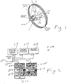
- the O-XYZ is the world coordinate system.
- the X-Y-Z axis gives the physical coordinates for the reconstructed voxels.
- the Z-axis is the rotation axis.
- the t-s axis is the rotated gantry X-Y coordinate system. The s-axis always passes through the x-ray source and is perpendicular to the detector plane.
- the coordinates used in the discussion are shown in Figure 1 and are defined relative to an x-ray source 102, a detector 104 and a gantry 106. It is assumed that the projection of the object P ( ⁇ ) at angle ⁇ is indexed by detector coordinates u and v. The reconstructed voxel values are indexed by physical coordinates x, y , and z. The center of rotation is the z-axis.
- the distance from the x-ray focal spot to the rotation axis is d so .
- the vertical axis of the detector can be moved to the z-axis.
- the pixel sizes at the z-axis can be made one.
- ( t , s ) is the coordinate in gantry system, which is the rotation transform of the X - Y axis with angle ⁇ .
- the reconstruction volume be N x ⁇ N y ⁇ N z voxels in the x, y , and z directions.
- d ⁇ be the angle difference between consecutive angle position
- P ⁇ ( i , i ) is N i ⁇ N j pixels.
- the complexity of the problem is roughly linear with the total number of voxels and linear with the number of projection view angles. Doubling the number of voxels roughly doubles the processing time. Doubling the dimension in each direction produces an eight-fold increase in the required processing. Doubling the number of views doubles the processing. As the number of voxels increases, the number of angular views must also increase to maintain the same peripheral resolution.
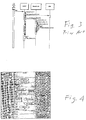
- the Intel x86 architecture diagram is shown in figure 2 .
- the Intel processor 200 has multiple execution units (EU's) to do integer and float operations simultaneously.
- EU execution units
- ALUO 202 and ALUI 204 there are two integer unit (ALUO 202 and ALUI 204), one float unit (FPU) 206, one MMX unit 208 to process 8-bit and 16-bit integers in parallel, and one Streaming SIMD Executing unit (SSE) to process four 32-bit single-precision float point data in parallel 210.
- ALUO 202 and ALUI 204 there are two integer unit (ALUO 202 and ALUI 204), one float unit (FPU) 206, one MMX unit 208 to process 8-bit and 16-bit integers in parallel, and one Streaming SIMD Executing unit (SSE) to process four 32-bit single-precision float point data in parallel 210.
- SSE Streaming SIMD Executing unit
- the SIMD instruction in the SSE
- the Pentium III processor has five pipelines 222 to exploit the parallelism in instruction execution. In each clock cycle, the processor core may dispatch zero or one ⁇ op on a port to any of the five pipelines for a maximum issue bandwidth of five ⁇ ops per cycle. Each pipeline connects to different EUs. For all different versions of the C/C+ + compiler for Intel processor, the normal C/C+ + code will only be able to generate code to utilize the integer unit ALU and float unit FPU. To use the hardware resource of the MMX unit and the SSE unit, either special intrinsic or manually written assembler code is used. There are two levels of cache in Pentium III processor.
- Level one (L1) cache is the on-chip cache subsystem and consists of two 16-Kbyte four-way set associative caches with a cache line length of 32bytes for instruction and data.
- the data cache has eight banks interleaved on four-byte boundaries.
- Level two (L2) cache is off-chip but in the same processor package. It usually has a size from 128 Kbytes to 1 Mbyte. L2 usually has a latency from 4 to 10 cycles for data access. When the processor needs to fetch instructions or data, L1 is much faster than L2, and L2 is faster than access to main memory.
- the Instruction-Level Parallelism has two basic kinds: Individual instructions are overlapped (executed at the same time) in the processor, a given instruction is decomposed into sub operations and the sub operations are overlapped.
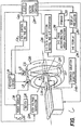
- the normal FACBR implementation can be explained with a unified modeling language (UML) sequence diagram as Figure 3 .
- UML unified modeling language
- the reconstruction is finished, and the data are saved or rendered in a 3D display.
- the filtering time is about 1/15 to 1/30 of the backprojection time or less.
- HD is used to decrease and make ALU units work in parallel.
- the SSE unit is independent from the FPU unit and the MMX unit, the SSE unit can work with the ALU unit, the MMX unit and even the FPU unit simultaneously, thus allowing a hybrid execute mode for either PF data or HD.
- the map data and some intermediate results can be processed by the ALU in fixed point data format, and the reconstruction data and finally output results can be processed in floating point format. That hybrid data format for different data and stages can improve the EU's efficiency.
- PF data the best method is to use the MMX unit to adjust the data address and map data, and to use the SSE to do the backprojection calculation.
- the MMX can process data address and map data for two or more points, while the ALU can deal with only one point.
- the HE method for PF can be shown as a UML activity diagram in Figure 4 .
- the second parallelism consideration is the data partition schema.
- the reconstruction data are partitioned into different sub-units.
- a data partition scheme is shown in Figure 5 .
- Data are stored in memory as a one-dimensional array, in which the index of each data point increases for z , then for x and last for y .
- Data are processed in z-lines because the same projection data u value can be used for one z-line.
- the projection data used to do backprojection for voxels in one z-line are actually in two adjacent u-lines, since four adjacent points (two in each of the adjacent u-lines) are used to interpolate the data for one voxel in the z-line.
- the reconstruction accuracy of the implementation will be determined using computer-simulated phantom.
- the reconstruction error noise level and uniformity of the reconstructed images are quantified using both pure float point implementation and HD computing implementation, and the reconstruction results from the two implementations are compared with both simulated phantom and experimental phantom data.
- the speedup of MC implementation is evaluated compared to normal pure float-point computing reconstruction.
- Experimental phantom data are also used to evaluate the effectiveness of the implementation in the real world.
- the Shepp Logan phantom is used as a general precision error compare reference.
- the cylinder phantom is used to compare the precision error at different z positions. Normally, the Feldkamp Algorithm has the best result at center slice, and the precision error increases for the slices at two ends.
- the cylinder phantom is used to check whether the HD and PF precision error varies with z-distance to center.
- the total FACBR time contains the filtering time and backprojection time; the filtering time takes only a small part in the total time.
- Table 3 Filter Mode 4N_ext SSE_4N 2N_ext SSE_2N Time (s) 146.891 58.163 78.753 35.310 Speed-up 2.5255 2.2303
- the backprojection process is the most time-consuming part of FACBR.
- the acceleration of five implementations has been tested; the results are shown in Table 4 below.
- the tests used 288 512 2 projections to reconstruct 512 3 data. All the reconstructions are run with a cylinder boundary.
- the program runs in Windows NT 4.0 and takes 95% to 98% of the processor time.
- the first column is the traditional PF method with boundary
- the second is PF with data partition
- the third one is HD method
- the forth is HD data with HE
- the fifth one is PF with SSE acceleration
- the last one is PF with HE.
- the results shows that HD provides a 3 to 3.5 speed-up over the traditional implementation, and HE-HD provides a 4 to 5 speed-up, which is almost same as PF with SSE.
- the HE-HD does not involve the SSE unit, so that cheaper processor like the Celeron can be used to get almost the same performance with SSE-PF; second, a higher speed-up can be obtained by using a functional unit which works with fixed-point data in the same way in which the SSE works with floating-point data; such functionality already appears in the Pentium IV processor.
- the HE-PF is the most efficient method in a Pentium III processor. Reconstruction with sphere boundary, along with hybrid computing combining the power of the MMX and SSE units, provides a speed-up of 5 to 6 and a reconstruction time of 15.03 minutes for 512 3 FACBR. The timing result will be better with a higher clock frequency processor and an SMP computer.
- Table 5 below shows the effective t unit of different slices for the HE-HD and HE-PF methods. Since the program runs in a multi-processor operating system, the processor time resource varies over time, so that the effective t unit also varies over time. Basically, t unit becomes stable as the slice number increases. When the slice number is less than 4 or the data are not 16-bytes aligned, the processor is unable to use SSE, and then the t unit is greater than when SSE is available. Therefore, the time for a single slice can be greater than for other slices.
- the error ratio will be calculated for each pixel. Then, the average error ratio will be calculated for the whole comparing Region of Interest (ROI).
- ROI Region of Interest
- the precision error has been determined for a HD reconstructed image relative to a simulated phantom image and a PF reconstructed image.
- the precision error between the HD image and the PF image is less 0.03%; for the cylinder phantom, the E HP is less than 0.02%.
- the HD image keeps a good precision compared to the PF image.
- the E HP contributes less than 5% of the total error percentage to the simulated phantom image. This means that the algorithm introduces more than 95% of the total error.
- the HD images have enough precision and are comparable to PF images.
- FIG. 6 An apparatus on which the invention can be implemented is shown in Fig. 6 , which is reproduced from Fig. 9 of the above-referenced U.S. Patent No. 5,999,587 .
- a 3-D reconstruction is obtained by stacking a series of slices.
- a direct reconstruction of an object can be obtained.
- FIG. 6 it is shown how the cone-beam tomography system 600 of the present invention can be used to obtain a direct 3-D reconstruction of an object.
- the cone beam volume CT scanning apparatus 600 is illustrated in a simplified block diagram form.
- the invention may preferably be employed in conjunction with such a cone beam volume CT scanning apparatus to generate a 3-D reconstruction matrix of the object. Based on the 3-D reconstruction matrix, the desired three-dimensional display can be obtained.
- a cone beam volume CT scanning apparatus examines a body P using a cone shaped radiation beam 604 which traverses a set of paths across the body.
- an X-ray source 610 and a 2-D detector 611 are mounted on a gantry frame 602 that rotates around the body P being examined.
- the operating voltage for the x-ray source is obtained from a conventional high-voltage generator 608 in such a manner that the x-ray source 610 produces the desired cone-shaped beam of radiation when the high-voltage is applied to it.
- the high- voltage generator 608 is energized by means of a power source 618, through a switch 616.
- a contrast solution injector 640 can be used as needed.
- a first motor 612 is also powered by the power source 618 such that it drives the gantry frame 602 in its orbit about the body, for example, in a clockwise direction as shown by the arrows adjacent to the frame.
- the power source 618 is turned on by means of switch 620 or other conventional control devices, in order to initiate a measurement sequence.
- a speed control circuit 614 is used to control the speed of rotation of the gantry frame 602 and to provide an output control signal which indicates when the speed of the motor 712 is at the desired level for taking measurements.
- the output from the rotational control 614 may also be utilized to operate the switch 616 such that the high-voltage generator 608 is only turned on when the gantry frame 602 is driven at the desired speed for making measurements.
- a tilt control 615 is utilized to cause the gantry frame 602 to tilt by a relatively small angle of ⁇ 15° to ⁇ 30°, by means of the gantry frame tilt motor 613. That tilting allows the acquisition of arc projection data on the perpendicular arc.
- Such geometry results in a complete set of data for an object with a 25-40 cm diameter corresponding to a 37-60 cm field at the detectors 611 with a magnification of 1.5.
- the tilting of the gantry 602 is generally available in a standard CT gantry, to acquire arc projections, the minimal modification of a standard CT gantry has to be made such that the tilting of the gantry, the x-ray exposure timing and the projection acquisition are synchronized by the system control computer 624 as shown in FIG. 6 .
- the circle-plus-arc geometry can be implemented in one of the following two ways.
- the gantry 602 is tilted to a small angle ( ⁇ 15° to ⁇ 30°) and then the x-ray tube 610 and the 2-D detector 611 are rotated while the gantry 602 is tilted.
- a half set of arc projections will be acquired only when the x-ray tube 610 and the 2-D detector 611 are at the rotation angle of 0°.
- the circle projections will be acquired at the preset rotation angle positions.
- the gantry 602 When the circle projection acquisition is completed, the gantry 602 will be tilted toward -15° to -30°. Another half set of arc projections will be acquired only when the x-ray tube 610 and the 2-D detector 611 are at the rotation angle of 0°.
- the second alternative method is to mechanically modify a standard CT gantry such that two short arc orbits are added to the gantry, and the x-ray tube 610 and the 2-D detector 611 can be moved on the arc to acquire the arc projections and on the circle to acquire the circle projections.
- One arc constitutes the orbit of the x-ray tube 610 and the other arc is the orbit of the 2-D detector 611.
- the two arc orbits are mounted 180° apart from each other.
- the x-ray tube 610 and the 2-D detector 611 are synchronously moved on the arc orbits to acquire arc projections. Then, the x-ray tube 610 and the 2-D detector 611 are rotated on the gantry to acquire circle projections.
- a 2-D detector 611 Mounted on the gantry frame 602 opposite the x-ray source 610 is a 2-D detector 611 which has a dynamic range equal to or greater than 1000:1 and an image lag of less than 10%, for example a selenium thin film transistor (STFT) array or a silicon STFT array, in order to provide 2-D projections that correspond to an x-ray attenuation signal pattern.
- STFT selenium thin film transistor
- the x-ray source 610 and the 2-D detector 611 are mounted on the gantry frame 602 in such a manner that they both move synchronously.
- the cone-shaped beam of radiation 604 generated by the x-ray source 610 is projected through the body or object under test.
- the 2-D detector cone measures the radiation transmitted along the set of beam paths across the cone.
- a continuous series of two-dimensional detectors can be fixedly mounted proximate to the gantry frame 602 and the x-ray source 610 is mounted to the gantry frame such that, upon rotation of the gantry frame, the cone-shaped radiation beam 604 is projected through the body P under test and sequentially received by each of the series of detectors.
- a 2-D projection acquisition control and A/D conversion unit 626 under control of the scanning pulses sequentially obtained from the system control computer 624, which includes the clock 622, receives a sequence of outputs corresponding to different lines of the 2-D detector 611.
- Each line of the 2-D detector consists of many detection cells (at least > 100).
- the output of each detector cell represents a line integral of attenuation values measurable along one of the respective beam paths.
- the cone-shaped beam 604 subtends a cone angle sufficient to include the entire region of interest of the body.
- the analog-to-digital conversion unit 626 serves to digitize the projection signals and to save them in the 3-D image reconstruction array processor 628 and storage device 630.
- the method employed by the 3-D image reconstruction array processor 628 is the invented algorithm and method described in this application.
- the 3-D image reconstruction array processor 628 serves to transform the digitized projection signals into x-ray attenuation data vectors.
- the x-ray attenuation data matrix corresponds to x-ray attenuation at spaced grid locations within the body trunk being examined. Each data element of the matrix represents an x-ray attenuation value and the location of the element corresponds to a respective 3-D grid location within the body.
- a display processor 632 obtains the data stored as 3-D x-ray attenuation signal patterns in the memory storage 630, processes that data as previously described, and then the desired 3-D images are displayed on a 3-D display device 634.
- the 3-D image reconstruction array processor 632 may, for example, be a computer as described above with one or more Intel or Intel-compatible x86-class microprocessors. However, any processor or processors capable of the same or substantially the same parallel operation can be used.
- the present invention specific to x86 processors; instead, the invention can be used with any processor capable of implementing the algorithms described above and has particular utility with any processor that has a floating-point unit that can process more than one single-precision 32-bit datum within one instruction set and a fixed-point unit that can process more than one 16- or 32-bit data within one instruction set. Therefore, the present invention should be construed as limited only by the appended claims.
Landscapes
- Health & Medical Sciences (AREA)
- Engineering & Computer Science (AREA)
- Life Sciences & Earth Sciences (AREA)
- Physics & Mathematics (AREA)
- Theoretical Computer Science (AREA)
- Medical Informatics (AREA)
- Pathology (AREA)
- General Physics & Mathematics (AREA)
- General Health & Medical Sciences (AREA)
- Radiology & Medical Imaging (AREA)
- Nuclear Medicine, Radiotherapy & Molecular Imaging (AREA)
- Heart & Thoracic Surgery (AREA)
- Animal Behavior & Ethology (AREA)
- Biophysics (AREA)
- Pulmonology (AREA)
- Optics & Photonics (AREA)
- Veterinary Medicine (AREA)
- High Energy & Nuclear Physics (AREA)
- Biomedical Technology (AREA)
- Public Health (AREA)
- Molecular Biology (AREA)
- Surgery (AREA)
- Mathematical Optimization (AREA)
- Mathematical Physics (AREA)
- Pure & Applied Mathematics (AREA)
- Algebra (AREA)
- Mathematical Analysis (AREA)
- Chemical & Material Sciences (AREA)
- Analytical Chemistry (AREA)
- Biochemistry (AREA)
- Immunology (AREA)
- Apparatus For Radiation Diagnosis (AREA)
- Image Processing (AREA)
- Ultra Sonic Daignosis Equipment (AREA)
Claims (28)
- Système de création d'une image en trois dimensions représentative d'une partie intérieure d'un objet, le système comprenant :un balayeur par rayonnement, qui crée des signaux de projection en envoyant un rayonnement à travers l'objet sur un détecteur etun ordinateur recevant les signaux de projection pour créer l'image en trois dimensions en effectuant une pluralité de calculs sur les signaux de projection, l'ordinateur comprenant au moins une unité de traitement à virgule fixe et au moins une unité de traitement à virgule flottante, la au moins une unité de traitement à virgule fixe fonctionnant en parallèle avec la au moins une unité de traitement à virgule flottante, l'ordinateur étant programmé pour subdiviser la pluralité de calculs en une première pluralité de calculs à effectuer dans la au moins une unité de traitement à virgule fixe et en une deuxième pluralité de calculs à effectuer dans la au moins une unité de traitement à virgule flottante,dans lequel le balayeur par rayonnement est un balayeur par rayonnement à faisceau en cône, le faisceau de rayonnement est un faisceau de rayonnement en cône et les signaux de projection sont des signaux de projection de faisceau en cône,caractériséen ce que la première pluralité de calculs comprend la création d'une topographie de projection, la création de la topographie de projection comprenant la topographie d'un système x, y, z de coordonnées universel pour coordonner un système u, t, s du détecteur, u étant indépendant de z, et en ce que la deuxième pluralité de calculs comprend la rétroprojection des signaux de projection à faisceau de cône, en conformité avec la topologie de projection pour produire l'image.
- Système suivant la revendication 1, dans lequel l'ordinateur organise les signaux de projection à faisceau de cône en des lignes z, pour lesquelles z varie mais x et y sont constants ; et
l'ordinateur effectue la rétroprojection pour chacune des lignes z. - Système suivant la revendication 2, dans lequel l'ordinateur comprend en outre un cache, qui est suffisamment grand pour contenir l'une des lignes z.
- Système suivant la revendication 2, dans lequel, après que l'ordinateur a effectué la rétroprojection pour toutes les lignes z pour former l'image sous la forme d'une pluralité de voxels, l'ordinateur effectue une opération de transposition en trois dimensions sur les voxels de l'image pour organiser les voxels en des lignes x pour lesquelles x varie mais y et z sont constants.
- Système suivant la revendication 1, dans lequel :une limite de l'objet est connue à priori etl'image en trois dimensions est créée seulement au sein de la limite.
- Système suivant la revendication 1, dans lequel les signaux de projection sont traités comme des données pures à virgule flottante.
- Système suivant la revendication 1, dans lequel les signaux de projection sont traités comme un mélange de données à virgule flottante et à virgule fixe.
- Système suivant la revendication 1, dans lequel l'ordinateur comprend un microprocesseur sur lequel la au moins une unité de traitement à virgule fixe, qui peut traiter plus qu'une donnée en nombre entier de 16 bit ou de 32 bit dans un seul jeu d'instruction, et la au moins une unité de traitement à virgule flottante, qui peut traiter plus qu'une donnée à virgule flottante de 32 bit à précision unique dans un seul jeu d'instruction, sont mises en oeuvre.
- Système suivant la revendication 8, dans lequel l'ordinateur comprend une pluralité desdits processeurs, chacun d'entre eux comprenant au moins l'unité de traitement à virgule fixe, qui peut traiter plus qu'une donnée en nombre entier à 16 bit ou 32 bit dans un seul jeu d'instruction, et au moins l'unité de traitement à virgule flottante, qui peut traiter plus qu'une donnée à virgule flottante à 32 bit à précision unique dans un seul jeu d'instruction.
- Système suivant la revendication 1, dans lequel l'image est une distribution linéaire de coefficients d'atténuation de la partie intérieure de l'objet.
- Procédé de création d'une image en trois dimensions représentative d'une partie intérieure d'un objet, procédé dans lequel :(a) on envoie un faisceau à travers l'objet sur un détecteur pour créer des signaux de projection et(b) on reçoit les signaux de projection et on crée l'image en trois dimensions en effectuant une pluralité de calculs sur les signaux de projection du faisceau ;dans lequel on effectue le stade (b) sur un ordinateur comprenant au moins une unité de traitement à virgule fixe et au moins une unité de traitement à virgule flottante, la au moins une unité de traitement à virgule fixe fonctionnant en parallèle avec la au moins une unité de traitement à virgule flottante, l'ordinateur subdivisant la pluralité de calculs en une première pluralité de calculs à effectuer dans la au moins une unité de traitement à virgule fixe, et en une deuxième pluralité de calculs à effectuer dans la au moins une unité de traitement à virgule flottante,
dans lequel le faisceau est un faisceau en cône et les signaux de projection sont des signaux de projection de faisceau en cône,
caractérisé
en ce que la première pluralité de calculs comprend la création d'une topographie de projection, la création de la topographie de projection comprenant la topographie d'un système x, y, z de coordonnées universel pour coordonner un système u, t, s du détecteur, u étant indépendant de z, et en ce que la deuxième pluralité de calculs comprend la rétroprojection des signaux de projection à faisceau de cône, en conformité avec la topologie de projection pour produire l'image reconstruite. - Procédé suivant la revendication 11, dans lequel :l'ordinateur organise les signaux de projection à faisceau de cône en des lignes z, pour lesquelles z varie mais x et y sont constants, etl'ordinateur effectue la rétroprojection pour chacune des lignes z.
- Procédé suivant la revendication 12, dans lequel l'ordinateur comprend en outre un cache, qui est suffisamment grand pour contenir l'une des lignes z.
- Procédé suivant la revendication 12, dans lequel, après que l'ordinateur a effectué la rétroprojection pour toutes les lignes z pour former l'image sous la forme d'une pluralité de voxels, l'ordinateur effectue une opération de transposition en trois dimensions sur les voxels de l'image pour organiser les voxels en des lignes x pour lesquelles x varie mais y et z sont constants.
- Procédé suivant la revendication 11, dans lequel :une limite de l'objet est connue à priori etl'image en trois dimensions est créée seulement au sein de la limite.
- Procédé suivant la revendication 11, dans lequel les signaux de projection sont traités comme des données pures à virgule flottante.
- Procédé suivant la revendication 11, dans lequel les signaux de projection sont traités comme un mélange de données à virgule flottante et à virgule fixe.
- Procédé suivant la revendication 11, dans lequel l'ordinateur comprend un microprocesseur sur lequel la au moins une unité de traitement à virgule fixe, qui peut traiter plus qu'une donnée en nombre entier de 16 bit ou de 32 bit dans un seul jeu d'instruction, et la au moins une unité de traitement à virgule flottante, qui peut traiter plus qu'une donnée à virgule flottante de 32 bit à précision unique dans un seul jeu d'instruction, sont mises en oeuvre.
- Procédé suivant la revendication 18, dans lequel l'ordinateur comprend une pluralité desdits processeurs, chacun d'entre eux comprenant au moins l'unité de traitement à virgule fixe, qui peut traiter plus qu'une donnée en nombre entier à 16 bit ou 32 bit dans un seul jeu d'instruction, et au moins l'unité de traitement à virgule flottante, qui peut traiter plus qu'une donnée à virgule flottante à 32 bit à précision unique dans un seul jeu d'instruction.
- Procédé suivant la revendication 18, dans lequel l'image est une distribution linéaire de coefficients d'atténuation de la partie intérieure de l'objet.
- Procédé suivant la revendication 11, dans lequel on effectue le stade (b) en utilisant un algorithme de reconstruction de faisceau en cône de rétroprojection filtrée.
- Procédé suivant la revendication 21, dans lequel on effectue l'algorithme de reconstruction du faisceau en cône de rétroprojection filtrée en utilisant une informatique hybride utilisant une technique à donnée multiple d'instruction simple.
- Procédé suivant la revendication 22, dans lequel on effectue l'algorithme de reconstruction du faisceau en cône de rétroprojection filtrée en utilisant une mise en place multiple sur une pluralité de processeurs.
- Procédé suivant la revendication 11, dans lequel l'objet comprend du tissu mou.
- Procédé suivant la revendication 11, dans lequel on effectue le stade (b) en utilisant un langage d'assemblage écrit manuellement.
- Procédé suivant la revendication 11, dans lequel on effectue le stade (b) par reconstruction Feldkamp de faisceau en cône en :(i) effectuant un calcul hybride utilisant une donnée multiple d'instruction simple (SIMD) sur une pluralité d'unités d'exécution ;(ii) utilisant une mise en place multiple et un support à fibre dans un système fonctionnel, de manière à permettre automatiquement un parallélisme de reconstruction date I/O efficace d'environnement de multiprocesseur et(iii) optimisant un accès à la mémoire et au cache par partition de donnée.
- Procédé suivant la revendication 11, dans lequel on effectue le stade (b) par traitement parallèle sur un microprocesseur unique ou sur des processeurs multiples en utilisant un calcul hybride pour accélérer une reconstruction d'un faisceau en cône pour reconstruire du tissu mou.
- Procédé suivant la revendication 11, dans lequel on effectue le stade (b) par mise en place multiple seulement lorsqu'une pluralité de processeurs est disponible.
Applications Claiming Priority (3)
| Application Number | Priority Date | Filing Date | Title |
|---|---|---|---|
| US09/784,331 US6477221B1 (en) | 2001-02-16 | 2001-02-16 | System and method for fast parallel cone-beam reconstruction using one or more microprocessors |
| PCT/US2002/004183 WO2002067223A2 (fr) | 2001-02-16 | 2002-02-13 | Systeme et procede pour une reconstruction rapide de faisceaux coniques paralleles a l'aide d'au moins un microprocesseur |
| US784331 | 2007-04-06 |
Publications (2)
| Publication Number | Publication Date |
|---|---|
| EP1366469A2 EP1366469A2 (fr) | 2003-12-03 |
| EP1366469B1 true EP1366469B1 (fr) | 2017-10-04 |
Family
ID=25132101
Family Applications (1)
| Application Number | Title | Priority Date | Filing Date |
|---|---|---|---|
| EP02720960.0A Expired - Lifetime EP1366469B1 (fr) | 2001-02-16 | 2002-02-13 | Systeme et procede pour une reconstruction rapide de faisceaux coniques paralleles a l'aide d'au moins un microprocesseur |
Country Status (6)
| Country | Link |
|---|---|
| US (1) | US6477221B1 (fr) |
| EP (1) | EP1366469B1 (fr) |
| CN (1) | CN1284122C (fr) |
| AU (1) | AU2002251922B2 (fr) |
| CA (1) | CA2438387A1 (fr) |
| WO (1) | WO2002067223A2 (fr) |
Families Citing this family (52)
| Publication number | Priority date | Publication date | Assignee | Title |
|---|---|---|---|---|
| US6987831B2 (en) | 1999-11-18 | 2006-01-17 | University Of Rochester | Apparatus and method for cone beam volume computed tomography breast imaging |
| US7430271B2 (en) * | 2000-11-13 | 2008-09-30 | Digitome Corporation | Ray tracing kernel |
| US20020169680A1 (en) * | 2001-05-10 | 2002-11-14 | International Business Machines Corporation | Method and apparatus for building commercial distributed computing networks via computer cost subsidization |
| US6741730B2 (en) * | 2001-08-10 | 2004-05-25 | Visiongate, Inc. | Method and apparatus for three-dimensional imaging in the fourier domain |
| US6771733B2 (en) * | 2001-08-16 | 2004-08-03 | University Of Central Florida | Method of reconstructing images for spiral and non-spiral computer tomography |
| US6638226B2 (en) * | 2001-09-28 | 2003-10-28 | Teratech Corporation | Ultrasound imaging system |
| JP3870105B2 (ja) * | 2002-02-22 | 2007-01-17 | ジーイー・メディカル・システムズ・グローバル・テクノロジー・カンパニー・エルエルシー | 逆投影方法およびx線ct装置 |
| US6904117B2 (en) * | 2002-10-30 | 2005-06-07 | Toshiba Corporation | Tilted gantry helical cone-beam Feldkamp reconstruction for multislice CT |
| DE10304662A1 (de) * | 2003-02-05 | 2004-08-19 | Siemens Ag | Verfahren zur Erzeugung von Bildern in der Computertomographie mit einem 3D-Bildrekonstruktionsverfahren |
| US7535988B2 (en) * | 2003-05-27 | 2009-05-19 | Clean Earth Technologies, Llc | Method for fast image reconstruction with compact radiation source and detector arrangement using computerized tomography |
| US7134036B1 (en) * | 2003-12-12 | 2006-11-07 | Sun Microsystems, Inc. | Processor core clock generation circuits |
| US7362843B2 (en) * | 2004-09-23 | 2008-04-22 | General Electric Company | System and method for reconstruction of cone beam tomographic projections with missing data |
| WO2006116316A2 (fr) | 2005-04-22 | 2006-11-02 | University Of Chicago | Systeme d'imagerie |
| CA2608119A1 (fr) | 2005-05-11 | 2006-11-16 | Optosecurity Inc. | Procede et systeme d'inspection de bagages, de conteneurs de fret ou de personnes |
| US7991242B2 (en) | 2005-05-11 | 2011-08-02 | Optosecurity Inc. | Apparatus, method and system for screening receptacles and persons, having image distortion correction functionality |
| US7492858B2 (en) * | 2005-05-20 | 2009-02-17 | Varian Medical Systems, Inc. | System and method for imaging and treatment of tumorous tissue in breasts using computed tomography and radiotherapy |
| US7646842B2 (en) * | 2005-09-23 | 2010-01-12 | General Electric Company | Methods and apparatus for reconstructing thick image slices |
| US20070132754A1 (en) * | 2005-12-12 | 2007-06-14 | Intel Corporation | Method and apparatus for binary image classification and segmentation |
| EP1966766A1 (fr) * | 2005-12-29 | 2008-09-10 | Intel Corporation | Applications de l'arithmetique d'intervalles pour reduire le nombre de calculs dans les problemes de lancer de rayons |
| CN103908282B (zh) * | 2006-02-27 | 2016-05-18 | 罗切斯特大学 | 锥束ct动态成像的方法和设备 |
| US20070274435A1 (en) * | 2006-02-27 | 2007-11-29 | Ruola Ning | Phase contrast cone-beam CT imaging |
| WO2007126932A1 (fr) * | 2006-03-28 | 2007-11-08 | Xoran Technologies, Inc. | Scanner ct avec détermination automatique du volume d'intérêt |
| WO2007124338A1 (fr) * | 2006-04-19 | 2007-11-01 | Xoran Technologies, Inc. | scanner CT avec marqueurs non suivis |
| DE102007020879A1 (de) | 2006-05-10 | 2009-04-02 | Gachon University Of Medicine & Science Industry-Academic Cooperation Foundation | Verfahren und Vorrichtung für die äußerst schnelle Symmetrie- und SIMD- gestützte Projektion/Rückprojektion für die 3D-PET-Bildrekonstruktion |
| US7899232B2 (en) | 2006-05-11 | 2011-03-01 | Optosecurity Inc. | Method and apparatus for providing threat image projection (TIP) in a luggage screening system, and luggage screening system implementing same |
| CN100386779C (zh) * | 2006-06-02 | 2008-05-07 | 清华大学 | 基于通用图形显示卡的被测体正投影与反投影方法 |
| US8494210B2 (en) | 2007-03-30 | 2013-07-23 | Optosecurity Inc. | User interface for use in security screening providing image enhancement capabilities and apparatus for implementing same |
| DE102006036327A1 (de) * | 2006-08-03 | 2008-02-14 | Siemens Ag | Verfahren zum Bereitstellen von 3D-Bilddaten und System zum Aufnehmen von Röntgenbildern |
| US8217937B2 (en) * | 2007-03-28 | 2012-07-10 | The Aerospace Corporation | Isosurfacial three-dimensional imaging system and method |
| WO2009026587A1 (fr) * | 2007-08-23 | 2009-02-26 | Fischer Medical Technologies, Inc. | Mammographie par tomodensitométrie calculée améliorée et système de biopsie |
| US8023767B1 (en) | 2008-03-10 | 2011-09-20 | University Of Rochester | Method and apparatus for 3D metal and high-density artifact correction for cone-beam and fan-beam CT imaging |
| US7940891B2 (en) | 2008-10-22 | 2011-05-10 | Varian Medical Systems, Inc. | Methods and systems for treating breast cancer using external beam radiation |
| US8285971B2 (en) * | 2008-12-16 | 2012-10-09 | International Business Machines Corporation | Block driven computation with an address generation accelerator |
| US8327345B2 (en) * | 2008-12-16 | 2012-12-04 | International Business Machines Corporation | Computation table for block computation |
| US8458439B2 (en) * | 2008-12-16 | 2013-06-04 | International Business Machines Corporation | Block driven computation using a caching policy specified in an operand data structure |
| US8407680B2 (en) * | 2008-12-16 | 2013-03-26 | International Business Machines Corporation | Operand data structure for block computation |
| US8281106B2 (en) * | 2008-12-16 | 2012-10-02 | International Business Machines Corporation | Specifying an addressing relationship in an operand data structure |
| WO2010093357A1 (fr) * | 2009-02-11 | 2010-08-19 | Tomotherapy Incorporated | Ensemble support de cible et procédé de protection de la cible |
| US7949095B2 (en) | 2009-03-02 | 2011-05-24 | University Of Rochester | Methods and apparatus for differential phase-contrast fan beam CT, cone-beam CT and hybrid cone-beam CT |
| CN101664583B (zh) * | 2009-09-09 | 2012-05-09 | 深圳市海博科技有限公司 | 基于cuda的剂量计算优化方法和系统 |
| KR101973221B1 (ko) | 2011-09-07 | 2019-04-26 | 라피스캔 시스템스, 인코포레이티드 | 적하목록 데이터를 이미징/검출 프로세싱에 통합시키는 x-선 검사시스템 |
| WO2014137325A1 (fr) | 2012-03-05 | 2014-09-12 | University Of Rochester | Procédés et appareils pour tdm à faisceau conique à contraste de phase différentiel et tdm à faisceau conique hybride |
| CN102877828A (zh) * | 2012-09-09 | 2013-01-16 | 山西山地物探技术有限公司 | 一种三维多井联合井地ct成像方法 |
| US9364191B2 (en) | 2013-02-11 | 2016-06-14 | University Of Rochester | Method and apparatus of spectral differential phase-contrast cone-beam CT and hybrid cone-beam CT |
| US9443633B2 (en) | 2013-02-26 | 2016-09-13 | Accuray Incorporated | Electromagnetically actuated multi-leaf collimator |
| WO2014194944A1 (fr) * | 2013-06-05 | 2014-12-11 | Ev Group E. Thallner Gmbh | Dispositif de mesure et procédé de détermination d'une force de pression |
| CN105806858B (zh) * | 2014-12-31 | 2019-05-17 | 北京固鸿科技有限公司 | Ct检测方法和ct设备 |
| GB2564038B (en) | 2016-02-22 | 2021-11-10 | Rapiscan Systems Inc | Systems and methods for detecting threats and contraband in cargo |
| US10482632B2 (en) * | 2017-04-28 | 2019-11-19 | Uih America, Inc. | System and method for image reconstruction |
| CN109157215B (zh) * | 2018-08-29 | 2021-09-28 | 中国医学科学院生物医学工程研究所 | 一种基于系统矩阵的磁感应磁声电导率图像重建方法 |
| EP4141427A1 (fr) * | 2020-11-18 | 2023-03-01 | Jed Co., Ltd | Dispositif d'inspection par rayons x |
| CN116543088B (zh) * | 2023-07-07 | 2023-09-19 | 有方(合肥)医疗科技有限公司 | Cbct图像重建方法及装置 |
Citations (1)
| Publication number | Priority date | Publication date | Assignee | Title |
|---|---|---|---|---|
| US6002738A (en) * | 1995-07-07 | 1999-12-14 | Silicon Graphics, Inc. | System and method of performing tomographic reconstruction and volume rendering using texture mapping |
Family Cites Families (17)
| Publication number | Priority date | Publication date | Assignee | Title |
|---|---|---|---|---|
| US5253171A (en) * | 1990-09-21 | 1993-10-12 | General Electric Company | Parallel processing method and apparatus based on the algebra reconstruction technique for reconstructing a three-dimensional computerized tomography (CT) image from cone beam projection data |
| US5257183A (en) | 1990-12-21 | 1993-10-26 | General Electric Company | Method and apparatus for converting cone beam X-ray projection data to planar integral and reconstructing a three-dimensional computerized tomography (CT) image of an object |
| US5170439A (en) | 1991-06-11 | 1992-12-08 | Picker International, Inc. | Cone beam reconstruction using combined circle and line orbits |
| US5365560A (en) | 1991-07-29 | 1994-11-15 | General Electric Company | Method and apparatus for acquiring a uniform distribution of radon data sufficiently dense to constitute a complete set for exact image reconstruction of an object irradiated by a cone beam source |
| US5333164A (en) * | 1991-12-11 | 1994-07-26 | General Electric Company | Method and apparatus for acquiring and processing only a necessary volume of radon data consistent with the overall shape of the object for efficient three dimensional image reconstruction |
| US5390226A (en) | 1992-07-02 | 1995-02-14 | General Electric Company | Method and apparatus for pre-processing cone beam projection data for exact three dimensional computer tomographic image reconstruction of a portion of an object |
| GB2271261A (en) * | 1992-10-02 | 1994-04-06 | Canon Res Ct Europe Ltd | Processing image data |
| US5517602A (en) | 1992-12-03 | 1996-05-14 | Hewlett-Packard Company | Method and apparatus for generating a topologically consistent visual representation of a three dimensional surface |
| US5278884A (en) | 1992-12-18 | 1994-01-11 | General Electric Company | Complete 3D CT data acquisition using practical scanning paths on the surface of a sphere |
| US5461650A (en) | 1993-10-18 | 1995-10-24 | General Electric Company | Method and system for pre-processing cone beam data for reconstructing free of interpolation-induced artifacts a three dimensional computerized tomography image |
| US5400255A (en) | 1994-02-14 | 1995-03-21 | General Electric Company | Reconstruction of images from cone beam data |
| US5671265A (en) | 1995-07-14 | 1997-09-23 | Siemens Corporate Research, Inc. | Evidential reconstruction of vessel trees from X-ray angiograms with a dynamic contrast bolus |
| JPH09149902A (ja) | 1995-12-01 | 1997-06-10 | Hitachi Medical Corp | X線断層撮影方法および装置 |
| CA2227531C (fr) * | 1997-01-20 | 2003-03-18 | Hitachi, Ltd. | Unite de traitement graphique et systeme de traitement graphique |
| US6078638A (en) * | 1998-09-30 | 2000-06-20 | Siemens Corporate Research, Inc. | Pixel grouping for filtering cone beam detector data during 3D image reconstruction |
| US6343108B1 (en) * | 1999-06-18 | 2002-01-29 | Philips Medical Systems (Cleveland), Inc. | Cone beam scanner using oblique surface reconstructions |
| US6201849B1 (en) * | 1999-08-16 | 2001-03-13 | Analogic Corporation | Apparatus and method for reconstruction of volumetric images in a helical scanning cone-beam computed tomography system |
-
2001
- 2001-02-16 US US09/784,331 patent/US6477221B1/en not_active Expired - Lifetime
-
2002
- 2002-02-13 CN CNB028050894A patent/CN1284122C/zh not_active Expired - Lifetime
- 2002-02-13 CA CA002438387A patent/CA2438387A1/fr not_active Abandoned
- 2002-02-13 EP EP02720960.0A patent/EP1366469B1/fr not_active Expired - Lifetime
- 2002-02-13 AU AU2002251922A patent/AU2002251922B2/en not_active Ceased
- 2002-02-13 WO PCT/US2002/004183 patent/WO2002067223A2/fr not_active Application Discontinuation
Patent Citations (1)
| Publication number | Priority date | Publication date | Assignee | Title |
|---|---|---|---|---|
| US6002738A (en) * | 1995-07-07 | 1999-12-14 | Silicon Graphics, Inc. | System and method of performing tomographic reconstruction and volume rendering using texture mapping |
Also Published As
| Publication number | Publication date |
|---|---|
| US6477221B1 (en) | 2002-11-05 |
| CN1284122C (zh) | 2006-11-08 |
| CA2438387A1 (fr) | 2002-08-29 |
| CN1491404A (zh) | 2004-04-21 |
| US20020154727A1 (en) | 2002-10-24 |
| WO2002067223A3 (fr) | 2002-10-24 |
| EP1366469A2 (fr) | 2003-12-03 |
| AU2002251922B2 (en) | 2008-01-03 |
| WO2002067223A2 (fr) | 2002-08-29 |
Similar Documents
| Publication | Publication Date | Title |
|---|---|---|
| EP1366469B1 (fr) | Systeme et procede pour une reconstruction rapide de faisceaux coniques paralleles a l'aide d'au moins un microprocesseur | |
| AU2002251922A1 (en) | System and method for fast parallel cone-beam reconstruction using one or more microprocessors | |
| US7251307B2 (en) | Fan-beam and cone-beam image reconstruction using filtered backprojection of differentiated projection data | |
| Myagotin et al. | Efficient volume reconstruction for parallel-beam computed laminography by filtered backprojection on multi-core clusters | |
| US5901196A (en) | Reduction of hitlist size in spiral cone beam CT by use of local radon origins | |
| US20050047542A1 (en) | Image reconstruction method for divergent beam scanner | |
| Scherl et al. | Evaluation of state-of-the-art hardware architectures for fast cone-beam CT reconstruction | |
| US7209535B2 (en) | Fourier space tomographic image reconstruction method | |
| CA2056528A1 (fr) | Methode et appareil de traitement parallele de production d'images de tomographie tridimensionnelle assistee par ordinateur a partir de donnees de projection de faisceau conique ou d'integrales planes | |
| Keck et al. | GPU-accelerated SART reconstruction using the CUDA programming environment | |
| Scherl et al. | Implementation of the FDK algorithm for cone-beam CT on the cell broadband engine architecture | |
| Kachelrieß et al. | Hyperfast perspective cone--beam backprojection | |
| Yu et al. | High-speed cone-beam reconstruction on PC | |
| EP1570435B1 (fr) | Procédé et appareil pour tomographie par ordinateur exacte à faisceau conique | |
| Zeng et al. | A fast CT reconstruction scheme for a general multi-core PC | |
| US20050151736A1 (en) | Method and device for constructing an image in a spatial volume | |
| Yang et al. | Parallel implementation of Katsevich's FBP algorithm | |
| Xu et al. | Mapping iterative medical imaging algorithm on cell accelerator | |
| Kingswood et al. | Image reconstruction using the transputer | |
| Yin et al. | 3D analytic cone-beam reconstruction for multiaxial CT acquisitions | |
| Shih et al. | Fast algorithm for X-ray cone-beam microtomography | |
| Grangeat et al. | Indirect cone-beam three-dimensional image reconstruction | |
| Steckmann et al. | Algorithm for hyperfast cone-beam spiral backprojection | |
| Xue et al. | A parallel backprojection algorithm for spiral cone-beam ct exact reconstruction | |
| Goddard et al. | Evolution of computer technology for fast cone-beam backprojection |
Legal Events
| Date | Code | Title | Description |
|---|---|---|---|
| PUAI | Public reference made under article 153(3) epc to a published international application that has entered the european phase |
Free format text: ORIGINAL CODE: 0009012 |
|
| 17P | Request for examination filed |
Effective date: 20030829 |
|
| AK | Designated contracting states |
Kind code of ref document: A2 Designated state(s): AT BE CH CY DE DK ES FI FR GB GR IE IT LI LU MC NL PT SE TR |
|
| AX | Request for extension of the european patent |
Extension state: AL LT LV MK RO SI |
|
| 17Q | First examination report despatched |
Effective date: 20061229 |
|
| GRAP | Despatch of communication of intention to grant a patent |
Free format text: ORIGINAL CODE: EPIDOSNIGR1 |
|
| INTG | Intention to grant announced |
Effective date: 20170509 |
|
| GRAA | (expected) grant |
Free format text: ORIGINAL CODE: 0009210 |
|
| GRAS | Grant fee paid |
Free format text: ORIGINAL CODE: EPIDOSNIGR3 |
|
| AK | Designated contracting states |
Kind code of ref document: B1 Designated state(s): AT BE CH CY DE DK ES FI FR GB GR IE IT LI LU MC NL PT SE TR |
|
| REG | Reference to a national code |
Ref country code: GB Ref legal event code: FG4D |
|
| REG | Reference to a national code |
Ref country code: CH Ref legal event code: EP |
|
| REG | Reference to a national code |
Ref country code: AT Ref legal event code: REF Ref document number: 934691 Country of ref document: AT Kind code of ref document: T Effective date: 20171015 |
|
| REG | Reference to a national code |
Ref country code: IE Ref legal event code: FG4D |
|
| REG | Reference to a national code |
Ref country code: DE Ref legal event code: R096 Ref document number: 60249114 Country of ref document: DE |
|
| REG | Reference to a national code |
Ref country code: NL Ref legal event code: MP Effective date: 20171004 |
|
| REG | Reference to a national code |
Ref country code: AT Ref legal event code: MK05 Ref document number: 934691 Country of ref document: AT Kind code of ref document: T Effective date: 20171004 |
|
| PG25 | Lapsed in a contracting state [announced via postgrant information from national office to epo] |
Ref country code: NL Free format text: LAPSE BECAUSE OF FAILURE TO SUBMIT A TRANSLATION OF THE DESCRIPTION OR TO PAY THE FEE WITHIN THE PRESCRIBED TIME-LIMIT Effective date: 20171004 |
|
| PG25 | Lapsed in a contracting state [announced via postgrant information from national office to epo] |
Ref country code: ES Free format text: LAPSE BECAUSE OF FAILURE TO SUBMIT A TRANSLATION OF THE DESCRIPTION OR TO PAY THE FEE WITHIN THE PRESCRIBED TIME-LIMIT Effective date: 20171004 Ref country code: FI Free format text: LAPSE BECAUSE OF FAILURE TO SUBMIT A TRANSLATION OF THE DESCRIPTION OR TO PAY THE FEE WITHIN THE PRESCRIBED TIME-LIMIT Effective date: 20171004 Ref country code: SE Free format text: LAPSE BECAUSE OF FAILURE TO SUBMIT A TRANSLATION OF THE DESCRIPTION OR TO PAY THE FEE WITHIN THE PRESCRIBED TIME-LIMIT Effective date: 20171004 |
|
| PG25 | Lapsed in a contracting state [announced via postgrant information from national office to epo] |
Ref country code: AT Free format text: LAPSE BECAUSE OF FAILURE TO SUBMIT A TRANSLATION OF THE DESCRIPTION OR TO PAY THE FEE WITHIN THE PRESCRIBED TIME-LIMIT Effective date: 20171004 Ref country code: GR Free format text: LAPSE BECAUSE OF FAILURE TO SUBMIT A TRANSLATION OF THE DESCRIPTION OR TO PAY THE FEE WITHIN THE PRESCRIBED TIME-LIMIT Effective date: 20180105 |
|
| REG | Reference to a national code |
Ref country code: DE Ref legal event code: R097 Ref document number: 60249114 Country of ref document: DE |
|
| PG25 | Lapsed in a contracting state [announced via postgrant information from national office to epo] |
Ref country code: DK Free format text: LAPSE BECAUSE OF FAILURE TO SUBMIT A TRANSLATION OF THE DESCRIPTION OR TO PAY THE FEE WITHIN THE PRESCRIBED TIME-LIMIT Effective date: 20171004 |
|
| PLBE | No opposition filed within time limit |
Free format text: ORIGINAL CODE: 0009261 |
|
| STAA | Information on the status of an ep patent application or granted ep patent |
Free format text: STATUS: NO OPPOSITION FILED WITHIN TIME LIMIT |
|
| PG25 | Lapsed in a contracting state [announced via postgrant information from national office to epo] |
Ref country code: IT Free format text: LAPSE BECAUSE OF FAILURE TO SUBMIT A TRANSLATION OF THE DESCRIPTION OR TO PAY THE FEE WITHIN THE PRESCRIBED TIME-LIMIT Effective date: 20171004 |
|
| 26N | No opposition filed |
Effective date: 20180705 |
|
| REG | Reference to a national code |
Ref country code: CH Ref legal event code: PL |
|
| PG25 | Lapsed in a contracting state [announced via postgrant information from national office to epo] |
Ref country code: MC Free format text: LAPSE BECAUSE OF FAILURE TO SUBMIT A TRANSLATION OF THE DESCRIPTION OR TO PAY THE FEE WITHIN THE PRESCRIBED TIME-LIMIT Effective date: 20171004 |
|
| GBPC | Gb: european patent ceased through non-payment of renewal fee |
Effective date: 20180213 |
|
| REG | Reference to a national code |
Ref country code: IE Ref legal event code: MM4A |
|
| REG | Reference to a national code |
Ref country code: BE Ref legal event code: MM Effective date: 20180228 |
|
| PG25 | Lapsed in a contracting state [announced via postgrant information from national office to epo] |
Ref country code: CH Free format text: LAPSE BECAUSE OF NON-PAYMENT OF DUE FEES Effective date: 20180228 Ref country code: LU Free format text: LAPSE BECAUSE OF NON-PAYMENT OF DUE FEES Effective date: 20180213 Ref country code: LI Free format text: LAPSE BECAUSE OF NON-PAYMENT OF DUE FEES Effective date: 20180228 |
|
| REG | Reference to a national code |
Ref country code: FR Ref legal event code: ST Effective date: 20181031 |
|
| PG25 | Lapsed in a contracting state [announced via postgrant information from national office to epo] |
Ref country code: IE Free format text: LAPSE BECAUSE OF NON-PAYMENT OF DUE FEES Effective date: 20180213 |
|
| PG25 | Lapsed in a contracting state [announced via postgrant information from national office to epo] |
Ref country code: GB Free format text: LAPSE BECAUSE OF NON-PAYMENT OF DUE FEES Effective date: 20180213 Ref country code: BE Free format text: LAPSE BECAUSE OF NON-PAYMENT OF DUE FEES Effective date: 20180228 Ref country code: FR Free format text: LAPSE BECAUSE OF NON-PAYMENT OF DUE FEES Effective date: 20180228 |
|
| PG25 | Lapsed in a contracting state [announced via postgrant information from national office to epo] |
Ref country code: TR Free format text: LAPSE BECAUSE OF FAILURE TO SUBMIT A TRANSLATION OF THE DESCRIPTION OR TO PAY THE FEE WITHIN THE PRESCRIBED TIME-LIMIT Effective date: 20171004 |
|
| PG25 | Lapsed in a contracting state [announced via postgrant information from national office to epo] |
Ref country code: PT Free format text: LAPSE BECAUSE OF FAILURE TO SUBMIT A TRANSLATION OF THE DESCRIPTION OR TO PAY THE FEE WITHIN THE PRESCRIBED TIME-LIMIT Effective date: 20171004 |
|
| PG25 | Lapsed in a contracting state [announced via postgrant information from national office to epo] |
Ref country code: CY Free format text: LAPSE BECAUSE OF FAILURE TO SUBMIT A TRANSLATION OF THE DESCRIPTION OR TO PAY THE FEE WITHIN THE PRESCRIBED TIME-LIMIT Effective date: 20171004 |
|
| PGFP | Annual fee paid to national office [announced via postgrant information from national office to epo] |
Ref country code: DE Payment date: 20210225 Year of fee payment: 20 |
|
| REG | Reference to a national code |
Ref country code: DE Ref legal event code: R071 Ref document number: 60249114 Country of ref document: DE |
|
| P01 | Opt-out of the competence of the unified patent court (upc) registered |
Effective date: 20230517 |