EP1365939B1 - Longitudinal seat adjustment device, especially in a motor vehicle - Google Patents
Longitudinal seat adjustment device, especially in a motor vehicle Download PDFInfo
- Publication number
- EP1365939B1 EP1365939B1 EP02722179A EP02722179A EP1365939B1 EP 1365939 B1 EP1365939 B1 EP 1365939B1 EP 02722179 A EP02722179 A EP 02722179A EP 02722179 A EP02722179 A EP 02722179A EP 1365939 B1 EP1365939 B1 EP 1365939B1
- Authority
- EP
- European Patent Office
- Prior art keywords
- upper rail
- spindle
- rail
- gear mechanism
- housing
- Prior art date
- Legal status (The legal status is an assumption and is not a legal conclusion. Google has not performed a legal analysis and makes no representation as to the accuracy of the status listed.)
- Expired - Lifetime
Links
- 239000002184 metal Substances 0.000 claims description 8
- 238000003466 welding Methods 0.000 claims description 4
- 238000001746 injection moulding Methods 0.000 claims 1
- 230000005540 biological transmission Effects 0.000 description 28
- 230000033001 locomotion Effects 0.000 description 9
- 230000001133 acceleration Effects 0.000 description 3
- 238000011161 development Methods 0.000 description 2
- 230000018109 developmental process Effects 0.000 description 2
- 238000010521 absorption reaction Methods 0.000 description 1
- 230000015572 biosynthetic process Effects 0.000 description 1
- 238000006243 chemical reaction Methods 0.000 description 1
- 238000009434 installation Methods 0.000 description 1
- 238000000034 method Methods 0.000 description 1
- 239000000049 pigment Substances 0.000 description 1
- 238000005507 spraying Methods 0.000 description 1
Images


Classifications
-
- B—PERFORMING OPERATIONS; TRANSPORTING
- B60—VEHICLES IN GENERAL
- B60N—SEATS SPECIALLY ADAPTED FOR VEHICLES; VEHICLE PASSENGER ACCOMMODATION NOT OTHERWISE PROVIDED FOR
- B60N2/00—Seats specially adapted for vehicles; Arrangement or mounting of seats in vehicles
- B60N2/02—Seats specially adapted for vehicles; Arrangement or mounting of seats in vehicles the seat or part thereof being movable, e.g. adjustable
- B60N2/04—Seats specially adapted for vehicles; Arrangement or mounting of seats in vehicles the seat or part thereof being movable, e.g. adjustable the whole seat being movable
- B60N2/06—Seats specially adapted for vehicles; Arrangement or mounting of seats in vehicles the seat or part thereof being movable, e.g. adjustable the whole seat being movable slidable
- B60N2/067—Seats specially adapted for vehicles; Arrangement or mounting of seats in vehicles the seat or part thereof being movable, e.g. adjustable the whole seat being movable slidable by linear actuators, e.g. linear screw mechanisms
-
- B—PERFORMING OPERATIONS; TRANSPORTING
- B60—VEHICLES IN GENERAL
- B60N—SEATS SPECIALLY ADAPTED FOR VEHICLES; VEHICLE PASSENGER ACCOMMODATION NOT OTHERWISE PROVIDED FOR
- B60N2/00—Seats specially adapted for vehicles; Arrangement or mounting of seats in vehicles
- B60N2/02—Seats specially adapted for vehicles; Arrangement or mounting of seats in vehicles the seat or part thereof being movable, e.g. adjustable
- B60N2/0224—Non-manual adjustments, e.g. with electrical operation
- B60N2/02246—Electric motors therefor
-
- B—PERFORMING OPERATIONS; TRANSPORTING
- B60—VEHICLES IN GENERAL
- B60N—SEATS SPECIALLY ADAPTED FOR VEHICLES; VEHICLE PASSENGER ACCOMMODATION NOT OTHERWISE PROVIDED FOR
- B60N2/00—Seats specially adapted for vehicles; Arrangement or mounting of seats in vehicles
- B60N2/02—Seats specially adapted for vehicles; Arrangement or mounting of seats in vehicles the seat or part thereof being movable, e.g. adjustable
- B60N2/04—Seats specially adapted for vehicles; Arrangement or mounting of seats in vehicles the seat or part thereof being movable, e.g. adjustable the whole seat being movable
- B60N2/06—Seats specially adapted for vehicles; Arrangement or mounting of seats in vehicles the seat or part thereof being movable, e.g. adjustable the whole seat being movable slidable
- B60N2/07—Slide construction
- B60N2/0702—Slide construction characterised by its cross-section
- B60N2/0705—Slide construction characterised by its cross-section omega-shaped
Definitions
- the invention relates to a device for a WegldicasverStellung, especially within a motor vehicle, according to the features of the preamble of claim 1.
- the seat-length adjusters have a lower rail fixed to a chassis, within which an upper rail to which the seat is fastened can be moved by a motor.
- sitting within the upper rail a fixed to the lower rail with their respective ends spindle on which a stationary with the upper rail coupled gear is arranged axially movable.
- the seat which is located on the two mutually parallel upper rails, can be moved via a motor device that sits between the rails.
- the invention has for its object to provide a compact seat-length adjustment device in which only a few components are necessary and which in particular in the event of a crash, the forces can easily absorb.
- the foundedende gear for longitudinal adjustment of the seat to convert the rotational movement of the drive motor in a translational motion.
- the space of the seat longitudinal adjustment device should be relatively small, preferably only 15 mm in width.
- the allowable overhang of the top rail should also not be too large, at most about 15 mm.
- the device according to the invention should meet a strength requirement in both directions, for example, 25,000 N. is.
- the inventive device should be relatively fast, ie, for example, between 15 and 25 mm / s over a relatively long adjustment of z. B. 300 mm adjustable.
- the rotational movement of the motor via a flex shaft, a worm, a spindle and a spindle nut is converted into the translational movement.
- At least one of the wall parts of the upper rail is provided with a recess through which a flex shaft coupled to a drive motor is guided.
- side walls of the upper rail are designed as slot bridges and pressed into the interior of the upper rail, wherein the gear housing can be supported on these slot bridges.
- the gear housing is preferably made of two plastic housing shells, which are interconnected by ultrasonic welding. Conveniently, the housing, which is connected by ultrasonic welding of the two housing halves, designed only to compressive load.
- a clamping holder of the transmission is inventively incorporated by opposing in a recess of the upper rail L-shaped metal bracket is reached, between which the gear housing is inserted with sloping walls.
- the spindle nut and the above-mentioned support disk which can be supported in the event of a crash in walls of the upper rail, are preferably formed in one piece or in one piece. Both are preferably made of metal.
- the operation of the seat length adjustment is the following.
- the gearbox is installed in a U-shaped seat rail.
- This seat rail consists of a lower and a top rail, as mentioned above.
- the lower rail is connected to the vehicle body while the upper rail is connected to the vehicle seat.
- the gear housing is fixed by two lugs with the top rail and preferably secured with a dowel pin.
- the spindle nut itself is connected to the bottom rail via two screws. About the translational movement of the spindle-spindle nut pairing, the adjustment of the seat. To adjust a seat two rails and thus two gears (one left and one right) are needed.
- the main function of the gearbox is to convert the rotational movement into a translatory movement.
- the rotational movement is transmitted by means of a motor and the adapted Flex mort here over a built-in gear worm square on the gearbox.
- the spindle is driven by the over-molded worm wheel with a defined gear ratio.
- the conversion into the translational movement via the spindle-spindle nut pairing. Both parts have a trapezoidal thread.
- the transmission according to the invention is characterized in particular by the fact that it can absorb very high forces in the event of a crash.
- the housing of the transmission itself is not able to absorb the forces in a frontal crash. Such forces are about 24,000 N.
- the support plate which preferably consists of metal, can abut both sides against the contact surfaces of the upper rail.
- the parts upper rail, support disk, spindle, spindle nut and bottom rail are in the inventive device for a seat-length adjustment in the event of a crash in the power flow and can advantageously absorb the crash forces.
- the inventive device for a seat-length adjustment is characterized by a free positioning of the gear on the rail, the integral formation support disk / spindle nut, a rotating nut and a rotating spindle.
- results with the device according to the invention a larger travel under the same installation conditions.
- the device according to the invention or the gear realized therein is distinguished by the following features.
- the gearbox adjustment consists of only four or five components.
- the gearing parts of the worm gear are stored directly in a plastic cage. Separate bearing components can be dispensed with.
- the cage components are connected and fixed by ultrasonic welding with regard to backlash-free function of the gearing parts via an individual Absenkweg.
- the flex shaft connection is an integral part of the gear fixing on the seat rail.
- the Flexwellenanitati ensures a coaxial fixation of the rotating flex shaft to the drive screw and is preferably attached via a bayonet connection with snap closure on the plastic cage.
- the gear cage is connected without play by means of slot bridges and sheet metal passages but elastically connected to the seat rail and can be adapted individually in the assembly process.
- the spindle nut is at the same time worm wheel and support disk.
- the integrated support disc relieves the plastic transmission of crash forces in the event of a crash.
- the support disc supports itself by means of projection on in the seat rail mounted recesses. The threaded spindle can be subsequently dismantled for assembly and repair purposes.
- a spindle 14 is seated within a lower rail 10 which is U-shaped in cross-section and fixed on the chassis end of a vehicle by fastening screws 12.
- This spindle 14 is provided at its two ends with an end stop 18 in the lower rail 10 fixedly arranged.
- the connection between the spindle 14 and lower rail 10 can be done in any way.
- this spindle 14 is attached via its end stops 18 by means of fastening rivets 16 at the bottom of the lower rail 10.
- an adjusting nut 20 At the upper end of the spindle 14 shown on the left in Fig. 1 is an adjusting nut 20 and at the bottom right end of a stop nut 22.
- On the spindle is a gear 30, which will be explained in detail, arranged movable.
- the transmission 30 is driven by a flex shaft 50. With the flex shaft 50 rotating, the gear 30 moves on the spindle 14 to the left or right, depending on which direction the flex shaft 50 rotates.
- An upper rail 40 is fixedly coupled to the transmission 30.
- a seat preferably a seat of a motor vehicle, attached.
- the lower rail 10 together with the upper rail 40 and the transmission 30 are arranged parallel to each other under a seat to be adjusted. Between each such pair of rails sits a drive motor which drives the flex shaft 50 of each gear 30, so that the seat can be moved forward or backward.
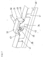
- FIG. 3 the transmission seat in the upper rail 40 is shown enlarged.
- the top rail 40 has on its upper Wall part via a recess 45 in which the box-shaped housing of the transmission 30 sits.
- the gear 30 is clamped in this recess 45.
- wall sections of the upper wall are bent by 90 ° inwardly into the recess 45 and serve as a stop lug 43.
- Two of these stop lugs 43 are located opposite one another in the longitudinal extent of the upper rail 40. These stop lugs 43 can be seen particularly clearly in FIG.
- the box-shaped housing of the transmission 30 sits between two mutually parallel wall portions 46 which extend integrally from the side walls of the upper rail 40 parallel upwards.
- the gear 30, which is formed from an upper housing part 31 and a lower housing part 32 and preferably made of plastic, between the two mentioned stop lugs 43 and the wall portions 46.
- the Betracher facing wall portion 46 is provided with an opening through which the flex shaft 50 protrudes into the interior of the housing of the transmission 30.
- Slotted bridges 41 are also pressed. These are wall sections which are pressed into the interior of the upper rail 40 by slots which are incorporated parallel to one another in the side walls of the upper rail 40. Each two such slotted bridges 41 are located directly opposite each other. These slot bridges 41 narrow the interior of the upper rail 40 and serve (see Fig. 9) as a stop for the upper housing part 31 and lower housing part 32 of the transmission 30. Furthermore, there is a recess 42 in the two side walls of the upper rail opposite, which between the respectively arranged slot bridges 41 is located. This recess 42 serves to partially receive a support disk 34 in a manner to be explained.
- the flex shaft 50 protrudes into the interior of the housing of the transmission 30 via a flexible shaft adapter 52. At the end of this flex shaft adapter 52 sits inside the gear 30, a worm 35 which is in engagement with a spindle nut 36.
- This spindle nut 36 is provided with a worm wheel.
- a support disk is integrally formed on this spindle nut with worm wheel in one piece.
- the spindle nut together with worm wheel and support disk are preferably made of metal.
- a washer 37 may be provided within the transmission 30.
- the existing of the lower housing part 32 and the upper housing part 31 housing of the transmission 30 is made of plastic and has box-like parts 31 a and 32 a, through which the spindle 14 is guided.
- the ends of these box-shaped parts 31a and 32a find their abutment on the aforementioned slot bridges 41.
- slot bridges 11 can also be incorporated into the bottom wall of the lower rail. These slot bridges 11 are likewise wall sections bent or pressed in the direction of the upper rail and, as shown in FIG. 9, are arranged in front of the respective end stops 18 opposite the fastening rivets 16.
- Fig. 9 clearly shows, in a crash, the axial acceleration of the seat occurring is intercepted both by the slot bridges 11 and 41 and by the support disk in cooperation with the recess in the upper rail 40.
- the slotted bridges 11 and 41 are arranged in pairs, so that no matter whether the acceleration goes forward or backward in the event of a crash, effective support of the adjustment of the seat adjustment is guaranteed.
- the support disk 34 interacts with the recess of the upper rail also during acceleration in the forward or backward direction, the force occurring.
- Fig. 9 is also also apparent that the end stops 18 are formed by U-shaped bracket.
- the spindle 14 projects through the longitudinal limbs of these U-shaped brackets, wherein retaining tabs are provided at the ends of these U-shaped bracket, through which the fastening rivets 16 are guided.
- FIG. 4 the device shown in Figs. 1-3 is shown cut in front view of the seat rail.
- the already explained reference numerals stand again for the known parts.
- the cross-sectionally U-shaped bottom rail 10 has inwardly bent back wall parts. Between these inwardly curved wall parts of the lower rail 10 protrude - seen from the side walls of the upper rail 40 - outwardly bent back wall parts of the upper rail 40.
- This design of the upper rail 40 and the lower rail 10 ensures that a lateral slippage of the upper rail 40 and lower rail 10 is excluded. In addition, a certain leadership is guaranteed.
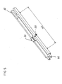
- Fig. 5 illustrates schematically the possible travel path between the upper rail and lower rail. In the present embodiment is provided as a possible travel 343mm.
- Fig. 6 shows in sectional view particularly clearly incorporated in the upper rail 40 slot bridges, which narrow the interior of the U-shaped upper rail significantly and thus serve as a stop for the transmission 30.
- FIG. 10 shows the upper rail 40 and the lower rail 10 together with the individual components described above in an exploded view.
- the already known components are provided with the same reference numerals as above.
- the laterally extending from the housing of the transmission 30 forth support disk 34 is Fig.11.
- the already explained Fig. 12 shows the transmission in an exploded view.
- the spindle nut 36 together with the worm wheel and integrally formed supporting disc 34 can be clearly seen.
- the worm 35 which is driven by the flex shaft, meshes with the worm wheel 37. By this drive, the transmission moves along the Sindel 14th
- FIG. 13 the gear without housing is again clearly shown, the sake of clarity, the Schnekke on the flex shaft 50 has been omitted.
- the flexshaft 50 is guided into the housing of the transmission via the already mentioned flexshaft adapter 52.
- a bayonet closure 60 together with clips 62 ensures that the flexible shaft is held in a suitable manner on the housing of the transmission 30.
- FIG. 16 individual representations are again shown in longitudinal section to illustrate the absorption of the crash forces. It should be noted that the recess 42 or cutout in the overlap 40 in the region of the support disk 34 is formed so that no contact between the support disk 34 and upper rail 40 prevails in the normally installed state. Only in the event of a crash, the support plate 34 is supported on the housing wall of the upper rail 40.
- the support disk 34 contacts the upper rail 40 in the event of a crash with a contact surface which is formed on the support disk 34 in the form of a pigment on the left and right.
- the support plate 34 is supported symmetrically on the left and right side walls of the upper rail 40 from.
Description
Die Erfindung betrifft eine Einrichtung für eine SitzlängsverStellung, insbesondere innerhalb eines Kfz, gemäß den Merkmalen des Oberbegriffs des Anspruchs 1.The invention relates to a device for a SitzlängsverStellung, especially within a motor vehicle, according to the features of the preamble of claim 1.
Solche Sitzlängsverstellungen sind zwischenzeitlich hinlänglich bekannt. Die Sitzlängsverstellungen weisen eine an einem Chassis festgelegte Unterschiene auf, innerhalb der eine Oberschiene, an der der Sitz befestigt ist, motorisch verfahrbar ist. Hierbei sitzt innerhalb der Oberschiene eine an der Unterschiene mit ihren jeweiligen Enden festgelegte Spindel, auf welcher ein mit der Oberschiene feststehend gekoppeltes Getriebe axial beweglich angeordnet ist. Der Sitz, der sich auf den beiden parallel zueinander angeordneten Oberschienen befindet-, kann über eine motorische Einrichtung, die zwischen den Schienen sitzt, verfahren werden.Such seat length adjustments are well known meantime. The seat-length adjusters have a lower rail fixed to a chassis, within which an upper rail to which the seat is fastened can be moved by a motor. In this case, sitting within the upper rail a fixed to the lower rail with their respective ends spindle on which a stationary with the upper rail coupled gear is arranged axially movable. The seat, which is located on the two mutually parallel upper rails, can be moved via a motor device that sits between the rails.
Beispiele für Einrichtungen zu Sitzlängsverstellungen sind in DE 36 40 197 A1, DE 42 08 948 C2, DE 196 42 655 C2, DE 198 15 283 A1, DE 198 44 817 A1, DE 199 44 690 A1 und WO 95/16 585 beschrieben worden.Examples of devices for seat-length adjustments have been described in
Der Erfindung liegt die Aufgabe zugrunde, eine kompakte Sitzlängsverstellungseinrichtung anzugeben, bei der nur wenige Bauteile notwendig sind und welche insbesondere im Falle eines Crashs die auftretenden Kräfte ohne weiteres aufnehmen kann. Hierbei soll das aufzufindende Getriebe zur Längsverstellung des Sitzes die Rotationsbewegung des Antriebsmotors in eine Translationsbewegung umwandeln.The invention has for its object to provide a compact seat-length adjustment device in which only a few components are necessary and which in particular in the event of a crash, the forces can easily absorb. Here, the aufzufindende gear for longitudinal adjustment of the seat to convert the rotational movement of the drive motor in a translational motion.
Eine weitere Aufgabe der vorliegenden Erfindung besteht darin, daß der Bauraum der Sitzlängsverstellungseinrichtung verhältnismäßig klein, vorzugsweise in der Breite nur 15 mm betragen soll. Darüber hinaus soll die zulässige Überragung der Oberschiene ebenfalls nicht allzu groß, maximal etwa 15 mm sein. Schließlich soll die erfindungsgemäße Einrichtung eine Festigkeitsforderung in beide Richtungen erfüllen, die bspw. 25000 N beträgt. Schließlich soll die erfindungsgemäße Einrichtung verhältnismäßig schnell, d. h. z. B. zwischen 15 und 25 mm/s über einen verhältnismäßig langen Verstellbereich von z. B. 300 mm verstellbar sein.Another object of the present invention is that the space of the seat longitudinal adjustment device should be relatively small, preferably only 15 mm in width. In addition, the allowable overhang of the top rail should also not be too large, at most about 15 mm. Finally, the device according to the invention should meet a strength requirement in both directions, for example, 25,000 N. is. Finally, the inventive device should be relatively fast, ie, for example, between 15 and 25 mm / s over a relatively long adjustment of z. B. 300 mm adjustable.
Diese Aufgabe wird durch eine Einrichtung mit den Merkmalen des Anspruchs 1 gelöst.This object is achieved by a device having the features of claim 1.
Weiterbildungen der Erfindung sind Gegenstand der hierauf bezogenen Unteransprüche.Further developments of the invention are the subject of the subclaims related thereto.
In einer bevorzugten Ausbildung der Erfindung wird die Rotationsbewegung des Motors über eine Flexwelle, eine Schnecke, eine Spindel und eine Spindelmutter in die Translationsbewegung umgewandelt.In a preferred embodiment of the invention, the rotational movement of the motor via a flex shaft, a worm, a spindle and a spindle nut is converted into the translational movement.
Zur Geräuschreduzierung empfiehlt es sich, die Spindel vorzugsweise exakt parallel zur Ober- und Unterschiene auszurichten.To reduce noise, it is advisable to align the spindle preferably exactly parallel to the top and bottom rail.
In einer anderen Weiterbildung der Erfindung ist mindestens eines der Wandteile der Oberschiene mit einer Ausnehmung versehen, durch welche eine mit einem Antriebsmotor gekoppelte Flexwelle geführt ist.In another embodiment of the invention, at least one of the wall parts of the upper rail is provided with a recess through which a flex shaft coupled to a drive motor is guided.
In einer weiteren Ausbildung der Erfindung sind Seitenwandungen der Oberschiene als Schlitzbrücken ausgebildet und in das Innere der Oberschiene gedrückt, wobei sich das Getriebegehäuse an diesen Schlitzbrücken abstützen kann.In a further embodiment of the invention, side walls of the upper rail are designed as slot bridges and pressed into the interior of the upper rail, wherein the gear housing can be supported on these slot bridges.
Das Getriebegehäuse besteht vorzugsweise aus zwei aus Kunststoff bestehenden Gehäuseschalen, welche durch Ultraschallverschweißung miteinander verbunden sind. Zweckmäßigerweise ist das Gehäuse, das durch Ultraschallverschweißung der beiden Gehäusehälften verbunden ist, nur auf Druckbelastung ausgelegt.The gear housing is preferably made of two plastic housing shells, which are interconnected by ultrasonic welding. Conveniently, the housing, which is connected by ultrasonic welding of the two housing halves, designed only to compressive load.
Eine klemmende Halterung des Getriebes wird erfindungsgemäß durch gegenüberliegend in eine Aussparung der Oberschiene eingearbeitete L-förmig gebogene Metallbügel erreicht, zwischen denen das Getriebegehäuse mit Wandschrägen eingeschoben wird.A clamping holder of the transmission is inventively incorporated by opposing in a recess of the upper rail L-shaped metal bracket is reached, between which the gear housing is inserted with sloping walls.
Die Spindelmutter und die oben erwähnte Stützscheibe, welche sich im Crashfall in Wandungen der Oberschiene abstützen kann, sind vorzugsweise einteilig bzw. einstückig ausgebildet. Beide bestehen bevorzugt aus Metall.The spindle nut and the above-mentioned support disk, which can be supported in the event of a crash in walls of the upper rail, are preferably formed in one piece or in one piece. Both are preferably made of metal.
In einer anderen Weiterbildung ist koaxial auf die Spindelmutter eine Schneckennaht durch Kunststoffspritzen aufgebracht.In another development coaxial with the spindle nut a worm seam is applied by plastic spraying.
Die Funktionsweise der Sitzlängsverstellung ist folgende. Das Getriebe wird in eine U-förmige Sitzschiene eingebaut. Diese Sitzschiene besteht aus einer Unter- und einer Oberschiene, wie oben erwähnt. Die Unterschiene ist mit der Fahrzeugkarosserie verbunden, während die Oberschiene mit dem Fahrzeugsitz verbunden ist. Das Getriebegehäuse wird über zwei Nasen mit der Oberschiene fixiert und bevorzugt mit einem Spannstift gesichert. Die Spindelmutter selbst ist über zwei Schrauben mit der Unterschiene verbunden. Über die Translationsbewegung der Spindel-Spindelmutterpaarung erfolgt die Verstellung des Sitzes. Zur Verstellung eines Sitzes werden zwei Schienen und damit zwei Getriebe (ein linkes und ein rechtes) benötigt.The operation of the seat length adjustment is the following. The gearbox is installed in a U-shaped seat rail. This seat rail consists of a lower and a top rail, as mentioned above. The lower rail is connected to the vehicle body while the upper rail is connected to the vehicle seat. The gear housing is fixed by two lugs with the top rail and preferably secured with a dowel pin. The spindle nut itself is connected to the bottom rail via two screws. About the translational movement of the spindle-spindle nut pairing, the adjustment of the seat. To adjust a seat two rails and thus two gears (one left and one right) are needed.
Die Hauptfunktion des Getriebes besteht in der Umwandlung der Rotationsbewegung in eine Translationsbewegung. Die Rotationsbewegung wird mittels eines Motors und der adaptierten Flexfälle über einen in der Getriebeschnecke integrierten Vierkant auf das Getriebe übertragen. Die Spindel wird über das umspritzte Schneckenrad mit einem definierten Übersetzungsverhältnis angetrieben. Die Umwandlung in die Translationsbewegung erfolgt über die Spindel-Spindelmutterpaarung. Beide Teile verfügen über ein Trapezgewinde.The main function of the gearbox is to convert the rotational movement into a translatory movement. The rotational movement is transmitted by means of a motor and the adapted Flexfälle over a built-in gear worm square on the gearbox. The spindle is driven by the over-molded worm wheel with a defined gear ratio. The conversion into the translational movement via the spindle-spindle nut pairing. Both parts have a trapezoidal thread.
Das erfindungsgemäße Getriebe zeichnet sich insbesondere dadurch aus, daß es im Crashfall sehr hohe Kräfte aufnehmen kann. Das Gehäuse des Getriebes ist selbst nicht in der Lage, die Kräfte bei einem Frontalcrash aufzunehmen. Solche Kräfte liegen bei etwa 24000 N. Im Crashfall wird bei dem erfindungegemäßen Getriebe das Gehäuse des Getriebes zerstört und die stützscheibe, die bevorzugt aus Metall besteht, kann beidseitig gegen die Kontaktflächen der Oberschiene anstoßen. Die Teile Oberschiene, Stützscheibe, Spindel, Spindelmutter und Unterschiene befinden sich bei der erfindungsgemäßen Einrichtung für eine Sitzlängsverstellung im Crashfall im Kraftfluß und können vorteilhafterweise die Crashkräfte aufnehmen.The transmission according to the invention is characterized in particular by the fact that it can absorb very high forces in the event of a crash. The housing of the transmission itself is not able to absorb the forces in a frontal crash. Such forces are about 24,000 N. In the event of a crash is in the erfindungegemäßen Gearbox destroyed the housing of the transmission and the support plate, which preferably consists of metal, can abut both sides against the contact surfaces of the upper rail. The parts upper rail, support disk, spindle, spindle nut and bottom rail are in the inventive device for a seat-length adjustment in the event of a crash in the power flow and can advantageously absorb the crash forces.
Die erfindungsgemäße Einrichtung für eine Sitzlängsverstellung zeichnet sich durch eine freie Positionierbarkeit der Getriebe auf der Schiene, der einstückigen Ausbildung Stützscheibe/Spindelmutter, eine drehende Mutter und eine drehende Spindel aus. Darüber hinaus ergibt sich mit der erfindungsgemäßen Einrichtung ein größerer Verfahrweg bei gleichen Einbaubedingungen.The inventive device for a seat-length adjustment is characterized by a free positioning of the gear on the rail, the integral formation support disk / spindle nut, a rotating nut and a rotating spindle. In addition, results with the device according to the invention a larger travel under the same installation conditions.
Darüber hinaus zeichnet sich die erfindungsgemäße Einrichtung bzw. das darin realisierte Getriebe durch folgende Merkmale aus.In addition, the device according to the invention or the gear realized therein is distinguished by the following features.
Der getriebetechnische Verstellantrieb besteht nur aus vier bzw. fünf Bauteilen. Die Verzahnungsteile des Schneckengetriebes werden in einem Kunststoffkäfig direkt gelagert. Auf gesonderte Lagerbauteile kann verzichtet werden. Die Käfigbestandteile werden durch Ultraschallverschweißung mit dem Hinblick auf spielfreie Funktion der Verzahnungsteile über einen individuellen Absenkweg verbunden und fixiert. Die Flexwellenanbindung ist integraler Bestandteil der Getriebefixierung an der Sitzschiene. Die Flexwellenanbindung stellt eine koaxiale Fixierung der rotierenden Flexwelle zur Antriebsschnecke sicher und wird vorzugsweise über eine Bajonettverbindung mit Schnappverschluß am Kunststoffkäfig befestigt.The gearbox adjustment consists of only four or five components. The gearing parts of the worm gear are stored directly in a plastic cage. Separate bearing components can be dispensed with. The cage components are connected and fixed by ultrasonic welding with regard to backlash-free function of the gearing parts via an individual Absenkweg. The flex shaft connection is an integral part of the gear fixing on the seat rail. The Flexwellenanbindung ensures a coaxial fixation of the rotating flex shaft to the drive screw and is preferably attached via a bayonet connection with snap closure on the plastic cage.
Der Getriebekäfig wird mittels Schlitzbrücken und Blechdurchzüge spielfrei aber elastisch mit der Sitzschiene verbunden und kann individuell im Montageprozeß angepaßt werden. Die Spindelmutter ist zugleich Schneckenrad und Stützscheibe. Die integrierte Stützscheibe entlastet im Falle eines Crashs das Kunststoffgetriebe von Crashkräften. Die Stützscheibe stützt sich dabei mittels Überstand an in der Sitzschiene angebrachter Ausnehmungen ab. Die Gewindespindel läßt sich für Montage und Raparaturzwecke nachträglich demontieren.The gear cage is connected without play by means of slot bridges and sheet metal passages but elastically connected to the seat rail and can be adapted individually in the assembly process. The spindle nut is at the same time worm wheel and support disk. The integrated support disc relieves the plastic transmission of crash forces in the event of a crash. The support disc supports itself by means of projection on in the seat rail mounted recesses. The threaded spindle can be subsequently dismantled for assembly and repair purposes.
Die erfindungsgemäße Einrichtung zur Sitzlängsverstellung wird nachfolgend im Zusammenhand mit mehreren Figuren anhand eines Ausführungsbeispieles näher erläutert. Es zeigen:
- Fig. 1
- eine perspektivische Darstellung der Unterschiene mit eingebauter Spindel sowie auf der Spindel sitzendem Getriebe in Draufsicht in perspektivischer Darstellung,
- Fig. 2
- eine perspektivische Darstellung der Schiene von Fig. 1 mit eingesetzter Oberschiene bzw. Sitzschiene,
- Fig. 3
- eine Detaildarstellung des in der Oberschiene gehaltenen Getriebes,
- Fig. 4
- eine Stirnansicht der in Fig. 2 und 3 dargestellten Anordnung in Stirnansicht,
- Fig. 5
- beispielhafte Maßangaben über den Verfahrweg der Oberschiene zur Unterschiene in mm,
- Fig. 6
- eine Detailansicht der Endanschlagüberdeckung,
- Fig. 7
- das Sitzschienenprofil im Getriebebereich,
- Fig. 8
- die Oberschienenansicht mit aufgebrochenem Gehäuse,
- Fig. 9
- eine Detaildarstellung der Getriebebefestigung zur Unterschiene,
- Fig. 10
- einen Vorschlag für eine Montagefolge der erfindungsgemäßen Einrichtung,
- Fig. 11
- der Bereich des Getriebes in vergrößerter Darstellung,
- Fig. 12
- das Getriebe in Explosionsansicht,
- Fig. 13
- eine Detailansicht des Flexwellenadapters,
- Fig. 14
- Detailansichten zur Erläuterung der Aufnahme der Crashkräfte bei der erfindungsgemäßen Einrichtung.
- Fig. 1
- a perspective view of the lower rail with built-in spindle and sitting on the spindle gear in plan view in perspective view,
- Fig. 2
- a perspective view of the rail of Figure 1 with inserted upper rail or seat rail,
- Fig. 3
- a detailed representation of the held in the upper rail transmission,
- Fig. 4
- an end view of the arrangement shown in FIGS. 2 and 3 in front view,
- Fig. 5
- exemplary dimensions of the travel path of the upper rail to the lower rail in mm,
- Fig. 6
- a detailed view of the end stop coverage,
- Fig. 7
- the seat rail profile in the transmission area,
- Fig. 8
- the top rail view with broken housing,
- Fig. 9
- a detailed view of the gearbox mounting to the bottom rail,
- Fig. 10
- a proposal for a mounting sequence of the device according to the invention,
- Fig. 11
- the area of the gearbox in an enlarged view,
- Fig. 12
- the gearbox in exploded view,
- Fig. 13
- a detailed view of the flexshaft adapter,
- Fig. 14
- Detailed views to explain the inclusion of the crash forces in the device according to the invention.
Wie aus Fig. 1 ersichtlich, sitzt innerhalb einer im Querschnitt U-förmigen Unterschiene 10, die endseitig über Befestigungsschrauben 12 am Chassis eines Fahrzeuges festgelegt ist, eine Spindel 14. Diese Spindel 14 ist an ihren beiden Enden über einen Endanschlag 18 in der Unterschiene 10 feststehend angeordnet. Die Verbindung zwischen Spindel 14 und Unterschiene 10 kann auf beliebige Weise erfolgen. Im dargestellten Ausführungsbeispiel ist diese Spindel 14 über ihre Endanschläge 18 mittels Befestigungsnieten 16 am Boden der Unterschiene 10 befestigt. An dem in Fig. 1 links dargestellten oberen Ende der Spindel 14 befindet sich eine Einstellmutter 20 und am rechts unten dargestellten Ende eine Anschlagmutter 22. Auf der Spindel ist ein Getriebe 30, das im Einzelnen noch erläutert werden wird, verfahrbar angeordnet. Das Getriebe 30 wird von einer Flexwelle 50 angetrieben. Bei rotierender Flexwelle 50 bewegt sich das Getriebe 30 auf der Spindel 14 nach links oder rechts, je nachdem, in welche Richtung die Flexwelle 50 dreht.As can be seen from FIG. 1, a
Mit dem Getriebe 30 ist feststehend eine Oberschiene 40 gekoppelt. Auf der Oberschiene 40 ist ein Sitz, bevorzugt ein Sitz eines Kraftfahrzeugs, befestigt. Die Unterschiene 10 samt Oberschiene 40 und Getriebe 30 sind parallel zueinander unter einem zu verstellenden Sitz angeordnet. Zwischen jeweils einem solchen Schienenpaar sitzt ein Antriebsmotor, welcher die Flexwelle 50 jedes Getriebes 30 antreibt, so daß der Sitz nach vorn oder hinten bewegt werden kann.An
In Fig. 3 ist der Getriebesitz in der Oberschiene 40 vergrößert dargestellt. Eine ähnliche Darstellung, jedoch von der anderen Seite her gesehen, mit weggelassener Unterschiene, zeigt Fig. 7. Die Oberschiene 40 verfügt auf ihrem oberen Wandteil über eine Ausnehmung 45, in der das kastenförmige Gehäuse des Getriebes 30 sitzt. Das Getriebe 30 wird klemmend in dieser Ausnehmung 45 gehalten. Hierfür sind Wandabschnitte der oberen Wandung um 90° nach innen in die Ausnehmung 45 gebogen und dienen als Anschlagnase 43. Zwei dieser Anschlagnasen 43 befinden sich gegenüberliegend in Längserstreckung der Oberschiene 40. Diese Anschlagnasen 43 sind besonders deutlich in Fig. 8 zu erkennen. Darüber hinaus sitzt das kastenförmige Gehäuse des Getriebes 30 zwischen zwei parallel zueinander liegenden Wandabschnitten 46, die sich einstückig von den Seitenwandungen der Oberschiene 40 parallel nach oben erstrecken. Damit sitzt das Getriebe 30, das aus einem Gehäuseoberteil 31 und einem Gehäuseunterteil 32 gebildet ist und bevorzugt aus Kunststoff besteht, zwischen den beiden erwähnten Anschlagnasen 43 und den Wandabschnitten 46. Der dem Betracher zugewandte Wandabschnitt 46 ist mit einer Öffnung versehen, durch welche die Flexwelle 50 in das Innere des Gehäuses des Getriebes 30 ragt.In Fig. 3, the transmission seat in the
In den Seitenwandungen der Oberschiene 40 sind darüber hinaus sog. Schlitzbrücken 41 eingedrückt. Hierbei handelt es sich um Wandabschnitte, welche durch parallel zueinander in die Seitenwarsdungen der Oberschiene 40 eingearbeitete Schlitze in das Innere der Oberschiene 40 gedrückt sind. Jeweils zwei solcher Schlitzbrücken 41 befinden sich direkt gegenüberliegend zueinander. Diese Schlitzbrücken 41 verengen den Innenraum der Oberschiene 40 und dienen (vgl. Fig. 9) als Anschlag für das Gehäuseoberteil 31 und Gehäuseunterteil 32 des Getriebes 30. Des weiteren befindet sich gegenüberliegend in den beiden Seitenwandungen der Oberschiene 40 eine Ausnehmung 42, welche zwischen den jeweils angeordneten Schlitzbrücken 41 liegt. Diese Ausnehmung 42 dient zur teilweisen Aufnahme einer Stützscheibe 34 in noch zu erläuternder Art und Weise.In the side walls of the
Die Flexwelle 50 ragt in das Innere des Gehäuses des Getriebes 30 über einen Flexwellenadapter 52. Am Ende dieses Flexwellenadapters 52 sitzt im Inneren des Getriebes 30 eine Schnecke 35, die mit einer Spindelmutter 36 in Eingriff steht. Diese Spindelmutter 36 ist mit einem Schneckenrad versehen. Wie insbesondere aus Fig. 12 besonders deutlich erkennbar, ist an diese Spindelmutter mit Schneckenrad einstöckig eine Stützscheibe angeformt. Die Spindelmutter samt Schneckenrad und Stützscheibe bestehen vorzugsweise aus Metall. Zusätzlich kann noch eine Unterlegscheibe 37 innerhalb des Getriebes 30 vorgesehen sein. Das aus dem Gehäuseunterteil 32 und dem Gehäuseoberteil 31 bestehende Gehäuse des Getriebes 30 besteht aus Kunststoff und verfügt über kastenartige Teile 31a und 32a, durch welche die Spindel 14 geführt ist. Die Enden dieser kastenförmigen Teile 31a und 32a finden an den erwähnten Schlitzbrücken 41 ihren Anschlag. Beim Verfahren des Getriebes durch Antrieb über die Flexwelle 50 wird insgesamt durch die beschriebene Anordnung des Getriebes und der Oberschiene die Oberschiene entlang der Spindel und damit innerhalb der Unterschiene 10 mitgenommen.The
Wie Fig. 9 zeigt, können auch in die Bodenwandung der Unterschiene Schlitzbrücken 11 eingearbeitet sein. Bei diesen Schlitzbrücken 11 handelt es sich ebenfalls um in Richtung Oberschiene gebogene bzw. eingedrückte Wandabschnitte, welche - wie Fig. 9 zeigt - vor den jeweiligen Endanschlägen 18 gegenüberliegend zu den Befestigungsnieten 16 angeordnet sind.As shown in FIG. 9, slot bridges 11 can also be incorporated into the bottom wall of the lower rail. These slot bridges 11 are likewise wall sections bent or pressed in the direction of the upper rail and, as shown in FIG. 9, are arranged in front of the respective end stops 18 opposite the fastening rivets 16.
Wie die Darstellung von Fig. 9 deutlich zeigt, wird in einem Crashfall die auftretende Axialbeschleunigung des Sitzes sowohl durch die Schlitzbrücken 11 und 41 als auch durch die Stützscheibe im Zusammenspiel mit der Ausnehmung in der Oberschiene 40 abgefangen. Hierbei sind die Schlitzbrücken 11 und 41 jeweils paarweise angeordnet, so daß gleichgültig, ob die Beschleunigung nach vorne oder hinten im Crashfall geht, ein wirksames Abstützen der Einstelleinrichtung der Sitzverstellung gewährleistet ist. Zusätzlich wirkt die Stützscheibe 34 im Zusammenspiel mit der Ausnehmung der Oberschiene ebenfalls bei Beschleunigung in Vorwärts- oder Rückwärterichtung die auftretende Kraft auf.As the illustration of Fig. 9 clearly shows, in a crash, the axial acceleration of the seat occurring is intercepted both by the slot bridges 11 and 41 and by the support disk in cooperation with the recess in the
Aus Fig. 9 ist darüber hinaus ebenfalls noch ersichtlich, daß die Endanschläge 18 durch U-förmige Bügel gebildet sind. Die Spindel 14 ragt durch die Längsschenkel dieser U-förmigen Bügel, wobei an den Enden dieser U-förmigen Bügel Haltelaschen vorgesehen sind, durch welche die Befestigungsnieten 16 geführt sind.From Fig. 9 is also also apparent that the end stops 18 are formed by U-shaped bracket. The
In Fig. 4 ist die in den Fig. 1-3 dargestellte Einrichtung in Stirnansicht der Sitzschiene geschnitten dargestellt. Die bereits erläuterten Bezugszeichen stehen wieder für die bekannten Teile. In der Darstellung von Fig. 4 ist besonders deutlich zu erkennen, daß die im Querschnitt U-förmig gestaltete Unterschiene 10 nach innen zurückgebogene Wandungsteile aufweist. Zwischen diese nach innen gebogenen Wandungsteile der Unterschiene 10 ragen - von den Seitenwandungen der Oberschiene 40 her gesehen - nach außen zurückgebogene Wandungsteile der Oberschiene 40. Durch diese Gestaltung der Oberschiene 40 und der Unterschiene 10 ist gewährleistet, daß ein seitliches Verrutschen der Oberschiene 40 und Unterschiene 10 ausgeschlossen ist. Darüber hinaus ist eine gewisse Führung gewährleistet.In Fig. 4, the device shown in Figs. 1-3 is shown cut in front view of the seat rail. The already explained reference numerals stand again for the known parts. In the illustration of Fig. 4 is particularly clearly seen that the cross-sectionally
Fig. 5 verdeutlicht schematisch den möglichen Verfahrweg zwischen Oberschiene und Unterschiene. Im vorliegenden Ausführungsbeispiel ist als möglicher Verfahrweg 343mm vorgesehen.Fig. 5 illustrates schematically the possible travel path between the upper rail and lower rail. In the present embodiment is provided as a possible travel 343mm.
Fig. 6 zeigt in Schnittansicht besonders deutlich die in die Oberschiene 40 eingearbeiteten Schlitzbrücken, die merklich den Innenraum in der U-förmig gestalteten Oberschiene verengen und somit als Anschlag für das Getriebe 30 dienen.Fig. 6 shows in sectional view particularly clearly incorporated in the
Fig. 10 zeigt die Oberschiene 40 und die Unterschiene 10 samt oben beschriebenen Einzelkomponenten in Explosionsdarstellung. Die bereits bekannten Komponenten sind mit den gleichen Bezugszeichen wie oben versehen.10 shows the
Im Fig. 11 ist das Getriebe 30 mit seinem Gehäuseunterteil 32 und dem Gehäuseoberteil 31 samt kastenförmiger, einstückig angeförmter Elemente im zusammangesetzen Zustand gezeigt. Auch in dieser Darstellung sind die von der oberen Wandung der Oberschiene 40 nach innen umgeklappten Anschlagnasen zu erkennen.In Fig. 11, the
Die seitlich sich von dem Gehäuse des Getriebes 30 hervor streckende Stützscheibe 34 zeigt Fig.11. Die bereits erläutete Fig. 12 zeigt das Getriebe in Explositionsansicht. Hier ist die Spindelmutter 36 samt Schneckenrad und einstückig angeförmter Stützscheibe 34 deutlich zu erkennen. Die Schnecke 35, die von der Flexwelle angetrieben wird, kämmt mit dem Schneckenrad 37. Durch diesen Antrieb bewegt sich das Getriebe entlang der Sindel 14.The laterally extending from the housing of the
In Fig. 13 ist das Getriebe ohne Gehäuse nochmals deutlich dargestellt, wobei der besseren Deutlichkeit wegen die Schnekke auf der Flexwelle 50 weggelassen wurde. Die Flexwelle 50 ist in über den bereits erwähnten Flexwellenadapter 52 in das Gehäuse des Getriebes geführt. Ein Bajonettverschluss 60 samt Clips 62 sorgt für eine geeignete Halterung der Flexwelle am Gehäuse des Getriebes 30. In Fig. 16 sind nochmals Einzeldarstellungen jeweils im Längsschnitt gezeigt, um die Aufnahme der Crashkräfte zu verdeutlichen. Hierbei ist anzumerken, das die Ausnehmung 42 bzw. Freisparung in der Überschiene 40 im Bereich der Stützscheibe 34 so ausgebildet ist, dass im normal eingebauten Zustand kein Kontakt zwischen Stützscheibe 34 und Oberschiene 40 herrscht. Erst im Crashfall stütz sich die Stützscheibe 34 an der Gehäusewandung der Oberschiene 40 ab.In Fig. 13, the gear without housing is again clearly shown, the sake of clarity, the Schnekke on the
Wie insbesondere aus der Darstellung oben rechts aus der Fig. 14 erkenntlich, berührt die Stützscheibe 34 die Oberschiene 40 im Crashfall mit eine Kontaktfläche, die sigmentförmig links und rechts an der Stützscheibe 34 sich ausgebildet ist. Damit stützt sich die Stützscheibe 34 symmetrisch an der linken und rechten Seitenwandung der Oberschiene 40 ab.As can be seen in particular from the illustration at the top right of FIG. 14, the
- 1010
- Unter-schieneUnder-rail
- 1111
- Schlitzbrückeslot bridge
- 1212
- Befestigungsschraubefixing screw
- 1414
- Spindelspindle
- 1616
- Befestigungsnietefixing rivet
- 1818
- Endanschlagend stop
- 2020
- Einstellmutteradjusting
- 2222
- Anschlagmutterstop nut
- 3030
- Getriebetransmission
- 3131
- GehäuseoberteilHousing top
- 3232
- GehäuseunterteilHousing bottom
- 3434
- Stützscheibesupport disc
- 3535
- Schneckeslug
- 3636
- Spindelmutterspindle nut
- 3737
- Schneckenradworm
- 3838
- Unterlegscheibewasher
- 4040
- Oberschieneupper rail
- 4141
- Schlitzbrückeslot bridge
- 4242
- Ausnehmungrecess
- 4343
- Anschlagnasestop lug
- 4545
- Ausnehmungrecess
- 4646
- Wandabschnitt, SeitenwandungWall section, side wall
- 5050
- Flexwelleflexshaft
- 5252
- FlexwellenadapterFlex shaft adapter
- 6060
- Bajonettverschlußbayonet
- 6262
- Clipsclips
- 31a31a
- Kastenförmiges TeilBox-shaped part
- 32a32a
- Kastenförmiges TeilBox-shaped part
Claims (10)
- Device for longitudinal seat adjustment, in particular within a motor vehicle, comprising a lower rail (10) which is fixed to a chassis and inside which an upper rail (40) to which a seat is attached can be displaced in a motor-driven manner, wherein seated within the upper rail (40) is a spindle (14) which is fixed by its respective ends to the lower rail (10), on which spindle a gear mechanism (30) is arranged such that it can move in the axial direction, said gear mechanism being fixedly coupled to the upper rail (40), characterised in that recesses (42) are provided in opposite side walls (46) of the upper rail (40), into which recesses there protrudes a supporting ring (34) which is fixed to the spindle (14) and which is seated with its main surface transverse to the longitudinal axis of the spindle (14) and which, in the event of a crash, is pressed against the side walls (46) of the upper rail (40).
- Device according to claim 1, characterised in that the gear mechanism (30) is tightly held in the upper rail (40) and has a gear mechanism housing, of which the opposite housing walls (46) lie between wall parts (46) of the upper rail (40) and the upper wall protrudes out of the upper rail (40).
- Device according to claim 1 or 2, characterised in that at least one of the wall parts (46) of the upper rail (40) has an opening (45), through which a flexible shaft (50) is passed, said flexible shaft being coupled to a drive motor.
- Device according to claim 1, 2 or 3, characterised in that side walls (46) of the upper rail have wall parts which are pressed into the interior of the upper rail (40), and in that the gear mechanism housing is supported on these wall parts.
- Device according to one of claims 1 to 4, characterised in that the gear mechanism housing comprises two housing shells (31, 32) made of plastic, which are joined to one another by ultrasonic welding.
- Device according to one of claims 1 to 5, characterised in that the tight holding of the gear mechanism (30) is achieved by means of opposite L-shaped metal clips inserted in a cutout of the upper rail (40), between which metal clips there is pushed the gear mechanism housing with bevelled walls.
- Device according to one of claims 1 to 6, characterised in that the gear mechanism (30) comprises a spindle nut (36) with a worm wheel (37) seated on the spindle (14) and a worm (35) meshing with the worm wheel (37).
- Device according to claim 7, characterised in that a supporting ring (34) is integrally formed on the spindle nut (36).
- Device according to claim 8, characterised in that the spindle nut (36) and the supporting ring (34) are made of metal.
- Device according to claim 8 or 9, characterised in that the worm wheel (37) is applied to the spindle nut (36) coaxially by means of plastic injection moulding.
Priority Applications (5)
| Application Number | Priority Date | Filing Date | Title |
|---|---|---|---|
| EP09010050A EP2123503B1 (en) | 2001-03-05 | 2002-03-05 | Device for horizontal adjustment of a seat, in particular inside a motor vehicle |
| EP07003473A EP1829735B1 (en) | 2001-03-05 | 2002-03-05 | Device for longitudinal seat adjustment, especially in a motor vehicle |
| EP09010063A EP2119590B1 (en) | 2001-03-05 | 2002-03-05 | Device for longitudinal seat adjustment, especially in a motor vehicle |
| EP09010062A EP2119589B1 (en) | 2001-03-05 | 2002-03-05 | Device for horizontal adjustment of a seat, in particular inside a motor vehicle |
| EP09010049A EP2123502B1 (en) | 2001-03-05 | 2002-03-05 | Device for horizontal adjustment of a seat, in particular inside a motor vehicle |
Applications Claiming Priority (3)
| Application Number | Priority Date | Filing Date | Title |
|---|---|---|---|
| DE10110245 | 2001-03-05 | ||
| DE10110245 | 2001-03-05 | ||
| PCT/EP2002/002396 WO2002070299A1 (en) | 2001-03-05 | 2002-03-05 | Longitudinal seat adjustment device, especially in a motor vehicle |
Related Child Applications (3)
| Application Number | Title | Priority Date | Filing Date |
|---|---|---|---|
| EP07003473A Division EP1829735B1 (en) | 2001-03-05 | 2002-03-05 | Device for longitudinal seat adjustment, especially in a motor vehicle |
| EP09010049A Division EP2123502B1 (en) | 2001-03-05 | 2002-03-05 | Device for horizontal adjustment of a seat, in particular inside a motor vehicle |
| EP09010050A Division EP2123503B1 (en) | 2001-03-05 | 2002-03-05 | Device for horizontal adjustment of a seat, in particular inside a motor vehicle |
Publications (2)
| Publication Number | Publication Date |
|---|---|
| EP1365939A1 EP1365939A1 (en) | 2003-12-03 |
| EP1365939B1 true EP1365939B1 (en) | 2007-05-16 |
Family
ID=7676176
Family Applications (6)
| Application Number | Title | Priority Date | Filing Date |
|---|---|---|---|
| EP07003473A Expired - Lifetime EP1829735B1 (en) | 2001-03-05 | 2002-03-05 | Device for longitudinal seat adjustment, especially in a motor vehicle |
| EP02722179A Expired - Lifetime EP1365939B1 (en) | 2001-03-05 | 2002-03-05 | Longitudinal seat adjustment device, especially in a motor vehicle |
| EP09010049A Expired - Lifetime EP2123502B1 (en) | 2001-03-05 | 2002-03-05 | Device for horizontal adjustment of a seat, in particular inside a motor vehicle |
| EP09010062A Expired - Lifetime EP2119589B1 (en) | 2001-03-05 | 2002-03-05 | Device for horizontal adjustment of a seat, in particular inside a motor vehicle |
| EP09010050A Expired - Lifetime EP2123503B1 (en) | 2001-03-05 | 2002-03-05 | Device for horizontal adjustment of a seat, in particular inside a motor vehicle |
| EP09010063A Expired - Lifetime EP2119590B1 (en) | 2001-03-05 | 2002-03-05 | Device for longitudinal seat adjustment, especially in a motor vehicle |
Family Applications Before (1)
| Application Number | Title | Priority Date | Filing Date |
|---|---|---|---|
| EP07003473A Expired - Lifetime EP1829735B1 (en) | 2001-03-05 | 2002-03-05 | Device for longitudinal seat adjustment, especially in a motor vehicle |
Family Applications After (4)
| Application Number | Title | Priority Date | Filing Date |
|---|---|---|---|
| EP09010049A Expired - Lifetime EP2123502B1 (en) | 2001-03-05 | 2002-03-05 | Device for horizontal adjustment of a seat, in particular inside a motor vehicle |
| EP09010062A Expired - Lifetime EP2119589B1 (en) | 2001-03-05 | 2002-03-05 | Device for horizontal adjustment of a seat, in particular inside a motor vehicle |
| EP09010050A Expired - Lifetime EP2123503B1 (en) | 2001-03-05 | 2002-03-05 | Device for horizontal adjustment of a seat, in particular inside a motor vehicle |
| EP09010063A Expired - Lifetime EP2119590B1 (en) | 2001-03-05 | 2002-03-05 | Device for longitudinal seat adjustment, especially in a motor vehicle |
Country Status (6)
| Country | Link |
|---|---|
| US (2) | US7198243B2 (en) |
| EP (6) | EP1829735B1 (en) |
| CN (1) | CN100343087C (en) |
| DE (2) | DE50210159D1 (en) |
| ES (6) | ES2393723T3 (en) |
| WO (1) | WO2002070299A1 (en) |
Cited By (1)
| Publication number | Priority date | Publication date | Assignee | Title |
|---|---|---|---|---|
| DE202010014396U1 (en) | 2010-10-16 | 2012-01-17 | Kiekert Ag | Drive unit for a motor vehicle door closing device |
Families Citing this family (45)
| Publication number | Priority date | Publication date | Assignee | Title |
|---|---|---|---|---|
| DE10353245A1 (en) * | 2003-11-13 | 2005-06-16 | Brose Fahrzeugteile Gmbh & Co. Kg, Coburg | Crash load absorption mechanism for adjustable automotive seat has gear mechanism located in the vicinity of a crash deformation zone |
| EP1571034B1 (en) * | 2004-03-04 | 2007-10-17 | KEIPER GmbH & Co. KG | Longitudinal adjuster for a vehicle seat |
| DE102004043630C5 (en) * | 2004-09-07 | 2011-08-18 | Johnson Controls GmbH, 51399 | Adjustment device, in particular for the seat of a vehicle |
| DE102004063932B4 (en) | 2004-09-21 | 2013-03-28 | Ims Gear Gmbh | Transmission and vehicle seat with such a transmission |
| JP4736566B2 (en) * | 2005-06-27 | 2011-07-27 | アイシン精機株式会社 | Vehicle seat slide device |
| DE102005060799B3 (en) | 2005-12-16 | 2007-06-21 | Ims Gear Gmbh | Gearing mechanism for adjusting two vehicle seat parts adjusted towards each other, especially vehicle seat adjusting device, window winder or sliding roof, has a fixed spindle and toothed rack |
| MX2008012292A (en) * | 2006-03-27 | 2009-02-10 | Johnson Controls Tech Co | Transmission device for seat adjuster. |
| DE102006052936A1 (en) * | 2006-11-08 | 2008-05-15 | Ims Gear Gmbh | Longitudinal adjustment unit for seats, especially in motor vehicles |
| FR2910393B1 (en) | 2006-12-20 | 2009-08-07 | Faurecia Sieges Automobile | SLIDER FOR A VEHICLE SEAT, SLIDER SYSTEM, SEAT COMPRISING SUCH A SLIDER AND A SEAT COMPRISING SUCH A SYSTEM |
| JP5194515B2 (en) | 2007-03-29 | 2013-05-08 | アイシン精機株式会社 | Driving device for power seat device for vehicle |
| DE102007018101A1 (en) * | 2007-04-16 | 2008-10-23 | Faurecia Autositze Gmbh | Vehicle seat, in particular motor vehicle seat |
| KR100892494B1 (en) | 2007-10-05 | 2009-04-10 | 현대자동차주식회사 | Apparatus for Adjusting a Length of Seat Cushion |
| FR2928880B1 (en) * | 2008-03-20 | 2011-02-11 | Faurecia Sieges Automobile | VEHICLE SEAT BASE AND VEHICLE SEAT COMPRISING SUCH BASE |
| DE202009001847U1 (en) | 2009-02-11 | 2010-07-01 | Brose Fahrzeugteile Gmbh & Co. Kommanditgesellschaft, Coburg | Spindle drive for a seat-length adjustment of a motor vehicle seat |
| US8540203B2 (en) * | 2009-12-16 | 2013-09-24 | Keiper Gmbh & Co. Kg | Longitudinal adjuster for a vehicle seat with spindle and spindle holder |
| CN101767546B (en) * | 2010-02-10 | 2012-02-29 | 苏州忠明祥和精工有限公司 | Sliding rail for automotive power seat |
| DE102010001844B4 (en) * | 2010-02-11 | 2023-06-01 | Brose Fahrzeugteile SE & Co. Kommanditgesellschaft, Coburg | spindle gear |
| KR101441027B1 (en) * | 2010-02-11 | 2014-09-17 | 브로제 파르쪼이크타일레 게엠베하 운트 코. 카게, 코부르크 | Adjusting device having an adjusting mechanism arranged on a guide rail |
| FR2959969B1 (en) * | 2010-05-17 | 2012-07-20 | Faurecia Sieges Automobile | SLIDE FOR VEHICLE SEAT AND VEHICLE SEAT COMPRISING SUCH A SLIDER |
| DE102010042008B4 (en) * | 2010-10-05 | 2021-09-02 | Adient Luxembourg Holding S.À R.L. | Longitudinal adjustment device for a motor vehicle seat |
| WO2012130574A2 (en) * | 2011-03-31 | 2012-10-04 | Johnson Controls Gmbh | Electrically driven longitudinal adjustment device for a vehicle seat |
| DE102011085873A1 (en) * | 2011-11-07 | 2013-05-08 | C. Rob. Hammerstein Gmbh & Co. Kg | Adjusting gear, in particular for seat-length adjustment of a motor vehicle seat |
| US10137803B2 (en) * | 2015-03-20 | 2018-11-27 | Adient Luxembourg Holding S.à.r.l. | Longitudinal adjustment mechanism for a vehicle seat |
| JP2018509338A (en) * | 2015-03-24 | 2018-04-05 | アディエント ルクセンブルク ホールディング エス エー アール エル | Adjusting device for vehicle seat and vehicle seat |
| US10843591B2 (en) | 2016-01-19 | 2020-11-24 | Fisher & Company, Incorporated | Gear assembly for a seat adjuster |
| US11273506B2 (en) | 2016-09-08 | 2022-03-15 | Fisher & Company, Incorporated | Open architecture power length adjuster assembly for a vehicle seat and method of manufacturing the same |
| US11766956B2 (en) | 2016-09-08 | 2023-09-26 | Fisher & Company, Incorporated | Open architecture power length adjuster assembly for a vehicle seat and method of manufacturing the same |
| US10953772B2 (en) | 2016-09-08 | 2021-03-23 | Fisher & Company, Incorporated | Open architecture power length adjuster assembly for a vehicle seat and method of manufacturing the same |
| CN106427675A (en) * | 2016-12-01 | 2017-02-22 | 广东东箭汽车用品制造有限公司 | Seat driving device and automobile seat |
| DE102017101996A1 (en) * | 2017-02-01 | 2018-08-02 | Ims Gear Se & Co. Kgaa | Adjustment device for adjusting a vehicle seat along a displacement axis |
| CN108725267B (en) * | 2017-04-19 | 2022-04-15 | 安道拓工程技术知识产权有限公司 | Longitudinal adjuster for a vehicle seat |
| WO2019201509A1 (en) * | 2018-04-19 | 2019-10-24 | Fisher Dynamics Germany Gmbh | Actuating drive for a motor vehicle, comprising an electric motor, a transmission, and a spindle |
| DE202018102446U1 (en) | 2018-05-02 | 2018-06-04 | Faurecia Autositze Gmbh | Linear actuator for a motor vehicle seat |
| JP2020082782A (en) * | 2018-11-16 | 2020-06-04 | シロキ工業株式会社 | Slide device |
| DE112020000364T5 (en) | 2019-01-09 | 2021-10-07 | Fisher & Company, Incorporated | POWERED SEAT RAIL ARRANGEMENT |
| US11760233B2 (en) | 2019-02-20 | 2023-09-19 | Fisher & Company, Incorporated | Ultra-compact power length adjuster with anti-back drive capability and pinion-rack output for a vehicle seat |
| CN110361593B (en) * | 2019-07-16 | 2021-08-10 | 国网山东省电力公司招远市供电公司 | Distribution network line loss analyzer |
| US11167664B2 (en) * | 2020-04-08 | 2021-11-09 | Adient Engineering and IP GmbH | Safety device |
| US11485255B2 (en) | 2020-05-01 | 2022-11-01 | Fisher & Company, Incorporated | Gearbox for vehicle seat adjustment mechanism |
| US11529892B2 (en) * | 2020-05-01 | 2022-12-20 | Fisher & Company, Incorporated | Gearbox for vehicle seat adjustment mechanism |
| US11904732B2 (en) | 2020-11-09 | 2024-02-20 | Ford Global Technologies, Llc | Vehicular system capable of adjusting a passenger compartment from a first arrangement to a child care arrangement |
| US11772519B2 (en) | 2020-11-09 | 2023-10-03 | Ford Global Technologies, Llc | Vehicular system capable of adjusting a passenger compartment from a first arrangement to a child seat arrangement |
| US11772517B2 (en) | 2020-11-09 | 2023-10-03 | Ford Global Technologies, Llc | Vehicular system capable of adjusting a passenger compartment from a child seat arrangement to a second arrangement |
| US11731535B2 (en) | 2020-11-09 | 2023-08-22 | Ford Global Technologies, Llc | Vehicular system capable of adjusting a passenger compartment from a child care arrangement to a second arrangement |
| US11772520B2 (en) | 2020-11-09 | 2023-10-03 | Ford Global Technologies, Llc | Remote notification and adjustment of a passenger compartment arrangement |
Family Cites Families (37)
| Publication number | Priority date | Publication date | Assignee | Title |
|---|---|---|---|---|
| US4245687A (en) * | 1979-05-30 | 1981-01-20 | Hunter Douglas International N.V. | Venetian blind and tilting mechanism therefor |
| JPS60127238U (en) * | 1984-02-06 | 1985-08-27 | アイシン精機株式会社 | Power type seat longitudinal adjustment device |
| JPS6276037U (en) | 1985-10-31 | 1987-05-15 | ||
| JPS62127545A (en) | 1985-11-26 | 1987-06-09 | Aisin Seiki Co Ltd | Driving device for power sheet |
| JPH0732249Y2 (en) * | 1990-05-29 | 1995-07-26 | 池田物産株式会社 | Power seat slide device |
| JPH0712153Y2 (en) * | 1990-09-26 | 1995-03-22 | 池田物産株式会社 | Power seat slide device |
| JP3089680B2 (en) | 1991-03-20 | 2000-09-18 | アイシン精機株式会社 | Vehicle seat slide device |
| JPH04115934U (en) * | 1991-03-28 | 1992-10-15 | 池田物産株式会社 | power seat sliding device |
| US5303983A (en) * | 1992-04-30 | 1994-04-19 | Itt Corporation | Rotatable seat belt buckle mounting bracket for vehicle seat adjuster |
| DE4227846C1 (en) * | 1992-08-22 | 1993-09-23 | Keiper Recaro Gmbh & Co, 42855 Remscheid, De | Lengthwise adjustment for car seat - has spindle and nut threads overcoming self-locking effect with rotary component braked by roller-type freewheel |
| NO932534L (en) * | 1993-07-12 | 1995-01-13 | Norsk Hydro As | A system for locking and adjusting car seats |
| FR2711100B1 (en) * | 1993-10-14 | 1995-12-15 | Bfa | Improvements to vehicle seat adjustment devices. |
| US5467957A (en) | 1993-12-15 | 1995-11-21 | Itt Corporation | Vehicle power seat adjuster with self-aligning drive nut |
| US5685930A (en) * | 1995-03-31 | 1997-11-11 | Davidson Textron Inc. | Motor vehicle instrument panel with flexible tethering hinged air bag deployment door |
| DE19513707C2 (en) * | 1995-04-11 | 1998-03-19 | Keiper Recaro Gmbh Co | Pair of rails for motor vehicle seats |
| JP3400613B2 (en) * | 1995-06-28 | 2003-04-28 | アイシン精機株式会社 | Vehicle seat slide device |
| DE29513272U1 (en) * | 1995-08-18 | 1997-01-02 | Bosch Gmbh Robert | Device for adjusting a seat in a motor vehicle |
| JP3501431B2 (en) * | 1995-10-31 | 2004-03-02 | 株式会社タチエス | Long slide rail |
| US5709363A (en) * | 1996-03-01 | 1998-01-20 | Tachi-S Co., Ltd. | Structure of powered seat |
| US5882075A (en) * | 1996-05-07 | 1999-03-16 | Lear Corporation | Power seat drive system |
| US5746409A (en) | 1996-07-19 | 1998-05-05 | Excellence Manufacturing, Inc. | Reinforced seat track |
| CN2278610Y (en) * | 1996-10-14 | 1998-04-15 | 中外合资常州华阳汽车附件有限公司 | Automotive seat moving locking device |
| DE19642655C1 (en) | 1996-10-16 | 1998-06-10 | Continental Ag | Reinforcement layer for the belt of a vehicle tire |
| US6000757A (en) * | 1997-08-14 | 1999-12-14 | Track Corp. | Vehicle seat adjuster |
| DE19815283C2 (en) * | 1998-04-06 | 2000-07-13 | Brose Fahrzeugteile | Spindle drive for adjustment devices in motor vehicles |
| DE19912978A1 (en) | 1998-08-12 | 2000-02-17 | Hammerstein Gmbh C Rob | Vehicle seat with adjustment device, which has a spindle and an associated spindle nut |
| EP0979750A3 (en) | 1998-08-12 | 2001-04-11 | C. Rob. Hammerstein GmbH & Co.KG | Vehicle seat adjusting device with a spindle and a spindle nut |
| US6032550A (en) * | 1998-09-08 | 2000-03-07 | Owens-Brockway Glass Container Inc. | Right angle drive gearbox |
| JP3656432B2 (en) | 1998-09-17 | 2005-06-08 | 日産自動車株式会社 | Power seat slide rail structure |
| DE19844817C2 (en) | 1998-09-30 | 2002-05-08 | Faurecia Autositze Gmbh & Co | Longitudinally adjustable motor vehicle seat |
| DE10230514B4 (en) * | 2002-07-06 | 2004-10-14 | Keiper Gmbh & Co. Kg | Longitudinal adjuster for a vehicle seat, in particular for a motor vehicle seat |
| DE102004013009B4 (en) * | 2004-03-16 | 2008-03-20 | Ims Gear Gmbh | Drive for an adjusting device within a vehicle, in particular a seat adjustment device within a motor vehicle and method for producing such a drive |
| JP4857558B2 (en) * | 2004-12-21 | 2012-01-18 | アイシン精機株式会社 | Power seat slide device for vehicle |
| FR2882974B1 (en) * | 2005-03-14 | 2008-11-07 | Faurecia Sieges Automobile | SCREW ADJUSTING MECHANISM, SLIDER COMPRISING SUCH AN ADJUSTING MECHANISM AND SEAT COMPRISING SUCH A SLIDER |
| JP4521638B2 (en) * | 2005-03-22 | 2010-08-11 | 株式会社今仙電機製作所 | Seat rail device |
| JP4661316B2 (en) * | 2005-04-08 | 2011-03-30 | アイシン精機株式会社 | Power seat slide device for vehicle |
| US7950616B2 (en) * | 2005-11-23 | 2011-05-31 | Ims Gear Gmbh | Form fitting connection between spindle and spindle holder of SLV gear |
-
2002
- 2002-03-05 DE DE50210159T patent/DE50210159D1/en not_active Expired - Lifetime
- 2002-03-05 ES ES09010049T patent/ES2393723T3/en not_active Expired - Lifetime
- 2002-03-05 ES ES09010063T patent/ES2404664T3/en not_active Expired - Lifetime
- 2002-03-05 EP EP07003473A patent/EP1829735B1/en not_active Expired - Lifetime
- 2002-03-05 ES ES02722179T patent/ES2284855T3/en not_active Expired - Lifetime
- 2002-03-05 EP EP02722179A patent/EP1365939B1/en not_active Expired - Lifetime
- 2002-03-05 WO PCT/EP2002/002396 patent/WO2002070299A1/en active IP Right Grant
- 2002-03-05 EP EP09010049A patent/EP2123502B1/en not_active Expired - Lifetime
- 2002-03-05 ES ES07003473T patent/ES2328286T3/en not_active Expired - Lifetime
- 2002-03-05 CN CNB028058992A patent/CN100343087C/en not_active Expired - Fee Related
- 2002-03-05 EP EP09010062A patent/EP2119589B1/en not_active Expired - Lifetime
- 2002-03-05 EP EP09010050A patent/EP2123503B1/en not_active Expired - Lifetime
- 2002-03-05 ES ES09010050T patent/ES2393724T3/en not_active Expired - Lifetime
- 2002-03-05 US US10/471,226 patent/US7198243B2/en not_active Expired - Lifetime
- 2002-03-05 ES ES09010062T patent/ES2387559T3/en not_active Expired - Lifetime
- 2002-03-05 EP EP09010063A patent/EP2119590B1/en not_active Expired - Lifetime
- 2002-03-05 DE DE50213753T patent/DE50213753D1/en not_active Expired - Lifetime
-
2006
- 2006-12-08 US US11/608,365 patent/US7484787B2/en not_active Expired - Fee Related
Cited By (1)
| Publication number | Priority date | Publication date | Assignee | Title |
|---|---|---|---|---|
| DE202010014396U1 (en) | 2010-10-16 | 2012-01-17 | Kiekert Ag | Drive unit for a motor vehicle door closing device |
Also Published As
| Publication number | Publication date |
|---|---|
| CN100343087C (en) | 2007-10-17 |
| EP2123503B1 (en) | 2012-08-29 |
| ES2393723T3 (en) | 2012-12-27 |
| US20070096494A1 (en) | 2007-05-03 |
| EP2123502A1 (en) | 2009-11-25 |
| EP1365939A1 (en) | 2003-12-03 |
| ES2328286T3 (en) | 2009-11-11 |
| EP2119590B1 (en) | 2013-02-27 |
| DE50210159D1 (en) | 2007-07-05 |
| US7198243B2 (en) | 2007-04-03 |
| WO2002070299A1 (en) | 2002-09-12 |
| ES2404664T3 (en) | 2013-05-28 |
| EP2123503A8 (en) | 2010-06-30 |
| EP1829735A1 (en) | 2007-09-05 |
| EP2123502A8 (en) | 2010-06-30 |
| DE50213753D1 (en) | 2009-09-17 |
| EP2119590A1 (en) | 2009-11-18 |
| CN1494496A (en) | 2004-05-05 |
| EP2119589A1 (en) | 2009-11-18 |
| ES2284855T3 (en) | 2007-11-16 |
| EP2123502B1 (en) | 2012-08-22 |
| US20040108436A1 (en) | 2004-06-10 |
| EP1829735B1 (en) | 2009-08-05 |
| EP2119589B1 (en) | 2012-06-06 |
| US7484787B2 (en) | 2009-02-03 |
| ES2393724T3 (en) | 2012-12-27 |
| ES2387559T3 (en) | 2012-09-26 |
| EP2123503A1 (en) | 2009-11-25 |
Similar Documents
| Publication | Publication Date | Title |
|---|---|---|
| EP1365939B1 (en) | Longitudinal seat adjustment device, especially in a motor vehicle | |
| DE19861100B4 (en) | Spindle or worm drive for adjustment devices in motor vehicles | |
| EP1068093B1 (en) | Spindle or worm drive for adjusting devices in motor vehicles | |
| DE10358586B4 (en) | Transmission housing of a Sitzverstellgetriebes for a motor vehicle | |
| EP2611647B1 (en) | Adjustment drive for adjustment devices of a motor vehicle seat | |
| EP1791717B1 (en) | Adjusting device, in particular for the seat of a motor vehicle | |
| DE112010005253B4 (en) | Adjusting device with an adjusting gear arranged on a guide rail and method for assembling an adjusting device | |
| DE102012013979A1 (en) | Linaearaktuator and method for producing a linear actuator | |
| WO1998048667A2 (en) | Drive mechanism for adjusting parts in furniture for sitting and lying down | |
| WO2013068000A1 (en) | Adjusting mechanism, in particular for longitudinally adjusting a motor vehicle seat | |
| WO2021023893A1 (en) | Door drive apparatus having a gear assembly comprising a guide rail | |
| DE102018117927B4 (en) | vehicle seat | |
| EP1493634A1 (en) | Airbag module with housing for the reception of at least one gas generator and at least one air bag | |
| DE102022104146A1 (en) | STEERING DEVICE | |
| DE19861276B4 (en) | Spindle or worm drive for adjusting devices in motor vehicles | |
| EP1545269A1 (en) | Electromotive furniture drive | |
| DE10361874B4 (en) | Device for adjusting a motor vehicle part | |
| EP3665038B1 (en) | Longitudinal adjuster for a vehicle seat | |
| DE19861278B4 (en) | Spindle or worm drive for adjusting mechanisms in motor vehicles has push-in connections for plates forming housing of mechanism and constructed as supporting connection points taking gearing forces | |
| DE10300942B3 (en) | Mechanical setting device for holder for automobile external rear view mirror with ratchet device for locking mirror holder in required position | |
| DE19925741A1 (en) | Actuator | |
| DE10045806A1 (en) | Position adjusting system for car seat comprises rails which slide inside each other and which can be adjusted by screw spindle which has integral flange with connecting sections allowing it to be attached to mounting on lower rail | |
| EP4100279A1 (en) | Longitudinal adjuster and vehicle seat | |
| EP4144615A1 (en) | Actuator, steering column for a motor vehicle and method for manufacturing and / or mounting an actuator | |
| EP4349688A1 (en) | Steering column for a motor vehicle |
Legal Events
| Date | Code | Title | Description |
|---|---|---|---|
| PUAI | Public reference made under article 153(3) epc to a published international application that has entered the european phase |
Free format text: ORIGINAL CODE: 0009012 |
|
| 17P | Request for examination filed |
Effective date: 20030730 |
|
| AK | Designated contracting states |
Kind code of ref document: A1 Designated state(s): AT BE CH CY DE DK ES FI FR GB GR IE IT LI LU MC NL PT SE TR |
|
| AX | Request for extension of the european patent |
Extension state: AL LT LV MK RO SI |
|
| GRAP | Despatch of communication of intention to grant a patent |
Free format text: ORIGINAL CODE: EPIDOSNIGR1 |
|
| RBV | Designated contracting states (corrected) |
Designated state(s): DE ES FR GB IT |
|
| GRAS | Grant fee paid |
Free format text: ORIGINAL CODE: EPIDOSNIGR3 |
|
| GRAA | (expected) grant |
Free format text: ORIGINAL CODE: 0009210 |
|
| AK | Designated contracting states |
Kind code of ref document: B1 Designated state(s): DE ES FR GB IT |
|
| REG | Reference to a national code |
Ref country code: GB Ref legal event code: FG4D Free format text: NOT ENGLISH |
|
| REF | Corresponds to: |
Ref document number: 50210159 Country of ref document: DE Date of ref document: 20070705 Kind code of ref document: P |
|
| ET | Fr: translation filed | ||
| REG | Reference to a national code |
Ref country code: ES Ref legal event code: FG2A Ref document number: 2284855 Country of ref document: ES Kind code of ref document: T3 |
|
| GBV | Gb: ep patent (uk) treated as always having been void in accordance with gb section 77(7)/1977 [no translation filed] |
Effective date: 20070516 |
|
| PLBE | No opposition filed within time limit |
Free format text: ORIGINAL CODE: 0009261 |
|
| STAA | Information on the status of an ep patent application or granted ep patent |
Free format text: STATUS: NO OPPOSITION FILED WITHIN TIME LIMIT |
|
| 26N | No opposition filed |
Effective date: 20080219 |
|
| PG25 | Lapsed in a contracting state [announced via postgrant information from national office to epo] |
Ref country code: GB Free format text: LAPSE BECAUSE OF FAILURE TO SUBMIT A TRANSLATION OF THE DESCRIPTION OR TO PAY THE FEE WITHIN THE PRESCRIBED TIME-LIMIT Effective date: 20070516 |
|
| REG | Reference to a national code |
Ref country code: FR Ref legal event code: PLFP Year of fee payment: 15 |
|
| REG | Reference to a national code |
Ref country code: DE Ref legal event code: R082 Ref document number: 50210159 Country of ref document: DE Representative=s name: WESTPHAL, MUSSGNUG & PARTNER PATENTANWAELTE MI, DE Ref country code: DE Ref legal event code: R081 Ref document number: 50210159 Country of ref document: DE Owner name: IMS GEAR SE & CO. KGAA, DE Free format text: FORMER OWNER: IMS GEAR GMBH, 78166 DONAUESCHINGEN, DE |
|
| REG | Reference to a national code |
Ref country code: ES Ref legal event code: PC2A Owner name: IMS GEAR SE & CO. KGAA Effective date: 20161216 |
|
| REG | Reference to a national code |
Ref country code: FR Ref legal event code: PLFP Year of fee payment: 16 |
|
| REG | Reference to a national code |
Ref country code: FR Ref legal event code: CD Owner name: IMS GEAR SE & CO. KGAA, DE Effective date: 20171013 Ref country code: FR Ref legal event code: CJ Effective date: 20171013 |
|
| REG | Reference to a national code |
Ref country code: FR Ref legal event code: PLFP Year of fee payment: 17 |
|
| PGFP | Annual fee paid to national office [announced via postgrant information from national office to epo] |
Ref country code: IT Payment date: 20200325 Year of fee payment: 19 |
|
| PGFP | Annual fee paid to national office [announced via postgrant information from national office to epo] |
Ref country code: FR Payment date: 20200325 Year of fee payment: 19 |
|
| PGFP | Annual fee paid to national office [announced via postgrant information from national office to epo] |
Ref country code: DE Payment date: 20200428 Year of fee payment: 19 Ref country code: ES Payment date: 20200421 Year of fee payment: 19 |
|
| REG | Reference to a national code |
Ref country code: DE Ref legal event code: R119 Ref document number: 50210159 Country of ref document: DE |
|
| PG25 | Lapsed in a contracting state [announced via postgrant information from national office to epo] |
Ref country code: FR Free format text: LAPSE BECAUSE OF NON-PAYMENT OF DUE FEES Effective date: 20210331 Ref country code: DE Free format text: LAPSE BECAUSE OF NON-PAYMENT OF DUE FEES Effective date: 20211001 |
|
| PG25 | Lapsed in a contracting state [announced via postgrant information from national office to epo] |
Ref country code: IT Free format text: LAPSE BECAUSE OF NON-PAYMENT OF DUE FEES Effective date: 20210305 |
|
| REG | Reference to a national code |
Ref country code: ES Ref legal event code: FD2A Effective date: 20220517 |
|
| PG25 | Lapsed in a contracting state [announced via postgrant information from national office to epo] |
Ref country code: ES Free format text: LAPSE BECAUSE OF NON-PAYMENT OF DUE FEES Effective date: 20210306 |