EP1365522A2 - Vorrichtung und Verfahren zur Aufwärtskommunikation der Daten - Google Patents
Vorrichtung und Verfahren zur Aufwärtskommunikation der Daten Download PDFInfo
- Publication number
- EP1365522A2 EP1365522A2 EP03250930A EP03250930A EP1365522A2 EP 1365522 A2 EP1365522 A2 EP 1365522A2 EP 03250930 A EP03250930 A EP 03250930A EP 03250930 A EP03250930 A EP 03250930A EP 1365522 A2 EP1365522 A2 EP 1365522A2
- Authority
- EP
- European Patent Office
- Prior art keywords
- channel
- received
- data communication
- link data
- unit
- Prior art date
- Legal status (The legal status is an assumption and is not a legal conclusion. Google has not performed a legal analysis and makes no representation as to the accuracy of the status listed.)
- Withdrawn
Links
Images


Classifications
-
- H—ELECTRICITY
- H04—ELECTRIC COMMUNICATION TECHNIQUE
- H04B—TRANSMISSION
- H04B7/00—Radio transmission systems, i.e. using radiation field
- H04B7/24—Radio transmission systems, i.e. using radiation field for communication between two or more posts
- H04B7/26—Radio transmission systems, i.e. using radiation field for communication between two or more posts at least one of which is mobile
-
- H—ELECTRICITY
- H04—ELECTRIC COMMUNICATION TECHNIQUE
- H04B—TRANSMISSION
- H04B7/00—Radio transmission systems, i.e. using radiation field
- H04B7/02—Diversity systems; Multi-antenna system, i.e. transmission or reception using multiple antennas
- H04B7/04—Diversity systems; Multi-antenna system, i.e. transmission or reception using multiple antennas using two or more spaced independent antennas
- H04B7/08—Diversity systems; Multi-antenna system, i.e. transmission or reception using multiple antennas using two or more spaced independent antennas at the receiving station
- H04B7/0837—Diversity systems; Multi-antenna system, i.e. transmission or reception using multiple antennas using two or more spaced independent antennas at the receiving station using pre-detection combining
-
- H—ELECTRICITY
- H04—ELECTRIC COMMUNICATION TECHNIQUE
- H04L—TRANSMISSION OF DIGITAL INFORMATION, e.g. TELEGRAPHIC COMMUNICATION
- H04L1/00—Arrangements for detecting or preventing errors in the information received
- H04L1/02—Arrangements for detecting or preventing errors in the information received by diversity reception
- H04L1/06—Arrangements for detecting or preventing errors in the information received by diversity reception using space diversity
-
- H—ELECTRICITY
- H04—ELECTRIC COMMUNICATION TECHNIQUE
- H04L—TRANSMISSION OF DIGITAL INFORMATION, e.g. TELEGRAPHIC COMMUNICATION
- H04L25/00—Baseband systems
- H04L25/02—Details ; arrangements for supplying electrical power along data transmission lines
- H04L25/0202—Channel estimation
- H04L25/0204—Channel estimation of multiple channels
-
- H—ELECTRICITY
- H04—ELECTRIC COMMUNICATION TECHNIQUE
- H04L—TRANSMISSION OF DIGITAL INFORMATION, e.g. TELEGRAPHIC COMMUNICATION
- H04L25/00—Baseband systems
- H04L25/02—Details ; arrangements for supplying electrical power along data transmission lines
- H04L25/0202—Channel estimation
- H04L25/0212—Channel estimation of impulse response
Definitions
- a first conventional method for up-link data communication is disclosed in U.S. Patent No. 5,345,599 entitled "Increasing Capacity in Wireless Broadcast System using Distributed Transmission Direction Reception (DTDR)", issued on September 6, 1994.
- DTDR Distributed Transmission Direction Reception
- a multiple antenna is simultaneously required in a base station and a subscriber station that can be mobile station.
- the first conventional method for up-link data communication cannot provide a multiple antenna for the subscriber station.
- an apparatus for up-link data communication which obtains user information from a wireless signal transmitted from b mobile stations (where b is a positive integer greater than 1) among a mobile stations (where a is a positive integer greater than 2), each mobile station having one antenna.
- the apparatus includes c antennas (where c ⁇ a ) which receives the wireless signal, a first multi-channel receiving unit which extracts received signals from the wireless signal received by the c antennas, a first channel value estimating unit which estimates impulse responses of channels that are formed between the mobile stations and the antennas, from the received signals and outputs the estimated impulse responses as channel values, and a first information estimating unit which cancels interference between the mobile stations, from the received signal and the channel values, and estimates the user information from the result of cancellation.
- c antennas (where c ⁇ a ) which receives the wireless signal
- a first multi-channel receiving unit which extracts received signals from the wireless signal received by the c antennas
- a first channel value estimating unit which estimates impulse responses of channels that are formed between the mobile stations and the antennas, from the received signals and outputs the estimated impulse responses as channel values
- a first information estimating unit which cancels interference between the mobile stations, from the received signal and the channel values, and estimates the user information from the result of cancellation
- This therefore is capable of reducing a random access period and increasing the capacity of a channel by the number of antennas which a base station has, in data communication from a mobile station to the base station.
- This method is capable of reducing a random access period and increasing the capacity of a channel by the number of antennas which a base station has, in data communication from a mobile station to the base station.
- an apparatus for up-link data communication which obtains user information from a wireless signal transmitted from b mobile stations (where b is a positive integer greater than 1) among a mobile stations (where a is a positive integer greater than 2), each mobile station having one antenna.
- the apparatus includes c antennas (where c ⁇ a ) which receives the wireless signal, a second multi-channel receiving unit which extracts received signals from the wireless signal received by the c antennas, a second channel value estimating unit which estimates impulse responses of channels that are formed between the mobile stations and the antennas, from the received signals and outputs the estimated impulse responses as channel values, a second information estimating unit which is enabled in response to a first control signal, cancels interference between the mobile stations from the received signals and the channel values, and estimates the user information from the result of cancellation, a third information estimating unit which is enabled in response to a second control signal, combines the received signals using the channel values, and estimates the user information from the result of combination, and a first enabling unit which generates the first and second control signals at the interval of a predetermined amount of time.
- an apparatus for up-link data communication which obtains user information from a wireless signal transmitted from b mobile stations (where b is a positive integer greater than 1) among a mobile stations (where a is a positive integer greater than 2), each mobile station having one antenna.
- the apparatus includes a first up-link data communication unit which is enabled in response to a third control signal, estimates channel values from received signals extracted from the received wireless signal, cancels interference between the mobile stations from the estimated channel values and the received signals, and estimates the user information from the result of cancellation, a second up-link data communication unit which is enabled in response to a fourth control signal, estimates channel values from received signals extracted from the received wireless signal, combines the received signals using the estimated channel values, and estimates the user information from the result of combination, and a second enabling unit which generates the third and fourth control signals at the interval of a predetermined amount of time.
- Each of the first and second up-link data communication units has c antennas (where c ⁇ a ) which receives the wireless signal, and the channel values correspond to impulse responses of channels that are formed between the mobile stations and the antennas.
- a method for up-link data communication performed by the apparatus for up-link data communication.
- the method includes receiving the wireless signal and extracting the received signals from the received wireless signal, estimating the impulse responses using the received signals and determining the estimated impulse responses as the channel values, determining whether a communication time belongs to a random access period, canceling the interference using the received signals and the channel values and estimating the user information using the result of cancellation if it is determined that the communication time belongs to the random access period, and combining the received signals using the channel values and estimating the user information using the result of combination if it is determined that the communication time does not belong to the random access period.
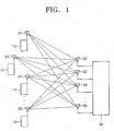
- the mobile station 10, 12, 14, ..., or 16 shown in FIG. 1 has only one antenna 20, 22, 24, ...., or 26, and b mobile stations (where b is a positive integer greater than 1) among the a mobile stations 10, 12, 14, ..., and 16 transmit a wireless signal to the base station 40 via a multiple or single carrier wave while using same resources such as time, frequency, or code.
- the base station 40 has c antennas 30, 32, 34, ..., and 36 (where c ⁇ a ) which receive the wireless signal.
- up-link data communication from the mobile station 10, 12, 14, ... or 16 to the base station 40 according to the present invention will be described below
- FIG. 2 is a block diagram illustrating a preferred embodiment (40A) of the apparatus 40 for up-link data communication shown in FIG. 1 according to the present invention.
- the apparatus 40A for up-link data communication includes an antenna terminal 60 comprised of c antennas 62, 64, 66, ..., and 68, a first multi-channel receiving unit 80, a first channel value estimating unit 82, and a first information estimating unit 84.
- FIG. 3 is a flow chart illustrating an embodiment of a method for up-link data communication according to the present invention implemented with the apparatus 40A for up-link data communication shown in FIG. 2.
- the method shown in FIG. 3 includes steps 90 and 92 of estimating channel values using a received signal that is extracted from a wireless signal, and step 94 of estimating user information.
- step 90 a wireless signal transmitted from the b mobile stations among the mobile stations 10, 12, 14, ..., and 16 is received, and a received signal is extracted from the received wireless signal.
- the c antennas 62, 64, 66, ..., and 68 included in the antenna terminal 60 receive a wireless signal
- the first multi-channel receiving unit 80 extracts a received signal from the wireless signal received via the c antennas 62, 64, 66, ..., and 68, and outputs the extracted received signal to the first channel value estimating unit 82 and the first information estimating unit 84, respectively.
- step 92 impulse responses are estimated using estimated received signals, and the estimated impulse responses are determined as estimated channel values.
- the first channel value estimating unit 82 estimates the impulse responses of channels that are formed between the a mobile stations 10, 12, 14, ..., and 16 and the antennas 62, 64, 66, ..., and 68, from the received signals and outputs the estimated impulse responses as the estimated channel values to the first information estimating unit 84.
- step 94 interference between the mobile stations 10, 12, 14, ..., and 16, that is, interference between symbols, is cancelled using the received signal and the channel values, and user information is estimated using the result of cancellation.
- Techniques such as zero forcing, minimum mean square error (MMSE), or interference cancellation, may be used to remove this interference.
- MMSE minimum mean square error
- interference is cancelled by multiplying a reverse of an estimated channel value by a received signal, but noise is increased.
- the MMSE and interference cancellation technique used to solve this problem are respectively disclosed in the articles "Layered Space Time Architecture for Wireless Communication in a Fading Environment when Using Multi Element Antennas" by G.J.
- the first information estimating unit 84 cancels interference between the mobile stations 10, 12, 14, ..., and 16 from a b signal received from the first multi-channel receiving unit 80 and the channel values received from the first channel value estimating unit 82, estimates user information from the result of cancellation, and outputs the estimated user information to an output terminal OUT1, i.e., a network.
- FIG. 4 is a flow chart illustrating another embodiment of the method for up-link data communication according to the present invention.
- the method shown in FIG. 4 includes steps 100 and 102 of estimating channel values using a received signal that is extracted from a wireless signal, and steps 104 through 108 of estimating user information depending on whether a communication time belongs to a random access period (RAP).
- RAP random access period
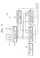
- FIG. 5 is a block diagram illustrating another preferred embodiment (40B) of the apparatus 40 for up-link data communication shown in FIG. 1 according to the present invention, which implements the method for up-link data communication shown in FIG. 4.
- the apparatus 40B for up-link data communication includes an antenna terminal 110 comprised of c antennas 112, 114, 116, ..., and 118, a second multi-channel receiving unit 120, a second channel value estimating unit 122, second and third information estimating units 124 and 126, and a first enabling unit 128.
- step 100 a wireless signal transmitted from a mobile station is received, and a received signal is extracted from the received wireless signal.
- the c antennas 112, 114, 116, ..., and 118 included in the antenna terminal 110 receive a wireless signal
- the second multi-channel receiving unit 120 extracts a b received signal from the wireless signal that is received via the c antennas 112, 114, 116, ..., and 118.
- step 102 impulse responses of channels that are formed between the mobile stations 10, 12, 14, ..., and 16 and the antennas 112, 114, 116, ..., and 118, are estimated using received signals, and the estimated impulse responses are determined as estimated channel values.
- the second channel value estimating unit 122 estimates the impulse responses of the channels that are formed between the mobile stations 10, 12, 14, ..., and 16 and the antennas 112, 114, 116, ..., and 118 from the signals received from the second multi-channel receiving unit 120, and outputs the estimated impulse responses as the estimated channel values to the second and third information estimating units 124 and 126, respectively.
- step 104 it is determined whether a communication time belongs to a random access period.
- the random access period means a period during which a mobile station transmits control information to a base station at an arbitrary time, for allocation of the resources.
- the first enabling unit 128 outputs first and second control signals C1 and C2 generated at the interval of a predetermined amount of time to the second and third information estimating units 124 and 126, respectively, and selectively operates the second and third information estimating units 124 and 126 one by one.
- the second information estimating unit 124 is enabled in response to the first control signal C1 generated by the first enabling unit 128, and when the communication time does not belong to the random access period, the third information estimating unit 126 is enabled in response to the second control signal C2 generated by the first enabling unit 128.
- step 106 If it is determined that the communication time belongs to the random access period, in step 106, interference between the mobile stations 10, 12, 14, ..., and 16 is cancelled using the received signal and the channel values, and user information is estimated using the result of cancellation.
- the second information estimating unit 124 cancels interference between the mobile stations 10, 12, 14, ..., and 16 from the signal received from the second multi-channel receiving unit 120 and the channel values received from the second channel value estimating unit 122, estimates user information from the result of cancellation, and outputs the estimated user information to an output terminal OUT2, i.e., a network.
- step 108 the received signal is combined using the channel values, and user information is estimated using the result of combination.
- the third information estimating unit 126 combines the signal received from the second multi-channel receiving unit 120 using the estimated channel values received from the second channel value estimating unit 122, estimates user information from the result of combination, and outputs the estimated user information to an output terminal OUT3, i.e., a network.
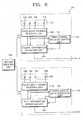
- FIG. 6 is a block diagram illustrating another preferred embodiment (40C) of the apparatus 40 for up-link data communication shown in FIG. 1 according to the present invention, which implements the method for up-link data communication shown in FIG. 4.
- the apparatus 40C for up-link data communication includes first and second up-link data communication units 140 and 142, and a second enabling unit 144.
- the first up-link data communication unit 140 shown in FIG. 6 is enabled in response to a third control signal C3 received from the second enabling unit 144, estimates channel values from a received signal extracted from a received wireless signal, cancels interference between the mobile stations 10, 12, 14, ..., and 16 from the estimated channel values and received signals, and estimates user information from the result of cancellation.
- the first up-link data communication unit 140 may be implemented with an antenna terminal 150 having c antennas 152, 154, 156, ..., and 158, a third multi-channel receiving unit 160, a third channel value estimating unit 162, and a fourth information estimating unit 164.
- step 100 the c antennas 152, 154, 156, ..., and 158 included in the antenna terminal 150 receive a wireless signal, and the third multi-channel receiving unit 160 extracts a received signal from the wireless signal received by the c antennas 152, 154, 156, ..., and 158 and outputs the extracted b received signal to the third channel value estimating unit 162 and the fourth information estimating units 164, respectively.
- the third channel value estimating unit 162 estimates channel values corresponding to impulse responses of channels that are formed between the mobile stations 10, 12, 14, ..., and 16 and the antennas 152, 154, 156, ..., and 158, from b signals received from the third multi-channel receiving unit 160 and outputs the estimated channel values to the fourth information estimating unit 164.
- the fourth information estimating unit 164 cancels interference between the mobile stations 10, 12, 14, ..., and 16 from a signal received from the third multi-channel receiving unit 160 and estimated channel values received from the third channel value estimating unit 162, estimates user information from the result of cancellation, and outputs the estimated user information to an output terminal OUT4, i.e., a network.
- the fourth information estimating unit 164 performs the same operation as that of the second information estimating unit 124 shown in FIG. 5.
- At least one of the third multi-channel receiving unit 160, the third channel value estimating unit 162, and the fourth information estimating unit 164 is enabled in response to the third control signal C3 output from the second enabling unit 144 so that the first up-link data communication unit 140 performs steps 100, 102, and 106 only when it is recognized that the communication time belongs to the random access period.
- the second up-link data communication unit 142 of FIG. 6 is enabled in response to the fourth control signal C4 received from the second enabling unit 144, estimates channel values from a received signal that is extracted from a received wireless signal, estimates user information from the result of combination of received signals using the estimated channel values, and outputs the estimated user information to an output terminal OUTS, i.e., a network.
- the second up-link data communication unit 142 may be implemented with an antenna terminal 180 having c antennas 182, 184, 186, ..., and 188, a fourth multi-channel receiving unit 190, a fourth channel value estimating unit 192, and a fifth information estimating unit 194.
- step 100 the c antennas 182, 184, 186, ..., and 188 included in the antenna terminal 180 receive a wireless signal, and the fourth multi-channel receiving unit 190 extracts a b received signal from the wireless signal received by the c antennas 182, 184, 186, ..., and 188 and outputs the extracted received signal to the fourth channel value estimating unit 192 and the fifth information estimating units 194, respectively.
- the fourth channel value estimating unit 192 estimates channel values corresponding to impulse responses of channels that are formed between the mobile stations 10, 12, 14, ..., and 16 and the antennas 182, 184, 186, ..., and 188, from signals received from the fourth multi-channel receiving unit 190 and outputs the estimated channel values to the fifth information estimating unit 194.
- the fifth information estimating unit 194 combines signals received from the fourth multi-channel receiving unit 190 using the estimated channel values received from the fourth channel value estimating unit 192, estimates user information from the result of combination, and outputs the estimated user information to an output terminal OUTS, i.e., a network.
- the fifth information estimating unit 194 performs the same operation as that of the third information estimating unit 126 shown in FIG. 5.
- At least one of the fourth multi-channel receiving unit 190, the fourth channel value estimating unit 192, and the fifth information estimating unit 194 is enabled in response to the fourth control signal C4 output from the second enabling unit 144 so that the second up-link data communication unit 142 performs steps 100, 102, and 108 only when it is recognized that the communication time does not belong to the random access period.
- the second enabling unit 144 outputs the third and fourth control signals C3 and C4 generated at the interval of a predetermined amount of time, to the first and second up-link data communication units 140 and 142, respectively, and selectively operates the first and second up-link data communication units 140 and 142 one by one.
- FIG. 7 illustrates the concept of random access in a conventional slotted ALOHA manner.
- Each rectangle represents a time slot as a communicable time, and boundaries between rectangles represent the instant at which communication can be begun.
- a mobile station (MS) 220 random-accesses a base station as shown by the arrow at an instant 1 at which one user, i.e., the MS 220, can begin communication at a random access period 210, the MS 220 can successfully access the base station.
- the MSs 222 and 224 simultaneously random-access the base station as shown by the arrows at an instant 2 at which the two or more MSs 222 and 224 can begin communication, the MSs 222 and 224 cannot successfully access the base station because of collision.
- FIG. 8 illustrates the concept of random access in a slotted ALOHA manner according to the present invention.
- Each of the rectangles represents a time slot as a communicable time, and boundaries between rectangles represent the instant at which communication can be begun.
- one mobile station (MS) 240 random-accesses a base station as shown by the arrow at the instant 1 at which one MS 240 can begin communication at a random access period 230, the MS 240 can successfully access the base station.
- two or more mobile stations (MSs) 242 and 244 simultaneously random-access a base station as shown by the arrows at the instant 2 at which the two or more mobile stations (MSs) 242 and 244 can begin communication, when c antennas of the base station is greater than 2, collision does not occur, and thus the MSs 242 and 244 can successfully access the base station.
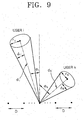
- FIG. 9 is a conceptual diagram for modeling a channel H.
- D represents an interval between antennas of a base station
- d i represents a distance between an i-th (1 ⁇ i ⁇ a ) mobile station and the base station
- ⁇ i represents a maximum angle in which an unequal radio wave deviates from a line connecting the mobile station to the base station
- ⁇ i represents an angle formed by a line perpendicular to a line connecting antennas of the base station to one another and the line connecting the mobile station to the base station.
- a channel through which a wireless signal received from the i-th mobile station to a j-th antenna of the base station passes is h ij
- a channel H i through which the wireless signal is transmitted from the i-th mobile station to the base station is represented as a row vector like in Equation 1.
- H i [ h i 1 ... h T ib ]
- the channel H through which a wireless signal is transmitted from a mobile stations 10, 12, 14, ..., and 16 to the base station 40 may be expressed as a matrix like in Equation 2.
- H [H 1 ... H a ] T
- h ij is modeled like in Equation 3.
- h ij ⁇ i a ij e - j 2 ⁇ ( k - j ) D ⁇ sin ⁇ i
- a ij represents a complex Gaussian process
- ⁇ re represents a carrier frequency
- ⁇ i represents a path loss and may be modeled like in Equation 4.
- ⁇ i 20log( 4 ⁇ f c ) + ⁇ 10log d i + X ⁇ ( dB )
- f represents a carrier frequency
- c represents the speed of light
- ⁇ represents a path loss exponent
- X ⁇ represents a fading value in a wider range having normalized log distribution. Meanings of variables f, c, ⁇ , and X ⁇ are disclosed in the book "Smart Antennas for Wireless Communications” by Theodore Rappaport, pp. 36-37.
- FIG. 10 is a graph for comparing the performance of the present invention with that of prior art.
- the horizontal axis represents the number a of mobile stations
- the vertical axis represents throughput
- the full lines represent throughputs obtained by the method and apparatus for up-link data communication according to the present invention
- the dotted lines represent throughputs obtained by the conventional method and apparatus for up-link data communication using MRC.
- the antenna interval D is varied to 0.1 ⁇ , 0.5 ⁇ , ⁇ , 2 ⁇ , and 10 ⁇ , the pass loss exponent ⁇ is set to 3, normalized log fading X ⁇ is set to 0, frequency f is set to 5 GHz, radius r i is set to 0.1 time of d i , the position of the mobile station is uniformly distributed in a circle having a predetermined range, and in case of no fading, the predetermined range is set to a distance in which binary phase shift keying (BPSK) having a bit error rate (BER) of 10 -7 can be successfully reached.
- BPSK binary phase shift keying
- BER bit error rate
- the correlation is reduced such that throughput, the capacity of the channel, is increased about to the number of antennas compared to the conventional method.
- the random access period can be reduced such that a time required for transmitting and receiving another data is relatively increased and the capacity of the channel as the entire throughput, is increased to the number of antennas of a base station even if the number of antennas of each of mobile stations is one.
Landscapes
- Engineering & Computer Science (AREA)
- Computer Networks & Wireless Communication (AREA)
- Signal Processing (AREA)
- Power Engineering (AREA)
- Mobile Radio Communication Systems (AREA)
- Radio Transmission System (AREA)
Applications Claiming Priority (2)
| Application Number | Priority Date | Filing Date | Title |
|---|---|---|---|
| KR1020020017605A KR20030078521A (ko) | 2002-03-30 | 2002-03-30 | 상향 데이타 통신 장치 및 방법 |
| KR2002017605 | 2002-03-30 |
Publications (2)
| Publication Number | Publication Date |
|---|---|
| EP1365522A2 true EP1365522A2 (de) | 2003-11-26 |
| EP1365522A3 EP1365522A3 (de) | 2005-07-13 |
Family
ID=29267876
Family Applications (1)
| Application Number | Title | Priority Date | Filing Date |
|---|---|---|---|
| EP03250930A Withdrawn EP1365522A3 (de) | 2002-03-30 | 2003-02-14 | Vorrichtung und Verfahren zur Aufwärtskommunikation der Daten |
Country Status (5)
| Country | Link |
|---|---|
| US (1) | US20040203445A1 (de) |
| EP (1) | EP1365522A3 (de) |
| JP (1) | JP3860796B2 (de) |
| KR (1) | KR20030078521A (de) |
| CN (1) | CN1218601C (de) |
Families Citing this family (8)
| Publication number | Priority date | Publication date | Assignee | Title |
|---|---|---|---|---|
| US20070030914A1 (en) * | 2005-08-02 | 2007-02-08 | Samsung Electronics Co., Ltd. | Method and system for channel estimation and interference cancellation in an orthogonal frequency division multiple access network |
| KR100896442B1 (ko) * | 2005-12-23 | 2009-05-14 | 삼성전자주식회사 | 광대역 무선 통신시스템에서 인접 셀의 간섭을 제거하기위한 장치 및 방법 |
| KR100681393B1 (ko) * | 2006-03-31 | 2007-02-28 | 재단법인서울대학교산학협력재단 | 가상 센서를 이용한 다중경로 검출방법 |
| CN101485121B (zh) * | 2006-07-12 | 2012-03-21 | 艾利森电话股份有限公司 | 干扰减小的方法和设备 |
| CN101646251B (zh) * | 2008-08-07 | 2012-07-18 | 中兴通讯股份有限公司 | 随机接入过程和测量间隙冲突的处理方法 |
| JP5518649B2 (ja) * | 2010-09-13 | 2014-06-11 | 株式会社Nttドコモ | 無線通信制御方法、無線通信システム、無線基地局および移動端末 |
| KR20130104289A (ko) * | 2012-03-13 | 2013-09-25 | 삼성전자주식회사 | 오프셋 값을 추정하는 장치, 방법, 수신장치 및 수신장치에서 신호를 처리하는 방법 |
| US20230397105A1 (en) * | 2020-10-26 | 2023-12-07 | Commscope Technologies Llc | Reducing radio unit power consumption |
Family Cites Families (15)
| Publication number | Priority date | Publication date | Assignee | Title |
|---|---|---|---|---|
| US5828658A (en) * | 1991-12-12 | 1998-10-27 | Arraycomm, Inc. | Spectrally efficient high capacity wireless communication systems with spatio-temporal processing |
| JP3204111B2 (ja) * | 1996-08-28 | 2001-09-04 | 松下電器産業株式会社 | 指向性制御アンテナ装置 |
| JP3391662B2 (ja) * | 1997-06-06 | 2003-03-31 | 松下電器産業株式会社 | アダプティブアレーアンテナ受信装置 |
| US6314147B1 (en) * | 1997-11-04 | 2001-11-06 | The Board Of Trustees Of The Leland Stanford Junior University | Two-stage CCI/ISI reduction with space-time processing in TDMA cellular networks |
| KR100459010B1 (ko) * | 1998-06-17 | 2005-04-06 | 주홍정보통신주식회사 | 다중경로환경에서안테나배열을이용한간섭제거시스템 |
| US6385185B1 (en) * | 1998-06-25 | 2002-05-07 | Lucent Technologies Inc. | Methods and apparatus for coherent detection of signals with orthogonal data modulation |
| EP1054519A1 (de) * | 1999-05-11 | 2000-11-22 | Alcatel | Diversityübertragung in einem Mobilfunksystem |
| US6151487A (en) * | 1999-08-31 | 2000-11-21 | Hughes Electronics Corporation | Demodulation structure for fast fading cellular channels |
| DE19943687C1 (de) * | 1999-09-06 | 2001-07-26 | Hertz Inst Heinrich | Verfahren und Anordnung zur Strahlformung eines Rake-Empfängers für den Ein-Nutzer-Empfang für den Uplink-Kanal in Mobilfunksystemen |
| US6922445B1 (en) * | 1999-12-15 | 2005-07-26 | Intel Corporation | Method and system for mode adaptation in wireless communication |
| KR20010058972A (ko) * | 1999-12-30 | 2001-07-06 | 박종섭 | 스마트 안테나를 이용한 무선가입자망 시스템 |
| US6232921B1 (en) * | 2000-01-11 | 2001-05-15 | Lucent Technologies Inc. | Method and system for adaptive signal processing for an antenna array |
| US6778612B1 (en) * | 2000-08-18 | 2004-08-17 | Lucent Technologies Inc. | Space-time processing for wireless systems with multiple transmit and receive antennas |
| US20020164968A1 (en) * | 2001-03-06 | 2002-11-07 | Magis Networks, Inc. | Probing scheme for diversity antenna branch selection |
| US7047016B2 (en) * | 2001-05-16 | 2006-05-16 | Qualcomm, Incorporated | Method and apparatus for allocating uplink resources in a multiple-input multiple-output (MIMO) communication system |
-
2002
- 2002-03-30 KR KR1020020017605A patent/KR20030078521A/ko not_active Ceased
-
2003
- 2003-02-14 EP EP03250930A patent/EP1365522A3/de not_active Withdrawn
- 2003-02-14 CN CN031378803A patent/CN1218601C/zh not_active Expired - Fee Related
- 2003-02-14 JP JP2003036296A patent/JP3860796B2/ja not_active Expired - Fee Related
- 2003-03-10 US US10/383,658 patent/US20040203445A1/en not_active Abandoned
Also Published As
| Publication number | Publication date |
|---|---|
| JP3860796B2 (ja) | 2006-12-20 |
| CN1455614A (zh) | 2003-11-12 |
| KR20030078521A (ko) | 2003-10-08 |
| US20040203445A1 (en) | 2004-10-14 |
| CN1218601C (zh) | 2005-09-07 |
| JP2003304192A (ja) | 2003-10-24 |
| EP1365522A3 (de) | 2005-07-13 |
Similar Documents
| Publication | Publication Date | Title |
|---|---|---|
| EP0926916B1 (de) | Schnurloses Kommunikationssystem mit Vielfachzugriff durch Raummultiplexierung | |
| EP1915827B1 (de) | Koordination von mehrbenutzerübertragung in der abwärtsstrecke eines drahtlosen kommunikationssystems mit mehreren antennen | |
| AU2004223381B2 (en) | Co-channel wireless communication methods and systems using nonsymmetrical alphabets | |
| AU2001296598B2 (en) | Method and apparatus for estimating downlink beamforming weights in a communications system | |
| EP2171875B1 (de) | Antennengewichtsberechnung auf der basis der störungszurückweisungsfähigkeiten von benutzern | |
| US20050031062A1 (en) | Method and apparatus for determining a shuffling pattern based on a minimum signal to noise ratio in a double space-time transmit diversity system | |
| EP0926913A2 (de) | Zellulares Funkkommunikationssystem mit Teilnehmeraufteilung mittels Antenne-Strahlformung | |
| US7778309B2 (en) | Apparatus and method for canceling interference from neighbor cells in broadband communication system | |
| EP2118962A1 (de) | Wellenförmige übertragungsmuster für mehrere simultansender zur unterstützung der signaltrennung an einem empfänger | |
| EP1365522A2 (de) | Vorrichtung und Verfahren zur Aufwärtskommunikation der Daten | |
| US6734822B2 (en) | Transmission system and method on a forward link | |
| US11026105B1 (en) | Fingerprint-based beam interference cancellation system and method thereof | |
| Farsakh et al. | Maximizing the SDMA Mobile Radio Capacity Increase by DOA Sensitive Channel Allocation | |
| Matsumoto et al. | Beam-selection performance analysis of a switched multibeam antenna system in mobile communications environments | |
| US6021334A (en) | Method for transmission by a base station equipped with a multi-element antenna to a mobile | |
| US20070189148A1 (en) | Signal transmitting method (variants) and device for carrying out said method | |
| Khosroazad et al. | Using physical layer network coding to improve NOMA system throughput with energy harvesting users | |
| Zhang et al. | Multi-channel smart antennas in wireless networks | |
| Bengtsson | Robust and constrained downlink beamforming | |
| US6801791B2 (en) | Cellular communications system and related methods | |
| Murakami et al. | Performance evaluation of uplink multiuser MIMO-OFDM system with single RF chain receiver | |
| Kim et al. | Performance analysis of an MC-CDMA system with antenna array in a fading channel | |
| Ghaedi et al. | Side Lobe Canceller Structure-Based Spatial Interference Cancellation and performance enhancement of the MIMO wireless systems | |
| Matsumuro et al. | Proactive rank adaptation method using probabilistic interference arrival information | |
| Kishiyama et al. | Weight estimation for downlink null steering in a TDD/SDMA system |
Legal Events
| Date | Code | Title | Description |
|---|---|---|---|
| PUAI | Public reference made under article 153(3) epc to a published international application that has entered the european phase |
Free format text: ORIGINAL CODE: 0009012 |
|
| 17P | Request for examination filed |
Effective date: 20030312 |
|
| AK | Designated contracting states |
Kind code of ref document: A2 Designated state(s): AT BE BG CH CY CZ DE DK EE ES FI FR GB GR HU IE IT LI LU MC NL PT SE SI SK TR |
|
| AX | Request for extension of the european patent |
Extension state: AL LT LV MK RO |
|
| PUAL | Search report despatched |
Free format text: ORIGINAL CODE: 0009013 |
|
| AK | Designated contracting states |
Kind code of ref document: A3 Designated state(s): AT BE BG CH CY CZ DE DK EE ES FI FR GB GR HU IE IT LI LU MC NL PT SE SI SK TR |
|
| AX | Request for extension of the european patent |
Extension state: AL LT LV MK RO |
|
| RIC1 | Information provided on ipc code assigned before grant |
Ipc: 7H 04B 7/08 B Ipc: 7H 04L 25/02 A |
|
| AKX | Designation fees paid |
Designated state(s): DE FI FR GB SE |
|
| 17Q | First examination report despatched |
Effective date: 20080609 |
|
| STAA | Information on the status of an ep patent application or granted ep patent |
Free format text: STATUS: THE APPLICATION IS DEEMED TO BE WITHDRAWN |
|
| 18D | Application deemed to be withdrawn |
Effective date: 20081021 |