EP1365469A2 - Improved heat transfer due to superficial concavities in fluid passages of solid oxide fuel cells - Google Patents
Improved heat transfer due to superficial concavities in fluid passages of solid oxide fuel cells Download PDFInfo
- Publication number
- EP1365469A2 EP1365469A2 EP03252624A EP03252624A EP1365469A2 EP 1365469 A2 EP1365469 A2 EP 1365469A2 EP 03252624 A EP03252624 A EP 03252624A EP 03252624 A EP03252624 A EP 03252624A EP 1365469 A2 EP1365469 A2 EP 1365469A2
- Authority
- EP
- European Patent Office
- Prior art keywords
- concavities
- disposed
- solid oxide
- oxide fuel
- fuel cell
- Prior art date
- Legal status (The legal status is an assumption and is not a legal conclusion. Google has not performed a legal analysis and makes no representation as to the accuracy of the status listed.)
- Withdrawn
Links
Images


Classifications
-
- H—ELECTRICITY
- H01—ELECTRIC ELEMENTS
- H01M—PROCESSES OR MEANS, e.g. BATTERIES, FOR THE DIRECT CONVERSION OF CHEMICAL ENERGY INTO ELECTRICAL ENERGY
- H01M8/00—Fuel cells; Manufacture thereof
- H01M8/10—Fuel cells with solid electrolytes
- H01M8/12—Fuel cells with solid electrolytes operating at high temperature, e.g. with stabilised ZrO2 electrolyte
-
- H—ELECTRICITY
- H01—ELECTRIC ELEMENTS
- H01M—PROCESSES OR MEANS, e.g. BATTERIES, FOR THE DIRECT CONVERSION OF CHEMICAL ENERGY INTO ELECTRICAL ENERGY
- H01M8/00—Fuel cells; Manufacture thereof
- H01M8/02—Details
- H01M8/0202—Collectors; Separators, e.g. bipolar separators; Interconnectors
- H01M8/0258—Collectors; Separators, e.g. bipolar separators; Interconnectors characterised by the configuration of channels, e.g. by the flow field of the reactant or coolant
-
- H—ELECTRICITY
- H01—ELECTRIC ELEMENTS
- H01M—PROCESSES OR MEANS, e.g. BATTERIES, FOR THE DIRECT CONVERSION OF CHEMICAL ENERGY INTO ELECTRICAL ENERGY
- H01M8/00—Fuel cells; Manufacture thereof
- H01M8/02—Details
-
- H—ELECTRICITY
- H01—ELECTRIC ELEMENTS
- H01M—PROCESSES OR MEANS, e.g. BATTERIES, FOR THE DIRECT CONVERSION OF CHEMICAL ENERGY INTO ELECTRICAL ENERGY
- H01M8/00—Fuel cells; Manufacture thereof
- H01M8/02—Details
- H01M8/0202—Collectors; Separators, e.g. bipolar separators; Interconnectors
- H01M8/0258—Collectors; Separators, e.g. bipolar separators; Interconnectors characterised by the configuration of channels, e.g. by the flow field of the reactant or coolant
- H01M8/026—Collectors; Separators, e.g. bipolar separators; Interconnectors characterised by the configuration of channels, e.g. by the flow field of the reactant or coolant characterised by grooves, e.g. their pitch or depth
-
- H—ELECTRICITY
- H01—ELECTRIC ELEMENTS
- H01M—PROCESSES OR MEANS, e.g. BATTERIES, FOR THE DIRECT CONVERSION OF CHEMICAL ENERGY INTO ELECTRICAL ENERGY
- H01M8/00—Fuel cells; Manufacture thereof
- H01M8/02—Details
- H01M8/0202—Collectors; Separators, e.g. bipolar separators; Interconnectors
- H01M8/0267—Collectors; Separators, e.g. bipolar separators; Interconnectors having heating or cooling means, e.g. heaters or coolant flow channels
-
- H—ELECTRICITY
- H01—ELECTRIC ELEMENTS
- H01M—PROCESSES OR MEANS, e.g. BATTERIES, FOR THE DIRECT CONVERSION OF CHEMICAL ENERGY INTO ELECTRICAL ENERGY
- H01M8/00—Fuel cells; Manufacture thereof
- H01M8/04—Auxiliary arrangements, e.g. for control of pressure or for circulation of fluids
- H01M8/04007—Auxiliary arrangements, e.g. for control of pressure or for circulation of fluids related to heat exchange
-
- H—ELECTRICITY
- H01—ELECTRIC ELEMENTS
- H01M—PROCESSES OR MEANS, e.g. BATTERIES, FOR THE DIRECT CONVERSION OF CHEMICAL ENERGY INTO ELECTRICAL ENERGY
- H01M8/00—Fuel cells; Manufacture thereof
- H01M8/10—Fuel cells with solid electrolytes
- H01M8/12—Fuel cells with solid electrolytes operating at high temperature, e.g. with stabilised ZrO2 electrolyte
- H01M2008/1293—Fuel cells with solid oxide electrolytes
-
- H—ELECTRICITY
- H01—ELECTRIC ELEMENTS
- H01M—PROCESSES OR MEANS, e.g. BATTERIES, FOR THE DIRECT CONVERSION OF CHEMICAL ENERGY INTO ELECTRICAL ENERGY
- H01M8/00—Fuel cells; Manufacture thereof
- H01M8/02—Details
- H01M8/0202—Collectors; Separators, e.g. bipolar separators; Interconnectors
- H01M8/0247—Collectors; Separators, e.g. bipolar separators; Interconnectors characterised by the form
- H01M8/0254—Collectors; Separators, e.g. bipolar separators; Interconnectors characterised by the form corrugated or undulated
-
- Y—GENERAL TAGGING OF NEW TECHNOLOGICAL DEVELOPMENTS; GENERAL TAGGING OF CROSS-SECTIONAL TECHNOLOGIES SPANNING OVER SEVERAL SECTIONS OF THE IPC; TECHNICAL SUBJECTS COVERED BY FORMER USPC CROSS-REFERENCE ART COLLECTIONS [XRACs] AND DIGESTS
- Y02—TECHNOLOGIES OR APPLICATIONS FOR MITIGATION OR ADAPTATION AGAINST CLIMATE CHANGE
- Y02E—REDUCTION OF GREENHOUSE GAS [GHG] EMISSIONS, RELATED TO ENERGY GENERATION, TRANSMISSION OR DISTRIBUTION
- Y02E60/00—Enabling technologies; Technologies with a potential or indirect contribution to GHG emissions mitigation
- Y02E60/30—Hydrogen technology
- Y02E60/50—Fuel cells
Definitions
- the present invention relates generally to power generation equipment, and more particularly to improved fluid passages for solid oxide fuel cells.
- a high temperature, solid oxide fuel cell (hereinafter "sofc”) stack is typically constructed of an array of axially-elongated tubular-shaped connected sofcs and associated fuel and air distribution equipment.
- tubular sofc are planar cross flow fuel cells, counterflow fuel cells and parallel flow fuel cells which are constructed from flat single cell members.
- Such members typically comprise trilayer anode/electrolyte/cathode components which conduct current from cell to cell and provide channels for gas flow into a cubic structure or stack.
- Sofcs generate electrical energy through electrochemical reactions between an oxidant and hydrocarbon fuel gas to produce a flow of electrons in an external circuit.
- sofcs generate waste heat that is typically removed via an oxidant in order to maintain a desired temperature level of sofc components such as the anode, cathode and electrolyte.
- Sofcs typically comprise cooling channels (in alternating flat single cell sections) or riser tubes (in tubular sofcs) in which the oxidant, typically air, is used to aid in the transfer or removal of the waste heat so as to maintain the stack temperature at or below prescribed limits and maintain a predetermined thermal gradient in the sofc.
- Such channels or riser tubes typically comprise smooth surfaces having the undesired characteristic of providing low thermal transfer coefficients between the channel or tube surface and the oxidant.
- One embodiment of the present invention comprises a solid oxide fuel cell comprising a thermal management section and an electrolytic section disposed adjacent the thermal management section wherein a plurality of concavities are disposed on at least one of the thermal management and electrolytic sections so as to cause hydrodynamic interactions and affect the heat transfer rate between a fluid and the concavities when the fluid is disposed over the concavities.
- Typical solid oxide fuel cells are disposed in a power generation apparatus and comprise tubular solid oxide fuel cells (hereinafter SOFCs) (see Figures 1-2) or planar cross flow solid oxide fuel cell stacks (see Figures 3-6).
- SOFCs typically comprise a thermal management section 101 and an electrolytic section 102 (see Figure 1).
- the thermal management section 101 typically comprises a riser tube 110 disposed within the electrolytic section 102 for tubular SOFCs.
- the thermal management section 101 typically comprises an (meaning at least one) oxidant section 150 and a (meaning at least one) fuel section 160 wherein the electrolytic section 102 is typically disposed between both sections for planar cross flow SOFCs (see Figures 3-6).
- the electrolytic section 102 typically comprises an anode 190, cathode 200 and an electrolyte 210.
- the terms “thereon”, “therein”, “over”, “above”, “under” and the like are used to refer to relative location of elements of the SOFC 100 as illustrated in the Figures and are not meant to be a limitation in any manner with respect to the orientation or operation of the SOFC 100.
- tubular solid oxide fuel cells see Figures 1-2
- planar cross flow solid oxide fuel cells see Figures 3-6
- a gaseous fuel (as indicated by the solid arrow termed “FUEL” in drawing Figures 1-2), such as natural gas or hydrogen, is directed axially over an external wall surface 135 of the SOFC 100.
- an oxidant (as indicated by the dashed arrows termed “OXIDANT” in drawing Figures 1-2), such as air or oxygen, is fed through the riser tube 110 (see Figure 1).
- the riser tube 110 comprises a riser tube internal surface 120 and a riser tube external surface 130 and is positioned within the annulus of the SOFC 100.
- Such oxidant is initially introduced into the riser tube internal surface 120 wherein the oxidant subsequently flows back up the SOFC 100 between the riser tube external surface 130 and an internal wall surface 135.
- the planar cross flow SOFC 100 comprises the oxidant section 150 having an (meaning at least one) oxidant channel 170 disposed therein and the fuel section 160 having a (meaning at least one) fuel channel 180 disposed therein (see Figure 3).
- This embodiment of the SOFC 100 is typically constructed from flat single cell sections that typically comprise the oxidant section 150 and the fuel section 160 wherein the channels of such sections allow the flow of an oxidant (as indicated by the dashed arrows termed "OXIDANT" in drawing Figures 3-6) and a gaseous fuel (as indicated by the solid arrow termed "FUEL" in drawing Figures 3-6) into a cubic structure or stack.
- OXIDANT an oxidant
- FUEL gaseous fuel
- the fuel is directed over the external wall surface 135 of the tubular SOFC 100 (see Figures 1-2) or through the fuel channel 180 of the planar cross flow SOFC 100 (see Figures 3-6).
- the oxidant typically preheated air or oxygen, is directed through the riser tube 110 in the tubular SOFC 100 (see Figures 1-2) or directed through the oxidant channel 170 of the planar cross flow SOFC 100 (see Figures 3-6).
- the oxidant oxygen molecules
- the cathode 200 passes through the cathode 200 and forms oxygen ions at a cathode electrolyte interface 191.
- the oxygen ions migrate through the electrolyte 210 to combine with the fuel at an anode electrolyte interface 192 thereby releasing electrons at the anode 190.
- the electrons are then collected at the cathode 200 through an external load circuit (not shown) thereby generating a flow of electrical current in the external load circuit from the anode 190 to the cathode 200.
- the SOFC 100 generates heat that must be removed in order to maintain a desired temperature level and a predetermined thermal gradient in the SOFC 100.
- Such removal of heat is typically accomplished through the introduction of the oxidant into the riser tube 110 (see Figures 1-2) or in the oxidant channel 170 (see Figure 3) so that the oxidant fluid flow removes heat energy from the SOFC 100.
- Figure 1 shows a plurality of concavities 140 disposed on the riser tube internal surface 120, riser tube external surface 130, internal wall surface 135 and external wall surface 136 of the SOFC 100.
- the term "concavity” refers to depressions, indentations, dimples, pits or the like.
- the shape of the concavities 140 is typically hemispherical or inverted and truncated conically shaped. In another embodiment, the shape of the concavities 140 is typically any sector of a full hemisphere. In some embodiments, the concavities 140 are disposed on an entirety or a portion of the abovementioned surfaces.
- the concavities 140 are formed on the abovementioned surfaces in a pattern that serves to enhance the heat transfer from the SOFC 100 components, such as the anode 190, cathode 200 and electrolyte 210, to a fluid, such as the oxidant or the gaseous fuel.
- a fluid such as the oxidant or the gaseous fuel.
- the concavities 140 are disposed on the SOFC external surface 136 (see Figure 1) or disposed within the fuel channel 180 (see Figures 3-6) so as to enhance the removal of heat from the SOFC 100 components to the gaseous fuel.
- the fluid is introduced into the SOFC 100 so as to be disposed over the concavities 140.
- hydrodynamic interactions refers to the interactions between the concavities 140 and the fluid in which each concavity creates a pressure field within the concavity so as to create a vortex pattern in a portion of the flow of the fluid (not shown).
- the portion of the flow of the fluid interacts with the mainstream flow of the fluid
- the portion of the flow of the fluid is directed to the surface of the channel so as to interact thermally with the surface thereby resulting in enhanced heat transfer from the SOFC 100 components to the fluid.
- the thermal interaction between the fluid and each respective concavity is increased due to an increase, with respect to a surface without concavities, in the surface area caused by the shape of each respective cavity.
- the fluid interacts with such increased surface area thereby enhancing the removal of heat energy from the SOFC 100.
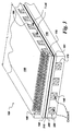
- the depth "Y” (see Figure 1) for a given one of the concavities 140 typically remains constant through the length "L" of the tubular SOFC 100 (see Figure 2) or through the length "L” of the planar cross flow SOFC 100 (see Figures 3-6).
- the depth "Y” (see Figure 1) is generally in the range between about 0.10 to about 0.50 times the concavity surface diameter "d".
- the depth (Y) of the concavities 140 is in the range between about 0.002 inches to about 0.125 inches.
- the center-to-center spacing "X" (see Figure 1) of the concavities 140 is generally in the range between about 1.1 to about 2 times the surface diameter "d" of the concavities 140.
- the concavities 140 are typically formed by using a pulse electrochemical machining (PECM) process.
- EDM electro-discharge machining
- the concavities 140 are disposed within the oxidant channel 170 and the fuel channel 180 (see Figure 3). In an alternative embodiment, the concavities 140 are disposed in either the oxidant channel 170 or the fuel channel 180.
- the SOFC 100 comprises the oxidant section 150 and the fuel section 160 having a first flow member 220 and a second flow member 230 disposed therein, respectively (see Figure 4). In this embodiment, the first flow member 220 and the second flow member 230 comprise a first wedge and a second wedge, respectively.
- the term "wedge" refers to the shape of the first flow member 220 and the second flow member 230 wherein the shape of such members tapers to an edge.
- the first and second wedges typically comprise a plurality of support members 240 that serve to align and support the wedges in the oxidant section 150 and the fuel section 160.
- Figure 6 shows the oxidant channel 170 and the fuel channel 180 formed into tapered channels.
- tapered channels refers to the shape of the channels in which such channels taper to an edge from the oxidant flow inlet 250 to the oxidant flow outlet (not shown) and a fuel flow inlet 260 to a fuel flow outlet 270.
- the wedges (see Figure 4) and the tapered channels (see Figure 6) enhance the flow rate of oxidant or fuel in the oxidant section 150 or the fuel section 160, respectively, thereby increasing the heat transfer in the SOFC 100.
- the wedge (see Figure 4) shape creates a converging flow area from the oxidant flow inlet 250 to the oxidant flow outlet (not shown) of oxidant section 150 thereby affecting the heat transfer rate between the SOFC 100 components and the oxidant.
- the tapered channels of Figure 6 exhibit the same characteristics as the wedges described above.
- the wedges (see Figure 4) or the tapered channels (see Figure 6) to create converging flow results in a substantially uniform rate of heat transfer throughout the flow path of the oxidant or gaseous fuel by effectively offsetting the decreasing thermal potential for convective heat transfer caused by the temperature increase of the oxidant or gaseous fuel thereby affecting the thermal gradient in the oxidant section 150 or the fuel section 160, respectively.
- the heat transfer rate is further increased by having the concavities 140 disposed on the wedges (see Figure 4) or the tapered channels (see Figure 6) wherein such increase is due to the hydrodynamic interactions caused by the oxidant or the gaseous fuel when disposed over the concavities 140.
- the concavities 140 are disposed on an entirety or a portion of the above mentioned tapered channels or wedges (see Figure 4).
- first flow member 220 and the second flow member 230 comprise a first corrugated member and a second corrugated member, respectively (see Figure 5).
- corrugated refers to the material shape of the first flow member 220 and the second flow member 230 such that the material is shaped to form a ridged or furrowed surface.
- the concavities 140 are disposed on the corrugated members so as to cause hydrodynamic interactions between the fluid (oxidant or gaseous fuel) and the concavities 140 thereby increasing the heat transfer rate between the components of the SOFC 100 and the fluid.
- the corrugated members are formed from sheet metal, for example, stainless steel sheet metal. It will be appreciated that the sheet metal typically varies in thickness depending upon the desired depth configuration of the concavities 140 and the peaks and valleys of the corrugated member serve the function of contacting the anode 190 and the cathode 200 for current flow.
Abstract
Description
- The present invention relates generally to power generation equipment, and more particularly to improved fluid passages for solid oxide fuel cells.
- A high temperature, solid oxide fuel cell (hereinafter "sofc") stack is typically constructed of an array of axially-elongated tubular-shaped connected sofcs and associated fuel and air distribution equipment. In addition, typical alternative constructions to the tubular sofc are planar cross flow fuel cells, counterflow fuel cells and parallel flow fuel cells which are constructed from flat single cell members. Such members typically comprise trilayer anode/electrolyte/cathode components which conduct current from cell to cell and provide channels for gas flow into a cubic structure or stack.
- Sofcs generate electrical energy through electrochemical reactions between an oxidant and hydrocarbon fuel gas to produce a flow of electrons in an external circuit. In addition, sofcs generate waste heat that is typically removed via an oxidant in order to maintain a desired temperature level of sofc components such as the anode, cathode and electrolyte.
- While sofcs have demonstrated the potential for high efficiency and low pollution in power generation, some problems remain associated with temperature regulation of the components in sofcs. Sofcs typically comprise cooling channels (in alternating flat single cell sections) or riser tubes (in tubular sofcs) in which the oxidant, typically air, is used to aid in the transfer or removal of the waste heat so as to maintain the stack temperature at or below prescribed limits and maintain a predetermined thermal gradient in the sofc. Such channels or riser tubes; however, typically comprise smooth surfaces having the undesired characteristic of providing low thermal transfer coefficients between the channel or tube surface and the oxidant.
- Accordingly, there is a need in the art for a sofc having improved fluid passages that provide improved heat transfer characteristics.
- One embodiment of the present invention comprises a solid oxide fuel cell comprising a thermal management section and an electrolytic section disposed adjacent the thermal management section wherein a plurality of concavities are disposed on at least one of the thermal management and electrolytic sections so as to cause hydrodynamic interactions and affect the heat transfer rate between a fluid and the concavities when the fluid is disposed over the concavities.
- The invention will now be described in greater detail, by way of example, with reference to the drawings, in which:-
- FIGURE 1 is a cross sectional view of a tubular solid oxide fuel cell in accordance with one embodiment of the present invention;
- FIGURE 2 is a top perspective view of Figure 1 taken along lines 1-1;
- FIGURE 3 is a perspective view of a planar cross flow solid oxide fuel cell in accordance with another embodiment of the present invention;
- FIGURE 4 is a perspective view of the planar cross flow solid oxide fuel cell of FIGURE 3 in accordance with another embodiment of the present invention;
- FIGURE 5 is a perspective view of the planar cross flow solid oxide fuel cell of FIGURE 3 in accordance with another embodiment of the present invention; and
- FIGURE 6 is a perspective view of the planar cross flow solid oxide fuel cell of FIGURE 3 in accordance with another embodiment of the present invention.
-
- Typical solid oxide fuel cells are disposed in a power generation apparatus and comprise tubular solid oxide fuel cells (hereinafter SOFCs) (see Figures 1-2) or planar cross flow solid oxide fuel cell stacks (see Figures 3-6). In addition, SOFCs typically comprise a thermal management section 101 and an electrolytic section 102 (see Figure 1). As discussed below, the thermal management section 101 typically comprises a
riser tube 110 disposed within the electrolytic section 102 for tubular SOFCs. In addition, the thermal management section 101 typically comprises an (meaning at least one)oxidant section 150 and a (meaning at least one)fuel section 160 wherein the electrolytic section 102 is typically disposed between both sections for planar cross flow SOFCs (see Figures 3-6). The electrolytic section 102 typically comprises ananode 190,cathode 200 and anelectrolyte 210. As used herein, the terms "thereon", "therein", "over", "above", "under" and the like are used to refer to relative location of elements of the SOFC 100 as illustrated in the Figures and are not meant to be a limitation in any manner with respect to the orientation or operation of the SOFC 100. For purposes of simplicity, both tubular solid oxide fuel cells (see Figures 1-2) and planar cross flow solid oxide fuel cells (see Figures 3-6) will hereinafter be generically described asSOFCs 100. - In operation, a gaseous fuel (as indicated by the solid arrow termed "FUEL" in drawing Figures 1-2), such as natural gas or hydrogen, is directed axially over an
external wall surface 135 of the SOFC 100. In addition, an oxidant (as indicated by the dashed arrows termed "OXIDANT" in drawing Figures 1-2), such as air or oxygen, is fed through the riser tube 110 (see Figure 1). Theriser tube 110 comprises a riser tubeinternal surface 120 and a riser tubeexternal surface 130 and is positioned within the annulus of the SOFC 100. Such oxidant is initially introduced into the riser tubeinternal surface 120 wherein the oxidant subsequently flows back up theSOFC 100 between the riser tubeexternal surface 130 and aninternal wall surface 135. - The planar cross flow SOFC 100 comprises the
oxidant section 150 having an (meaning at least one)oxidant channel 170 disposed therein and thefuel section 160 having a (meaning at least one)fuel channel 180 disposed therein (see Figure 3). This embodiment of theSOFC 100 is typically constructed from flat single cell sections that typically comprise theoxidant section 150 and thefuel section 160 wherein the channels of such sections allow the flow of an oxidant (as indicated by the dashed arrows termed "OXIDANT" in drawing Figures 3-6) and a gaseous fuel (as indicated by the solid arrow termed "FUEL" in drawing Figures 3-6) into a cubic structure or stack. It will be appreciated that the position and orientation of theoxidant section 150 and thefuel section 160 can vary and the position and orientation of such sections in Figures 3-6 are used by way of illustration and not limitation. - In operation, the fuel is directed over the
external wall surface 135 of the tubular SOFC 100 (see Figures 1-2) or through thefuel channel 180 of the planar cross flow SOFC 100 (see Figures 3-6). The oxidant, typically preheated air or oxygen, is directed through theriser tube 110 in the tubular SOFC 100 (see Figures 1-2) or directed through theoxidant channel 170 of the planar cross flow SOFC 100 (see Figures 3-6). In both types ofSOFCs 100, the oxidant (oxygen molecules) passes through thecathode 200 and forms oxygen ions at acathode electrolyte interface 191. Subsequently, the oxygen ions migrate through theelectrolyte 210 to combine with the fuel at ananode electrolyte interface 192 thereby releasing electrons at theanode 190. The electrons are then collected at thecathode 200 through an external load circuit (not shown) thereby generating a flow of electrical current in the external load circuit from theanode 190 to thecathode 200. As a result of the interactions at theanode electrolyte interface 192, the SOFC 100 generates heat that must be removed in order to maintain a desired temperature level and a predetermined thermal gradient in theSOFC 100. Such removal of heat is typically accomplished through the introduction of the oxidant into the riser tube 110 (see Figures 1-2) or in the oxidant channel 170 (see Figure 3) so that the oxidant fluid flow removes heat energy from theSOFC 100. - In one embodiment of the present invention, Figure 1 shows a plurality of
concavities 140 disposed on the riser tubeinternal surface 120, riser tubeexternal surface 130,internal wall surface 135 andexternal wall surface 136 of the SOFC 100. As used herein, the term "concavity" refers to depressions, indentations, dimples, pits or the like. The shape of theconcavities 140 is typically hemispherical or inverted and truncated conically shaped. In another embodiment, the shape of theconcavities 140 is typically any sector of a full hemisphere. In some embodiments, theconcavities 140 are disposed on an entirety or a portion of the abovementioned surfaces. - The
concavities 140 are formed on the abovementioned surfaces in a pattern that serves to enhance the heat transfer from the SOFC 100 components, such as theanode 190,cathode 200 andelectrolyte 210, to a fluid, such as the oxidant or the gaseous fuel. By way of example and not limitation, it will be appreciated that theconcavities 140 are disposed on the SOFC external surface 136 (see Figure 1) or disposed within the fuel channel 180 (see Figures 3-6) so as to enhance the removal of heat from the SOFC 100 components to the gaseous fuel. In operation, the fluid is introduced into the SOFC 100 so as to be disposed over theconcavities 140. As a result, the hydrodynamic interactions between the fluid and theconcavities 140 cause the heat transfer rate in theSOFC 100 to increase compared to conventional SOFCs. As used herein, the term "hydrodynamic interactions" refers to the interactions between theconcavities 140 and the fluid in which each concavity creates a pressure field within the concavity so as to create a vortex pattern in a portion of the flow of the fluid (not shown). - In operation, as the portion of the flow of the fluid interacts with the mainstream flow of the fluid, the portion of the flow of the fluid is directed to the surface of the channel so as to interact thermally with the surface thereby resulting in enhanced heat transfer from the
SOFC 100 components to the fluid. In addition, the thermal interaction between the fluid and each respective concavity is increased due to an increase, with respect to a surface without concavities, in the surface area caused by the shape of each respective cavity. As such, the fluid interacts with such increased surface area thereby enhancing the removal of heat energy from the SOFC 100. The depth "Y" (see Figure 1) for a given one of theconcavities 140 typically remains constant through the length "L" of the tubular SOFC 100 (see Figure 2) or through the length "L" of the planar cross flow SOFC 100 (see Figures 3-6). The depth "Y" (see Figure 1) is generally in the range between about 0.10 to about 0.50 times the concavity surface diameter "d". In addition, the depth (Y) of theconcavities 140 is in the range between about 0.002 inches to about 0.125 inches. The center-to-center spacing "X" (see Figure 1) of theconcavities 140 is generally in the range between about 1.1 to about 2 times the surface diameter "d" of theconcavities 140. In one embodiment, theconcavities 140 are typically formed by using a pulse electrochemical machining (PECM) process. In an alternative embodiment, theconcavities 140 are typically formed by using an electro-discharge machining (EDM) process. - In another embodiment, the
concavities 140 are disposed within theoxidant channel 170 and the fuel channel 180 (see Figure 3). In an alternative embodiment, theconcavities 140 are disposed in either theoxidant channel 170 or thefuel channel 180. In yet another embodiment, the SOFC 100 comprises theoxidant section 150 and thefuel section 160 having afirst flow member 220 and asecond flow member 230 disposed therein, respectively (see Figure 4). In this embodiment, thefirst flow member 220 and thesecond flow member 230 comprise a first wedge and a second wedge, respectively. As used herein, the term "wedge" refers to the shape of thefirst flow member 220 and thesecond flow member 230 wherein the shape of such members tapers to an edge. The first and second wedges typically comprise a plurality ofsupport members 240 that serve to align and support the wedges in theoxidant section 150 and thefuel section 160. In an alternative embodiment, Figure 6 shows theoxidant channel 170 and thefuel channel 180 formed into tapered channels. As used herein, the term "tapered channels" refers to the shape of the channels in which such channels taper to an edge from theoxidant flow inlet 250 to the oxidant flow outlet (not shown) and afuel flow inlet 260 to afuel flow outlet 270. - The wedges (see Figure 4) and the tapered channels (see Figure 6) enhance the flow rate of oxidant or fuel in the
oxidant section 150 or thefuel section 160, respectively, thereby increasing the heat transfer in theSOFC 100. In one exemplary embodiment, the wedge (see Figure 4) shape creates a converging flow area from theoxidant flow inlet 250 to the oxidant flow outlet (not shown) ofoxidant section 150 thereby affecting the heat transfer rate between theSOFC 100 components and the oxidant. It will be appreciated that the tapered channels of Figure 6 exhibit the same characteristics as the wedges described above. Using the wedges (see Figure 4) or the tapered channels (see Figure 6) to create converging flow results in a substantially uniform rate of heat transfer throughout the flow path of the oxidant or gaseous fuel by effectively offsetting the decreasing thermal potential for convective heat transfer caused by the temperature increase of the oxidant or gaseous fuel thereby affecting the thermal gradient in theoxidant section 150 or thefuel section 160, respectively. The heat transfer rate is further increased by having theconcavities 140 disposed on the wedges (see Figure 4) or the tapered channels (see Figure 6) wherein such increase is due to the hydrodynamic interactions caused by the oxidant or the gaseous fuel when disposed over theconcavities 140. In some embodiments, theconcavities 140 are disposed on an entirety or a portion of the above mentioned tapered channels or wedges (see Figure 4). - In another embodiment, the
first flow member 220 and thesecond flow member 230 comprise a first corrugated member and a second corrugated member, respectively (see Figure 5). As used herein, the term "corrugated" refers to the material shape of thefirst flow member 220 and thesecond flow member 230 such that the material is shaped to form a ridged or furrowed surface. As mentioned above, theconcavities 140 are disposed on the corrugated members so as to cause hydrodynamic interactions between the fluid (oxidant or gaseous fuel) and theconcavities 140 thereby increasing the heat transfer rate between the components of theSOFC 100 and the fluid. In one embodiment, the corrugated members are formed from sheet metal, for example, stainless steel sheet metal. It will be appreciated that the sheet metal typically varies in thickness depending upon the desired depth configuration of theconcavities 140 and the peaks and valleys of the corrugated member serve the function of contacting theanode 190 and thecathode 200 for current flow. - For the sake of good order, various aspects of the invention are set out in the following clauses: -
- 1. A solid oxide fuel cell (100) comprising:
- a thermal management section (101); and
- an electrolytic section (102) disposed adjacent said thermal management section (101), wherein a plurality of concavities (140) are disposed on at least one of said thermal management and electrolytic sections so as to cause hydrodynamic interactions and affect the heat transfer rate between a fluid and said concavities (140) when said fluid is disposed over said concavities (140).
- 2. The solid oxide fuel cell (100) of
clause 1, wherein said thermal management section (101) comprises a riser tube (110). - 3. The solid oxide fuel cell (100) of
clause 1, wherein said thermal management section (101) comprises an oxidant section (150) and a fuel section (160). - 4. The solid oxide fuel cell (100) of
clause 1, wherein said electrolytic section (102) comprises a cathode (200), anode (190) and electrolyte (210). - 5. A solid oxide fuel cell (100) for use in a power generation apparatus comprising a riser tube (110) disposed in said solid oxide fuel cell (100), said solid oxide fuel cell (100) disposed within said power generation apparatus wherein said power generation apparatus is disposed to receive a fluid therein, wherein a plurality of concavities (140) are disposed on a surface portion of said riser tube and disposed on a surface portion of said solid oxide fuel cell (100) so as to cause hydrodynamic interactions and affect the heat transfer rate between said fluid and said concavities (140) when said fluid is disposed over said concavities (140).
- 6. The solid oxide fuel cell (100) of clause 5, wherein said riser tube (110) comprises a riser tube internal surface (120) and a riser tube external surface (130) and wherein said concavities are disposed on riser tube internal surface (120) and disposed on said riser tube external surface (130).
- 7. The solid oxide fuel cell (100) of clause 5, wherein said fluid is selected from the group consisting of gaseous fuels and oxidants.
- 8. The solid oxide fuel cell (100) of clause 5, wherein said concavities (140) are disposed on an internal surface (135) of said solid oxide fuel cell (100).
- 9. The solid oxide fuel cell (100) of clause 5, wherein said concavities (140) are selected from the group consisting of depressions, indentations, dimples and pits.
- 10. The solid oxide fuel cell (100) of clause 5, wherein the depth (Y) of said concavities (140) remains constant over the length (L) of said riser tube.
- 11. The solid oxide fuel cell (100) of clause 5, wherein the depth (Y) of said concavities (140) is in the range between about 0.002 inches to about 0.125 inches.
- 12. The solid oxide fuel cell (100) of clause 5, wherein the depth (Y) of said concavities (140) is in the range between about 0.10 to about 0.50 times the surface diameter (d) of said concavities.
- 13. The solid oxide fuel cell (100) of clause 5, wherein the shape of said concavities (140) is any sector of a full hemisphere.
- 14. The solid oxide fuel cell (100) of clause 5, wherein said concavities (140) have a center-to-center spacing (X) in the range between about 1.1 to about 2.0 times the surface diameter (d) of said concavities.
- 15. A solid oxide fuel cell (100) for use in a power generation apparatus comprising an oxidant section (150) having an oxidant channel (170) disposed therein and a fuel section (160) having a fuel channel (180) disposed therein wherein said oxidant channel (170) and said fuel channel (180) are disposed to receive a fluid therein, said solid oxide fuel cell (100) disposed within said power generation apparatus, wherein a plurality of concavities (140) are disposed on a surface portion of said oxidant channel (170) and disposed on a surface portion of said fuel channel (180) so as to cause hydrodynamic interactions and affect the heat transfer rate between said fluid and said concavities (140) when said fluid is disposed over said concavities (140).
- 16. The solid oxide fuel cell (100) of clause 15, wherein said fluid is selected from the group consisting of gaseous fuels and oxidants.
- 17. The solid oxide fuel cell (100) of clause 15, wherein said oxidant channel (170) and said fuel channel (180) are tapered channels.
- 18. The solid oxide fuel cell (100) of clause 15, wherein said concavities (140) are selected from the group consisting of depressions, indentations, dimples and pits.
- 19. The solid oxide fuel cell (100) of clause 15, wherein the depth (Y) of said concavities (140) remains constant over the length (L) of said oxidant channel and said fuel channel.
- 20. The solid oxide fuel cell (100) of clause 15, wherein the depth (Y) of said concavities (140) is in the range between about 0.002 inches to about 0.125 inches.
- 21. The solid oxide fuel cell (100) of clause 15, wherein the depth (Y) of said concavities (140) is in the range between about 0.10 to about 0.50 times the surface diameter (d) of said concavities.
- 22. The solid oxide fuel cell (100) of clause 15, wherein the shape of said concavities (140) is any sector of a full hemisphere.
- 23. The solid oxide fuel cell (100) of clause 15, wherein said concavities (140) have a center-to-center spacing (X) in the range between about 1.1 to about 2.0 times the surface diameter (d) of said concavities.
- 24. A solid oxide fuel cell (100) for use in a power generation apparatus
comprising:
- an oxidant section (150) and a fuel section (160) wherein said oxidant section (150) and said fuel section (160) are disposed to receive a fluid therein, said solid oxide fuel cell (100) disposed within said power generation apparatus; and
- a first flow member (220) disposed within said oxidant section (150) and a second flow member (230) disposed within said fuel section (160) wherein a plurality of concavities (140) are disposed on a portion of said first flow member (220) and a portion of said second flow member (230) so as to cause hydrodynamic interactions and affect the heat transfer rate between said fluid and said concavities (140) when said fluid is disposed over said concavities (140).
- 25. The solid oxide fuel cell (100) of clause 24, wherein said fluid is selected from the group consisting of gaseous fuels and oxidants.
- 26. The solid oxide fuel cell (100) of clause 24, wherein said first flow member (220) and second flow member (230) comprise a first wedge and a second wedge respectively.
- 27. The solid oxide fuel cell (100) of clause 26, wherein said first wedge and said second wedge comprise a plurality of support members (240) and wherein said plurality of support members (240) comprise a plurality of concavities (140) disposed thereon.
- 28. The solid oxide fuel cell (100) of clause 24, wherein said first flow member (220) and second flow member (230) comprise a first corrugated member and a second corrugated member respectively.
- 29. The solid oxide fuel cell (100) of clause 24, wherein said concavities (140) are disposed on a portion of an internal surface of said oxidant section (150) and said fuel section (160).
- 30. The solid oxide fuel cell (100) of clause 24, wherein said concavities (140) are selected from the group consisting of depressions, indentations, dimples and pits.
- 31. The solid oxide fuel cell (100) of clause 24, wherein the depth (Y) of said concavities (140) remains constant over the length (L) of said riser tube (110).
- 32. The solid oxide fuel cell (100) of clause 24, wherein the depth (Y) of said concavities (140) is in the range between about 0.002 inches to about 0.125 inches.
- 33. The solid oxide fuel cell (100) of clause 24, wherein the depth (Y) of said concavities (140) is in the range between about 0.10 to about 0.50 times the surface diameter (d) of said concavities (140).
- 34. The solid oxide fuel cell (100) of clause 24, wherein the shape of said concavities (140) is any sector of a full hemisphere.
- 35. The solid oxide fuel cell (100) of clause 24, wherein said concavities (140) have a center-to-center spacing (X) in the range between about 1.1 to about 2.0 times the surface diameter (d) of said concavities (140).
-
Claims (10)
- A solid oxide fuel cell (100) comprising:wherein a plurality of concavities (140) are disposed on at least one of said thermal management and electrolytic sections so as to cause hydrodynamic interactions and affect the heat transfer rate between a fluid and said concavities (140) when said fluid is disposed over said concavities (140).a thermal management section (101); andan electrolytic section (102) disposed adjacent said thermal management section (101),
- The solid oxide fuel cell (100) of claim 1, wherein said thermal management section (101) comprises a riser tube (110).
- The solid oxide fuel cell (100) of claim 1, wherein said thermal management section (101) comprises an oxidant section (150) and a fuel section (160).
- The solid oxide fuel cell (100) of claim 1, wherein said electrolytic section (102) comprises a cathode (200), anode (190) and electrolyte (210).
- A solid oxide fuel cell (100) for use in a power generation apparatus comprising a riser tube (110) disposed in said solid oxide fuel cell (100), said solid oxide fuel cell (100) disposed within said power generation apparatus wherein said power generation apparatus is disposed to receive a fluid therein, wherein a plurality of concavities (140) are disposed on a surface portion of said riser tube and disposed on a surface portion of said solid oxide fuel cell (100) so as to cause hydrodynamic interactions and affect the heat transfer rate between said fluid and said concavities (140) when said fluid is disposed over said concavities (140).
- The solid oxide fuel cell (100) of claim 5, wherein said riser tube (110) comprises a riser tube internal surface (120) and a riser tube external surface (130) and wherein said concavities are disposed on riser tube internal surface (120) and disposed on said riser tube external surface (130).
- The solid oxide fuel cell (100) of claim 5, wherein said concavities (140) are disposed on an internal surface (135) of said solid oxide fuel cell (100).
- The solid oxide fuel cell (100) of claim 5, wherein the shape of said concavities (140) is any sector of a full hemisphere.
- A solid oxide fuel cell (100) for use in a power generation apparatus comprising an oxidant section (150) having an oxidant channel (170) disposed therein and a fuel section (160) having a fuel channel (180) disposed therein wherein said oxidant channel (170) and said fuel channel (180) are disposed to receive a fluid therein, said solid oxide fuel cell (100) disposed within said power generation apparatus, wherein a plurality of concavities (140) are disposed on a surface portion of said oxidant channel (170) and disposed on a surface portion of said fuel channel (180) so as to cause hydrodynamic interactions and affect the heat transfer rate between said fluid and said concavities (140) when said fluid is disposed over said concavities (140).
- A solid oxide fuel cell (100) for use in a power generation apparatus comprising:an oxidant section (150) and a fuel section (160) wherein said oxidant section (150) and said fuel section (160) are disposed to receive a fluid therein, said solid oxide fuel cell (100) disposed within said power generation apparatus; anda first flow member (220) disposed within said oxidant section (150) and a second flow member (230) disposed within said fuel section (160) wherein a plurality of concavities (140) are disposed on a portion of said first flow member (220) and a portion of said second flow member (230) so as to cause hydrodynamic interactions and affect the heat transfer rate between said fluid and said concavities (140) when said fluid is disposed over said concavities (140).
Applications Claiming Priority (2)
| Application Number | Priority Date | Filing Date | Title |
|---|---|---|---|
| US10/063,467 US7022429B2 (en) | 2002-04-25 | 2002-04-25 | Fluid passages for power generation equipment |
| US63467 | 2002-04-25 |
Publications (2)
| Publication Number | Publication Date |
|---|---|
| EP1365469A2 true EP1365469A2 (en) | 2003-11-26 |
| EP1365469A3 EP1365469A3 (en) | 2011-01-12 |
Family
ID=29248087
Family Applications (1)
| Application Number | Title | Priority Date | Filing Date |
|---|---|---|---|
| EP03252624A Withdrawn EP1365469A3 (en) | 2002-04-25 | 2003-04-25 | Improved heat transfer due to superficial concavities in fluid passages of solid oxide fuel cells |
Country Status (8)
| Country | Link |
|---|---|
| US (1) | US7022429B2 (en) |
| EP (1) | EP1365469A3 (en) |
| JP (1) | JP4642325B2 (en) |
| KR (1) | KR20030084717A (en) |
| CN (1) | CN1316665C (en) |
| AU (1) | AU2003203817A1 (en) |
| CA (1) | CA2424990A1 (en) |
| SG (1) | SG119183A1 (en) |
Families Citing this family (4)
| Publication number | Priority date | Publication date | Assignee | Title |
|---|---|---|---|---|
| US20040038099A1 (en) * | 2002-08-21 | 2004-02-26 | General Electric Grc | Fluid passages for power generation equipment |
| US7186084B2 (en) | 2003-11-19 | 2007-03-06 | General Electric Company | Hot gas path component with mesh and dimpled cooling |
| US6984102B2 (en) | 2003-11-19 | 2006-01-10 | General Electric Company | Hot gas path component with mesh and turbulated cooling |
| DE102015226740A1 (en) * | 2015-12-28 | 2017-06-29 | Robert Bosch Gmbh | fuel cell device |
Citations (5)
| Publication number | Priority date | Publication date | Assignee | Title |
|---|---|---|---|---|
| EP0242201A1 (en) * | 1986-04-16 | 1987-10-21 | Westinghouse Electric Corporation | Improvements in or relating to gas feeder systems for electrochemical cells |
| JPS63190255A (en) * | 1987-02-02 | 1988-08-05 | Hitachi Ltd | Fuel cell structure |
| EP0442742A1 (en) * | 1990-02-15 | 1991-08-21 | Ngk Insulators, Ltd. | Solid oxide fuel cell |
| EP0670606A1 (en) * | 1994-03-04 | 1995-09-06 | Mitsubishi Jukogyo Kabushiki Kaisha | Solid oxide electrolyte fuel cell |
| JP2001357860A (en) * | 2000-06-14 | 2001-12-26 | Mitsubishi Heavy Ind Ltd | Fuel cell device and cooling method for fuel cell |
Family Cites Families (9)
| Publication number | Priority date | Publication date | Assignee | Title |
|---|---|---|---|---|
| US4678724A (en) * | 1982-06-23 | 1987-07-07 | United Technologies Corporation | Fuel cell battery with improved membrane cooling |
| JPH01313856A (en) * | 1988-06-14 | 1989-12-19 | Nkk Corp | Electrode member for solid electrolyte type fuel cell, its manufacture and solid electrolyte type fuel cell |
| JPH02129858A (en) | 1988-11-10 | 1990-05-17 | Sanyo Electric Co Ltd | Cooling plate for fuel cell |
| US5686198A (en) * | 1996-02-29 | 1997-11-11 | Westinghouse Electric Corporation | Low cost stable air electrode material for high temperature solid oxide electrolyte electrochemical cells |
| US5820655A (en) | 1997-04-29 | 1998-10-13 | Praxair Technology, Inc. | Solid Electrolyte ionic conductor reactor design |
| JPH111118A (en) * | 1997-06-11 | 1999-01-06 | Toyota Autom Loom Works Ltd | Heat generator for vehicle |
| JP2001085033A (en) * | 1999-09-17 | 2001-03-30 | Isuzu Motors Ltd | Electrochemical reaction cell and its manufacture |
| US6361892B1 (en) | 1999-12-06 | 2002-03-26 | Technology Management, Inc. | Electrochemical apparatus with reactant micro-channels |
| EP1113518B1 (en) | 1999-12-27 | 2013-07-10 | Corning Incorporated | Solid oxide electrolyte, fuel cell module and manufacturing method |
-
2002
- 2002-04-25 US US10/063,467 patent/US7022429B2/en not_active Expired - Lifetime
-
2003
- 2003-04-10 CA CA002424990A patent/CA2424990A1/en not_active Abandoned
- 2003-04-23 SG SG200302350A patent/SG119183A1/en unknown
- 2003-04-24 KR KR10-2003-0025890A patent/KR20030084717A/en active IP Right Grant
- 2003-04-24 AU AU2003203817A patent/AU2003203817A1/en not_active Abandoned
- 2003-04-24 JP JP2003119169A patent/JP4642325B2/en not_active Expired - Lifetime
- 2003-04-25 EP EP03252624A patent/EP1365469A3/en not_active Withdrawn
- 2003-04-25 CN CNB031224253A patent/CN1316665C/en not_active Expired - Fee Related
Patent Citations (5)
| Publication number | Priority date | Publication date | Assignee | Title |
|---|---|---|---|---|
| EP0242201A1 (en) * | 1986-04-16 | 1987-10-21 | Westinghouse Electric Corporation | Improvements in or relating to gas feeder systems for electrochemical cells |
| JPS63190255A (en) * | 1987-02-02 | 1988-08-05 | Hitachi Ltd | Fuel cell structure |
| EP0442742A1 (en) * | 1990-02-15 | 1991-08-21 | Ngk Insulators, Ltd. | Solid oxide fuel cell |
| EP0670606A1 (en) * | 1994-03-04 | 1995-09-06 | Mitsubishi Jukogyo Kabushiki Kaisha | Solid oxide electrolyte fuel cell |
| JP2001357860A (en) * | 2000-06-14 | 2001-12-26 | Mitsubishi Heavy Ind Ltd | Fuel cell device and cooling method for fuel cell |
Also Published As
| Publication number | Publication date |
|---|---|
| CN1453892A (en) | 2003-11-05 |
| EP1365469A3 (en) | 2011-01-12 |
| SG119183A1 (en) | 2006-02-28 |
| JP2004006330A (en) | 2004-01-08 |
| KR20030084717A (en) | 2003-11-01 |
| US20030203259A1 (en) | 2003-10-30 |
| US7022429B2 (en) | 2006-04-04 |
| CN1316665C (en) | 2007-05-16 |
| CA2424990A1 (en) | 2003-10-25 |
| JP4642325B2 (en) | 2011-03-02 |
| AU2003203817A1 (en) | 2003-11-13 |
Similar Documents
| Publication | Publication Date | Title |
|---|---|---|
| US9831514B2 (en) | Solid oxide fuel cell or solid oxide electrolyzing cell and method for operating such a cell | |
| EP2859607B1 (en) | Solid oxide fuel cell | |
| EP1406331B1 (en) | Cooling of fuel cells | |
| EP1387425A1 (en) | Improved fluid passages for power generation equipment | |
| US7022429B2 (en) | Fluid passages for power generation equipment | |
| EP1391955A2 (en) | Fluid passages for power generation equipment | |
| US20050008921A1 (en) | Fluid flow plate for fuel cell | |
| US8455148B2 (en) | Fuel cell | |
| WO1999054951A1 (en) | Fuel delivery system for fuel cell stacks | |
| JP2023116384A (en) | Reactant feed and return assembly for fuel cell stacks including nozzle structure | |
| JPH05325997A (en) | Stack structure of solid electrolyte fuel cell | |
| JP2010170947A (en) | Fuel cell stack |
Legal Events
| Date | Code | Title | Description |
|---|---|---|---|
| PUAI | Public reference made under article 153(3) epc to a published international application that has entered the european phase |
Free format text: ORIGINAL CODE: 0009012 |
|
| AK | Designated contracting states |
Kind code of ref document: A2 Designated state(s): AT BE BG CH CY CZ DE DK EE ES FI FR GB GR HU IE IT LI LU MC NL PT RO SE SI SK TR |
|
| AX | Request for extension of the european patent |
Extension state: AL LT LV MK |
|
| PUAL | Search report despatched |
Free format text: ORIGINAL CODE: 0009013 |
|
| AK | Designated contracting states |
Kind code of ref document: A3 Designated state(s): AT BE BG CH CY CZ DE DK EE ES FI FR GB GR HU IE IT LI LU MC NL PT RO SE SI SK TR |
|
| AX | Request for extension of the european patent |
Extension state: AL LT LV MK |
|
| AKY | No designation fees paid | ||
| REG | Reference to a national code |
Ref country code: DE Ref legal event code: R108 |
|
| REG | Reference to a national code |
Ref country code: DE Ref legal event code: R108 Effective date: 20110914 |
|
| STAA | Information on the status of an ep patent application or granted ep patent |
Free format text: STATUS: THE APPLICATION IS DEEMED TO BE WITHDRAWN |
|
| 18D | Application deemed to be withdrawn |
Effective date: 20040527 |
|
| R18D | Application deemed to be withdrawn (corrected) |
Effective date: 20110713 |