EP1365275B1 - Electro-optic Q-switch with Langasite-type single crystal - Google Patents
Electro-optic Q-switch with Langasite-type single crystal Download PDFInfo
- Publication number
- EP1365275B1 EP1365275B1 EP03252841A EP03252841A EP1365275B1 EP 1365275 B1 EP1365275 B1 EP 1365275B1 EP 03252841 A EP03252841 A EP 03252841A EP 03252841 A EP03252841 A EP 03252841A EP 1365275 B1 EP1365275 B1 EP 1365275B1
- Authority
- EP
- European Patent Office
- Prior art keywords
- crystal
- electrooptic
- langasite
- single crystal
- lgs
- Prior art date
- Legal status (The legal status is an assumption and is not a legal conclusion. Google has not performed a legal analysis and makes no representation as to the accuracy of the status listed.)
- Expired - Lifetime
Links
- 239000013078 crystal Substances 0.000 title claims abstract description 129
- 230000003287 optical effect Effects 0.000 claims abstract description 34
- 230000010287 polarization Effects 0.000 claims description 22
- 230000001902 propagating effect Effects 0.000 claims 1
- 230000008901 benefit Effects 0.000 abstract description 8
- 230000000694 effects Effects 0.000 description 12
- 229910003327 LiNbO3 Inorganic materials 0.000 description 9
- 230000005684 electric field Effects 0.000 description 8
- 230000008859 change Effects 0.000 description 4
- 230000005540 biological transmission Effects 0.000 description 3
- 230000008033 biological extinction Effects 0.000 description 2
- 238000010586 diagram Methods 0.000 description 2
- 238000004519 manufacturing process Methods 0.000 description 2
- 230000000704 physical effect Effects 0.000 description 2
- 238000003776 cleavage reaction Methods 0.000 description 1
- 150000001875 compounds Chemical class 0.000 description 1
- 230000001419 dependent effect Effects 0.000 description 1
- 230000003993 interaction Effects 0.000 description 1
- 239000000463 material Substances 0.000 description 1
- 238000002844 melting Methods 0.000 description 1
- 230000008018 melting Effects 0.000 description 1
- 238000000034 method Methods 0.000 description 1
- 230000008569 process Effects 0.000 description 1
- 230000007017 scission Effects 0.000 description 1
- 239000000126 substance Substances 0.000 description 1
- 230000009466 transformation Effects 0.000 description 1
- 238000002834 transmittance Methods 0.000 description 1
Images

Classifications
-
- G—PHYSICS
- G02—OPTICS
- G02F—OPTICAL DEVICES OR ARRANGEMENTS FOR THE CONTROL OF LIGHT BY MODIFICATION OF THE OPTICAL PROPERTIES OF THE MEDIA OF THE ELEMENTS INVOLVED THEREIN; NON-LINEAR OPTICS; FREQUENCY-CHANGING OF LIGHT; OPTICAL LOGIC ELEMENTS; OPTICAL ANALOGUE/DIGITAL CONVERTERS
- G02F1/00—Devices or arrangements for the control of the intensity, colour, phase, polarisation or direction of light arriving from an independent light source, e.g. switching, gating or modulating; Non-linear optics
- G02F1/35—Non-linear optics
- G02F1/3523—Non-linear absorption changing by light, e.g. bleaching
-
- G—PHYSICS
- G02—OPTICS
- G02F—OPTICAL DEVICES OR ARRANGEMENTS FOR THE CONTROL OF LIGHT BY MODIFICATION OF THE OPTICAL PROPERTIES OF THE MEDIA OF THE ELEMENTS INVOLVED THEREIN; NON-LINEAR OPTICS; FREQUENCY-CHANGING OF LIGHT; OPTICAL LOGIC ELEMENTS; OPTICAL ANALOGUE/DIGITAL CONVERTERS
- G02F1/00—Devices or arrangements for the control of the intensity, colour, phase, polarisation or direction of light arriving from an independent light source, e.g. switching, gating or modulating; Non-linear optics
- G02F1/35—Non-linear optics
- G02F1/355—Non-linear optics characterised by the materials used
- G02F1/3551—Crystals
-
- H—ELECTRICITY
- H01—ELECTRIC ELEMENTS
- H01S—DEVICES USING THE PROCESS OF LIGHT AMPLIFICATION BY STIMULATED EMISSION OF RADIATION [LASER] TO AMPLIFY OR GENERATE LIGHT; DEVICES USING STIMULATED EMISSION OF ELECTROMAGNETIC RADIATION IN WAVE RANGES OTHER THAN OPTICAL
- H01S3/00—Lasers, i.e. devices using stimulated emission of electromagnetic radiation in the infrared, visible or ultraviolet wave range
- H01S3/10—Controlling the intensity, frequency, phase, polarisation or direction of the emitted radiation, e.g. switching, gating, modulating or demodulating
- H01S3/11—Mode locking; Q-switching; Other giant-pulse techniques, e.g. cavity dumping
- H01S3/1123—Q-switching
- H01S3/115—Q-switching using intracavity electro-optic devices
-
- H—ELECTRICITY
- H01—ELECTRIC ELEMENTS
- H01S—DEVICES USING THE PROCESS OF LIGHT AMPLIFICATION BY STIMULATED EMISSION OF RADIATION [LASER] TO AMPLIFY OR GENERATE LIGHT; DEVICES USING STIMULATED EMISSION OF ELECTROMAGNETIC RADIATION IN WAVE RANGES OTHER THAN OPTICAL
- H01S3/00—Lasers, i.e. devices using stimulated emission of electromagnetic radiation in the infrared, visible or ultraviolet wave range
- H01S3/14—Lasers, i.e. devices using stimulated emission of electromagnetic radiation in the infrared, visible or ultraviolet wave range characterised by the material used as the active medium
- H01S3/16—Solid materials
- H01S3/163—Solid materials characterised by a crystal matrix
- H01S3/1655—Solid materials characterised by a crystal matrix silicate
- H01S3/166—La3Ga5SiO14 [LGS]
Definitions
- This invention involves the application of crystal materials in the field of electrooptic technology. Actually, it will introduce a new electrooptic Q-switch made of a langasite single crystal.
- Electrooptic Q-switch is an important optical element in laser technology. As long as a crystal can be used for electrooptic element, it must have the following physical properties: 1). Large electrooptic coefficient and low half-wave voltage; 2). High damage threshold; 3). Suitable transmission wavelength range; 4). High electrical resistance; 5). Low dielectric constant; 6). Stable physical and chemical properties. Up to date, only two kinds of electrooptic Q-switches are available in commercial market. They are made of DKDP and LiNbO 3 crystals respectively. The former have high damage threshold and good optical homogeneity. When its longitudinal electrooptic effect is utilized in an electrooptic Q-switch, a circular electrical pole must be coated on the crystal.
- the disadvantages of using LiNbO 3 in an electrooptic Q-switch include: low threshold, low optical homogeneity, large half-wave voltage variation with temperature at low temperature condition. Therefore, the above mentioned two kinds of crystal Q-switch elements can only meet the requirement of application to some extent. It is necessary to exploit new electrooptic crystals and Q-switch elements.
- Langasite (La 3 Ga 5 SiO 14 , abbreviated as LGS) is a piezoelectric crystal with good physical properties.
- the laser expert A.A.Kaminsky reported the laser property of Nd:LGS crystal (A.A.Kaminsky, S.E.Sarkisov, Reports of the USSR Academy of Science, 1982, 264(1):93) for the first time.
- Nd:LGS, Nd:Ca 3 Ga 2 Ge 4 O 14 and Sr 3 Ga 2 Ge 4 O 14 were reported.
- Electrooptic property results in the change of refractive index affected by electric field.
- Electrooptic Q-switch and electrooptic modulator can be fabricated by utilizing the electrooptic effect.
- LGS family crystals 32 point group symmetry
- Optical activity means that the polarization plane will rotate an angle proportional to the crystal thickness when a monochromic plane wave propagates through a crystal.
- the interaction between electrooptic effect and optical activity was studied. It is thought that the fabrication of an electrooptic device using a crystal with optical active property is difficult due to the polarization plane rotation affected by optical activity. Therefore, no electrooptic devices fabricated using crystals with optical activity have been reported up to now.
- a Q-switch comprised of a quarter wave plate, a pockels cell and a polarizer included in a resonant laser cavity is known from the US 52 72 713 patent specification.
- the result of the invention is to provide a new electrooptic Q-switch made of a single crystal with optical activity. It overcomes the disadvantages of commercial electrooptic Q-switches such as high, un-adjustable half-wave voltage, low stability with temperature, low optical damage threshold and deliquescence.
- a new electrooptic Q-switch includes a rectangular piece of langasite (La 3 Ga 5 SiO 14 ) crystal and a reflecting element located on one side of the LGS crystal along the light propagation direction.
- the linear polarized light passing through the LGS crystal can be reflected by the reflecting element, then returns the LGS crystal again, and the angle of the polarization plane rotation becomes zero.
- a wave plate of ⁇ /4 is installed in between the LGS crystal and the reflecting element where ⁇ is the wavelength of the propagation light in LGS.
- the langasite crystal can be LGS, or Nd-doped LGS, or La 3 Ga 5-x Al x SiO 14 (the value of x is 0-5), or Sr 3 Ga 2 Ge 4 O 14 , or Na 2 CaGe 6 O 14 , or Ca 3 Ga 2 Ge 4 O 14 , or La 3 Ga 5.5 Nb 0.5 O 14 , or La 3 Ga 5.5 Ta 0.5 O 14 crystal.
- two end faces of the LGS crystal perpendicular to the direction of the light must be polished and coated with anti-reflection films for 1.064 ⁇ m laser.
- the length along the Z direction (the light propagation direction) of the LGS crystal ranges from 8mm to 1500mm
- the width (along X or Y direction) and thickness (along X or Y direction) perpendicular to the direction of the length ranges from 4mm to 20mm.
- two end faces of the LGS crystal along the direction of the light propagation may be processed to be the Brewster's angle and polished.
- the Brewster's angle is 62°for the 1.064 ⁇ m laser.
- the length of Z direction of the LGS crystal ranges from 8mm to 1500mm
- the width along the X direction ranges from 4mm to 15mm
- the thickness along the Y direction ranges from 4 to 15mm.
- the electric field is applied along the Y direction.
- the reflecting element mentioned above can be an all-reflection plane mirror.
- the electrooptic Q-switch designed in this invention is more suitable for the medium power laser widely used at present.
- the main advantage of the invention is that the optical activity of the LGS crystal is prevented from influencing the electrooptic property.
- a new electrooptic Q-switch possessing the advantages of low, adjustable half-wave voltage, high stability with temperature, high optical damage threshold and non-deliquescent, has been designed and successfully fabricated by utilizing the transversal electrooptic effect of the crystal.
- the LGS crystal belongs to the trigonal system, with point group 32, and possesses electrooptic effect and optical activity.
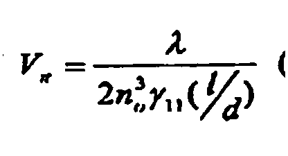
- the electrooptic Q-switch utilizes the transversal electrooptic effect of the crystal, and the half-voltage V ⁇ can be adjusted by changing the aspect ratio l / d , according to the formula of ( ⁇ is the wavelength of the laser, n o is the refractive index of the o light, l/d is the ratio of the length along the direction of the light propagation to the thickness along the direction of the electric field applied to the crystal, called aspect ratio.).
- the LGS crystal also possesses optical activity, which makes it difficult to design the Q-switch.
- the light propagates along the optic axis, and the plane polarized light goes forwards and backwards through the LGS crystal in the laser resonant cavity, so that the total angle of the polarization plane rotation is zero.
- the design avoids the influence of the optical activity on the polarized plane rotation of plane polarized light propagation in the crystal.
- the Q-switch works utilizing the orthogonal polarized light interference.
- the hardness of the LGS crystal is 5.5 (Mohs hardness), no cleavage, without any phase transformation point between the room temperature and its melting point 1470°C.
- the crystal is non- deliquescent, so moisture protection is not required.
- a wave plate of ⁇ / 4 can be installed in between the LGS crystal and the reflecting element. If a plane polarized light passes through the LGS crystal, its polarized direction will rotate a angle of ⁇ . Then it passes through the wave plate of ⁇ / 4, and is reflected back to the wave plate again by the reflecting element. It finally takes the same polarized direction as before it entered the wave plate of ⁇ / 4, and only the phase of the plane polarized light is changed for ⁇ / 2.
- the rotation direction for either left-rotating or right-rotating polarized light will be opposite to the rotating direction when it penetrated through the LGS crystal at first, because at present the LGS crystal Q-switch is closed and no electric field is applied.
- the plane polarized light composed of the left-rotating and right-rotating polarized light is out of the LGS crystal, its polarized direction will be the same as that when it first entered the LGS crystal, only the phase of the plane polarized light is changed by ⁇ / 2. This is equivalent to converting the parallel polarization light interference into the orthogonal polarization light interference.
- the orthogonal polarized light interference can avoid the influence of electrooptic effect on optical activity, because electric field is not applied on the LGS crystal when the Q-switch is closed.
- the propagation light is still to be plane polarized after it goes forwards and backwards through the optical active crystal.
- the property of the small birefringence of LGS crystal is utilized. The influences of the small mis-orientation and the optical inhomogeneity on the Q-switch are reduced to a small extent.
- the transmittance of the Q-switch at 1.064 ⁇ m may be up to 99%.
- the electrooptic Q-switch made of the LGS crystal possesses many advantages, such as high optical damage threshold (9.5 times of that of LN crystal), low and adjustable half-wave voltage, non-deliquescence, small half-wave voltage variation with temperature. It is very suitable for use in the intermediate power laser.
- the electrooptic Q-switch device was fabricated with LGS crystal 1 and reflecting element 2 placed at one side of LGS crystal 1 to reflect the laser beam back to LGS crystal 1.
- the plane polarized laser beam passes through the LGS crystal twice, forwards and backwards, so that the rotation angle of the polarization plane of the beam is zero.
- a plane polarized laser beam propagates through an optical active crystal, its polarization plane will rotate an angle of ⁇ around the wave vector K .
- the rotating direction is dependent on the wave vector K .
- the optical activity effect of LGS crystal vanishes. So, the misunderstanding that the optical active crystal could not be used for the electrooptic Q-switch device is eliminated.
- transversal electrooptic effect of LGS crystal 1 was used.
- the half-wave voltage can be adjusted by the ratio of longitudinal to transversal length of LGS crystal and the voltage changes slightly with the change of temperature. It is not necessary to consider moisture-protection.
- the laser damage threshold of LGS crystal is 9.5 times of that of LiNbO 3 (LN) crystal.
- the electrooptic Q-switch of LGS crystal has the common advantages of the switches of DKDP and LN crystals and it is particularly suitable for use in lasers of intermediate power.
- a 1/4 ⁇ wave plate 4 is placed between LGS crystal 1 and reflecting element 2, where ⁇ is the wavelength of laser beam.
- Fig. 1 is the schematic diagram of LGS Q-switch in a pulse laser.
- the laser beam with wavelength of 1.064 ⁇ m from Nd:YAG is linearly polarized by a polarizer 7.
- the polarization direction is the same as the X-axis of LGS.
- the polarization direction of the beam will rotate an angle of ⁇ , if the beam passes through the LGS crystal.
- the polarization direction does not change, but the phase of the beam changes by ⁇ /2.
- the Q-switch is in the situation of shut off
- the right-rotating polarization beam and the left-rotating polarization beam passing through the LGS crystal have the opposite rotating direction of polarization plane.
- the polarization direction remains unchanged but the phase of the beam changes by ⁇ /2.
- the parallel polarization interference is changed into the vertical polarization interference by this way.
- the vertical polarization interference without electric field applied on the LGS crystal prevents optical activity and ensures that the polarization direction does not change after the beam passes through the LGS crystal twice.
- This utilizes fully the advantage of the small birefringence of optical active LGS crystal and reduces the influence of orientated error and optical inhomogeneity on the Q-switch. This also makes the Q-switch have lower dynamic extinction ratio than static-state extinction ratio.
- the mentioned reflecting element 2 is a plane full-reflection-mirror.
- the end faces of the LGS crystal perpendicular to propagation direction are polished and coated with anti-reflection film at the wavelength 1.064 ⁇ m.
- the transmission of coated LGS crystal at 1.064 ⁇ m may be more than 99%.
- Laser beam propagates along Z-axis. An electric field was applied parallel to Y-axis.
- the LGS Q-switch can work effectively with the half-wave voltage 2250V in a Nd:YAG laser with a pulse output energy of 350mJ at repetition rates of 1Hz or 10Hz.
Landscapes
- Physics & Mathematics (AREA)
- Nonlinear Science (AREA)
- General Physics & Mathematics (AREA)
- Optics & Photonics (AREA)
- Chemical & Material Sciences (AREA)
- Crystallography & Structural Chemistry (AREA)
- Lasers (AREA)
- Optical Modulation, Optical Deflection, Nonlinear Optics, Optical Demodulation, Optical Logic Elements (AREA)
- Measuring Instrument Details And Bridges, And Automatic Balancing Devices (AREA)
- Crystals, And After-Treatments Of Crystals (AREA)
Abstract
Description
- Technology field attribution: This invention involves the application of crystal materials in the field of electrooptic technology. Actually, it will introduce a new electrooptic Q-switch made of a langasite single crystal.
- Technology background: Electrooptic Q-switch is an important optical element in laser technology. As long as a crystal can be used for electrooptic element, it must have the following physical properties: 1). Large electrooptic coefficient and low half-wave voltage; 2). High damage threshold; 3). Suitable transmission wavelength range; 4). High electrical resistance; 5). Low dielectric constant; 6). Stable physical and chemical properties. Up to date, only two kinds of electrooptic Q-switches are available in commercial market. They are made of DKDP and LiNbO3 crystals respectively. The former have high damage threshold and good optical homogeneity. When its longitudinal electrooptic effect is utilized in an electrooptic Q-switch, a circular electrical pole must be coated on the crystal. It becomes difficult to fabricate the electrooptic Q-switch. Another disadvantage of using a DKDP electrooptic Q-switch is its high and un-adjustable half-wave voltage which changes greatly with temperature. Furthermore, DKDP crystal is deliquescent, and so moisture protection must be considered. Thus the element fabrication process is very complicated. An advantage of using LiNbO3 as an electrooptic Q-switch is that its half-wave voltage is adjustable with the ratio of longitudinal to transversal length of crystal. Also, the transversal electrooptic effect is utilized when the crystal is used in an electrooptic Q-switch. It is very convenient to fabricate the electrooptic Q-switch using a LiNbO3 crystal. The disadvantages of using LiNbO3 in an electrooptic Q-switch include: low threshold, low optical homogeneity, large half-wave voltage variation with temperature at low temperature condition. Therefore, the above mentioned two kinds of crystal Q-switch elements can only meet the requirement of application to some extent. It is necessary to exploit new electrooptic crystals and Q-switch elements.
- Langasite (La3Ga5SiO14, abbreviated as LGS) is a piezoelectric crystal with good physical properties. In 1982, the laser expert A.A.Kaminsky reported the laser property of Nd:LGS crystal (A.A.Kaminsky, S.E.Sarkisov, Reports of the USSR Academy of Science, 1982, 264(1):93) for the first time. Later, growth and laser properties of Nd:LGS, Nd:Ca3Ga2Ge4O14 and Sr3Ga2Ge4O14 (A.A.Kaminsky, B.V.Mill, G.G.Khodzhabagyan, Phys.Stat.Sol.(a), 1983,80:387; A.A.Kaminsky, I.M.Silvestroval, S.E.Sarkisov, Phys.Stat.Sol.(a),1983,80:607; A.A.Kaminsky, E.L.Belokoneva, B.V.Mill, Phys.Stat.Sol.(a),1984,86:345) were reported. In 1984, A.I.Andreev discovered for the first time (A.I.Andreev, M.F.Doubvik, Letters to J. Theory Physics, 1984,10(8):487) that the elastic vibration for LGS single crystal possessed zero temperature coefficient cut-type. In 1986, SAW single chip filter and resonance device with high stability were fabricated by E.G.Bronnikova et al. (E.G.Gronnikova, I.M.Larionov, Electronic Engineering Series, "Radiodetails and Compounds",1986,2:63.). The patent for single chip LGS crystal filter was applied by S.A.Sarkissov et al. (Patent see patent application publication SU1780147) and it symbolized that application aspect is exploited. Later, scientists from America, Germany, Japan and Korea paid attention to this work and extensive studies on the LGS family crystals were performed. At present, in addition to scientists from Russia, scientists from Japan joined in this research and some companies tried to exploit the related device. Scientists from China also paid attention to the research and application of the crystal. (Hu Shaoqin, Piezoelectricity and acoustic-optics, 1999,21(4):299). Up to now, the application of LGS and its family crystals in electrooptic device is still not reported in the world.
- Electrooptic property results in the change of refractive index affected by electric field. Electrooptic Q-switch and electrooptic modulator can be fabricated by utilizing the electrooptic effect. LGS family crystals (32 point group symmetry) possess both electrooptic effect and optical activity. Optical activity means that the polarization plane will rotate an angle proportional to the crystal thickness when a monochromic plane wave propagates through a crystal. The interaction between electrooptic effect and optical activity was studied. It is thought that the fabrication of an electrooptic device using a crystal with optical active property is difficult due to the polarization plane rotation affected by optical activity. Therefore, no electrooptic devices fabricated using crystals with optical activity have been reported up to now.
- A Q-switch comprised of a quarter wave plate, a pockels cell and a polarizer included in a resonant laser cavity is known from the US 52 72 713 patent specification.
- According to the present invention, there is provided a Q-switch element according to
claim 1. - The result of the invention is to provide a new electrooptic Q-switch made of a single crystal with optical activity. It overcomes the disadvantages of commercial electrooptic Q-switches such as high, un-adjustable half-wave voltage, low stability with temperature, low optical damage threshold and deliquescence.
- In an embodiment of the invention, a new electrooptic Q-switch includes a rectangular piece of langasite (La3Ga5SiO14) crystal and a reflecting element located on one side of the LGS crystal along the light propagation direction. The linear polarized light passing through the LGS crystal can be reflected by the reflecting element, then returns the LGS crystal again, and the angle of the polarization plane rotation becomes zero.
- In an embodiment of the invention, a wave plate of λ/4 is installed in between the LGS crystal and the reflecting element where λ is the wavelength of the propagation light in LGS.
- In embodiments of the invention, the langasite crystal can be LGS, or Nd-doped LGS, or La3Ga5-xAlxSiO14 (the value of x is 0-5), or Sr3Ga2Ge4O14, or Na2CaGe6O14, or Ca3Ga2Ge4O14, or La3Ga5.5Nb0.5O14, or La3Ga5.5Ta0.5O14 crystal.
- In an embodiment of the invention, two end faces of the LGS crystal perpendicular to the direction of the light must be polished and coated with anti-reflection films for 1.064 µm laser.
- In particular, the length along the Z direction (the light propagation direction) of the LGS crystal ranges from 8mm to 1500mm, and the width (along X or Y direction) and thickness (along X or Y direction) perpendicular to the direction of the length ranges from 4mm to 20mm.
- In addition, two end faces of the LGS crystal along the direction of the light propagation may be processed to be the Brewster's angle and polished. The Brewster's angle is 62°for the 1.064µm laser. And the length of Z direction of the LGS crystal ranges from 8mm to 1500mm, the width along the X direction ranges from 4mm to 15mm, and the thickness along the Y direction ranges from 4 to 15mm. The electric field is applied along the Y direction.
- The reflecting element mentioned above can be an all-reflection plane mirror.
- The electrooptic Q-switch designed in this invention is more suitable for the medium power laser widely used at present. The main advantage of the invention is that the optical activity of the LGS crystal is prevented from influencing the electrooptic property. Based on the efficient electrooptic coefficients and optic damage threshold of LGS crystal, a new electrooptic Q-switch, possessing the advantages of low, adjustable half-wave voltage, high stability with temperature, high optical damage threshold and non-deliquescent, has been designed and successfully fabricated by utilizing the transversal electrooptic effect of the crystal.
- The LGS crystal belongs to the trigonal system, with point group 32, and possesses electrooptic effect and optical activity. The electrooptic coefficients of the LGS crystal are γ11=γ12=γ62=2.3×10⁻¹²m/V, and the optic damage threshold is 9.5 times of that of the LiNbO3 crystal. The results above show the LGS crystal can be used to fabricate the electrooptic Q-switch. The electrooptic Q-switch utilizes the transversal electrooptic effect of the crystal, and the half-voltage Vπ can be adjusted by changing the aspect ratio l / d, according to the formula of(λ is the wavelength of the laser, no is the refractive index of the o light, l/d is the ratio of the length along the direction of the light propagation to the thickness along the direction of the electric field applied to the crystal, called aspect ratio.).
- Besides the electrooptic effect, the LGS crystal also possesses optical activity, which makes it difficult to design the Q-switch. In this invention, the light propagates along the optic axis, and the plane polarized light goes forwards and backwards through the LGS crystal in the laser resonant cavity, so that the total angle of the polarization plane rotation is zero. The design avoids the influence of the optical activity on the polarized plane rotation of plane polarized light propagation in the crystal. The Q-switch works utilizing the orthogonal polarized light interference.
- In addition, the hardness of the LGS crystal is 5.5 (Mohs hardness), no cleavage, without any phase transformation point between the room temperature and its melting point 1470°C. The crystal is non- deliquescent, so moisture protection is not required.
- In an embodiment of the invention, a wave plate of λ / 4 can be installed in between the LGS crystal and the reflecting element. If a plane polarized light passes through the LGS crystal, its polarized direction will rotate a angle of ϕ. Then it passes through the wave plate of λ / 4, and is reflected back to the wave plate again by the reflecting element. It finally takes the same polarized direction as before it entered the wave plate of λ / 4, and only the phase of the plane polarized light is changed for π / 2. When the light goes back through the LGS crystal, the rotation direction for either left-rotating or right-rotating polarized light will be opposite to the rotating direction when it penetrated through the LGS crystal at first, because at present the LGS crystal Q-switch is closed and no electric field is applied. Eventually when the plane polarized light composed of the left-rotating and right-rotating polarized light is out of the LGS crystal, its polarized direction will be the same as that when it first entered the LGS crystal, only the phase of the plane polarized light is changed by π / 2. This is equivalent to converting the parallel polarization light interference into the orthogonal polarization light interference. Compared with the parallel polarization light interference, the orthogonal polarized light interference can avoid the influence of electrooptic effect on optical activity, because electric field is not applied on the LGS crystal when the Q-switch is closed. The propagation light is still to be plane polarized after it goes forwards and backwards through the optical active crystal. Also, the property of the small birefringence of LGS crystal is utilized. The influences of the small mis-orientation and the optical inhomogeneity on the Q-switch are reduced to a small extent.
- In this embodiment of the invention, because two end faces of the LGS Q-switch along the light propagation direction can be polished and coated with anti-reflection films for 1.064µm laser, the transmittance of the Q-switch at 1.064µm may be up to 99%.
- Summarized in the description above, the electrooptic Q-switch made of the LGS crystal possesses many advantages, such as high optical damage threshold (9.5 times of that of LN crystal), low and adjustable half-wave voltage, non-deliquescence, small half-wave voltage variation with temperature. It is very suitable for use in the intermediate power laser.
-
- Fig. 1. Principle of the electrooptic Q-switch in an embodiment of this invention.
- Fig. 2. Schematic diagram of the structure of LGS electrooptic Q-switch in an embodiment of this invention.
-
- As shown in Fig.1 and Fig.2, the electrooptic Q-switch device was fabricated with
LGS crystal 1 and reflectingelement 2 placed at one side ofLGS crystal 1 to reflect the laser beam back toLGS crystal 1. The plane polarized laser beam passes through the LGS crystal twice, forwards and backwards, so that the rotation angle of the polarization plane of the beam is zero. As mentioned above, when a plane polarized laser beam propagates through an optical active crystal, its polarization plane will rotate an angle of Φ around the wave vector K. The rotating direction is dependent on the wave vector K. When the beam is reflected back to propagate the same distance along the wave vector -K, the rotation angle will be -Φ. So Φ+(-Φ)=0. As a result, the optical activity effect of LGS crystal vanishes. So, the misunderstanding that the optical active crystal could not be used for the electrooptic Q-switch device is eliminated. In this invention, transversal electrooptic effect ofLGS crystal 1 was used. The half-wave voltage can be adjusted by the ratio of longitudinal to transversal length of LGS crystal and the voltage changes slightly with the change of temperature. It is not necessary to consider moisture-protection. The laser damage threshold of LGS crystal is 9.5 times of that of LiNbO3 (LN) crystal. The electrooptic Q-switch of LGS crystal has the common advantages of the switches of DKDP and LN crystals and it is particularly suitable for use in lasers of intermediate power. - In an embodiment of this invention, as shown in Fig.1, a 1/4
λ wave plate 4 is placed betweenLGS crystal 1 and reflectingelement 2, where λ is the wavelength of laser beam. Fig. 1 is the schematic diagram of LGS Q-switch in a pulse laser. The laser beam with wavelength of 1.064 µm from Nd:YAG is linearly polarized by apolarizer 7. The polarization direction is the same as the X-axis of LGS. The polarization direction of the beam will rotate an angle of , if the beam passes through the LGS crystal. After the beam passes through the λ/4wave plate 4, and is reflected by the reflectingelement 2, and passes through thewave plate 4 again, the polarization direction does not change, but the phase of the beam changes by π/2. When no electric field is applied to the LGS crystal, i.e. the Q-switch is in the situation of shut off, the right-rotating polarization beam and the left-rotating polarization beam passing through the LGS crystal have the opposite rotating direction of polarization plane. After the beam passes through LGS twice, the polarization direction remains unchanged but the phase of the beam changes by π/2. The parallel polarization interference is changed into the vertical polarization interference by this way. Compared with the parallel polarization interference, the vertical polarization interference without electric field applied on the LGS crystal prevents optical activity and ensures that the polarization direction does not change after the beam passes through the LGS crystal twice. This utilizes fully the advantage of the small birefringence of optical active LGS crystal and reduces the influence of orientated error and optical inhomogeneity on the Q-switch. This also makes the Q-switch have lower dynamic extinction ratio than static-state extinction ratio. - As shown in Fig. 1, the mentioned reflecting
element 2 is a plane full-reflection-mirror. - In this invention, the mentioned LGS crystal generally refers to La3Ga5SiO14, Nd:La3Ga5SiO14, La3Ga5-xAlxSiO14(x=0~5), Sr3Ga2Ge4O14, Na2GaGe6O14, Ca3Ga2Ge4O14, La3Ga5.5Nb0.sO14, La3Ga5.5Ta0.5O14 crystal, and other isomorphic heterogeneous crystals of LGS.
- In order to increase the transmission of the mentioned LGS crystal, the end faces of the LGS crystal perpendicular to propagation direction are polished and coated with anti-reflection film at the wavelength 1.064µm. The transmission of coated LGS crystal at 1.064µm may be more than 99%.
- As shown in Fig.2, the LGS crystal can be processed with the length l=8mm~1500mm at Z-axis direction which is the propagation direction of laser beam, thickness d=4mm~20mm at X- or Y-axis direction, width w=4mm~20mm which is perpendicular to the length and the thickness. For example, the size of a LGS crystal Q-switch is l=40.3mm at Z-axis direction, d=6.12mm at Y-axis direction, w=6.12mm at X-axis direction. Laser beam propagates along Z-axis. An electric field was applied parallel to Y-axis. The LGS Q-switch can work effectively with the half-wave voltage 2250V in a Nd:YAG laser with a pulse output energy of 350mJ at repetition rates of 1Hz or 10Hz.
Claims (6)
- An electrooptic Q-switch device, which comprises an electrooptic single crystal (1) a reflection element (2) reflection element being arranged on one side of the electrooptic single crystal along a direction defined by the optical axis of the electrooptic single crystal, the electrooptic Q-switch device being arranged to receive a linearly polarized light beam at a side of the electrooptic single crystal opposite to the one where said reflection element is disposed, the light beam propagation direction being parallel to the optical axis of the electrooptic single crystal, characterized in that said electrooptic single crystal is a rectangularly shaped langasite-type (LGS) optically active single crystal, and in that the device is arranged such that an incident light beam (3) propogating through the langasite type single crystal along the optical axis is reflected by said reflection element and passes through said langasite-type single crystal along the optical axis again in order to eliminate the rotation of the polarization of the light beam originated from the optical activity of said langasite-type single crystal.
- The electrooptic Q-switch device of claim 1 in which a λ/4 wave-plate (4) is installed between the langasite-type single crystal and the reflection element, λ being the wavelength of the light beam propagating in the langasite-type single crystal.
- The electrooptic Q-switch device of claim 1 or 2 in which the langasite-type single crystal is a La3Ca5SiO14 crystal, or a Nd doped La3Ga5SiO14 crystal, or a La3Ga5-xAlxSiO14 crystal (x ranges from 0 to 5), or a Sr3Ga2Ge4O14 crystal, or a Na2CaGe6O14 crystal, or a Ca3Ga2Ge4O14 crystal, or a La3Ga5.5Nb0.5O14 crystal, or a La3Ga5.5Ta0.5O14 crystal.
- The electrooptic Q-switch device of one of the preceding claims in which said langasite-type single crystal possesses two end faces along the main optical axis which are polished and coated with anti-reflection films for a wavelength of 1.064 µm.
- The electrooptic Q-switch device of one of the preceding claims in which the length of the langasite-type single crystal along the light propagation or z direction ranges from 8 to 1500mm, and in which the thickness of the langasite-type single crystal in x or y directions orthogonal to said a direction ranges from 4 to 20 mm respectively.
- The electrooptic Q-switch device of claim 1 in which the reflection element is a plane mirror with fall reflection at a wavelength of the light beam passing through said electrooptic langasite single crystal.
Applications Claiming Priority (2)
| Application Number | Priority Date | Filing Date | Title |
|---|---|---|---|
| CN02110374 | 2002-05-20 | ||
| CNB021103747A CN1166039C (en) | 2002-05-20 | 2002-05-20 | Crystal electro-optical Q switch device |
Publications (3)
| Publication Number | Publication Date |
|---|---|
| EP1365275A2 EP1365275A2 (en) | 2003-11-26 |
| EP1365275A3 EP1365275A3 (en) | 2003-12-03 |
| EP1365275B1 true EP1365275B1 (en) | 2005-12-28 |
Family
ID=4741057
Family Applications (1)
| Application Number | Title | Priority Date | Filing Date |
|---|---|---|---|
| EP03252841A Expired - Lifetime EP1365275B1 (en) | 2002-05-20 | 2003-05-07 | Electro-optic Q-switch with Langasite-type single crystal |
Country Status (6)
| Country | Link |
|---|---|
| US (1) | US7130318B2 (en) |
| EP (1) | EP1365275B1 (en) |
| JP (1) | JP3961448B2 (en) |
| CN (1) | CN1166039C (en) |
| AT (1) | ATE314678T1 (en) |
| DE (1) | DE60302930T2 (en) |
Families Citing this family (20)
| Publication number | Priority date | Publication date | Assignee | Title |
|---|---|---|---|---|
| CN1166039C (en) * | 2002-05-20 | 2004-09-08 | 山东大学 | Crystal electro-optical Q switch device |
| CN1302586C (en) * | 2004-02-27 | 2007-02-28 | 山东大学 | Multi-block crystal electrooptical Q-switch device |
| JP5189738B2 (en) * | 2005-03-29 | 2013-04-24 | ジェイディーエス ユニフェイズ コーポレーション | Stabilization of active Q-switched laser |
| WO2006106875A1 (en) * | 2005-03-30 | 2006-10-12 | Fukuda Crystal Laboratory | Gallate single crystal, process for producing the same, piezoelectric device for high-temperature use and piezoelectric sensor for high-temperature use |
| US20080002751A1 (en) * | 2005-08-10 | 2008-01-03 | Gongxue Hua | High damage threshold Q-switched CO2 laser |
| CN100452576C (en) * | 2005-11-28 | 2009-01-14 | 深圳市大族激光科技股份有限公司 | Air-cooled electro-optic Q switch |
| US7522642B2 (en) * | 2006-03-29 | 2009-04-21 | Amo Development Llc | Method and system for laser amplification using a dual crystal Pockels cell |
| CN101662121B (en) * | 2009-09-22 | 2011-05-04 | 青岛海泰光电技术有限公司 | Processing methods of matched crystals used in laser Q-switching device |
| CN101719626B (en) * | 2009-11-06 | 2011-01-19 | 华中科技大学 | Electric-optically Q-switched laser resonator |
| CN101719627B (en) * | 2009-11-06 | 2011-01-19 | 华中科技大学 | Electro-optical Q-switched laser resonator |
| CN101847975B (en) * | 2010-03-31 | 2012-08-08 | 山东大学 | NdCa4O(BO3)3 Crystal Zero Frequency Temperature Coefficient Cut Shape and Its Application |
| CN102570282A (en) * | 2012-02-17 | 2012-07-11 | 北京工业大学 | Device and method for increasing linearly polarized light output power of neodymium (Nd): yttrium aluminum garnet (YAG) laser |
| KR20130120923A (en) * | 2012-04-26 | 2013-11-05 | 원텍 주식회사 | Drive device for q-switching element |
| CN102780148B (en) * | 2012-06-29 | 2014-11-26 | 中国电子科技集团公司第十一研究所 | Intracavity pump laser using complex cavity |
| CN103259182B (en) * | 2013-04-26 | 2014-06-18 | 山东大学 | General electro-optical Q-switching switch and Q-switching laser for broadband passing through optical rotation crystal for single or odd times |
| WO2017120717A1 (en) * | 2016-01-11 | 2017-07-20 | 中国科学院国家授时中心 | Electro-optic phase modulation system |
| CN106159666A (en) * | 2016-09-20 | 2016-11-23 | 福建福晶科技股份有限公司 | A kind of new type electro Q-switch |
| CN108321672B (en) * | 2018-03-12 | 2020-06-23 | 中国科学院苏州生物医学工程技术研究所 | A High Peak Power Holmium Laser System |
| CN112803224A (en) * | 2021-01-19 | 2021-05-14 | 山东大学 | Mid-infrared band difference frequency laser based on gallium-lanthanum niobate crystal |
| CN115185137B (en) * | 2022-08-17 | 2024-10-08 | 山东大学 | Effective nonlinear optical coefficient optimization method for gallium-lanthanum silicate solid solution crystal |
Family Cites Families (7)
| Publication number | Priority date | Publication date | Assignee | Title |
|---|---|---|---|---|
| US3815046A (en) * | 1973-02-07 | 1974-06-04 | Atomic Energy Commission | Synchronously driven q-switched or q-switched-mode-locked laser oscillator |
| US3828276A (en) * | 1973-05-25 | 1974-08-06 | Quantronix Corp | High efficiency acousto-optical q-switch |
| JPH01259266A (en) * | 1988-04-08 | 1989-10-16 | Hamamatsu Photonics Kk | Voltage measuring instrument |
| US5272713A (en) * | 1992-08-27 | 1993-12-21 | Spectra-Physics Lasers, Inc. | High repetition rate pulsed laser |
| US5384798A (en) * | 1992-12-03 | 1995-01-24 | Energy Compression Research Corp. | Photocondutively controlled electro-optic laser modulation |
| JP3542014B2 (en) * | 1998-09-21 | 2004-07-14 | セントラル硝子株式会社 | Method for producing single-crystal or polycrystal-containing amorphous material and amorphous material thereof |
| CN1166039C (en) * | 2002-05-20 | 2004-09-08 | 山东大学 | Crystal electro-optical Q switch device |
-
2002
- 2002-05-20 CN CNB021103747A patent/CN1166039C/en not_active Expired - Fee Related
-
2003
- 2003-05-07 DE DE60302930T patent/DE60302930T2/en not_active Expired - Lifetime
- 2003-05-07 EP EP03252841A patent/EP1365275B1/en not_active Expired - Lifetime
- 2003-05-07 AT AT03252841T patent/ATE314678T1/en not_active IP Right Cessation
- 2003-05-16 JP JP2003138878A patent/JP3961448B2/en not_active Expired - Lifetime
- 2003-05-20 US US10/441,404 patent/US7130318B2/en not_active Expired - Lifetime
Also Published As
| Publication number | Publication date |
|---|---|
| DE60302930D1 (en) | 2006-02-02 |
| ATE314678T1 (en) | 2006-01-15 |
| DE60302930T2 (en) | 2006-08-24 |
| US20030214983A1 (en) | 2003-11-20 |
| EP1365275A2 (en) | 2003-11-26 |
| EP1365275A3 (en) | 2003-12-03 |
| JP3961448B2 (en) | 2007-08-22 |
| CN1402391A (en) | 2003-03-12 |
| US7130318B2 (en) | 2006-10-31 |
| JP2003347635A (en) | 2003-12-05 |
| CN1166039C (en) | 2004-09-08 |
Similar Documents
| Publication | Publication Date | Title |
|---|---|---|
| EP1365275A2 (en) | Electro-optic Q-switch with Langasite-type single crystal | |
| Nash et al. | Optical nonlinearities in LiIO3 | |
| Bosshard et al. | Kerr nonlinearity via cascaded optical rectification and the linear electro-optic effect | |
| US5107509A (en) | Tunable solid state laser with high wavelength selectivity over a preselected wavelength range | |
| CN103135261B (en) | Electro-optic isolator and manufacturing method thereof | |
| US20040001255A1 (en) | Polarization compensators and optical devices and systems incorporating polarization compensators | |
| EP0615319A2 (en) | Quasi-monolithic saturable optical element | |
| EP1737088B1 (en) | Multipath laser apparatus using a solid-state laser rod | |
| US6859467B2 (en) | Electro-optic modulator material | |
| US6625186B1 (en) | Laser frequency doubling device of ReCa4O(BO3)3 crystal with specific cut angles | |
| CN1057616C (en) | Increasing the birefringence of ktp and its isomorphs for type II phase matching | |
| EP2930798A1 (en) | Plane waveguide-type laser device | |
| Breguet et al. | Electrooptically Q-switched 2.79 mu m YSGG: Cr: Er laser with an intracavity polarizer | |
| Il'ichev et al. | Influence of the nonlinear anisotropy of absorption in a passive Cr4+: YAG switch on the energy and polarisation characteristics of a neodymium laser | |
| CN107132673B (en) | A device for eliminating depolarization of electro-optical crystals | |
| RU203208U1 (en) | Monopulse solid state laser | |
| Romani et al. | Evaluation of the effective second harmonic generation coefficient of monomethyl urea single crystals | |
| US5264959A (en) | Temperature-insensitive phase-matched optical harmonic conversion crystal | |
| Bagan et al. | Characteristics of Cornu depolarisers made from quartz and paratellurite optically active crystals | |
| JPH05235457A (en) | Ld excited shg laser apparatus | |
| Shimazu* et al. | Phase-matching of optically second-harmonic generation in the single crystals of Gd-and La-added barium sodium niobate | |
| Roth et al. | RTP crystals for electro-optic Q-switching | |
| Roth et al. | Oxide Crystals for Electro-optic Q-switching | |
| Pracka et al. | Lithium niobate as an effective material for manufacturing of electro-optic modulators | |
| Adams et al. | Electro-optic modulator material |
Legal Events
| Date | Code | Title | Description |
|---|---|---|---|
| PUAI | Public reference made under article 153(3) epc to a published international application that has entered the european phase |
Free format text: ORIGINAL CODE: 0009012 |
|
| PUAL | Search report despatched |
Free format text: ORIGINAL CODE: 0009013 |
|
| 17P | Request for examination filed |
Effective date: 20030528 |
|
| AK | Designated contracting states |
Kind code of ref document: A2 Designated state(s): AT BE BG CH CY CZ DE DK EE ES FI FR GB GR HU IE IT LI LU MC NL PT RO SE SI SK TR |
|
| AX | Request for extension of the european patent |
Extension state: AL LT LV MK |
|
| AK | Designated contracting states |
Kind code of ref document: A3 Designated state(s): AT BE BG CH CY CZ DE DK EE ES FI FR GB GR HU IE IT LI LU MC NL PT RO SE SI SK TR |
|
| AX | Request for extension of the european patent |
Extension state: AL LT LV MK |
|
| 17Q | First examination report despatched |
Effective date: 20040519 |
|
| AKX | Designation fees paid |
Designated state(s): AT BE BG CH CY CZ DE DK EE ES FI FR GB GR HU IE IT LI LU MC NL PT RO SE SI SK TR |
|
| GRAP | Despatch of communication of intention to grant a patent |
Free format text: ORIGINAL CODE: EPIDOSNIGR1 |
|
| GRAS | Grant fee paid |
Free format text: ORIGINAL CODE: EPIDOSNIGR3 |
|
| GRAA | (expected) grant |
Free format text: ORIGINAL CODE: 0009210 |
|
| AK | Designated contracting states |
Kind code of ref document: B1 Designated state(s): AT BE BG CH CY CZ DE DK EE ES FI FR GB GR HU IE IT LI LU MC NL PT RO SE SI SK TR |
|
| PG25 | Lapsed in a contracting state [announced via postgrant information from national office to epo] |
Ref country code: IT Free format text: LAPSE BECAUSE OF FAILURE TO SUBMIT A TRANSLATION OF THE DESCRIPTION OR TO PAY THE FEE WITHIN THE PRESCRIBED TIME-LIMIT;WARNING: LAPSES OF ITALIAN PATENTS WITH EFFECTIVE DATE BEFORE 2007 MAY HAVE OCCURRED AT ANY TIME BEFORE 2007. THE CORRECT EFFECTIVE DATE MAY BE DIFFERENT FROM THE ONE RECORDED. Effective date: 20051228 Ref country code: AT Free format text: LAPSE BECAUSE OF FAILURE TO SUBMIT A TRANSLATION OF THE DESCRIPTION OR TO PAY THE FEE WITHIN THE PRESCRIBED TIME-LIMIT Effective date: 20051228 Ref country code: CH Free format text: LAPSE BECAUSE OF FAILURE TO SUBMIT A TRANSLATION OF THE DESCRIPTION OR TO PAY THE FEE WITHIN THE PRESCRIBED TIME-LIMIT Effective date: 20051228 Ref country code: SI Free format text: LAPSE BECAUSE OF FAILURE TO SUBMIT A TRANSLATION OF THE DESCRIPTION OR TO PAY THE FEE WITHIN THE PRESCRIBED TIME-LIMIT Effective date: 20051228 Ref country code: LI Free format text: LAPSE BECAUSE OF FAILURE TO SUBMIT A TRANSLATION OF THE DESCRIPTION OR TO PAY THE FEE WITHIN THE PRESCRIBED TIME-LIMIT Effective date: 20051228 Ref country code: BE Free format text: LAPSE BECAUSE OF FAILURE TO SUBMIT A TRANSLATION OF THE DESCRIPTION OR TO PAY THE FEE WITHIN THE PRESCRIBED TIME-LIMIT Effective date: 20051228 Ref country code: SK Free format text: LAPSE BECAUSE OF FAILURE TO SUBMIT A TRANSLATION OF THE DESCRIPTION OR TO PAY THE FEE WITHIN THE PRESCRIBED TIME-LIMIT Effective date: 20051228 Ref country code: RO Free format text: LAPSE BECAUSE OF FAILURE TO SUBMIT A TRANSLATION OF THE DESCRIPTION OR TO PAY THE FEE WITHIN THE PRESCRIBED TIME-LIMIT Effective date: 20051228 Ref country code: FI Free format text: LAPSE BECAUSE OF FAILURE TO SUBMIT A TRANSLATION OF THE DESCRIPTION OR TO PAY THE FEE WITHIN THE PRESCRIBED TIME-LIMIT Effective date: 20051228 Ref country code: NL Free format text: LAPSE BECAUSE OF FAILURE TO SUBMIT A TRANSLATION OF THE DESCRIPTION OR TO PAY THE FEE WITHIN THE PRESCRIBED TIME-LIMIT Effective date: 20051228 Ref country code: CZ Free format text: LAPSE BECAUSE OF FAILURE TO SUBMIT A TRANSLATION OF THE DESCRIPTION OR TO PAY THE FEE WITHIN THE PRESCRIBED TIME-LIMIT Effective date: 20051228 |
|
| REG | Reference to a national code |
Ref country code: GB Ref legal event code: FG4D |
|
| REG | Reference to a national code |
Ref country code: CH Ref legal event code: EP |
|
| REG | Reference to a national code |
Ref country code: IE Ref legal event code: FG4D |
|
| REF | Corresponds to: |
Ref document number: 60302930 Country of ref document: DE Date of ref document: 20060202 Kind code of ref document: P |
|
| PG25 | Lapsed in a contracting state [announced via postgrant information from national office to epo] |
Ref country code: DK Free format text: LAPSE BECAUSE OF FAILURE TO SUBMIT A TRANSLATION OF THE DESCRIPTION OR TO PAY THE FEE WITHIN THE PRESCRIBED TIME-LIMIT Effective date: 20060328 Ref country code: BG Free format text: LAPSE BECAUSE OF FAILURE TO SUBMIT A TRANSLATION OF THE DESCRIPTION OR TO PAY THE FEE WITHIN THE PRESCRIBED TIME-LIMIT Effective date: 20060328 Ref country code: GR Free format text: LAPSE BECAUSE OF FAILURE TO SUBMIT A TRANSLATION OF THE DESCRIPTION OR TO PAY THE FEE WITHIN THE PRESCRIBED TIME-LIMIT Effective date: 20060328 Ref country code: SE Free format text: LAPSE BECAUSE OF FAILURE TO SUBMIT A TRANSLATION OF THE DESCRIPTION OR TO PAY THE FEE WITHIN THE PRESCRIBED TIME-LIMIT Effective date: 20060328 |
|
| PG25 | Lapsed in a contracting state [announced via postgrant information from national office to epo] |
Ref country code: ES Free format text: LAPSE BECAUSE OF FAILURE TO SUBMIT A TRANSLATION OF THE DESCRIPTION OR TO PAY THE FEE WITHIN THE PRESCRIBED TIME-LIMIT Effective date: 20060408 |
|
| PG25 | Lapsed in a contracting state [announced via postgrant information from national office to epo] |
Ref country code: IE Free format text: LAPSE BECAUSE OF NON-PAYMENT OF DUE FEES Effective date: 20060508 |
|
| PG25 | Lapsed in a contracting state [announced via postgrant information from national office to epo] |
Ref country code: PT Free format text: LAPSE BECAUSE OF FAILURE TO SUBMIT A TRANSLATION OF THE DESCRIPTION OR TO PAY THE FEE WITHIN THE PRESCRIBED TIME-LIMIT Effective date: 20060529 |
|
| PG25 | Lapsed in a contracting state [announced via postgrant information from national office to epo] |
Ref country code: MC Free format text: LAPSE BECAUSE OF NON-PAYMENT OF DUE FEES Effective date: 20060531 |
|
| NLV1 | Nl: lapsed or annulled due to failure to fulfill the requirements of art. 29p and 29m of the patents act | ||
| PG25 | Lapsed in a contracting state [announced via postgrant information from national office to epo] |
Ref country code: HU Free format text: LAPSE BECAUSE OF FAILURE TO SUBMIT A TRANSLATION OF THE DESCRIPTION OR TO PAY THE FEE WITHIN THE PRESCRIBED TIME-LIMIT Effective date: 20060629 |
|
| REG | Reference to a national code |
Ref country code: CH Ref legal event code: PL |
|
| ET | Fr: translation filed | ||
| PLBE | No opposition filed within time limit |
Free format text: ORIGINAL CODE: 0009261 |
|
| STAA | Information on the status of an ep patent application or granted ep patent |
Free format text: STATUS: NO OPPOSITION FILED WITHIN TIME LIMIT |
|
| 26N | No opposition filed |
Effective date: 20060929 |
|
| REG | Reference to a national code |
Ref country code: IE Ref legal event code: MM4A |
|
| PG25 | Lapsed in a contracting state [announced via postgrant information from national office to epo] |
Ref country code: EE Free format text: LAPSE BECAUSE OF FAILURE TO SUBMIT A TRANSLATION OF THE DESCRIPTION OR TO PAY THE FEE WITHIN THE PRESCRIBED TIME-LIMIT Effective date: 20051228 |
|
| PG25 | Lapsed in a contracting state [announced via postgrant information from national office to epo] |
Ref country code: LU Free format text: LAPSE BECAUSE OF NON-PAYMENT OF DUE FEES Effective date: 20060507 Ref country code: TR Free format text: LAPSE BECAUSE OF FAILURE TO SUBMIT A TRANSLATION OF THE DESCRIPTION OR TO PAY THE FEE WITHIN THE PRESCRIBED TIME-LIMIT Effective date: 20051228 |
|
| PG25 | Lapsed in a contracting state [announced via postgrant information from national office to epo] |
Ref country code: CY Free format text: LAPSE BECAUSE OF FAILURE TO SUBMIT A TRANSLATION OF THE DESCRIPTION OR TO PAY THE FEE WITHIN THE PRESCRIBED TIME-LIMIT Effective date: 20051228 |
|
| REG | Reference to a national code |
Ref country code: FR Ref legal event code: PLFP Year of fee payment: 14 |
|
| REG | Reference to a national code |
Ref country code: FR Ref legal event code: PLFP Year of fee payment: 15 |
|
| REG | Reference to a national code |
Ref country code: FR Ref legal event code: PLFP Year of fee payment: 16 |
|
| PGFP | Annual fee paid to national office [announced via postgrant information from national office to epo] |
Ref country code: GB Payment date: 20220510 Year of fee payment: 20 Ref country code: FR Payment date: 20220511 Year of fee payment: 20 Ref country code: DE Payment date: 20220531 Year of fee payment: 20 |
|
| REG | Reference to a national code |
Ref country code: DE Ref legal event code: R071 Ref document number: 60302930 Country of ref document: DE |
|
| REG | Reference to a national code |
Ref country code: GB Ref legal event code: PE20 Expiry date: 20230506 |
|
| PG25 | Lapsed in a contracting state [announced via postgrant information from national office to epo] |
Ref country code: GB Free format text: LAPSE BECAUSE OF EXPIRATION OF PROTECTION Effective date: 20230506 |