EP1365135A2 - A fuel injection control device - Google Patents
A fuel injection control device Download PDFInfo
- Publication number
- EP1365135A2 EP1365135A2 EP03011424A EP03011424A EP1365135A2 EP 1365135 A2 EP1365135 A2 EP 1365135A2 EP 03011424 A EP03011424 A EP 03011424A EP 03011424 A EP03011424 A EP 03011424A EP 1365135 A2 EP1365135 A2 EP 1365135A2
- Authority
- EP
- European Patent Office
- Prior art keywords
- fuel
- pressure wave
- fuel injection
- pressurized
- chamber
- Prior art date
- Legal status (The legal status is an assumption and is not a legal conclusion. Google has not performed a legal analysis and makes no representation as to the accuracy of the status listed.)
- Granted
Links
- 239000000446 fuel Substances 0.000 title claims abstract description 439
- 238000002347 injection Methods 0.000 title claims abstract description 174
- 239000007924 injection Substances 0.000 title claims abstract description 174
- 230000001902 propagating effect Effects 0.000 claims description 4
- 230000007423 decrease Effects 0.000 description 12
- 238000002485 combustion reaction Methods 0.000 description 5
- 238000013016 damping Methods 0.000 description 4
- 230000003247 decreasing effect Effects 0.000 description 4
- 239000002828 fuel tank Substances 0.000 description 2
- 230000006835 compression Effects 0.000 description 1
- 238000007906 compression Methods 0.000 description 1
- 230000004048 modification Effects 0.000 description 1
- 238000012986 modification Methods 0.000 description 1
Images


Classifications
-
- F—MECHANICAL ENGINEERING; LIGHTING; HEATING; WEAPONS; BLASTING
- F02—COMBUSTION ENGINES; HOT-GAS OR COMBUSTION-PRODUCT ENGINE PLANTS
- F02D—CONTROLLING COMBUSTION ENGINES
- F02D41/00—Electrical control of supply of combustible mixture or its constituents
- F02D41/30—Controlling fuel injection
- F02D41/38—Controlling fuel injection of the high pressure type
- F02D41/40—Controlling fuel injection of the high pressure type with means for controlling injection timing or duration
- F02D41/402—Multiple injections
- F02D41/403—Multiple injections with pilot injections
-
- F—MECHANICAL ENGINEERING; LIGHTING; HEATING; WEAPONS; BLASTING
- F02—COMBUSTION ENGINES; HOT-GAS OR COMBUSTION-PRODUCT ENGINE PLANTS
- F02D—CONTROLLING COMBUSTION ENGINES
- F02D41/00—Electrical control of supply of combustible mixture or its constituents
- F02D41/30—Controlling fuel injection
- F02D41/38—Controlling fuel injection of the high pressure type
- F02D41/3809—Common rail control systems
- F02D41/3836—Controlling the fuel pressure
- F02D41/3863—Controlling the fuel pressure by controlling the flow out of the common rail, e.g. using pressure relief valves
- F02D41/3872—Controlling the fuel pressure by controlling the flow out of the common rail, e.g. using pressure relief valves characterised by leakage flow in injectors
-
- F—MECHANICAL ENGINEERING; LIGHTING; HEATING; WEAPONS; BLASTING
- F02—COMBUSTION ENGINES; HOT-GAS OR COMBUSTION-PRODUCT ENGINE PLANTS
- F02D—CONTROLLING COMBUSTION ENGINES
- F02D2250/00—Engine control related to specific problems or objectives
- F02D2250/04—Fuel pressure pulsation in common rails
-
- Y—GENERAL TAGGING OF NEW TECHNOLOGICAL DEVELOPMENTS; GENERAL TAGGING OF CROSS-SECTIONAL TECHNOLOGIES SPANNING OVER SEVERAL SECTIONS OF THE IPC; TECHNICAL SUBJECTS COVERED BY FORMER USPC CROSS-REFERENCE ART COLLECTIONS [XRACs] AND DIGESTS
- Y02—TECHNOLOGIES OR APPLICATIONS FOR MITIGATION OR ADAPTATION AGAINST CLIMATE CHANGE
- Y02T—CLIMATE CHANGE MITIGATION TECHNOLOGIES RELATED TO TRANSPORTATION
- Y02T10/00—Road transport of goods or passengers
- Y02T10/10—Internal combustion engine [ICE] based vehicles
- Y02T10/40—Engine management systems
Definitions
- the present invention relates to a fuel injection control device for an internal combustion engine.
- a pressurized fuel chamber common to a plurality of cylinders is provided and a fuel injector arranged on each cylinder injects fuel, pressurized in the chamber, to supply fuel, for example, into a cylinder, at a high pressure, in compression stroke or the like.
- a fuel injection starts when the valve body opens the injection hole, and the fuel injection is stopped when the valve body shuts the injection hole.
- the fuel pressure in the fuel injector decreases and the pressure decrease propagates toward the pressurized fuel chamber as a negative pressure wave.
- the chamber as an open end, reflects the negative pressure wave as a positive pressure wave and it propagates toward the fuel injector.
- the fuel injector as a close end, reflects the positive pressure as it is and it propagates toward the pressurized fuel chamber.
- the chamber when the positive pressure wave reaches the pressurized fuel chamber, the chamber, as an open end, reflects the positive pressure wave as a negative pressure wave and it propagates toward the fuel injector.
- the fuel injector when the negative pressure wave reaches the fuel injector, the fuel injector, as a close end, reflects the negative pressure wave as it is and it propagates toward the pressurized fuel chamber. Such reflections of the pressure wave are repeated until the pressure wave disappears due to damping.
- the pressure propagation speed is calculated on the basis of the interval at which such a pressure wave reaches the pressurized fuel chamber.
- the bulk modulus of the current fuel is precisely calculated on the basis of the calculated pressure propagation speed and thus the amount of fuel that must be supplied from the high-pressure pump to the pressurized fuel chamber is controlled by using of the calculated bulk modulus so as to maintain a desired pressure in the pressurized fuel chamber.
- a pilot fuel injection may be carried out before the main fuel injection.
- the fuel injection rate is preferably made high.
- the injected fuel is dispersed widely in the whole of the combustion chamber, and is burned with fuel injected by the main fuel injection.
- the fuel injection rate is preferably made low.
- the injected fuel does not burn simultaneously with the start of the main fuel injection and a large noise is not produced.
- the desired pressure in the pressurized fuel chamber is merely maintained, the desired fuel injection rates in the pilot fuel injection and the main fuel injection cannot be realized.
- an object of the present invention is to provide a fuel injection control device comprising a pressurized fuel chamber and a fuel injector connected with the pressurized fuel chamber via a pipe in which, when the fuel injector carries out a pilot fuel injection in addition to the main fuel injection, at least one of the high fuel injection rate in the pilot fuel injection and the low fuel injection rate in the main fuel injection can be realized without changing the opening speed of the valve body in the fuel injector or the like.
- a fuel injection control device comprising a pressurized fuel chamber and a fuel injector connected with said pressurized fuel chamber via a pipe wherein, when the fuel injector carries out a pilot fuel injection and a main fuel injection, a part of the fuel in the fuel injector is consumed without the fuel injection to produce a negative pressure wave in the fuel injector such that a positive pressure wave reaches the fuel injector in the pilot fuel injection or a negative pressure wave reaches the fuel injector in the main fuel injection.
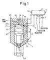
- Fig. 1 is a schematic view of a fuel injection control device according to the present invention.
- Reference numeral 1 designates a fuel injector arranged on each cylinder
- reference numeral 2 designates a pressurized fuel chamber.
- Each fuel injector 1 and the pressurized fuel chamber 2 are connected via each pipe 3.
- Each fuel injector 1 injects high-pressure fuel pressurized in the chamber 2 common to each cylinder, for example, to supply fuel directly into the cylinder of a diesel engine or a direct fuel injection type spark ignition engine.
- the fuel injector 1 can be used to inject fuel into, for example an intake port and not into a cylinder.
- a high-pressure pump (not shown) is connected to the pressurized fuel chamber 2 to maintain the desired high fuel pressure in the pressurized fuel chamber 2.
- the high-pressure pump is usually driven by the engine and, for example, pumps an amount of fuel consumed in fuel injections by two fuel injectors into the pressurized fuel chamber 2 at the end of the fuel injections.
- a pressure sensor 4 is arranged to detect a fuel pressure in the pressurized fuel chamber 2.
- Reference numeral 5 is a temperature sensor to detect a fuel temperature in the pressurized fuel chamber 2.
- Each fuel injector 1 comprises a valve body 11 for an injection hole, for example, which can slide in the axial direction, and the tip portion of the valve body 11 can open and shut the injection hole 12.
- the fuel pressure in the tip space 13 communicating with the injection hole 12 acts on the tip side of the valve body 11 and the fuel pressure in the base space 14 acts on the base side of the valve body 11.
- a high fuel pressure passage 15 is formed in the fuel injector 1.
- the high fuel pressure passage 15 communicates with the base space 14 via an orifice 16 and directly with the tip space 13.
- the pipe 3 communicating with the pressurized fuel chamber 2 is connected to the high fuel pressure passage 15 at the vicinity of the base space 14.
- a closing spring 17 is arranged to bias the valve body 11 in the closing direction.
- a control valve body chamber 19 in which a control valve body 18 is positioned is provided in the vicinity of the base space 14, and communicates with a fuel tank via a low fuel pressure passage 20.
- the control valve body chamber 19 is communicated with the base space 14 via a communicating passage 22 having an orifice 21.
- the control valve body 18 is controlled to open or shut the communicating passage 22 by an actuator (not shown).
- the fuel pressure in the base space 14 becomes the same high-fuel pressure as that in the high fuel passage 15 by the high pressure fuel supplied via the orifice 16 from the high fuel pressure passage 15.
- the area receiving the pressure in the opening direction (the area facing to the base space 14) and the area receiving the pressure in the closing direction (the area facing to the tip space 13) are (A1) shown by a chain line as a perspective view, and are equal each other.
- the fuel pressure in the tip space 13 is the same high fuel pressure as that in the high fuel pressure passage 15 and thus the pressing force acting on the valve body 11 for the injection hole in the closing direction by the fuel pressure in the base space 14 and the pressing force acting on the valve body 11 in the opening direction by the fuel pressure in the tip space 13 are equal and offset each other. Therefore, the valve body 11 is closed by the pressing force of the closing spring 17 in the closing direction.
- the area receiving the fuel pressure in the tip portion of the valve body 11, i.e., the area receiving the fuel pressure in the opening direction decreases from (A1 ) to a doughnut-like shape (A2) shown by a chain line as a perspective view.
- the area receiving the fuel pressure in the base portion of the valve body 11 in the opening direction is still (Al).
- the pressing force (P2) of the closing spring 17 in the closing direction also acts on the valve body 11 and thus the valve body 11 is certainly closed.
- the valve body 11 When the valve body 11 is opened, the area receiving the fuel pressure in the opening direction and the area receiving the fuel pressure in the closing direction become equal. Then, when the control valve body 18 shuts the communicating passage 22 and the fuel pressure in the base space 14 becomes equal to the high fuel pressure in the tip space 13, the valve body 11 is closed and the fuel injection is stopped. Thus, the control valve body 18 is opened or closed and the flowing out of the fuel in the base space 14 is controlled. Therefore, the valve body 11 for the injection hole is opened with the decrease of the fuel pressure in the base space 14 and is closed with the increase of the fuel pressure in the base space 14. Thus, the base space 14 functions as a control chamber.
- Fig. 2 is a time chart showing changes of opening or closing of the control valve body 18 and of the fuel pressure in the tip space 13 of the fuel injector.
- the fuel pressure (P) is an initial fuel pressure in the tip space 13 corresponding to the high fuel pressure in the pressurized fuel chamber 2.
- the control valve body 18 is opened by an opening order at the time (t0') and the fuel in the base space 14 starts to flow out to the low fuel pressure passage 20 via the control valve body chamber 19.
- the control valve body 18 is closed by a close command and the flowing out of the fuel in the base space 14 is stopped.
- the fuel pressure in the base space 14 of the fuel injector decreases.
- the high-pressure fuel is supplied to the base space 14 via the orifice 16 and thus the fuel pressure in the high fuel pressure passage 15 and the tip space 13 has decreased for a period between the time (t0) and the time (t1).
- a negative pressure wave is produced in the tip space 13 at the time (t1) and it propagates toward the pressurized fuel chamber 2.
- the chamber 2 as an open end reflects the negative pressure wave as a positive pressure wave and it propagates toward the fuel injector.
- the positive pressure wave reaches the top space 13
- the intensity thereof becomes slightly smaller due to damping but it makes the fuel pressure in the tip space 13 of the fuel injector increase at the time (t2) as shown by a dotted line.
- control valve body 18 is opened at the time (t2-) and is closed at the time ⁇ t3') such that, for the pilot fuel injection, the valve body 11 for the injection hole is opened at the time (t2) to start the fuel injection, and is closed at the time (t3) to finish the fuel injection, and thus a desired amount of fuel is injected.
- the positive pressure wave makes the fuel pressure in the tip space 13 that actually influences the fuel injection increase, and thus the high fuel injection rate can be realized and the fuel can be dispersed widely in the whole of the combustion chamber. Accordingly, when the combustion starts with the main fuel injection after the pilot fuel injection, the fuel can ignite in the whole of the combustion chamber.
- the fuel pressure in the tip space 13 actually drops according to the pilot fuel injection as shown by a solid line. Therefore, when the valve body 11 for the injection hole is closed at the time (t3) and the pilot fuel injection finishes, a negative pressure wave is produced in the tip space 13 and it propagates toward the pressurized fuel chamber 2.
- the chamber 2 as an open end, reflects the negative pressure wave as a positive pressure wave and it propagates toward the fuel injector.
- the positive pressure wave reaches the tip space 3 the intensity thereof becomes slightly smaller due to damping but it makes the fuel pressure in the tip space 13 of the fuel injector increase between the time (t4) and the time(t5) as shown by a solid line.
- the positive pressure wave propagates toward the pressurized fuel chamber 2 as it is.
- the chamber 2 as an open end, reflects the positive pressure wave as a negative pressure wave and it propagates toward the fuel injector.
- the negative pressure wave reaches the top space 13, the intensity thereof becomes slightly smaller due to damping but it makes the fuel pressure in the tip space 13 of the fuel injector decrease at the time (t6) as shown by a dotted line.
- control valve body 18 is opened at the time (t6') and is closed at the time (t7') such that, for the main fuel injection, the valve body 11 for the injection hole is opened at the time (t6) to start the fuel injection, and is closed at the time (t7) to finish the fuel injection, and thus a desired amount of fuel is injected.
- the negative pressure wave makes the fuel pressure in the tip space 13 that actually influences the fuel injection decrease, and thus the low fuel injection rate can be realized. Accordingly, it can be prevented that the large amount of fuel burns simultaneously with the start of the fuel injection and thus a large noise is not produced.
- the time (t2) at which the arrival positive pressure wave makes the fuel pressure in the tip space 13 of the fuel injector increase, and the time (t6) at which the arrival negative pressure wave makes the fuel pressure in the tip space 13 of the fuel injector decrease must be known.
- the time (t6) that is the starting time of the main fuel injection is decided on the basis of the piston position or the like. Accordingly, the time (t2), the time (t0), and the like are calculated on the basis of the time (t6).
- the period between the time (t1) and the time (t2), the period between the time (t3) and the time (t4), and the period between the time (t5) and the time (t6) are a period (T) in which the pressure wave leaves and returns between the tip space 13 and the pressurized fuel chamber 2.
- the period (T) can be calculated on the basis of the pressure propagation speed (V) in the fuel. Namely, the distance between the tip space 13 of the fuel injector 1 and the pressurized fuel chamber 2 is (L1+L2) as shown in Fig. 1, and thus the period (T) can be calculated on the basis of 2(L1+L2)/V.
- the pressure propagation speed changes in accordance with the temperature, the pressure, and the properties of fuel, and thus it is preferable that the pressure propagation speed is decided on the basis of them.
- the period between the time (t2) and the time (t3) is the pilot fuel injection period for which the valve body 11 for the injection hole has been opened.
- the period between the time (t4) at which the positive pressure wave produced by the negative pressure wave of the pilot fuel injection reaches the tip space 13, and the time (t5) at which the tip space 13 reflects the positive pressure wave is equal to the pilot fuel injection period.
- the time (t2) at which the pilot fuel injection starts can be calculated from the time (t6) at which the main fuel injection starts.
- the time (t1) at which the negative pressure wave is produced in the tip space 13 to produce the positive pressure wave for making the fuel pressure in the tip space 13 increase in the pilot fuel injection is the period (T) in which the pressure wave leaves and returns between the tip space 13 and the pressurized fuel chamber 2 before the time (t2) at which the pilot fuel injection starts.
- Delay periods such as the period from the time (t0-) at which the control valve body 18 is opened to the time (t0) at which the fuel pressure in the tip portion 13 actually starts to drop, the period from the time (t1') at which the control valve body 18 is closed to the time (t1) at which the negative pressure wave is actually produced in the tip portion 13, the period from the time (t2') at which the control valve body 18 is opened to the time (t2) at which the pilot fuel injection actually starts, the period from the time (t3') at which the control valve body 18 is closed to the time (t3) at which the pilot fuel injection actually finishes, the period from the time (t6') at which the control valve body 18 is opened to the time (t6) at which the main fuel injection actually starts, and the period from the time (t7') at which the control valve body 18 is closed to the time (t7) at which the main fuel injection actually finishes, are set on the basis of the fuel pressures in the tip portion 3 and in the pressurized fuel chamber 2.
- the pressure decreasing period (t0-t1) which produces the negative pressure wave in the tip portion 13 without the fuel injection, the pilot fuel injection period (t2-t3), and the pressure increasing period (t4-t5) in the tip portion 13 due to the reflection wave of the negative pressure wave produced by the pilot fuel injection are very short in comparison with the period (T) in which the pressure wave leaves and returns between the tip space 13 and the pressurized fuel chamber 2. Accordingly, these periods may be ignored to simplify the control of the control valve body 18.
- the pilot fuel injection may start on the basis that the positive pressure wave reaches the fuel injector the period (T) after the time (t0) at which the fuel pressure in the tip portion initially drops, and the main fuel injection may start on the basis that the negative pressure wave reaches the fuel injector the two times of the period (T) after the time at which the pilot fuel injection starts.
- the pilot fuel injection is carried out when the negative pressure wave that is produced to decrease the fuel pressure in the tip portion 13 without the fuel injection reaches the fuel injector as the positive pressure wave and thus the negative pressure wave produced without the fuel injection is utilized in the pilot fuel injection.
- the main fuel injection may be carried out when the negative pressure wave that is produced to decrease the fuel pressure in the tip portion 13 without the fuel injection reaches the fuel injector as the negative pressure wave and thus the negative pressure wave produced without the fuel injection may be utilized in the main fuel injection.
- pilot fuel injections when two pilot fuel injections are carried out, these pilot fuel injections are preferably carried out at the high fuel injection rate.
- the first pilot fuel injection is carried out as shown in Fig. 2 and therefore the negative pressure wave produced by the first pilot fuel injection is reflected as the positive pressure wave.
- the second pilot fuel injection may be carried out.
- the negative pressure wave is produced in the tip portion 13 by the second pilot fuel injection.
- the negative pressure wave leaves and returns two times between the fuel injector and the pressurized fuel chamber, the negative pressure wave reaches the tip portion 13 and the main fuel injection may be carried out at this time.
- the pressure wave always leaves and returns between the fuel injector and the pressurized fuel chamber. Accordingly, the time at which the pilot fuel injection starts, on the basis of the time at which the main fuel injection starts, is necessarily decided in accordance with the period in which the pressure wave leaves and returns, i.e., the length of the pipe.
- the pressure wave may leave and return odd times between the time (t1) at which the negative pressure wave is produced without the fuel injection and the time (t2) at which the pilot fuel injection starts.
- the time (t1) and the time (t2) can be changed.
- the more the odd times that the pressure wave leaves and returns increase, the more the pressure wave is damped.
- Fig. 3 shows another embodiment of a fuel injection control device.
- a variable orifice device 30 is arranged in each pipe between each fuel injector 1 and the pressurized fuel chamber 2.
- the variable orifice device 30 can make the inside diameter of the fuel passage therein very much larger or very much smaller than the inside diameter of the pipe 3.
- the variable orifice device 30, as a closed end reflects the pressure wave propagating from the fuel injector 1 to the pressurized fuel chamber 2 as the same pressure wave.
- the variable orifice device 30 as an open end reflects the pressure wave propagating from the fuel injector 1 to the pressurized fuel chamber 2 as the contrast pressure wave.
- variable orifice device 30 also can make the inside diameter of the fuel passage therein equal to the inside diameter of the pipe 3. At this time, the pressure wave propagating from the fuel injector 1 to the pressurized fuel chamber 2 passes merely through the variable orifice device 30.
- variable orifice device 30 can reflect the pressure wave as the same pressure wave or the opposite pressure wave toward the fuel injector. Further, the variable orifice device 30 can make the pressure wave pass therethrough and the pressurized fuel chamber can reflect the passed pressure wave as the opposite pressure wave toward the fuel injector. Accordingly, the period from the time at which the negative pressure wave is initially produced without the fuel injection to the time at which the pilot fuel injection is carried out, the period between the pilot fuel injection and the main fuel injection, the period between the two pilot fuel injections, and the like, can be changed in accordance with the engine operating condition.
- variable orifice device 30 when it is required that the period between the pilot fuel injection and the main fuel injection is made short, the variable orifice device 30, as an open end, may reflect the pressure wave, instead of the pressurized fuel chamber. Therefore, the pressure wave can return the fuel injector, in a short time, as a negative pressure wave. When it is required that this period is made shorter, the variable orifice device 30 as a close end may reflect the negative pressure wave produced by the pilot fuel injection as the negative pressure wave. When the negative pressure wave returns the fuel injector, the main fuel injection may be carried out. When two pilot fuel injections are carried out, the period between the two pilot fuel injections can be made short on the same basis.
- Fig. 4 shows a further embodiment of a fuel injection control device.
- each fuel injector 1 is connected to a first pressurized fuel chamber 2 having a high target fuel pressure and a second pressurized fuel chamber 2' having a target fuel pressure smaller than the high target fuel pressure and thus each fuel injector 1 can inject fuel at two fuel pressures.
- the first pressurized fuel chamber 2 is connected to the fuel injector 1 via a first pipe 3 and the second pressurized fuel chamber 2' is connected to the fuel injector 1 via a second pipe 3'.
- Reference numeral 40 designates a changeover valve by which one of the pressurized fuel chambers 2, 2' is connected to the fuel injector 1.
- the period from the time at which the negative pressure wave in the tip portion is produced without the fuel injection to the time at which the pilot fuel injection is carried out, the period between the pilot fuel injection and the main fuel injection, and the period between the two pilot fuel injections are not intended to change in accordance with the fuel injection pressure.
- the pipe length (L3) from the first pressurized fuel chamber 2 to the fuel injector 1 via the changeover valve 40 is made long and the pipe length (L4) from the second pressurized fuel chamber 2' to the fuel injector 1 via the changeover valve 40 is made short. Accordingly, when the fuel is injected at either fuel pressure, the pressure wave leaves and returns between the fuel injector and the corresponding pressurized fuel chamber in the same period.
- a fuel injection control device comprises a pressurized fuel chamber and a fuel injector connected with the pressurized fuel chamber via a pipe.
- the fuel injector carries out a pilot fuel injection and a main fuel injection, a part of the fuel is consumed from the fuel injector without the fuel injection to produce a negative pressure wave in the fuel injector such that a positive pressure wave reaches the fuel injector in the pilot fuel injection or a negative pressure wave reaches the fuel injector in the main fuel injection.
Landscapes
- Engineering & Computer Science (AREA)
- Chemical & Material Sciences (AREA)
- Combustion & Propulsion (AREA)
- Mechanical Engineering (AREA)
- General Engineering & Computer Science (AREA)
- Fuel-Injection Apparatus (AREA)
- Electrical Control Of Air Or Fuel Supplied To Internal-Combustion Engine (AREA)
Abstract
Description
Claims (4)
- A fuel injection control device, comprising a pressurized fuel chamber and a fuel injector connected with said pressurized fuel chamber via a pipe, wherein, when said fuel injector carries out a pilot fuel injection and a main fuel injection, a part of the fuel is consumed from said fuel injector without a fuel injection to produce a negative pressure wave in said fuel injector such that a positive pressure wave reaches said fuel injector during said pilot fuel injection or a negative pressure wave reaches said fuel injector during said main fuel injection.
- A fuel injection control device, according to claim 1, wherein when said negative pressure wave produced to consume said part of the fuel in said fuel injector leaves and returns once or odd times as the pressure wave between said fuel injector and said pressurized fuel chamber, and reaches said fuel injector as a positive pressure wave, said pilot fuel injection is carried out, and when a negative pressure wave produced by said pilot fuel injection leaves and returns twice or even times as the pressure wave between said fuel injector and said pressurized fuel chamber, and reaches said fuel injector as a negative pressure wave, said main fuel injection is carried out.
- A fuel injection control device according to claim 1, wherein a variable orifice device that can reflect said pressure wave propagating from said fuel injector to said pressurized fuel chamber as a negative pressure wave or a positive pressure wave, and that can make said pressure wave pass therethrough, is provided between said fuel injector and said pressurized fuel chamber, when said negative pressure wave produced to consume said part of the fuel in said fuel injector is reflected by said variable orifice device as said positive pressure wave, and said positive pressure wave reaches said fuel injector, said pilot fuel injection is carried out, and when a negative pressure wave produced by said pilot fuel injection is finally reflected by said variable orifice device or by said pressurized fuel chamber as said negative pressure wave, and said negative pressure wave reaches said fuel injector, said main fuel injection is carried out.
- A fuel injection control device according to claim 2, wherein the first pressurized fuel chamber having a high target fuel pressure and the second pressurized fuel chamber having a target fuel pressure smaller than said high target fuel pressure are provided, said pipe has changeover means to connect said fuel injector to either said first pressurized fuel chamber or said second pressurized fuel chamber, a path length between said fuel injector and said first pressurized fuel chamber via said pipe is made longer than that between said fuel injector and said second pressurized fuel chamber via said pipe, a period in which said pressure wave leaves and return one time between said fuel injector and said first pressurized fuel chamber when said fuel injector is connected to said first pressurized fuel chamber by said changeover means is made equal to a period in which said pressure wave leaves and return one time between said fuel injector and said second pressurized fuel chamber when said fuel injector is connected to said second pressurized fuel chamber by said changeover means, if said pilot fuel injection and said main fuel injection are carried out by using of either said first pressurized fuel chamber or said second pressurized fuel chamber, the period between said pilot fuel injection and said main fuel injection is constant.
Applications Claiming Priority (2)
| Application Number | Priority Date | Filing Date | Title |
|---|---|---|---|
| JP2002146408A JP3855846B2 (en) | 2002-05-21 | 2002-05-21 | Fuel injection control device for internal combustion engine |
| JP2002146408 | 2002-05-21 |
Publications (3)
| Publication Number | Publication Date |
|---|---|
| EP1365135A2 true EP1365135A2 (en) | 2003-11-26 |
| EP1365135A3 EP1365135A3 (en) | 2006-04-12 |
| EP1365135B1 EP1365135B1 (en) | 2009-02-11 |
Family
ID=29397792
Family Applications (1)
| Application Number | Title | Priority Date | Filing Date |
|---|---|---|---|
| EP03011424A Expired - Lifetime EP1365135B1 (en) | 2002-05-21 | 2003-05-20 | A fuel injection control device |
Country Status (3)
| Country | Link |
|---|---|
| EP (1) | EP1365135B1 (en) |
| JP (1) | JP3855846B2 (en) |
| DE (1) | DE60326101D1 (en) |
Cited By (4)
| Publication number | Priority date | Publication date | Assignee | Title |
|---|---|---|---|---|
| GB2402233A (en) * | 2003-05-30 | 2004-12-01 | Ford Global Tech Llc | A method for controlling pressure fluctuations in high pressure fuel injector supply lines |
| US7765995B2 (en) | 2007-08-31 | 2010-08-03 | Denso Corporation | Fuel injection device and fuel injection system |
| US8539935B2 (en) | 2007-08-31 | 2013-09-24 | Denso Corporation | Fuel injection device, fuel injection system, and method for determining malfunction of the same |
| WO2013189682A1 (en) * | 2012-06-22 | 2013-12-27 | Robert Bosch Gmbh | Method for operating a common rail injection system |
Families Citing this family (4)
| Publication number | Priority date | Publication date | Assignee | Title |
|---|---|---|---|---|
| JP4826540B2 (en) * | 2007-04-27 | 2011-11-30 | トヨタ自動車株式会社 | Fuel injection system for compression ignition internal combustion engine |
| JP5195842B2 (en) | 2010-08-18 | 2013-05-15 | 株式会社デンソー | Pressure reducing valve controller |
| JP6481597B2 (en) * | 2015-12-03 | 2019-03-13 | 株式会社デンソー | Fuel injection control device, fuel injection system, and fuel injection valve |
| JP2019519725A (en) * | 2016-05-11 | 2019-07-11 | ペーター フックス テクノロジー グループ アクチェンゲゼルシャフト | High pressure conduit |
Family Cites Families (5)
| Publication number | Priority date | Publication date | Assignee | Title |
|---|---|---|---|---|
| EP1064457B1 (en) * | 1998-03-16 | 2002-06-12 | Siemens Aktiengesellschaft | Method for determining the injection time in a direct injection internal combustion engine |
| DE19937148B4 (en) * | 1999-08-06 | 2012-12-27 | Robert Bosch Gmbh | Method for determining the fuel injection quantities |
| JP4588971B2 (en) * | 2000-07-18 | 2010-12-01 | ローベルト ボツシユ ゲゼルシヤフト ミツト ベシユレンクテル ハフツング | Method and apparatus for controlling an internal combustion engine |
| FR2833654B1 (en) * | 2001-12-17 | 2004-02-20 | Renault | INJECTOR CONTROL METHOD |
| JP3941761B2 (en) * | 2003-09-01 | 2007-07-04 | トヨタ自動車株式会社 | Fuel injection device for internal combustion engine |
-
2002
- 2002-05-21 JP JP2002146408A patent/JP3855846B2/en not_active Expired - Fee Related
-
2003
- 2003-05-20 DE DE60326101T patent/DE60326101D1/en not_active Expired - Lifetime
- 2003-05-20 EP EP03011424A patent/EP1365135B1/en not_active Expired - Lifetime
Cited By (5)
| Publication number | Priority date | Publication date | Assignee | Title |
|---|---|---|---|---|
| GB2402233A (en) * | 2003-05-30 | 2004-12-01 | Ford Global Tech Llc | A method for controlling pressure fluctuations in high pressure fuel injector supply lines |
| GB2402233B (en) * | 2003-05-30 | 2006-10-11 | Ford Global Tech Llc | Fuel injector supply |
| US7765995B2 (en) | 2007-08-31 | 2010-08-03 | Denso Corporation | Fuel injection device and fuel injection system |
| US8539935B2 (en) | 2007-08-31 | 2013-09-24 | Denso Corporation | Fuel injection device, fuel injection system, and method for determining malfunction of the same |
| WO2013189682A1 (en) * | 2012-06-22 | 2013-12-27 | Robert Bosch Gmbh | Method for operating a common rail injection system |
Also Published As
| Publication number | Publication date |
|---|---|
| JP2003343330A (en) | 2003-12-03 |
| EP1365135A3 (en) | 2006-04-12 |
| DE60326101D1 (en) | 2009-03-26 |
| JP3855846B2 (en) | 2006-12-13 |
| EP1365135B1 (en) | 2009-02-11 |
Similar Documents
| Publication | Publication Date | Title |
|---|---|---|
| US7040290B2 (en) | Common rail system | |
| US5072706A (en) | Fuel injection pump for internal combustion engines, in particular diesel engines | |
| US20100133361A1 (en) | Fuel injection valve for internal combustion engine | |
| JPS63147967A (en) | Fuel injection system | |
| JPH10505648A (en) | Fuel injection rate formation control system | |
| US11598300B2 (en) | Fuel system for reducing fuel targeting errors and engine operating method | |
| US6332447B1 (en) | Diesel engine | |
| US8881709B2 (en) | Fluid injector with back end rate shaping capability | |
| JP3775498B2 (en) | Accumulated fuel injection system | |
| EP1164283A2 (en) | A fuel injection valve | |
| EP1365135B1 (en) | A fuel injection control device | |
| JP3932688B2 (en) | Fuel injection device for internal combustion engine | |
| JP4061803B2 (en) | Accumulated fuel injection system | |
| ATE471450T1 (en) | INJECTOR | |
| JP3846362B2 (en) | Fuel injection control device for internal combustion engine | |
| JP3904121B2 (en) | Accumulated fuel injection valve | |
| JP4158541B2 (en) | Fuel injection device for internal combustion engine | |
| KR20060028699A (en) | Fuel injection system with reduced pressure pulsation in return rail | |
| JP4239332B2 (en) | Fuel injection device for internal combustion engine | |
| JP2020112159A (en) | Method of operating internal combustion engine, and control device | |
| US20090173316A1 (en) | Injection means for a combustion engine | |
| JP6528405B2 (en) | Fuel injection device for internal combustion engine | |
| JPS58165566A (en) | Fuel injection valve | |
| JP2001295717A (en) | Fuel injection valve | |
| JPS60162054A (en) | Fuel injection device for diesel engine |
Legal Events
| Date | Code | Title | Description |
|---|---|---|---|
| PUAI | Public reference made under article 153(3) epc to a published international application that has entered the european phase |
Free format text: ORIGINAL CODE: 0009012 |
|
| 17P | Request for examination filed |
Effective date: 20030520 |
|
| AK | Designated contracting states |
Kind code of ref document: A2 Designated state(s): AT BE BG CH CY CZ DE DK EE ES FI FR GB GR HU IE IT LI LU MC NL PT RO SE SI SK TR |
|
| AX | Request for extension of the european patent |
Extension state: AL LT LV MK |
|
| PUAL | Search report despatched |
Free format text: ORIGINAL CODE: 0009013 |
|
| AK | Designated contracting states |
Kind code of ref document: A3 Designated state(s): AT BE BG CH CY CZ DE DK EE ES FI FR GB GR HU IE IT LI LU MC NL PT RO SE SI SK TR |
|
| AX | Request for extension of the european patent |
Extension state: AL LT LV MK |
|
| 17Q | First examination report despatched |
Effective date: 20060713 |
|
| AKX | Designation fees paid |
Designated state(s): DE FR IT |
|
| GRAP | Despatch of communication of intention to grant a patent |
Free format text: ORIGINAL CODE: EPIDOSNIGR1 |
|
| GRAS | Grant fee paid |
Free format text: ORIGINAL CODE: EPIDOSNIGR3 |
|
| GRAA | (expected) grant |
Free format text: ORIGINAL CODE: 0009210 |
|
| AK | Designated contracting states |
Kind code of ref document: B1 Designated state(s): DE FR IT |
|
| REF | Corresponds to: |
Ref document number: 60326101 Country of ref document: DE Date of ref document: 20090326 Kind code of ref document: P |
|
| PLBE | No opposition filed within time limit |
Free format text: ORIGINAL CODE: 0009261 |
|
| STAA | Information on the status of an ep patent application or granted ep patent |
Free format text: STATUS: NO OPPOSITION FILED WITHIN TIME LIMIT |
|
| 26N | No opposition filed |
Effective date: 20091112 |
|
| PGFP | Annual fee paid to national office [announced via postgrant information from national office to epo] |
Ref country code: FR Payment date: 20100525 Year of fee payment: 8 |
|
| PGFP | Annual fee paid to national office [announced via postgrant information from national office to epo] |
Ref country code: DE Payment date: 20100512 Year of fee payment: 8 Ref country code: IT Payment date: 20100522 Year of fee payment: 8 |
|
| REG | Reference to a national code |
Ref country code: FR Ref legal event code: ST Effective date: 20120131 |
|
| PG25 | Lapsed in a contracting state [announced via postgrant information from national office to epo] |
Ref country code: IT Free format text: LAPSE BECAUSE OF NON-PAYMENT OF DUE FEES Effective date: 20110520 |
|
| REG | Reference to a national code |
Ref country code: DE Ref legal event code: R119 Ref document number: 60326101 Country of ref document: DE Effective date: 20111201 |
|
| PG25 | Lapsed in a contracting state [announced via postgrant information from national office to epo] |
Ref country code: FR Free format text: LAPSE BECAUSE OF NON-PAYMENT OF DUE FEES Effective date: 20110531 |
|
| PG25 | Lapsed in a contracting state [announced via postgrant information from national office to epo] |
Ref country code: DE Free format text: LAPSE BECAUSE OF NON-PAYMENT OF DUE FEES Effective date: 20111201 |