EP1365113A2 - Locking pin mechanism for a camshaft phaser - Google Patents
Locking pin mechanism for a camshaft phaser Download PDFInfo
- Publication number
- EP1365113A2 EP1365113A2 EP03076357A EP03076357A EP1365113A2 EP 1365113 A2 EP1365113 A2 EP 1365113A2 EP 03076357 A EP03076357 A EP 03076357A EP 03076357 A EP03076357 A EP 03076357A EP 1365113 A2 EP1365113 A2 EP 1365113A2
- Authority
- EP
- European Patent Office
- Prior art keywords
- phaser
- locking pin
- rotor
- bore
- accordance
- Prior art date
- Legal status (The legal status is an assumption and is not a legal conclusion. Google has not performed a legal analysis and makes no representation as to the accuracy of the status listed.)
- Withdrawn
Links
- RDYMFSUJUZBWLH-UHFFFAOYSA-N endosulfan Chemical compound C12COS(=O)OCC2C2(Cl)C(Cl)=C(Cl)C1(Cl)C2(Cl)Cl RDYMFSUJUZBWLH-UHFFFAOYSA-N 0.000 title claims abstract description 65
- 230000007246 mechanism Effects 0.000 title claims abstract description 30
- 238000002485 combustion reaction Methods 0.000 claims description 5
- 230000006835 compression Effects 0.000 claims description 3
- 238000007906 compression Methods 0.000 claims description 3
- 238000000034 method Methods 0.000 claims description 2
- 238000005553 drilling Methods 0.000 description 3
- 230000005355 Hall effect Effects 0.000 description 2
- 230000008901 benefit Effects 0.000 description 2
- 238000004891 communication Methods 0.000 description 2
- 238000012986 modification Methods 0.000 description 2
- 230000004048 modification Effects 0.000 description 2
- 241001136800 Anas acuta Species 0.000 description 1
- 230000008859 change Effects 0.000 description 1
- 238000006073 displacement reaction Methods 0.000 description 1
- 239000012530 fluid Substances 0.000 description 1
- 238000009434 installation Methods 0.000 description 1
- 238000003754 machining Methods 0.000 description 1
- 230000013011 mating Effects 0.000 description 1
- 238000005259 measurement Methods 0.000 description 1
- 239000002184 metal Substances 0.000 description 1
- 238000012544 monitoring process Methods 0.000 description 1
- 230000003287 optical effect Effects 0.000 description 1
- 230000004044 response Effects 0.000 description 1
- 230000035939 shock Effects 0.000 description 1
- 238000013022 venting Methods 0.000 description 1
Images



Classifications
-
- F—MECHANICAL ENGINEERING; LIGHTING; HEATING; WEAPONS; BLASTING
- F01—MACHINES OR ENGINES IN GENERAL; ENGINE PLANTS IN GENERAL; STEAM ENGINES
- F01L—CYCLICALLY OPERATING VALVES FOR MACHINES OR ENGINES
- F01L1/00—Valve-gear or valve arrangements, e.g. lift-valve gear
- F01L1/34—Valve-gear or valve arrangements, e.g. lift-valve gear characterised by the provision of means for changing the timing of the valves without changing the duration of opening and without affecting the magnitude of the valve lift
- F01L1/344—Valve-gear or valve arrangements, e.g. lift-valve gear characterised by the provision of means for changing the timing of the valves without changing the duration of opening and without affecting the magnitude of the valve lift changing the angular relationship between crankshaft and camshaft, e.g. using helicoidal gear
-
- F—MECHANICAL ENGINEERING; LIGHTING; HEATING; WEAPONS; BLASTING
- F01—MACHINES OR ENGINES IN GENERAL; ENGINE PLANTS IN GENERAL; STEAM ENGINES
- F01L—CYCLICALLY OPERATING VALVES FOR MACHINES OR ENGINES
- F01L1/00—Valve-gear or valve arrangements, e.g. lift-valve gear
- F01L1/02—Valve drive
- F01L1/022—Chain drive
-
- F—MECHANICAL ENGINEERING; LIGHTING; HEATING; WEAPONS; BLASTING
- F01—MACHINES OR ENGINES IN GENERAL; ENGINE PLANTS IN GENERAL; STEAM ENGINES
- F01L—CYCLICALLY OPERATING VALVES FOR MACHINES OR ENGINES
- F01L1/00—Valve-gear or valve arrangements, e.g. lift-valve gear
- F01L1/34—Valve-gear or valve arrangements, e.g. lift-valve gear characterised by the provision of means for changing the timing of the valves without changing the duration of opening and without affecting the magnitude of the valve lift
-
- F—MECHANICAL ENGINEERING; LIGHTING; HEATING; WEAPONS; BLASTING
- F01—MACHINES OR ENGINES IN GENERAL; ENGINE PLANTS IN GENERAL; STEAM ENGINES
- F01L—CYCLICALLY OPERATING VALVES FOR MACHINES OR ENGINES
- F01L1/00—Valve-gear or valve arrangements, e.g. lift-valve gear
- F01L1/34—Valve-gear or valve arrangements, e.g. lift-valve gear characterised by the provision of means for changing the timing of the valves without changing the duration of opening and without affecting the magnitude of the valve lift
- F01L1/344—Valve-gear or valve arrangements, e.g. lift-valve gear characterised by the provision of means for changing the timing of the valves without changing the duration of opening and without affecting the magnitude of the valve lift changing the angular relationship between crankshaft and camshaft, e.g. using helicoidal gear
- F01L1/3442—Valve-gear or valve arrangements, e.g. lift-valve gear characterised by the provision of means for changing the timing of the valves without changing the duration of opening and without affecting the magnitude of the valve lift changing the angular relationship between crankshaft and camshaft, e.g. using helicoidal gear using hydraulic chambers with variable volume to transmit the rotating force
-
- F—MECHANICAL ENGINEERING; LIGHTING; HEATING; WEAPONS; BLASTING
- F01—MACHINES OR ENGINES IN GENERAL; ENGINE PLANTS IN GENERAL; STEAM ENGINES
- F01L—CYCLICALLY OPERATING VALVES FOR MACHINES OR ENGINES
- F01L1/00—Valve-gear or valve arrangements, e.g. lift-valve gear
- F01L1/02—Valve drive
- F01L1/024—Belt drive
-
- F—MECHANICAL ENGINEERING; LIGHTING; HEATING; WEAPONS; BLASTING
- F01—MACHINES OR ENGINES IN GENERAL; ENGINE PLANTS IN GENERAL; STEAM ENGINES
- F01L—CYCLICALLY OPERATING VALVES FOR MACHINES OR ENGINES
- F01L1/00—Valve-gear or valve arrangements, e.g. lift-valve gear
- F01L1/34—Valve-gear or valve arrangements, e.g. lift-valve gear characterised by the provision of means for changing the timing of the valves without changing the duration of opening and without affecting the magnitude of the valve lift
- F01L1/344—Valve-gear or valve arrangements, e.g. lift-valve gear characterised by the provision of means for changing the timing of the valves without changing the duration of opening and without affecting the magnitude of the valve lift changing the angular relationship between crankshaft and camshaft, e.g. using helicoidal gear
- F01L1/3442—Valve-gear or valve arrangements, e.g. lift-valve gear characterised by the provision of means for changing the timing of the valves without changing the duration of opening and without affecting the magnitude of the valve lift changing the angular relationship between crankshaft and camshaft, e.g. using helicoidal gear using hydraulic chambers with variable volume to transmit the rotating force
- F01L2001/34423—Details relating to the hydraulic feeding circuit
- F01L2001/34426—Oil control valves
-
- F—MECHANICAL ENGINEERING; LIGHTING; HEATING; WEAPONS; BLASTING
- F01—MACHINES OR ENGINES IN GENERAL; ENGINE PLANTS IN GENERAL; STEAM ENGINES
- F01L—CYCLICALLY OPERATING VALVES FOR MACHINES OR ENGINES
- F01L1/00—Valve-gear or valve arrangements, e.g. lift-valve gear
- F01L1/34—Valve-gear or valve arrangements, e.g. lift-valve gear characterised by the provision of means for changing the timing of the valves without changing the duration of opening and without affecting the magnitude of the valve lift
- F01L1/344—Valve-gear or valve arrangements, e.g. lift-valve gear characterised by the provision of means for changing the timing of the valves without changing the duration of opening and without affecting the magnitude of the valve lift changing the angular relationship between crankshaft and camshaft, e.g. using helicoidal gear
- F01L1/3442—Valve-gear or valve arrangements, e.g. lift-valve gear characterised by the provision of means for changing the timing of the valves without changing the duration of opening and without affecting the magnitude of the valve lift changing the angular relationship between crankshaft and camshaft, e.g. using helicoidal gear using hydraulic chambers with variable volume to transmit the rotating force
- F01L2001/34423—Details relating to the hydraulic feeding circuit
- F01L2001/34426—Oil control valves
- F01L2001/3443—Solenoid driven oil control valves
-
- F—MECHANICAL ENGINEERING; LIGHTING; HEATING; WEAPONS; BLASTING
- F01—MACHINES OR ENGINES IN GENERAL; ENGINE PLANTS IN GENERAL; STEAM ENGINES
- F01L—CYCLICALLY OPERATING VALVES FOR MACHINES OR ENGINES
- F01L1/00—Valve-gear or valve arrangements, e.g. lift-valve gear
- F01L1/34—Valve-gear or valve arrangements, e.g. lift-valve gear characterised by the provision of means for changing the timing of the valves without changing the duration of opening and without affecting the magnitude of the valve lift
- F01L1/344—Valve-gear or valve arrangements, e.g. lift-valve gear characterised by the provision of means for changing the timing of the valves without changing the duration of opening and without affecting the magnitude of the valve lift changing the angular relationship between crankshaft and camshaft, e.g. using helicoidal gear
- F01L1/3442—Valve-gear or valve arrangements, e.g. lift-valve gear characterised by the provision of means for changing the timing of the valves without changing the duration of opening and without affecting the magnitude of the valve lift changing the angular relationship between crankshaft and camshaft, e.g. using helicoidal gear using hydraulic chambers with variable volume to transmit the rotating force
- F01L2001/34423—Details relating to the hydraulic feeding circuit
- F01L2001/34426—Oil control valves
- F01L2001/34433—Location oil control valves
-
- F—MECHANICAL ENGINEERING; LIGHTING; HEATING; WEAPONS; BLASTING
- F01—MACHINES OR ENGINES IN GENERAL; ENGINE PLANTS IN GENERAL; STEAM ENGINES
- F01L—CYCLICALLY OPERATING VALVES FOR MACHINES OR ENGINES
- F01L1/00—Valve-gear or valve arrangements, e.g. lift-valve gear
- F01L1/34—Valve-gear or valve arrangements, e.g. lift-valve gear characterised by the provision of means for changing the timing of the valves without changing the duration of opening and without affecting the magnitude of the valve lift
- F01L1/344—Valve-gear or valve arrangements, e.g. lift-valve gear characterised by the provision of means for changing the timing of the valves without changing the duration of opening and without affecting the magnitude of the valve lift changing the angular relationship between crankshaft and camshaft, e.g. using helicoidal gear
- F01L1/3442—Valve-gear or valve arrangements, e.g. lift-valve gear characterised by the provision of means for changing the timing of the valves without changing the duration of opening and without affecting the magnitude of the valve lift changing the angular relationship between crankshaft and camshaft, e.g. using helicoidal gear using hydraulic chambers with variable volume to transmit the rotating force
- F01L2001/3445—Details relating to the hydraulic means for changing the angular relationship
- F01L2001/34453—Locking means between driving and driven members
- F01L2001/34469—Lock movement parallel to camshaft axis
-
- F—MECHANICAL ENGINEERING; LIGHTING; HEATING; WEAPONS; BLASTING
- F01—MACHINES OR ENGINES IN GENERAL; ENGINE PLANTS IN GENERAL; STEAM ENGINES
- F01L—CYCLICALLY OPERATING VALVES FOR MACHINES OR ENGINES
- F01L1/00—Valve-gear or valve arrangements, e.g. lift-valve gear
- F01L1/34—Valve-gear or valve arrangements, e.g. lift-valve gear characterised by the provision of means for changing the timing of the valves without changing the duration of opening and without affecting the magnitude of the valve lift
- F01L1/344—Valve-gear or valve arrangements, e.g. lift-valve gear characterised by the provision of means for changing the timing of the valves without changing the duration of opening and without affecting the magnitude of the valve lift changing the angular relationship between crankshaft and camshaft, e.g. using helicoidal gear
- F01L1/3442—Valve-gear or valve arrangements, e.g. lift-valve gear characterised by the provision of means for changing the timing of the valves without changing the duration of opening and without affecting the magnitude of the valve lift changing the angular relationship between crankshaft and camshaft, e.g. using helicoidal gear using hydraulic chambers with variable volume to transmit the rotating force
- F01L2001/3445—Details relating to the hydraulic means for changing the angular relationship
- F01L2001/34479—Sealing of phaser devices
-
- F—MECHANICAL ENGINEERING; LIGHTING; HEATING; WEAPONS; BLASTING
- F01—MACHINES OR ENGINES IN GENERAL; ENGINE PLANTS IN GENERAL; STEAM ENGINES
- F01L—CYCLICALLY OPERATING VALVES FOR MACHINES OR ENGINES
- F01L1/00—Valve-gear or valve arrangements, e.g. lift-valve gear
- F01L1/34—Valve-gear or valve arrangements, e.g. lift-valve gear characterised by the provision of means for changing the timing of the valves without changing the duration of opening and without affecting the magnitude of the valve lift
- F01L1/344—Valve-gear or valve arrangements, e.g. lift-valve gear characterised by the provision of means for changing the timing of the valves without changing the duration of opening and without affecting the magnitude of the valve lift changing the angular relationship between crankshaft and camshaft, e.g. using helicoidal gear
- F01L1/3442—Valve-gear or valve arrangements, e.g. lift-valve gear characterised by the provision of means for changing the timing of the valves without changing the duration of opening and without affecting the magnitude of the valve lift changing the angular relationship between crankshaft and camshaft, e.g. using helicoidal gear using hydraulic chambers with variable volume to transmit the rotating force
- F01L2001/3445—Details relating to the hydraulic means for changing the angular relationship
- F01L2001/34483—Phaser return springs
-
- F—MECHANICAL ENGINEERING; LIGHTING; HEATING; WEAPONS; BLASTING
- F01—MACHINES OR ENGINES IN GENERAL; ENGINE PLANTS IN GENERAL; STEAM ENGINES
- F01L—CYCLICALLY OPERATING VALVES FOR MACHINES OR ENGINES
- F01L2800/00—Methods of operation using a variable valve timing mechanism
- F01L2800/01—Starting
-
- Y—GENERAL TAGGING OF NEW TECHNOLOGICAL DEVELOPMENTS; GENERAL TAGGING OF CROSS-SECTIONAL TECHNOLOGIES SPANNING OVER SEVERAL SECTIONS OF THE IPC; TECHNICAL SUBJECTS COVERED BY FORMER USPC CROSS-REFERENCE ART COLLECTIONS [XRACs] AND DIGESTS
- Y10—TECHNICAL SUBJECTS COVERED BY FORMER USPC
- Y10T—TECHNICAL SUBJECTS COVERED BY FORMER US CLASSIFICATION
- Y10T29/00—Metal working
- Y10T29/49—Method of mechanical manufacture
- Y10T29/49316—Impeller making
- Y10T29/4932—Turbomachine making
- Y10T29/49325—Shaping integrally bladed rotor
Definitions
- the present invention relates to a camshaft phaser for controlling the phase relationship between the crankshaft and a camshaft of an internal combustion engine; more particularly, to a vane-type phaser having a locking mechanism for selectively locking the rotor to the stator; and most particularly, to a locking mechanism for a vane-type phaser wherein a locking pin extends beyond the rotor chamber such that the pin may be manually withdrawn from locking engagement by an operator during mounting of the phaser to an engine to avoid torque damage to the locking pin mechanism.
- Camshaft phasers for internal combustion engines are well known.
- a camshaft phaser is disposed on the front of an engine and includes an oil control valve for controlling oil flow into and out of the phaser.
- the valve receives pressurized oil from an oil gallery in the engine block and selectively distributes oil to timing advance and retard chambers within the phaser to controllably vary the phase relationship between the engine's camshaft and crankshaft.
- the chambers are formed between inwardly-extending lobes of a generally cylindrical stator and outwardly-extending vanes of a rotor concentrically disposed within the stator.
- a prior art phaser may include a locking pin mechanism in a rotor vane.
- the mechanism typically includes a sleeve disposed in a bore in the vane and a spring-biased locking pin disposed in a well in the sleeve.
- the pin is biased to lock into a corresponding well in the sprocket to which the stator is mounted whenever the pin and sprocket well are rotationally aligned.
- the sprocket well communicates hydraulically with an oil pressure source to automatically force the pin from the sprocket well when certain engine operating conditions are met.
- the locking bolt bears on the rotor and hence can exert torque on the rotor as the bolt is being tightened. If the pin is engaged at that time, the pin may be damaged by torque from the rotor. In the prior art, it is generally not possible to ensure that the pin is not engaged as the bolt is tightened.
- Another problem encountered in the prior art is the inability to easily confirm the position of the locking pin relative to the sprocket well when the engine is operating.
- a locking pin mechanism in accordance with the invention is disposed in a bore in rotor vane for controllably engaging a well in the camshaft sprocket to rotationally lock the rotor and stator together.
- the mechanism comprises a lock pin sleeve disposed in the bore and extending from the vane through an arcuate slot in the inner cover plate.
- the sleeve terminates in an enlarged head outside the inner cover plate.
- the slot includes a portion wide enough to permit passage of the head through the slot during assembly of the phaser.
- the slot extends through a central arc at least equal to the actuation arc of the rotor within the stator, preferably about 30°.
- a slidable lock pin Disposed within the sleeve is a slidable lock pin having a locking head for engaging the sprocket well and a tail portion extending through the sleeve head.
- a compression spring within the sleeve urges the pin into lock relationship with the sprocket well whenever they are rotationally aligned.
- a groove in the sprocket connects the well with an oil source in the assembled phaser such that oil pressure overcomes the spring to retract the pin, unlocking the rotor from the stator.
- the tail portion of the lock pin extends beyond the cover plate and the sleeve head, permitting the lock pin to be manually retracted by an operator while the phaser is being installed or removed from the engine, thus preventing damage from high torque exerted via the phaser attachment bolt in bolting the phaser to or removal from the engine.
- a sensing device such as a Hall Effect sensor, placed proximate the tail portion of the locking pin, can be used to detect the position of the tail portion, and therefore the relative position of the locking head and the sprocket well while the engine is running.
- Phasers in accordance with the present invention meet this requirement and may be of either the spline type or vane type, as will be obvious to one of ordinary skill in the camshaft phaser art.
- a vane-type phaser is employed in the example below.
- the only engine change required is a modified front camshaft bearing, ported to provide oil to the phaser from the engine gallery supplying the camshaft and extended to provide a bearing surface for a new camshaft sprocket or pulley which previously was bolted directly to the camshaft but now is coupled to the camshaft via the phaser.
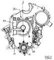
- a partially-assembled internal combustion engine shown generally as item 10, includes a crankshaft 12 disposed conventionally on block 14.
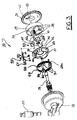
- a vane-type camshaft phaser 16 disposed on the front of engine 10 includes an outer cover 18 supporting and cooperating with an oil control valve 20 for controlling oil flow into and out of the phaser.
- Valve 20 receives pressurized oil from an oil gallery 22 in the engine block, as described below, and selectively distributes oil to timing advance and retard chambers within phaser 16, also as described below, to controllably vary the phase relationship between the engine's camshaft 24 and crankshaft 12 as is known in the prior art.
- Camshaft 24 is supported in a camshaft bearing 26 and is hollow at the outer end and threaded conventionally for receiving a phaser attachment bolt 28.
- Bearing 26 is modified from standard to extend forward of the end of camshaft 24 for rotatably supporting on an outer surface 27 thereof a drive means 30, such as, for example, a camshaft pulley or sprocket connected in known fashion via a timing belt or chain (not shown) to a smaller pulley or sprocket (not shown) mounted on the outer end of crankshaft 12.
- the two sprockets and timing chain are enclosed by a timing chain cover 32 mounted to engine block 14.
- Phaser 16 includes a stator 34 fixedly mounted to sprocket 30 for rotation therewith and an inner cover plate 36 conventionally attached to stator 34 and sprocket 30 via shouldered bolts 31 to define a rotor chamber 35.
- Stator 34 is formed having a plurality of spaced-apart inwardly-extending lobes 38.
- a rotor 40 having a hub 41 and a plurality of outwardly-extending vanes 42 interspersed between lobes 38 to form a plurality of opposing advance and retard chambers 44,46 therebetween. This arrangement is well known in the prior art of vane-type camshaft phasers and need not be further elaborated here.
- the preferred embodiment comprises three stator lobes and three rotor vanes.
- the lobes are arranged asymmetrically about axis 49 as shown in FIG. 5, permitting use of a vane 42a extending over a much larger internal angle 43 than the other two vanes 42. Vane 42a is thus able to accommodate a locking pin mechanism 45 as described more fully below.
- a first surface 48 of large vane 42a engages a lobe surface 50 at one extreme rotor rotation, as shown in FIG. 5, and a second surface 52 of large vane 42a engages a lobe surface 54 at the opposite extreme of rotation. Either or both surfaces 48,52 may be equipped with hardened wear pads 56.
- the wide angle vane 42a is stronger than the other two narrower vanes 42 and thus is better able to sustain the shock of impact when a vane strikes a lobe in an uncontrolled event such as at engine start-up.
- the rotor displacement angle preferably about 30° as shown in FIG. 5, may be limited and calibrated by secondary machining operations on the stator lobe and/or rotor vane contact surfaces.
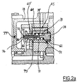
- locking pin mechanism 45 is disposed in a bore 60 in rotor vane 42a for controllably engaging a well 62 in sprocket 30 as desired to rotationally lock the rotor and stator together.
- Mechanism 45 comprises a lock pin sleeve 64 disposed in bore 60 and extending from vane 42a through an arcuate slot 66 in inner cover plate 36.
- sleeve 64 may terminate in an enlarged head 67 for retaining an external bias spring 68, as is described more fully below.
- slot 66 includes a portion 70 wide enough to permit passage of head 67 through the slot during assembly of the phaser. Slot 66 extends through a central arc at least equal to the actuation arc of the rotor within the stator, preferably about 30° as noted above. Vane 42a is of sufficient angular width such that the advance and retard chambers adjacent thereto are not exposed to slot 66 even at the extremes of rotor rotation.
- Lock pin 72 Slidingly disposed within an axial bore 71 in sleeve 64 is a lock pin 72 having a locking head portion 74 for engaging well 62 and a tail portion 76 extending through sleeve head 67.
- Lock pin 72 is single-acting within bore 71.
- a compression spring 78 within bore 71 urges pin 72 into lock relationship with well 62 whenever they are rotationally aligned.
- a groove 80 in sprocket 30 (FIG. 3) connects well 62 with a retard chamber 46 in the assembled phaser such that oil pressure applied to the retard chambers overcomes spring 78 to retract pin 72 into bore 71, unlocking the rotor from the stator.
- Body 73 of locking pin 72 includes longitudinal pressure balance passage 75 extending from tail portion 76 proximate cavity 81 surrounding locking pin mechanism 45, to proximity with a midpoint of pin 72.
- Radial connector bore 77 is in fluid communication with balance passage 75 and, in use, with sleeve axial bore 71, and the pressures in bore 71 and cavity 81 kept relatively balanced. Thus, oil trapped in axial bore 71 may be vented away from the axial bore.
- venting of axial bore 71 may be accomplished via a longitudinal balance groove 65 formed in sleeve 64.
- balance passage 75' shown as dotted lines in FIG. 2a
- connecting bore 71 with locking pin well 62 may be formed in head 74.
- Passage 75' serves to keep relatively balanced the pressures in bore 71 and well 62. Since the surface area of head 74 disposed in pin well 62 is greater than the surface area of the opposite surface of head 74 exposed in bore 71, oil pressure received from groove 80 (FIG. 3) will overcome spring 78 to retract pin 72 from well 62.
- tail portion 76 extends beyond cover plate 36 and head 67 (FIG. 4). This feature permits the lock pin to be manually retracted by an operator by grasping tail portion 76 while the phaser is being installed or removed from the engine, thus preventing damage from high torque exerted via cam attachment bolt 28 in bolting the phaser to the engine.
- a further advantage of the present locking mechanism is that by placing a sensing device such as, for example, a Hall Effect sensor - model number A3515LUA, made by Allegro Microsystems of Worcester, Mass. - proximate point 79 of outer cover 18, and by securing a permanent magnet proximate end 81 of pin tail portion 76, the magnetic field produced by the magnet can be measured.
- the relative position of locking head 74 and sprocket well 62 can be determined. This feature permits accurate monitoring and control of pin engagement/disengagement even when the engine is running. It is understood that other means of sensing the axial position of the locking pin in accordance with the invention may be used including, for example, by optical, sonic and inductance measurements.
- multiple-turn torsion bias spring 68 is disposed on the outer surface 37 of cover plate 36.
- a first tang 84 is engaged with a mandrel end 86 of a shouldered bolt 31, and a second tang 88 is engaged with head 67 of locking pin assembly 45.
- counterbore 82 proximate head 67 provides additional radial clearance between sleeve 64 and tail portion 76 of pin 72 so that forces placed on the sleeve by the torsion spring do not bind locking pin 72 during operation.
- Spring 68 is pre-stressed during phaser assembly such that the locking pin assembly, and hence rotor 40, is biased at its rest state to the fully retarded position shown in FIG. 5.
- Prior art phasers are known to employ a bias spring within the rotor chamber, but assembly of such an arrangement is difficult and prone to error.
- the external spring in accordance with the invention is easy to install, and correct installation is easily verified visually.
- phaser attachment bolt 28 serves the added purpose of providing passages for oil to flow from engine gallery 22 via bearing 26 to oil control valve 20 and from control valve 20 to advance and retard chambers 44,46.
- Bolt 28 has a bolt body 29 having a threaded portion 90 for engaging threaded end 91 of camshaft 24 as described above and a necked portion 92 cooperative with bore 94 in bearing 26 to form a first intermediate oil reservoir 98 in communication with gallery 22 via a passage (not shown) through bearing 26.
- a first longitudinal passage 100 in bolt 28 is formed as by drilling from bolt outer end 102 and extends internally to proximity with necked portion 92.
- An opening 104 connects passage 100 with reservoir 98. Oil is thus admitted via elements 104,100,102 to a second intermediate reservoir 106 formed between outer cover 18 and bolt outer end 102 from whence oil is supplied to control valve 20 via a passage (not shown) formed in outer cover 18.
- a check valve is disposed in the oil supply passage leading to the oil control valve to enhance the overall phaser system stiffness and response rate.
- Second and third longitudinal passages 108,110 in bolt 28 are formed as by drilling from outer end 102, then are plugged as by a press-fit ball 112 or other means to prevent entrance of oil from second intermediate reservoir 106.
- the three passages preferably are angularly disposed symmetrically about bolt and phaser axis 49 as shown in FIG. 8.
- Passages 108,110 are each drilled to a predetermined depth proximate to respective inner annular oil supply grooves 114,116 formed in the surface of bolt 28 for mating with an advance or retard oil channel (not shown) in the phaser rotor; then, each passage is opened to its respective annular oil supply groove preferably by removal of an arcuate bolt section 118, as shown in FIGS. 9 through 11. Further, outer annular oil supply grooves mate with control passages (not shown) in the cam cover 18. Each longitudinal passage 108,110 is opened to its respective outer annular oil supply groove 120,122 by drilling radial connecting bores 124,126, respectively.
- Lands 128,130,132 prevent leakage from inner grooves 114,116 by being machined to have a close fit within the rotor bore. Because in operation of the phaser the bolt turns with the rotor, no special seals are required. However, because the bolt rotates within cover 18, special seals are necessary for outer grooves 120,122.
- outer lands 134,136,138 each comprise twin lands separated by a narrow annular groove 140, each groove being provided with a metal seal ring 142 which is compressed radially into the cover bore 146 and thus is fixed with the cover and does not turn with the bolt.
- Bolt 28 is further provided with means for installing the bolt into the camshaft, preferably a wrenching feature.
- a hexagonal socket (not shown) may be formed in end surface 102 or preferably an external hexagonal feature 150 is formed into the middle region of bolt 28, which feature may be easily wrenched during phaser assembly by an appropriately deep socket wrench.
- phaser when the phaser is fully assembled and installed onto an engine, oil is provided from oil gallery 22 to control valve 20 via first passage 100 and from valve 20 to advance and retard chambers in the phaser via second and third passages 108,110. No modification is required of the engine block or camshaft in order to fit the present phaser to an engine.
Landscapes
- Engineering & Computer Science (AREA)
- Mechanical Engineering (AREA)
- General Engineering & Computer Science (AREA)
- Valve Device For Special Equipments (AREA)
- Valve-Gear Or Valve Arrangements (AREA)
- Lubrication Of Internal Combustion Engines (AREA)
Abstract
Description
Claims (11)
- A locking pin mechanism (45) for a vane-type camshaft phaser (16) having a rotor (40) disposed within a rotor chamber (35) formed by a stator (34), a drive means (30), and a cover plate (36), comprising:a) a first bore (60) in said rotor; andb) a locking pin (72) slidingly disposed in said first bore and having a tail portion (76) extending beyond said first bore (60) and said rotor chamber (35) through an opening (66) in said cover plate (36).
- A mechanism (45) in accordance with Claim 1 wherein said drive means is a sprocket.
- A mechanism (45) in accordance with Claim 1 wherein said drive means includes locking pin receiving means (62) and wherein said locking pin includes (72) a head portion (74) for entering said receiving means to lock said rotor (40) rotationally to said stator (34), said stator being fixed to said drive means.
- A mechanism (45) in accordance with Claim 3 wherein said locking pin (72) extending from said first bore (60) may be manually grasped and retracted from said locking pin receiving means (62).
- A mechanism (45) in accordance with Claim 1 further comprising a compression spring (78) disposed within said first bore (60) for urging said locking pin (72) toward said drive means (30).
- A mechanism (45) in accordance with Claim 1 wherein said opening (66) is an arcuate slot formed in said cover plate (36).
- A mechanism (45) in accordance with Claim 6 wherein said arcuate slot (66) subtends a central angle equal to the maximum rotational angle of said rotor within said stator.
- A mechanism (45) in accordance with Claim 1 wherein said locking pin (72) further includes a balance passage (75,77,75').
- A mechanism (45) in accordance with Claim 1 wherein said first bore (60) further includes a balance groove (65).
- A camshaft phaser (16) for an internal combustion engine (10), the phaser having a rotor (40) disposed within a rotor chamber (35) formed by a stator (34), a drive means (30), and a cover plate (36), the phaser comprising a locking pin mechanism (45)includinga first bore (50) in said rotor, anda locking pin ((72) slidingly disposed in said first bore (50) and having a tail portion (76) extending beyond said first bore (50) and said rotor chamber (35) through an opening (66) in said cover plate (36).
- A method of measuring the position of a cam phaser (16) locking pin (72) having a tail portion (76) extending from the cam phaser comprising the steps of:affixing a sensing means for sensing the proximate axial position of said tail portion; andmeasuring an output of the sensing means.
Applications Claiming Priority (2)
| Application Number | Priority Date | Filing Date | Title |
|---|---|---|---|
| US38223702P | 2002-05-21 | 2002-05-21 | |
| US382237P | 2002-05-21 |
Publications (2)
| Publication Number | Publication Date |
|---|---|
| EP1365113A2 true EP1365113A2 (en) | 2003-11-26 |
| EP1365113A3 EP1365113A3 (en) | 2007-12-26 |
Family
ID=29401635
Family Applications (3)
| Application Number | Title | Priority Date | Filing Date |
|---|---|---|---|
| EP03076355A Withdrawn EP1365111A3 (en) | 2002-05-21 | 2003-05-07 | Retention bolt for a cam phaser |
| EP03076358A Withdrawn EP1365114A3 (en) | 2002-05-21 | 2003-05-07 | Camshaft phaser with asymmetric vane rotor |
| EP03076357A Withdrawn EP1365113A3 (en) | 2002-05-21 | 2003-05-07 | Locking pin mechanism for a camshaft phaser |
Family Applications Before (2)
| Application Number | Title | Priority Date | Filing Date |
|---|---|---|---|
| EP03076355A Withdrawn EP1365111A3 (en) | 2002-05-21 | 2003-05-07 | Retention bolt for a cam phaser |
| EP03076358A Withdrawn EP1365114A3 (en) | 2002-05-21 | 2003-05-07 | Camshaft phaser with asymmetric vane rotor |
Country Status (2)
| Country | Link |
|---|---|
| US (4) | US6722330B2 (en) |
| EP (3) | EP1365111A3 (en) |
Cited By (3)
| Publication number | Priority date | Publication date | Assignee | Title |
|---|---|---|---|---|
| CN108223040A (en) * | 2016-12-14 | 2018-06-29 | 现代自动车株式会社 | Continuous variable valve opens duration device and the engine with the device |
| CN109386335A (en) * | 2017-08-02 | 2019-02-26 | 福特全球技术公司 | System and method for the variable cam timing phase control equipment with isolator |
| CN115213675A (en) * | 2022-08-16 | 2022-10-21 | 苏州高腾智能装备有限公司 | Adjusting method of lock pin clearance adjusting mechanism of camshaft phaser |
Families Citing this family (31)
| Publication number | Priority date | Publication date | Assignee | Title |
|---|---|---|---|---|
| US6722330B2 (en) * | 2002-05-21 | 2004-04-20 | Delphi Technologies, Inc. | Retention bolt for a cam phaser |
| US6817095B2 (en) * | 2002-06-11 | 2004-11-16 | Delphi Technologies, Inc. | Method for assembling a vane-type cam phaser |
| GB2401150A (en) * | 2003-04-29 | 2004-11-03 | Mechadyne Plc | I.c. engine camshaft oil supply arrangement |
| JP2004346806A (en) * | 2003-05-21 | 2004-12-09 | Mitsubishi Electric Corp | Valve timing adjustment system |
| DE102005007942B4 (en) * | 2004-02-27 | 2007-10-04 | Hydraulik-Ring Gmbh | Camshaft adjusting device for internal combustion engines of motor vehicles |
| US6948467B2 (en) * | 2004-02-27 | 2005-09-27 | Delphi Technologies, Inc. | Locking pin mechanism for a vane-type cam phaser |
| ATE356280T1 (en) | 2004-02-27 | 2007-03-15 | Hydraulik Ring Gmbh | CAMSHAFT ADJUSTMENT DEVICE FOR INTERNAL VEHICLE ENGINES |
| US7455075B2 (en) * | 2004-06-14 | 2008-11-25 | Minebea Co., Ltd. | Servo valve with miniature embedded force motor with stiffened armature |
| US20070056538A1 (en) * | 2005-09-13 | 2007-03-15 | Borgwarner Inc. | Electronic lock for VCT phaser |
| DE102006002993A1 (en) * | 2006-01-21 | 2007-08-09 | Schaeffler Kg | Camshaft adjuster for an internal combustion engine |
| DE102008001078A1 (en) * | 2008-04-09 | 2009-10-15 | Robert Bosch Gmbh | Device for changing the camshaft phase position |
| US8215274B2 (en) * | 2008-06-18 | 2012-07-10 | GM Global Technology Operations LLC | Hydraulic control system for engine cam phasing |
| JP4985729B2 (en) | 2008-09-11 | 2012-07-25 | 株式会社デンソー | Valve timing adjustment device |
| DE102008051386A1 (en) * | 2008-10-11 | 2010-04-15 | Daimler Ag | Phasenverstellvorrichtung |
| EP2216518B1 (en) | 2009-01-28 | 2015-09-02 | Aisin Seiki Kabushiki Kaisha | Valve timing control apparatus |
| JP4816742B2 (en) * | 2009-02-12 | 2011-11-16 | 株式会社デンソー | Valve timing adjustment device |
| DE102009042228A1 (en) * | 2009-09-18 | 2011-03-31 | Schaeffler Technologies Gmbh & Co. Kg | Device for changing the relative angular position of a camshaft relative to a crankshaft of an internal combustion engine |
| JP2011069242A (en) * | 2009-09-24 | 2011-04-07 | Aisin Seiki Co Ltd | Valve open/close timing control device |
| JP5382440B2 (en) * | 2009-09-25 | 2014-01-08 | アイシン精機株式会社 | Valve timing control device |
| JP2011127432A (en) * | 2009-12-15 | 2011-06-30 | Hitachi Automotive Systems Ltd | Valve timing control apparatus cover and method of manufacturing the same |
| JP5440853B2 (en) * | 2010-01-08 | 2014-03-12 | アイシン精機株式会社 | Valve timing control device |
| DE102010002713B4 (en) | 2010-03-09 | 2013-12-05 | Schwäbische Hüttenwerke Automotive GmbH | Camshaft phaser with control valve for the hydraulic adjustment of the phasing of a camshaft |
| DE102010012481A1 (en) * | 2010-03-24 | 2011-09-29 | Schaeffler Technologies Gmbh & Co. Kg | Internal combustion engine with a device for changing the relative angular position of a camshaft relative to a crankshaft |
| JP5115605B2 (en) * | 2010-08-24 | 2013-01-09 | 株式会社デンソー | Valve timing adjustment device |
| US8555836B2 (en) * | 2010-12-10 | 2013-10-15 | Delphi Technologies, Inc. | Electric drive camshaft phaser with torque rate limit at travel stops |
| DE102012213176B4 (en) * | 2012-07-26 | 2021-07-01 | Schaeffler Technologies AG & Co. KG | Hydraulic camshaft adjuster |
| US9133735B2 (en) | 2013-03-15 | 2015-09-15 | Kohler Co. | Variable valve timing apparatus and internal combustion engine incorporating the same |
| JP5900533B2 (en) * | 2013-08-22 | 2016-04-06 | 株式会社デンソー | Valve timing adjustment device |
| US9341089B2 (en) | 2014-04-04 | 2016-05-17 | RB Distribution, Inc. | Camshaft phaser |
| KR102382147B1 (en) | 2016-08-24 | 2022-04-05 | 보르그워너 인코퍼레이티드 | Mechanism for Locking a Variable Cam Timing Device |
| KR102096710B1 (en) * | 2018-06-27 | 2020-04-02 | 델파이파워트레인 유한회사 | Apparatus of adjusting valve timing for internal combustion engine |
Family Cites Families (49)
| Publication number | Priority date | Publication date | Assignee | Title |
|---|---|---|---|---|
| US4864917A (en) * | 1986-11-26 | 1989-09-12 | Methot Hector F | Rotary cylinder displacement mechanism |
| JP2577252B2 (en) * | 1988-10-11 | 1997-01-29 | 本田技研工業株式会社 | Valve train for internal combustion engine |
| US5163872A (en) * | 1989-10-10 | 1992-11-17 | General Motors Corporation | Compact camshaft phasing drive |
| JPH0436004A (en) * | 1990-05-31 | 1992-02-06 | Atsugi Unisia Corp | Valve timing control device for internal combustion engine |
| US5088832A (en) * | 1990-08-10 | 1992-02-18 | General Signal Corporation | Steady bearing apparatus for the free end of the impeller shaft of a mixer |
| US5455509A (en) * | 1990-10-26 | 1995-10-03 | Kabushiki Kaisha Komatsu Seisakusho | Device for mounting position detecting sensor |
| JP2570766Y2 (en) * | 1991-08-23 | 1998-05-13 | 株式会社ユニシアジェックス | Valve timing control device for internal combustion engine |
| JPH0868305A (en) * | 1994-08-30 | 1996-03-12 | Unisia Jecs Corp | Valve timing control device for internal combustion engine |
| US5823152A (en) * | 1995-06-14 | 1998-10-20 | Nippondenso Co., Ltd. | Control apparatus for varying a rotational or angular phase between two rotational shafts, preferably applicable to a valve timing control apparatus for an internal combustion engine |
| DE19537377A1 (en) * | 1995-10-06 | 1997-04-10 | Bayerische Motoren Werke Ag | Device for changing the stroke of internal combustion engine valves |
| US5829399A (en) * | 1995-12-15 | 1998-11-03 | Ina Walzlager Schaeffler Ohg | Pressure fluid supply system for a variable camshaft adjustment |
| US5870983A (en) * | 1996-06-21 | 1999-02-16 | Denso Corporation | Valve timing regulation apparatus for engine |
| US6012419A (en) * | 1996-08-09 | 2000-01-11 | Denso Corporation | Rotational phase adjusting apparatus having seat for drill-machining |
| DE19740215B4 (en) * | 1996-09-13 | 2006-02-09 | Denso Corp., Kariya | Drehphaseneinstellvorrichtung with a synthetic resin seal |
| JP3620684B2 (en) * | 1997-01-31 | 2005-02-16 | 株式会社デンソー | Valve timing adjusting device for internal combustion engine |
| JP3029020B2 (en) * | 1997-04-25 | 2000-04-04 | 株式会社デンソー | Valve timing adjustment device for internal combustion engine |
| JP3760566B2 (en) * | 1997-06-05 | 2006-03-29 | アイシン精機株式会社 | Valve timing control device |
| JP3196696B2 (en) * | 1997-08-25 | 2001-08-06 | 株式会社デンソー | Valve timing adjustment device |
| DE19756016A1 (en) * | 1997-12-17 | 1999-06-24 | Porsche Ag | Device for the hydraulic rotation angle adjustment of a shaft to a drive wheel |
| JP3815014B2 (en) * | 1997-12-24 | 2006-08-30 | アイシン精機株式会社 | Valve timing control device |
| JP3539182B2 (en) * | 1998-02-20 | 2004-07-07 | トヨタ自動車株式会社 | Variable valve timing device |
| DE19817319C2 (en) * | 1998-04-18 | 2001-12-06 | Daimler Chrysler Ag | Camshaft adjuster for internal combustion engines |
| JP3110731B2 (en) * | 1998-09-10 | 2000-11-20 | 三菱電機株式会社 | Variable valve timing device for internal combustion engine |
| DE19848706A1 (en) * | 1998-10-22 | 2000-04-27 | Schaeffler Waelzlager Ohg | Arrangement for relative movement of camshaft to combustion engine crankshaft has control element as fixed part of adjustable hydraulic valve protruding into hollow chamber |
| US6505586B1 (en) * | 1999-08-05 | 2003-01-14 | Denso Corporation | Variable valve timing control apparatus and method for engines |
| KR100406777B1 (en) * | 1999-08-17 | 2003-11-21 | 가부시키가이샤 덴소 | Variable valve timing control system |
| US6176210B1 (en) | 1999-09-14 | 2001-01-23 | Delphi Technologies, Inc. | Axially-compact cam phaser having an inverted bearing |
| JP3477406B2 (en) * | 1999-10-05 | 2003-12-10 | 株式会社日立ユニシアオートモティブ | Valve timing changing device for internal combustion engine |
| JP3871478B2 (en) * | 1999-10-14 | 2007-01-24 | 株式会社日立製作所 | Valve timing changing device for internal combustion engine |
| JP2001193421A (en) * | 1999-10-25 | 2001-07-17 | Mitsubishi Electric Corp | Valve timing adjustment device |
| DE19951390A1 (en) * | 1999-10-26 | 2001-05-03 | Schaeffler Waelzlager Ohg | Device for the hydraulic rotation angle adjustment of a shaft relative to a drive wheel |
| US6276321B1 (en) | 2000-01-11 | 2001-08-21 | Delphi Technologies, Inc. | Cam phaser having a torsional bias spring to offset retarding force of camshaft friction |
| US6412462B1 (en) | 2000-01-18 | 2002-07-02 | Delphi Technologies, Inc. | Cam phaser apparatus having a stator integral with a back plate or a front cover plate |
| JP3983457B2 (en) * | 2000-06-22 | 2007-09-26 | 株式会社日立製作所 | Valve timing changing device for internal combustion engine |
| JP4262873B2 (en) * | 2000-08-18 | 2009-05-13 | 三菱電機株式会社 | Valve timing adjusting device for internal combustion engine |
| JP3546002B2 (en) * | 2000-08-29 | 2004-07-21 | 株式会社日立ユニシアオートモティブ | Manufacturing method of valve timing control device |
| JP4019614B2 (en) * | 2000-08-31 | 2007-12-12 | 日産自動車株式会社 | Intake valve drive control device for internal combustion engine |
| JP4159241B2 (en) * | 2000-11-30 | 2008-10-01 | 株式会社デンソー | Valve timing adjusting device for internal combustion engine |
| JP2002188415A (en) * | 2000-12-18 | 2002-07-05 | Mitsubishi Electric Corp | Valve timing adjustment device |
| US6460496B2 (en) * | 2000-12-25 | 2002-10-08 | Mitsubishi Denki Kabushiki Kaisha | Valve timing control device |
| US6439184B1 (en) * | 2001-01-31 | 2002-08-27 | Denso Corporation | Valve timing adjusting system of internal combustion engine |
| JP4423799B2 (en) | 2001-03-22 | 2010-03-03 | アイシン精機株式会社 | Valve timing control device |
| JP4296718B2 (en) * | 2001-03-30 | 2009-07-15 | 株式会社デンソー | Valve timing adjustment device |
| JP3476786B2 (en) * | 2001-04-20 | 2003-12-10 | 株式会社日立ユニシアオートモティブ | Valve timing control device for internal combustion engine |
| US6619248B1 (en) | 2002-04-17 | 2003-09-16 | Ina-Schaeffler Kg | Device for altering the control timing of gas exchange valves of an internal combustion engine, especially an apparatus for hydraulic rotational angle adjustment of a camshaft relative to a crankshaft |
| US6722330B2 (en) * | 2002-05-21 | 2004-04-20 | Delphi Technologies, Inc. | Retention bolt for a cam phaser |
| US6732690B2 (en) * | 2002-05-21 | 2004-05-11 | Delphi Technologies, Inc. | Camshaft phaser having an external bias spring |
| US6637390B1 (en) | 2002-05-23 | 2003-10-28 | Delphi Technologies, Inc. | Apparatus and method for measuring cam phaser locking pin position |
| JP4103580B2 (en) * | 2002-12-24 | 2008-06-18 | アイシン精機株式会社 | Valve timing control device |
-
2003
- 2003-04-23 US US10/421,399 patent/US6722330B2/en not_active Expired - Fee Related
- 2003-04-23 US US10/421,260 patent/US6722329B2/en not_active Expired - Fee Related
- 2003-04-23 US US10/421,424 patent/US7556000B2/en not_active Expired - Lifetime
- 2003-05-07 EP EP03076355A patent/EP1365111A3/en not_active Withdrawn
- 2003-05-07 EP EP03076358A patent/EP1365114A3/en not_active Withdrawn
- 2003-05-07 EP EP03076357A patent/EP1365113A3/en not_active Withdrawn
-
2006
- 2006-02-16 US US11/355,714 patent/US7401582B2/en not_active Expired - Lifetime
Cited By (5)
| Publication number | Priority date | Publication date | Assignee | Title |
|---|---|---|---|---|
| CN108223040A (en) * | 2016-12-14 | 2018-06-29 | 现代自动车株式会社 | Continuous variable valve opens duration device and the engine with the device |
| CN108223040B (en) * | 2016-12-14 | 2021-06-01 | 现代自动车株式会社 | Continuous variable valve duration device and engine with same |
| CN109386335A (en) * | 2017-08-02 | 2019-02-26 | 福特全球技术公司 | System and method for the variable cam timing phase control equipment with isolator |
| CN115213675A (en) * | 2022-08-16 | 2022-10-21 | 苏州高腾智能装备有限公司 | Adjusting method of lock pin clearance adjusting mechanism of camshaft phaser |
| CN115213675B (en) * | 2022-08-16 | 2024-03-08 | 苏州高腾智能装备有限公司 | Adjusting method of lock pin clearance adjusting mechanism of cam shaft phaser |
Also Published As
| Publication number | Publication date |
|---|---|
| EP1365114A2 (en) | 2003-11-26 |
| US7556000B2 (en) | 2009-07-07 |
| EP1365113A3 (en) | 2007-12-26 |
| US20030217719A1 (en) | 2003-11-27 |
| US20070186887A1 (en) | 2007-08-16 |
| EP1365111A3 (en) | 2007-12-19 |
| US20030217720A1 (en) | 2003-11-27 |
| US6722330B2 (en) | 2004-04-20 |
| US6722329B2 (en) | 2004-04-20 |
| EP1365111A2 (en) | 2003-11-26 |
| EP1365114A3 (en) | 2007-12-26 |
| US7401582B2 (en) | 2008-07-22 |
| US20030217717A1 (en) | 2003-11-27 |
Similar Documents
| Publication | Publication Date | Title |
|---|---|---|
| US6722329B2 (en) | Locking pin mechanism for a camshaft phaser | |
| US6732690B2 (en) | Camshaft phaser having an external bias spring | |
| US8122863B2 (en) | Camshaft phaser for the inner camshaft of a concentric camshaft assembly | |
| EP2320037B1 (en) | Camshaft phasing device | |
| EP1568856B1 (en) | Locking pin mechanism for a vanetype cam phaser | |
| US7406935B2 (en) | Variable valve timing control apparatus of internal combustion engine | |
| US9784143B2 (en) | Mid lock directional supply and cam torsional recirculation | |
| EP0807747B1 (en) | Valve timing control device | |
| JP4465899B2 (en) | Valve timing control device | |
| US6883478B2 (en) | Fast-acting lock pin assembly for a vane-type cam phaser | |
| EP1154128B1 (en) | Variable valve timing system | |
| CN1330858C (en) | Valve timing control system of IC engine | |
| US6637390B1 (en) | Apparatus and method for measuring cam phaser locking pin position | |
| KR20050047495A (en) | Lock pin with centrifugally operated release valve | |
| US6543400B1 (en) | Oil supply route in a camshaft for a cam phaser | |
| US11885245B2 (en) | Oil pressure actuated phaser with a lock pin shutoff | |
| JP4371186B2 (en) | Valve timing control device | |
| JP2012107600A (en) | Valve timing variable device in internal combustion engine |
Legal Events
| Date | Code | Title | Description |
|---|---|---|---|
| PUAI | Public reference made under article 153(3) epc to a published international application that has entered the european phase |
Free format text: ORIGINAL CODE: 0009012 |
|
| AK | Designated contracting states |
Kind code of ref document: A2 Designated state(s): AT BE BG CH CY CZ DE DK EE ES FI FR GB GR HU IE IT LI LU MC NL PT RO SE SI SK TR |
|
| AX | Request for extension of the european patent |
Extension state: AL LT LV MK |
|
| PUAL | Search report despatched |
Free format text: ORIGINAL CODE: 0009013 |
|
| AK | Designated contracting states |
Kind code of ref document: A3 Designated state(s): AT BE BG CH CY CZ DE DK EE ES FI FR GB GR HU IE IT LI LU MC NL PT RO SE SI SK TR |
|
| AX | Request for extension of the european patent |
Extension state: AL LT LV MK |
|
| AKX | Designation fees paid | ||
| REG | Reference to a national code |
Ref country code: DE Ref legal event code: 8566 |
|
| STAA | Information on the status of an ep patent application or granted ep patent |
Free format text: STATUS: THE APPLICATION IS DEEMED TO BE WITHDRAWN |
|
| 18D | Application deemed to be withdrawn |
Effective date: 20080627 |