EP1365081A2 - Structural element with rib-receiving member - Google Patents
Structural element with rib-receiving member Download PDFInfo
- Publication number
- EP1365081A2 EP1365081A2 EP03252085A EP03252085A EP1365081A2 EP 1365081 A2 EP1365081 A2 EP 1365081A2 EP 03252085 A EP03252085 A EP 03252085A EP 03252085 A EP03252085 A EP 03252085A EP 1365081 A2 EP1365081 A2 EP 1365081A2
- Authority
- EP
- European Patent Office
- Prior art keywords
- rib
- receiving
- sleeve
- elements
- support members
- Prior art date
- Legal status (The legal status is an assumption and is not a legal conclusion. Google has not performed a legal analysis and makes no representation as to the accuracy of the status listed.)
- Granted
Links
- 238000004873 anchoring Methods 0.000 claims abstract description 34
- 239000002131 composite material Substances 0.000 claims description 37
- 238000000034 method Methods 0.000 claims description 25
- 239000000853 adhesive Substances 0.000 claims description 21
- 230000001070 adhesive effect Effects 0.000 claims description 21
- 229910052751 metal Inorganic materials 0.000 description 11
- OKTJSMMVPCPJKN-UHFFFAOYSA-N Carbon Chemical compound [C] OKTJSMMVPCPJKN-UHFFFAOYSA-N 0.000 description 10
- 229910002804 graphite Inorganic materials 0.000 description 10
- 239000010439 graphite Substances 0.000 description 10
- 239000002184 metal Substances 0.000 description 10
- 238000001723 curing Methods 0.000 description 9
- 239000000835 fiber Substances 0.000 description 8
- 239000000463 material Substances 0.000 description 8
- 239000003822 epoxy resin Substances 0.000 description 7
- 229920000647 polyepoxide Polymers 0.000 description 7
- 230000000712 assembly Effects 0.000 description 5
- 238000000429 assembly Methods 0.000 description 5
- 238000005304 joining Methods 0.000 description 3
- 239000007769 metal material Substances 0.000 description 3
- 238000012986 modification Methods 0.000 description 3
- 230000004048 modification Effects 0.000 description 3
- 229910052782 aluminium Inorganic materials 0.000 description 2
- XAGFODPZIPBFFR-UHFFFAOYSA-N aluminium Chemical compound [Al] XAGFODPZIPBFFR-UHFFFAOYSA-N 0.000 description 2
- 238000005219 brazing Methods 0.000 description 2
- 238000010276 construction Methods 0.000 description 2
- 238000005260 corrosion Methods 0.000 description 2
- 230000007797 corrosion Effects 0.000 description 2
- 239000011888 foil Substances 0.000 description 2
- 238000004519 manufacturing process Methods 0.000 description 2
- 238000002360 preparation method Methods 0.000 description 2
- 229910000679 solder Inorganic materials 0.000 description 2
- 239000004593 Epoxy Substances 0.000 description 1
- 238000009825 accumulation Methods 0.000 description 1
- 230000015572 biosynthetic process Effects 0.000 description 1
- 230000001413 cellular effect Effects 0.000 description 1
- 230000003247 decreasing effect Effects 0.000 description 1
- 230000032798 delamination Effects 0.000 description 1
- 230000001419 dependent effect Effects 0.000 description 1
- 238000013461 design Methods 0.000 description 1
- 230000003467 diminishing effect Effects 0.000 description 1
- 230000000694 effects Effects 0.000 description 1
- 230000008030 elimination Effects 0.000 description 1
- 238000003379 elimination reaction Methods 0.000 description 1
- 239000004744 fabric Substances 0.000 description 1
- 238000009408 flooring Methods 0.000 description 1
- 238000005755 formation reaction Methods 0.000 description 1
- 238000009413 insulation Methods 0.000 description 1
- 238000012423 maintenance Methods 0.000 description 1
- 230000003014 reinforcing effect Effects 0.000 description 1
- 238000013022 venting Methods 0.000 description 1
- XLYOFNOQVPJJNP-UHFFFAOYSA-N water Substances O XLYOFNOQVPJJNP-UHFFFAOYSA-N 0.000 description 1
Images


Classifications
-
- B—PERFORMING OPERATIONS; TRANSPORTING
- B64—AIRCRAFT; AVIATION; COSMONAUTICS
- B64C—AEROPLANES; HELICOPTERS
- B64C1/00—Fuselages; Constructional features common to fuselages, wings, stabilising surfaces or the like
- B64C1/06—Frames; Stringers; Longerons ; Fuselage sections
- B64C1/064—Stringers; Longerons
-
- B—PERFORMING OPERATIONS; TRANSPORTING
- B29—WORKING OF PLASTICS; WORKING OF SUBSTANCES IN A PLASTIC STATE IN GENERAL
- B29C—SHAPING OR JOINING OF PLASTICS; SHAPING OF MATERIAL IN A PLASTIC STATE, NOT OTHERWISE PROVIDED FOR; AFTER-TREATMENT OF THE SHAPED PRODUCTS, e.g. REPAIRING
- B29C65/00—Joining or sealing of preformed parts, e.g. welding of plastics materials; Apparatus therefor
- B29C65/48—Joining or sealing of preformed parts, e.g. welding of plastics materials; Apparatus therefor using adhesives, i.e. using supplementary joining material; solvent bonding
-
- B—PERFORMING OPERATIONS; TRANSPORTING
- B29—WORKING OF PLASTICS; WORKING OF SUBSTANCES IN A PLASTIC STATE IN GENERAL
- B29C—SHAPING OR JOINING OF PLASTICS; SHAPING OF MATERIAL IN A PLASTIC STATE, NOT OTHERWISE PROVIDED FOR; AFTER-TREATMENT OF THE SHAPED PRODUCTS, e.g. REPAIRING
- B29C66/00—General aspects of processes or apparatus for joining preformed parts
- B29C66/40—General aspects of joining substantially flat articles, e.g. plates, sheets or web-like materials; Making flat seams in tubular or hollow articles; Joining single elements to substantially flat surfaces
- B29C66/41—Joining substantially flat articles ; Making flat seams in tubular or hollow articles
- B29C66/43—Joining a relatively small portion of the surface of said articles
- B29C66/434—Joining substantially flat articles for forming corner connections, fork connections or cross connections
- B29C66/4344—Joining substantially flat articles for forming fork connections, e.g. for making Y-shaped pieces
- B29C66/43441—Joining substantially flat articles for forming fork connections, e.g. for making Y-shaped pieces with two right angles, e.g. for making T-shaped pieces, H-shaped pieces
-
- B—PERFORMING OPERATIONS; TRANSPORTING
- B29—WORKING OF PLASTICS; WORKING OF SUBSTANCES IN A PLASTIC STATE IN GENERAL
- B29C—SHAPING OR JOINING OF PLASTICS; SHAPING OF MATERIAL IN A PLASTIC STATE, NOT OTHERWISE PROVIDED FOR; AFTER-TREATMENT OF THE SHAPED PRODUCTS, e.g. REPAIRING
- B29C66/00—General aspects of processes or apparatus for joining preformed parts
- B29C66/70—General aspects of processes or apparatus for joining preformed parts characterised by the composition, physical properties or the structure of the material of the parts to be joined; Joining with non-plastics material
- B29C66/72—General aspects of processes or apparatus for joining preformed parts characterised by the composition, physical properties or the structure of the material of the parts to be joined; Joining with non-plastics material characterised by the structure of the material of the parts to be joined
- B29C66/721—Fibre-reinforced materials
-
- B—PERFORMING OPERATIONS; TRANSPORTING
- B64—AIRCRAFT; AVIATION; COSMONAUTICS
- B64C—AEROPLANES; HELICOPTERS
- B64C1/00—Fuselages; Constructional features common to fuselages, wings, stabilising surfaces or the like
- B64C2001/0054—Fuselage structures substantially made from particular materials
- B64C2001/0072—Fuselage structures substantially made from particular materials from composite materials
-
- B—PERFORMING OPERATIONS; TRANSPORTING
- B64—AIRCRAFT; AVIATION; COSMONAUTICS
- B64C—AEROPLANES; HELICOPTERS
- B64C1/00—Fuselages; Constructional features common to fuselages, wings, stabilising surfaces or the like
- B64C2001/0054—Fuselage structures substantially made from particular materials
- B64C2001/0081—Fuselage structures substantially made from particular materials from metallic materials
-
- Y—GENERAL TAGGING OF NEW TECHNOLOGICAL DEVELOPMENTS; GENERAL TAGGING OF CROSS-SECTIONAL TECHNOLOGIES SPANNING OVER SEVERAL SECTIONS OF THE IPC; TECHNICAL SUBJECTS COVERED BY FORMER USPC CROSS-REFERENCE ART COLLECTIONS [XRACs] AND DIGESTS
- Y02—TECHNOLOGIES OR APPLICATIONS FOR MITIGATION OR ADAPTATION AGAINST CLIMATE CHANGE
- Y02T—CLIMATE CHANGE MITIGATION TECHNOLOGIES RELATED TO TRANSPORTATION
- Y02T50/00—Aeronautics or air transport
- Y02T50/40—Weight reduction
-
- Y—GENERAL TAGGING OF NEW TECHNOLOGICAL DEVELOPMENTS; GENERAL TAGGING OF CROSS-SECTIONAL TECHNOLOGIES SPANNING OVER SEVERAL SECTIONS OF THE IPC; TECHNICAL SUBJECTS COVERED BY FORMER USPC CROSS-REFERENCE ART COLLECTIONS [XRACs] AND DIGESTS
- Y10—TECHNICAL SUBJECTS COVERED BY FORMER USPC
- Y10T—TECHNICAL SUBJECTS COVERED BY FORMER US CLASSIFICATION
- Y10T428/00—Stock material or miscellaneous articles
- Y10T428/17—Three or more coplanar interfitted sections with securing means
-
- Y—GENERAL TAGGING OF NEW TECHNOLOGICAL DEVELOPMENTS; GENERAL TAGGING OF CROSS-SECTIONAL TECHNOLOGIES SPANNING OVER SEVERAL SECTIONS OF THE IPC; TECHNICAL SUBJECTS COVERED BY FORMER USPC CROSS-REFERENCE ART COLLECTIONS [XRACs] AND DIGESTS
- Y10—TECHNICAL SUBJECTS COVERED BY FORMER USPC
- Y10T—TECHNICAL SUBJECTS COVERED BY FORMER US CLASSIFICATION
- Y10T428/00—Stock material or miscellaneous articles
- Y10T428/24—Structurally defined web or sheet [e.g., overall dimension, etc.]
- Y10T428/24174—Structurally defined web or sheet [e.g., overall dimension, etc.] including sheet or component perpendicular to plane of web or sheet
- Y10T428/24182—Inward from edge of web or sheet
-
- Y—GENERAL TAGGING OF NEW TECHNOLOGICAL DEVELOPMENTS; GENERAL TAGGING OF CROSS-SECTIONAL TECHNOLOGIES SPANNING OVER SEVERAL SECTIONS OF THE IPC; TECHNICAL SUBJECTS COVERED BY FORMER USPC CROSS-REFERENCE ART COLLECTIONS [XRACs] AND DIGESTS
- Y10—TECHNICAL SUBJECTS COVERED BY FORMER USPC
- Y10T—TECHNICAL SUBJECTS COVERED BY FORMER US CLASSIFICATION
- Y10T428/00—Stock material or miscellaneous articles
- Y10T428/24—Structurally defined web or sheet [e.g., overall dimension, etc.]
- Y10T428/24273—Structurally defined web or sheet [e.g., overall dimension, etc.] including aperture
- Y10T428/24281—Struck out portion type
- Y10T428/24289—Embedded or interlocked
-
- Y—GENERAL TAGGING OF NEW TECHNOLOGICAL DEVELOPMENTS; GENERAL TAGGING OF CROSS-SECTIONAL TECHNOLOGIES SPANNING OVER SEVERAL SECTIONS OF THE IPC; TECHNICAL SUBJECTS COVERED BY FORMER USPC CROSS-REFERENCE ART COLLECTIONS [XRACs] AND DIGESTS
- Y10—TECHNICAL SUBJECTS COVERED BY FORMER USPC
- Y10T—TECHNICAL SUBJECTS COVERED BY FORMER US CLASSIFICATION
- Y10T428/00—Stock material or miscellaneous articles
- Y10T428/24—Structurally defined web or sheet [e.g., overall dimension, etc.]
- Y10T428/24273—Structurally defined web or sheet [e.g., overall dimension, etc.] including aperture
- Y10T428/24322—Composite web or sheet
-
- Y—GENERAL TAGGING OF NEW TECHNOLOGICAL DEVELOPMENTS; GENERAL TAGGING OF CROSS-SECTIONAL TECHNOLOGIES SPANNING OVER SEVERAL SECTIONS OF THE IPC; TECHNICAL SUBJECTS COVERED BY FORMER USPC CROSS-REFERENCE ART COLLECTIONS [XRACs] AND DIGESTS
- Y10—TECHNICAL SUBJECTS COVERED BY FORMER USPC
- Y10T—TECHNICAL SUBJECTS COVERED BY FORMER US CLASSIFICATION
- Y10T428/00—Stock material or miscellaneous articles
- Y10T428/24—Structurally defined web or sheet [e.g., overall dimension, etc.]
- Y10T428/24479—Structurally defined web or sheet [e.g., overall dimension, etc.] including variation in thickness
- Y10T428/24521—Structurally defined web or sheet [e.g., overall dimension, etc.] including variation in thickness with component conforming to contour of nonplanar surface
- Y10T428/24537—Parallel ribs and/or grooves
-
- Y—GENERAL TAGGING OF NEW TECHNOLOGICAL DEVELOPMENTS; GENERAL TAGGING OF CROSS-SECTIONAL TECHNOLOGIES SPANNING OVER SEVERAL SECTIONS OF THE IPC; TECHNICAL SUBJECTS COVERED BY FORMER USPC CROSS-REFERENCE ART COLLECTIONS [XRACs] AND DIGESTS
- Y10—TECHNICAL SUBJECTS COVERED BY FORMER USPC
- Y10T—TECHNICAL SUBJECTS COVERED BY FORMER US CLASSIFICATION
- Y10T428/00—Stock material or miscellaneous articles
- Y10T428/24—Structurally defined web or sheet [e.g., overall dimension, etc.]
- Y10T428/24479—Structurally defined web or sheet [e.g., overall dimension, etc.] including variation in thickness
- Y10T428/2457—Parallel ribs and/or grooves
Definitions
- the structural element comprises a first member such as a face sheet, and at least one rib-receiving member integral to the first member, wherein the rib-receiving member comprises either: (i) a plurality of rib-receiving elements for receiving the rib member with at least one anchoring element interconnecting the rib-receiving elements; or (ii) a rib-receiving sleeve for receiving the rib member.
- Aircraft components including intake ducts, flooring and wing sections are often made of honeycomb material which is lightweight, rigid and capable of being fabricated in many shapes.
- honeycomb material may be expensive, in terms of life cycle costs, and may require extensive maintenance and repair. In some circumstances, it is also not readily adaptable to the attachment of other components. This drawback may be overcome by reinforcing elements within the honeycomb, but this typically involves adding to the weight of the structural element and thus reducing the advantage of the low weight of the honeycomb material.
- honeycomb core structures suffer from susceptibility to moisture intrusion resulting from their open-cell construction. Even non-visible face sheet damage can create a path for moisture intrusion.
- moisture condenses on the outside of an aircraft wing skin fabricated with honeycomb core panels the pressure differential between the sandwich interior and the atmosphere during descent can force moisture into the honeycomb core.
- Repeated freeze/thaw cycles are also known to cause corrosion of aluminum honeycomb cores, and delamination of the face sheet from the core. Repair complications due to honeycomb core water intrusion represent an additional difficulty.
- honeycomb core structures are also problems with honeycomb core structures.
- undetected damage is often a component of honeycomb structures.
- cracked skins due to the metal foil
- poor radar transparency due to the metal foil
- thermal insulation due to the conductivity of aluminum foil which is often a component of honeycomb structures.
- structural elements which comprise two outer structures and an inner structure interposed between the two outer structures.
- the inner structure includes lateral and longitudinal ribs.
- the ribs may be bonded to the outer structures.
- the structures may be joined together by interlocking ribs and grooves.
- the grooves are typically formed on the inner surfaces of the outer structures to mate with the ribs of the inner structures.
- the inner structures may be formed from metal or composite material
- the outer structures are generally formed from metal with grooves machined into the metal structures. As a result, since the metal is typically more dense and less stiff than the composite material, the overall weight of the structural element increases while its stiffness is reduced.
- a structural element comprising:
- a structural element comprising:
- a structural element comprising:
- a structural element comprising:
- a structural element comprising:
- a structural element comprising:
- a structural element comprising:
- an adhesive is interposed between the first end of the rib member and the openings in the first rib-receiving member.
- the second end of the rib member projects out from the first rib-receiving member.
- each opening is a groove which comprises inner surfaces
- the rib member has a width smaller than the width of each groove and is in contact with the inner surfaces of each groove.
- each rib-receiving element is formed from metal.
- the rib member comprises a plurality of rib elements, and each rib element is formed from a metal.
- the structural element according to the present invention permits the elimination of extensive assembly tooling and reduced part count.
- the structural element of this invention also provides high strength, low weight, and improved stiffness.
- the structural element of this invention does not comprise small cellular areas that can trap moisture.
- the structure lends itself to direct venting and drainage systems to eliminate the accumulation of moisture.
- the structure does not have dissimilar metallic materials in the construction that can lead to galvanic corrosion.
- the structure's durability is also enhanced by several features.
- the bonded joint is loaded in double shear and hence reduces any tendency for peel stresses.
- the rib-receiving member also known as a "build-up" provides a reinforced area for receiving any impact loads directly imparted to the rib member.
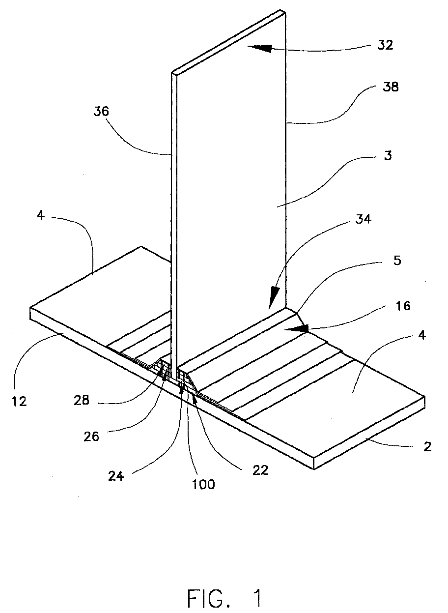
- Figure 1 shows the assembled structural element of one embodiment of this invention.
- Figures 2A and 2B show a top view and a side view of one embodiment of the rib-receiving member.
- FIG. 3 shows the structural details of the members of the structural element of one embodiment of the invention.
- Figure 4 shows the assembled structural element of another embodiment of this invention.
- Figure 4A shows layers of the assembled structural element of the embodiment of Fig. 4.
- Figures 5A and SB show a structure formed by engaging a rib member with two rib-receiving members.
- Figure 6 shows a top view of a structure formed by engaging a rib member with four rib-receiving members.
- Fig. 1 shows the assembled structural element of one embodiment of this invention.
- the composite structure comprises: a first member or face sheet 12 having an inner surface 4 and an outer surface 2; a rib-receiving member 5; a rib member 3 having a first end 34, a second end 32, a first edge 36 and a second edge 38.
- the first member may be, for example, a face sheet which is employed in an aerospace structure such as an aircraft wing or an internal aerospace structure such as a strut or the like.
- the first member may be fabricated from metal or a composite material, but is preferably fabricated from a composite material, as is further described herein.
- a second member which is similar to the first member may receive second end 32 of rib member 3 by using a second rib-receiving member, as shown, for example, in Figs. 5A and 5B.
- Rib-receiving member 5 comprises at least one cover sheet 16 which has an engagement opening therein for receiving first end 34 of rib member 3.
- Rib-receiving member 5 additionally comprises a plurality of rib-receiving elements (shown as 22, 24, 26, and 28) also having engagement openings (e.g. grooves) therein for receiving first end 34 of rib member 3.
- the cover sheet or sheets and the elements of rib-receiving member 5 are preferably made from a composite material which is machinable. In another embodiment, the rib-receiving elements and cover sheets may also be fabricated from metal.
- a plurality of anchoring elements 100 interconnect the rib-receiving elements.
- the anchoring elements 100 are preferably graphite pins known as Z-fibersTM or "Z-pins" available, for example, from Aztex, Inc., as will be understood by those skilled in the art.
- the composite material which may be used for the rib-receiving elements, cover sheets and first member is an epoxy resin reinforced with graphite fibers. More preferably, but not necessarily, the composite material is fabricated from a toughened epoxy resin system such as 977-3 available from Cytec Fiberite and a high strength and modulus graphite fiber system such as IM-7 available from Hexcell.
- a toughened epoxy resin system such as 977-3 available from Cytec Fiberite
- IM-7 high strength and modulus graphite fiber system
- other composite materials which may be used include, but are not limited to, TORAYCA T700S-12K-PW/3900-2 fabric or TORAYCA T800H-/3900-2 tape (both available from Toray). These materials are particularly suitable for use because of their high structural strength and stiffness.
- element 22 forms the base of the rib-receiving elements 22, 24, 26, and 28, with rib-receiving elements 24, 26, and 28 stacked sequentially upon element 22.
- the cover sheet 16 (and additional cover sheets, if employed) are shaped to permit stacking of the rib-receiving elements 22, 24, 26, and 28 under the cover sheet or sheets.
- second end 32 of rib member 3 may also engage another rib-receiving member (not shown in Figure 1) which is integral to a second member or face sheet (not shown in Figure 1).
- first edge 36 and second edge 38 may each also be engaged to other rib-receiving members (not shown in Figure 1) which are in turn integral to third and fourth members or face sheets (not shown in Figure 1).
- FIG. 2A To illustrate how the rib receiving member is constructed reference is now made to Figure 2A.
- cover sheets 14 and 16 are raised over rib-receiving elements 22, 24, 26, and 28 of the rib-receiving members.
- rib-receiving elements 22 is the widest element, and element 28 is the narrowest element.
- the rib-receiving elements may be adjoined to one another via adhesive, mechanical interconnection or other suitable means.
- cover sheets 16 and 14 are raised over the elements 22, 24, 26, and 28 of the rib-receiving member, the cover sheets assume a shape which is approximately trapezoidal to minimize the spaces between cover sheet 14 and each of the elements.
- element 22 forms the base of the rib-receiving member and resides on an optional base plate 13 which in turn resides on inner surface 4 of first member 12.
- the base plate 13 may also be fabricated from metal or a composite material.
- the rib-receiving elements, base plate, first member and cover sheet or sheets are all fabricated from a composite material, and the first member, rib-receiving elements and cover sheet or sheets are arranged as depicted, for example, in Fig. 2B and cocured to form the integrated combination of first member or face sheet 12 and rib-receiving member 5 (which in this embodiment is made up of base plate 13, rib-receiving elements 22, 24, 26, and 28 having opening 20 therein, and cover sheets 14 and 16 having opening 20 therein), as depicted in Figure 2B.
- cocuring means joining two or more uncured composite layers or components (e.g.
- curing temperatures are typically in the range of 250-350°F and the autoclave pressure is in the range of 85-100 psi held for approximately 6-7 hours, with the vacuum bag and components therein at vacuum.
- high temperature composite systems may be employed which typically require curing temperatures in the range of 500-700°F and pressures of 200-300 psi.
- cocuring is typically carried out by vacuum bagging the assembly of first member or face sheet 12 and rib-receiving member 5 and placing the assembly inside an autoclave where pressure and elevated temperatures are introduced.
- the pressure and temperatures are increased incrementally in a prescribed manner to effect a curing of the rib-receiving member and first member or face sheet into an integrated assembly.
- Use of cocuring to form the integrated assembly of the first member, rib-receiving elements and cover sheet or sheets advantageously avoids the necessity and expense associated with assembly tooling, which would otherwise be necessary to properly align and adjoin the first member, rib-receiving elements and cover sheet or sheets.
- each of rib-receiving elements 22, 24, 26 and 28 may be adjoined to one another via adhesive, mechanical interconnection or other suitable means.
- a paste adhesive such as EA 9394 available from Loctite Aerospace, FM 400 available from Cytec Fiberite or another suitable adhesive known to those skilled in the art may be used.
- rib-receiving elements 22, 24, 26 and 28 may be assisted in their load carrying capability by the resistance provided by cover sheet 16.
- Cover sheet 16 (or additional cover sheets, if employed) may be adjoined to inner surface 4 of first member 12 via an adhesive, mechanical interconnection or other suitable means.
- Base plate 13 may also be affixed to inner surface 4 of first member 12 via an adhesive, mechanical interconnection or other suitable means.
- the upper surface 15 of base plate 13 may also be affixed to element 22 using an adhesive, mechanical interconnection or other suitable means.
- the rib-receiving elements 22, 24, 26, and 28 of the rib receiving member and cover sheets 14 and 16 of the rib-receiving member may be made from a composite or other material which may be machined, formed or otherwise shaped. Accordingly, as shown in Figure 2B, an opening such as a groove 20 may be provided into the cover sheets 14 and 16 and into the rib-receiving elements 22, 24, 26, and 28.
- the groove 20 is suitably shaped and dimensioned to engage rib member 3 (as shown in Fig. 1) by aligning rib member 3 with groove 20 and inserting rib member 3 into the groove to form the composite structure shown in Figure 1.
- the groove-rib engagement provides structural support between the rib-receiving member 5 and rib member 3.
- Groove 20 is sized and arranged to receive rib member 3.
- a film adhesive, paste adhesive or other suitable adhesive is interposed between rib member 3 and groove 20 for adhering the exterior surface of rib member 3 to the rib-receiving member comprising groove 20.
- the rib member 3 and the integrated rib-receiving assembly 10 (which is the combination of first member or face sheet 12 and rib-receiving member 5) are preferably not cocured together, because such cocuring would require extensive curing and assembly tooling.
- the present invention advantageously reduces the necessity for such tooling, which is expensive and time-consuming to use.
- a solder or brazing material may also be used if the components are fabricated from metallic materials.
- rib member 3 has a rectangular shaped cross-section and preferably has a width slightly smaller than the width of the groove 20 so that the rib may be inserted into the groove while at the same time enabling the rib member 3 to be in contact with the inner surfaces of the groove by means of a joining medium (i.e. adhesive, solder or brazing material).
- a joining medium i.e. adhesive, solder or brazing material.
- the rib member and groove are arranged to form an enclosure which is approximately rectangular in shape.
- Anchoring elements 100 which interconnect the rib-receiving elements 22, 24, 26, and 28 and first member 12 are also shown. As previously discussed, in the embodiment of this invention in which the rib-receiving elements are made of a composite material, the anchoring elements are preferably graphite pins.
- rib member 3 comprises a plurality of rib elements 301, 302, 303, 304, 305, 306, 307, and 308, and each of the elements 22, 24, 26 and 28 of the rib-receiving member 5 comprise a plurality of layers.
- rib-receiving member elements 22, 24, 26, and 28 respectively comprise layers 221-228, 241-248, 261-268 and 281-288, as shown.
- the rib elements are preferably each fabricated from a composite material such as the graphite fiber/epoxy resin system previously described, although in other embodiments the rib elements may be fabricated from metal.
- the rib elements are composite materials such as the graphite fiber/epoxy resin system previously described
- joining of the rib elements may be achieved by curing the individual rib elements using the curing techniques previously described with respect to the cocuring of the first member or face sheet and rib-receiving member.
- the rib elements if fabricated from a composite material, should be cured to form the rib member separately from the cocuring step previously described with respect to fabrication of the integrated first member or face sheet and the rib-receiving member.
- Anchoring elements 301 interconnect rib-receiving elements 22, 24, 26, and 28 of the rib-receiving member 5, thereby preventing peeling away of the elements of the rib-receiving member.
- the anchoring elements 301 do not extend into the cover plates 16 and 14.
- the surfaces of all of the rib elements and rib-receiving elements are preferably smooth.
- the term smooth is intended to mean that the surfaces are substantially free of uneven regions which interfere with the bonding of the elements.
- the outer surfaces of the rib-receiving elements 22, 24, 26, and 28 have no interlocking formations machined into them.
- small scale and microscopic unevenness, which is inherent in manufacturing and may even promote bonding are not excluded.
- Rib 3 is preferably affixed to the rib-receiving assembly using an adhesive as previously described. This advantageously avoids cocuring of the rib and rib-receiving assembly and thereby avoids the necessity for bagging and autoclave curing of the rib and rib-receiving assembly.
- the adhesives used may be cured at an oven temperature with moderate clamping pressure to the entire assembly.
- the assembly may then be ultrasonically inspected and X-rayed to ensure that proper bonding of the rib to the rib-receiving assembly is achieved.
- FIG. 4 Another embodiment of the composite structure is illustrated by referring to Figure 4 herein.
- the embodiment of Figure 4 comprises a first member or face sheet 40 which comprises an outer surface 41, an inner surface 43, and a plurality of layers 410-419 therebetween.
- Layers 410-419 are shown in greater detail in Figure 4A.
- the layers 410-419 are a composite material such as the graphite fiber/epoxy resin system previously described, and layers 410-419 are joined together by curing.
- the embodiment of Figure 4 also comprises a rib-receiving member engaged to the inner surface 43 of the first member or face sheet 40.
- the rib-receiving member comprises a rib-receiving sleeve 48 (shown here as a substantially U-shaped element).
- the sleeve 48 has an open end for receiving the first end 64 of the rib member 6, which is shown as a single member in Figure 4 and which may be made up of a plurality of rib elements as described above with respect to Figure 3.
- the sleeve 48 also has a closed curved end 49.
- First and second sleeve support members 46 and 47 are disposed on each side of sleeve 48.
- the first and second sleeve support members comprise outer layers 461 and 471, respectively, and preferably one or more inner layers 462, 463, 472, and 473.
- a plurality of anchoring elements 501 interconnect individual layers 410-419 of the first member.
- the first member or face sheet, the rib-receiving sleeve and the first and second sleeve support members as well as the rib member may be made from a composite material such as the graphite fiber/epoxy resin system previously described, which is penetrable by the anchoring elements 501.
- the first and second sleeve support members 46 and 47 respectively comprising outer layers 461 and 471 and the inner layers 462, 463, 472, and 473, respectively are substantially symmetrically disposed on opposite sides of the substantially U-shaped rib-receiving sleeve 48. Inner layers 463 and 473 of the first and second sleeve support members contact the substantially U-shaped rib-receiving sleeve 48, as shown in Fig. 4.
- Each of the substantially symmetrically disposed layers 461, 462, 463, 471, 472, and 473 is preferably formed by using a tool to provide curvature, as will be well understood by those skilled in the art.
- the rib-receiving sleeve 48 comprises substantially vertical ends 503 and 511.
- the layers 461, 462, 463, 471, 472, and 473 also comprise substantially vertical ends.
- ends 503 and 511 are situated at substantially the same vertical height as the substantially vertical ends of layers 461, 462, 463, 471, 472, and 473.
- first member or face sheet 40, sleeve support members 46 and 47, and rib-receiving sleeve 48 are cocured as previously described to form a rib-receiving assembly, where all of these individual components are made of a composite material such as the graphite fiber/epoxy resin system previously described.
- the curved portion 49 and the substantially vertical walls 50 and 51 define a substantially U-shaped groove.
- a rib member 6 which may be formed of a composite material or layers of a composite material is aligned with the substantially U-shaped groove. First end 64 of the rib member is inserted into the groove. Preferably, rib member 6 has a height greater than the depth of the groove, so that, as shown in Figure 1, second end 62 of the rib member projects out of the rib-receiving member.
- the groove-rib engagement provides structural support between the rib-receiving member and the rib member 6.
- the groove of U-shaped sleeve 48 is sized and arranged to receive rib member 6.
- a film adhesive, paste adhesive or other suitable adhesive may be interposed between rib member 6 and the groove for adhering the rib member 6 to the rib-receiving member comprising U-shaped sleeve 48.
- rib member projects out from the rib-receiving member and may be used to engage another rib-receiving member to form a structure.
- Figures 5A and 5B illustrate side views of this embodiment of the invention.
- a first rib-receiving assembly 404 as described above with respect to any of Figs. 1-4 and the description provided herein comprises a first member 412 and a rib-receiving member 405, and a second rib-receiving assembly 504 as described above with respect to any of Figs. 1-4 and the description provided herein comprises a second member 512 and a rib-receiving member 505.
- a first rib-receiving assembly 404 as described above with respect to any of Figs. 1-4 and the description provided herein comprises a first member 412 and a rib-receiving member 405, and a second rib-receiving assembly 504 as described above with respect to any of Figs. 1-4 and the description provided herein comprises
- each rib-receiving member 405, 505 comprises a plurality of rib-receiving elements (but not shown in detail in Figs. 5A and 5B) as previously described, and each rib receiving member has machined or integrally formed grooves 40 and 50 therein, respectively.
- each of grooves 40 and 50 is aligned with a rib member 6 having ends 62 and 64 and edges 66 and 68. End 62 is inserted into groove 40 to form a structural element, in accordance with the illustrations in Figures 1-4. End 64 is then inserted into groove 50 to complete the structure.
- rib ends 62 and 64 are engaged to first and second rib-receiving assemblies 404 and 504, respectively, as shown. Additionally, rib edge 66 may be engaged to a third rib-receiving assembly (not shown in Figures 5A and 5B) and rib edge 68 may be engaged to a fourth rib-receiving assembly (not shown in Figures 5A and SB).
- the third and fourth rib-receiving assemblies have the structure of first and second rib-receiving assemblies 404 and 504. Such a design may be employed, for example, in an aircraft wing flap.
- Figure 6 shows a forward view from point "A" in Figure 5B of the embodiment of the structural element described herein in which rib ends 62 and 64 as well as rib edges 66 and 68 of rib 6 are engaged to rib receiving assemblies 404, 504, 604 and 704 in Figure 6. More specifically, in Figure 6, rib 6 has rib ends 62 and 64 and rib edges 66 and 68 (all shown as hidden edges). Rib end 62 engages rib receiving member 405 which is integral to first member or face sheet 412. Rib end 64 engages rib receiving member 505 which is integral to second member or face sheet 512. Rib edge 66 engages rib receiving member 605 which is integral to third member or face sheet 612.
- Rib edge 68 engages rib receiving member 705 which is integral to fourth member or face sheet 712.
- the rib-receiving assemblies 404, 504, 604, and 704 as depicted in Figure 6 may be of the types depicted in any of Figures 1-5 described herein.
Landscapes
- Engineering & Computer Science (AREA)
- Mechanical Engineering (AREA)
- Aviation & Aerospace Engineering (AREA)
- Laminated Bodies (AREA)
- Rod-Shaped Construction Members (AREA)
- Joining Of Building Structures In Genera (AREA)
Abstract
Description
- This invention relates to a structural element useful in aerospace applications, as well as a method of preparing such a structural element for use in aerospace applications, such as a structural element suitable as an aircraft component. In particular, in the present invention the structural element comprises a first member such as a face sheet, and at least one rib-receiving member integral to the first member, wherein the rib-receiving member comprises either: (i) a plurality of rib-receiving elements for receiving the rib member with at least one anchoring element interconnecting the rib-receiving elements; or (ii) a rib-receiving sleeve for receiving the rib member.
- Aircraft components including intake ducts, flooring and wing sections are often made of honeycomb material which is lightweight, rigid and capable of being fabricated in many shapes. Depending on the particular application, the use of such honeycomb material may be expensive, in terms of life cycle costs, and may require extensive maintenance and repair. In some circumstances, it is also not readily adaptable to the attachment of other components. This drawback may be overcome by reinforcing elements within the honeycomb, but this typically involves adding to the weight of the structural element and thus reducing the advantage of the low weight of the honeycomb material.
- Furthermore, honeycomb core structures suffer from susceptibility to moisture intrusion resulting from their open-cell construction. Even non-visible face sheet damage can create a path for moisture intrusion. When moisture condenses on the outside of an aircraft wing skin fabricated with honeycomb core panels, the pressure differential between the sandwich interior and the atmosphere during descent can force moisture into the honeycomb core. Repeated freeze/thaw cycles are also known to cause corrosion of aluminum honeycomb cores, and delamination of the face sheet from the core. Repair complications due to honeycomb core water intrusion represent an additional difficulty.
- Other problems with honeycomb core structures are the presence of undetected damage, cracked skins, poor radar transparency due to the metal foil and poor thermal insulation due to the conductivity of aluminum foil which is often a component of honeycomb structures.
- In U.S. Patent Nos. 5,273,806, 5,487,930, and 5,508,085, structural elements are disclosed which comprise two outer structures and an inner structure interposed between the two outer structures. The inner structure includes lateral and longitudinal ribs. The ribs may be bonded to the outer structures. Alternatively, the structures may be joined together by interlocking ribs and grooves. The grooves are typically formed on the inner surfaces of the outer structures to mate with the ribs of the inner structures. While the inner structures may be formed from metal or composite material, the outer structures are generally formed from metal with grooves machined into the metal structures. As a result, since the metal is typically more dense and less stiff than the composite material, the overall weight of the structural element increases while its stiffness is reduced.
- In accordance with a first aspect of the invention there is provided a structural element comprising:
- (a) a rib member having a first end and a second end;
- (b) a first member having an inner surface and an outer surface;
- (c) a rib-receiving member integral to the inner surface of the first member, wherein the rib-receiving member comprises a plurality of rib-receiving elements having openings therein for receiving the first end of the rib member and at least one cover sheet having an opening therein for receiving the first end of the rib member, and at least one anchoring element interconnecting the rib-receiving elements.
-
- In accordance with a second aspect of the present invention there is provided a structural element comprising:
- (a) a rib member having a first end and a second end;
- (b) a first member having an inner surface and an outer surface;
- (c) a first rib-receiving member integral to the inner surface of the first member, wherein the first rib-receiving member comprises a plurality of rib-receiving elements having openings therein for receiving the first end of the rib member and at least one cover sheet having an opening therein for receiving the first end of the rib member, and at least one anchoring element interconnecting the rib-receiving elements.
- (d) a second member having an inner surface and an outer surface; and
- (e) a second rib-receiving member integral to the inner surface of the second member, wherein the second rib-receiving member comprises a plurality of rib-receiving elements having openings therein for receiving the second end of the rib member and at least one cover sheet having an opening therein for receiving the second end of the rib member, and at least one anchoring element interconnecting the rib-receiving elements.
-
- In accordance with a third aspect of the present invention there is provided a structural element comprising:
- (a) a rib member having a first end and a second end;
- (b) a first member having an inner surface and an outer surface;
- (c) a first rib-receiving member integral to the inner surface of the first member, wherein the first rib-receiving member comprises a plurality of rib-receiving elements having openings therein for receiving the first end of the rib member and at least one cover sheet having an opening therein for receiving the first end of the rib member, and at least one anchoring element interconnecting the rib-receiving elements;
- (d) a second member having an inner surface and an outer surface;
- (e) a second rib-receiving member integral to the inner surface of the second member, wherein the second rib-receiving member comprises a plurality of rib-receiving elements having openings therein for receiving the second end of the rib member and at least one cover sheet having an opening therein for receiving the second end of the rib member, and at least one anchoring element interconnecting the rib-receiving elements, and at least one anchoring element interconnecting the rib-receiving elements;
- (f) a third member having an inner surface and an outer surface;
- (g) a third rib-receiving member integral to the inner surface of the third member, wherein the third rib-receiving member comprises a plurality of rib-receiving elements having openings therein for receiving the first edge of the rib member and at least one cover sheet having an opening therein for receiving the first edge of the rib member, and at least one anchoring element interconnecting the rib-receiving elements;
- (h) a fourth member having an inner surface and an outer surface; and
- (i) a fourth rib-receiving member integral to the inner surface of the fourth member, wherein the fourth rib-receiving member comprises a plurality of rib-receiving elements having openings therein for receiving the second edge of the rib member and at least one cover sheet having an opening therein for receiving the second edge of the rib member, and at least one anchoring element interconnecting the rib-receiving elements.
-
- In accordance with a fourth aspect of the present invention there is provided a method of preparation of the structural element of the invention, wherein the method comprises:
- (a) providing a rib member having a first end and a second end;
- (b) providing a first member having an inner surface and an outer surface;
- (c) engaging the first end of the rib member to a rib-receiving member engaged to the inner surface of the first member, wherein the rib-receiving member comprises a plurality of rib-receiving elements having openings therein which receive the first end of the rib member and at least one cover sheet having an opening therein which receives the first end of the rib member; and
- (d) interconnecting the rib-receiving elements by providing at least one anchoring element which is connectively engaged to the rib-receiving elements.
-
- In accordance with a fifth aspect of the present invention there is provided a method for forming a structural element comprising:
- (a) providing a rib member having a first end and a second end;
- (b) providing a first member having an inner surface and an outer surface;
- (c) engaging a first rib-receiving member to the inner surface of the first member, wherein the first rib-receiving member comprises a plurality of rib-receiving elements having openings therein for receiving the first end of the rib member and at least one cover sheet having an opening therein for receiving the first end of the rib member;
- (d) interconnecting the rib-receiving elements of the first rib-receiving member by providing at least one anchoring element which is connectively engaged to the rib-receiving element;
- (e) providing a second member having an inner surface and an outer surface;
- (f) engaging a second rib-receiving member integral to the inner surface of the second member, wherein the second rib-receiving member comprises a plurality of rib-receiving elements having openings therein for receiving the second end of the rib member and at least one cover sheet having an opening therein for receiving the second end of the rib member; and
- (g) interconnecting the rib-receiving elements of the second rib-receiving member by providing at least one anchoring element which is connectively engaged to the rib-receiving element.
-
- In accordance with a sixth aspect of the present invention there is provided a structural element comprising:
- (a) providing a rib member having a first end and a second end;
- (b) providing a first member having an inner surface and an outer surface;
- (c) engaging a first rib-receiving member to the inner surface of the first member, wherein the first rib-receiving member comprises a plurality of rib-receiving elements having openings therein for receiving the first end of the rib member and at least one cover sheet having a groove therein which receives the first end of the rib member;
- (d) interconnecting the rib-receiving elements of the first rib-receiving member by providing at least one anchoring element which is connectively engaged to the rib-receiving element;
- (e) providing a second member having an inner surface and an outer surface;
- (f) engaging a second rib-receiving member integral to the inner surface of the second member, wherein the second rib-receiving member comprises a plurality of rib-receiving elements having openings therein for receiving the second end of the rib member and at least one cover sheet having an opening therein for receiving the second end of the rib member;
- (g) interconnecting the rib-receiving elements of the second rib-receiving member by providing at least one anchoring element which is connectively engaged to the rib-receiving element;
- (h) providing a third member having an inner surface and an outer surface;
- (i) engaging a third rib-receiving member integral to the inner surface of the third member, wherein the third rib-receiving member comprises a plurality of rib-receiving elements having openings therein for receiving the first edge of the rib member and at least one cover sheet having an opening therein for receiving the first edge of the rib member;
- (j) interconnecting the rib-receiving elements of the third rib-receiving member by providing at least one anchoring element which is connectively engaged to the rib-receiving element;
- (k) providing a fourth member having an inner surface and an outer surface;
- (1) engaging a fourth rib-receiving member integral to the inner surface of the fourth member, wherein the fourth rib-receiving member comprises a plurality of rib-receiving elements having openings therein for receiving the second edge of the rib member and at least one cover sheet having an opening therein for receiving the second edge of the rib member; and
- (m) interconnecting the rib-receiving elements of the fourth rib-receiving member by providing at least one anchoring element which is connectively engaged to the rib-receiving element.
-
- In accordance with a seventh aspect of the present invention there is provided a structural element comprising:
- (a) a rib member having a first end and a second end;
- (b) a first member having an inner surface and an outer surface; and
- (c) a rib-receiving member integral to the inner surface of the first member, wherein the rib-receiving member comprises a rib-receiving sleeve having an open end for receiving the rib member and a closed end, a first sleeve support member and a second sleeve support member, wherein the first and second sleeve support members interconnect the rib-receiving sleeve to the inner face of the first member.
-
- In accordance with an eighth aspect of the present invention there is provided a structural element comprising:
- (a) a rib member having a first end and a second end;
- (b) a first member having an inner surface and an outer surface;
- (c) a first rib-receiving member integral to the inner surface of the first member, wherein the first rib-receiving member comprises a first rib-receiving sleeve having an open end for receiving the rib member and a closed end and two sleeve support members, wherein the sleeve support members are disposed on opposite sides of the first rib-receiving sleeve and interconnect the first rib-receiving sleeve to the inner face of the first member;
- (d) a second member having an inner surface and an outer surface; and
- (e) a second rib-receiving member integral to the inner surface of the second member, wherein the second rib-receiving member comprises a second rib-receiving sleeve having an open end for receiving the rib member and a closed end, and two sleeve support members, wherein the sleeve support members are disposed on opposite sides of the second rib-receiving sleeve and interconnect the second rib-receiving sleeve to the inner face of the second member.
-
- In accordance with a ninth aspect of the present invention there is provided a structural element comprising:
- (a) a rib member having a first end and a second end;
- (b) a first member having an inner surface and an outer surface;
- (c) a first rib-receiving member integral to the inner surface of the first member, wherein the first rib-receiving member comprises a first rib-receiving sleeve having an open end for receiving the rib member and a closed end, and two sleeve support members, wherein the sleeve support members are disposed on opposite sides of the first rib-receiving sleeve and interconnect the first rib-receiving sleeve to the inner face of the first member;
- (d) a second member having an inner surface and an outer surface;
- (e) a second rib-receiving member integral to the inner surface of the second member, wherein the second rib-receiving member comprises a second rib-receiving sleeve having an open end for receiving the rib member and a closed end, and two sleeve support members, wherein the sleeve support members are disposed on opposite sides of the second rib-receiving sleeve and interconnect the second rib-receiving sleeve to the inner face of the second member;
- (f) a third member having an inner surface and an outer surface;
- (g) a third rib-receiving member integral to the inner surface of the third member, wherein the third rib-receiving member comprises a third rib-receiving sleeve having an open end for receiving the rib member and a closed end, and two sleeve support members, wherein the sleeve support members are disposed on opposite sides of the third rib-receiving sleeve and interconnect the third rib-receiving sleeve to the inner face of the third member;
- (h) a fourth member having an inner surface and an outer surface; and
- (i) a fourth rib-receiving member integral to the inner surface of the fourth member, wherein the fourth rib-receiving member comprises a fourth rib-receiving sleeve having an open end for receiving the rib member and a closed end, and two sleeve support members, wherein the sleeve support members are disposed on opposite sides of the fourth rib-receiving sleeve and interconnect the fourth rib-receiving sleeve to the inner face of the fourth member.
-
- In accordance with a tenth aspect of the present invention there is provided a method of preparation of the structural element of the invention, the method comprising:
- (a) providing a rib member having a first end and a second end;
- (b) providing a first member having an inner surface and an outer surface; and
- (c) engaging the first end of the rib member to a rib-receiving member integral to the inner surface of the first member, wherein the rib-receiving member comprises a rib-receiving sleeve having an open first end for receiving the rib member and a closed second end, a first sleeve support member and a second sleeve support member wherein the first and second sleeve support members interconnect the sleeve to the inner face of the first member.
-
- In accordance with an eleventh aspect of the present invention there is provided a method for forming a structural element comprising:
- (a) providing a rib member having a first end and a second end;
- (b) providing a first member having an inner surface and an outer surface;
- (c) engaging a first rib-receiving member to the inner surface of the first member, wherein the first rib-receiving member comprises a first rib-receiving sleeve having an open end for receiving the rib member and a closed end, and two sleeve support members, wherein the sleeve support members are disposed on opposite sides of the first rib-receiving sleeve and interconnect the first rib-receiving sleeve to the inner face of the first member;
- (d) providing a second member having an inner surface and an outer surface; and
- (e) engaging a second rib-receiving member integral to the inner surface of the second member, wherein the second rib-receiving member comprises a second rib-receiving sleeve having an open end for receiving the rib member and a closed end, and two sleeve support members, wherein the sleeve support members are disposed on opposite sides of the second rib-receiving sleeve and interconnect the second rib-receiving sleeve to the inner face of the second member.
-
- In accordance with a twelfth aspect of the present invention there is provided a method for forming a structural element comprising:
- (a) providing a rib member having a first end and a second end;
- (b) providing a first member having an inner surface and an outer surface;
- (c) engaging a first rib-receiving member to the inner surface of the first member, wherein the first rib-receiving member comprises a first rib-receiving sleeve having an open end for receiving the rib member and a closed end, and two sleeve support members, wherein the sleeve support members are disposed on opposite sides of the first rib-receiving sleeve and interconnect the first rib-receiving sleeve to the inner face of the first member;
- (d) providing a second member having an inner surface and an outer surface;
- (e) engaging a second rib-receiving member integral to the inner surface of the second member, wherein the second rib-receiving member comprises a second rib-receiving sleeve having an open end for receiving the rib member and a closed end, and two sleeve support members, wherein the sleeve support members are disposed on opposite sides of the second rib-receiving sleeve and interconnect the second rib-receiving sleeve to the inner face of the second member;
- (f) providing a third member having an inner surface and an outer surface;
- (g) engaging a third rib-receiving member integral to the inner surface of the third member, wherein the third rib-receiving member comprises a third rib-receiving sleeve having an open end for receiving the rib member and a closed end, and two sleeve support members, wherein the sleeve support members are disposed on opposite sides of the third rib-receiving sleeve and interconnect the third rib-receiving sleeve to the inner face of the third member;
- (h) providing a fourth member having an inner surface and an outer surface; and
- (i) engaging a fourth rib-receiving member integral to the inner surface of the fourth member, wherein the fourth rib-receiving member comprises a fourth rib-receiving sleeve having an open end for receiving the rib member and a closed end, and two sleeve support members, wherein the sleeve support members are disposed on opposite sides of the fourth rib-receiving sleeve and interconnect the fourth rib-receiving sleeve to the inner face of the fourth member.
-
- Preferred features of the aspects of the invention defined herein are set out in the accompanying dependent claims set out hereinafter.
- Further preferred features of the aspects of the invention defined above - whether a structural element of a method relating thereto - are set out below.
- Preferably an adhesive is interposed between the first end of the rib member and the openings in the first rib-receiving member.
- Preferably the second end of the rib member projects out from the first rib-receiving member.
- Preferably each opening is a groove which comprises inner surfaces, and the rib member has a width smaller than the width of each groove and is in contact with the inner surfaces of each groove.
- Preferably each rib-receiving element is formed from metal.
- Preferably the rib member comprises a plurality of rib elements, and each rib element is formed from a metal.
- The structural element according to the present invention permits the elimination of extensive assembly tooling and reduced part count. The structural element of this invention also provides high strength, low weight, and improved stiffness.
- Unlike honeycomb structures, the structural element of this invention does not comprise small cellular areas that can trap moisture. In fact, the structure lends itself to direct venting and drainage systems to eliminate the accumulation of moisture. In addition, the structure does not have dissimilar metallic materials in the construction that can lead to galvanic corrosion.
- The structure's durability is also enhanced by several features. The bonded joint is loaded in double shear and hence reduces any tendency for peel stresses. The rib-receiving member (also known as a "build-up") provides a reinforced area for receiving any impact loads directly imparted to the rib member.
- The invention will now be further described, by way of illustration, with reference to the accompanying drawings.
- Figure 1 shows the assembled structural element of one embodiment of this invention.
- Figures 2A and 2B show a top view and a side view of one embodiment of the rib-receiving member.
- Figure 3 shows the structural details of the members of the structural element of one embodiment of the invention.
- Figure 4 shows the assembled structural element of another embodiment of this invention.
- Figure 4A shows layers of the assembled structural element of the embodiment of Fig. 4.
- Figures 5A and SB show a structure formed by engaging a rib member with two rib-receiving members.
- Figure 6 shows a top view of a structure formed by engaging a rib member with four rib-receiving members.
- Various embodiments of this invention are illustrated by reference to Figs. 1-4 herein. Fig. 1 shows the assembled structural element of one embodiment of this invention. The composite structure comprises: a first member or
face sheet 12 having aninner surface 4 and anouter surface 2; a rib-receivingmember 5; arib member 3 having afirst end 34, asecond end 32, afirst edge 36 and asecond edge 38. The first member may be, for example, a face sheet which is employed in an aerospace structure such as an aircraft wing or an internal aerospace structure such as a strut or the like. The first member may be fabricated from metal or a composite material, but is preferably fabricated from a composite material, as is further described herein. A second member (not shown) which is similar to the first member may receivesecond end 32 ofrib member 3 by using a second rib-receiving member, as shown, for example, in Figs. 5A and 5B. Rib-receivingmember 5 comprises at least onecover sheet 16 which has an engagement opening therein for receivingfirst end 34 ofrib member 3. Rib-receivingmember 5 additionally comprises a plurality of rib-receiving elements (shown as 22, 24, 26, and 28) also having engagement openings (e.g. grooves) therein for receivingfirst end 34 ofrib member 3. The cover sheet or sheets and the elements of rib-receivingmember 5 are preferably made from a composite material which is machinable. In another embodiment, the rib-receiving elements and cover sheets may also be fabricated from metal. - A plurality of anchoring
elements 100 interconnect the rib-receiving elements. The anchoringelements 100 are preferably graphite pins known as Z-fibers™ or "Z-pins" available, for example, from Aztex, Inc., as will be understood by those skilled in the art. - In one preferred embodiment, the composite material which may be used for the rib-receiving elements, cover sheets and first member is an epoxy resin reinforced with graphite fibers. More preferably, but not necessarily, the composite material is fabricated from a toughened epoxy resin system such as 977-3 available from Cytec Fiberite and a high strength and modulus graphite fiber system such as IM-7 available from Hexcell. In addition, other composite materials which may be used include, but are not limited to, TORAYCA T700S-12K-PW/3900-2 fabric or TORAYCA T800H-/3900-2 tape (both available from Toray). These materials are particularly suitable for use because of their high structural strength and stiffness.
- As depicted in Fig. 1,
element 22 forms the base of the rib-receivingelements elements element 22. As shown in Fig. 1, the cover sheet 16 (and additional cover sheets, if employed) are shaped to permit stacking of the rib-receivingelements second end 32 ofrib member 3 may also engage another rib-receiving member (not shown in Figure 1) which is integral to a second member or face sheet (not shown in Figure 1). In addition,first edge 36 andsecond edge 38 may each also be engaged to other rib-receiving members (not shown in Figure 1) which are in turn integral to third and fourth members or face sheets (not shown in Figure 1). - To illustrate how the rib receiving member is constructed reference is now made to Figure 2A. In the embodiment of Figure 2A, cover
sheets elements element 22 is the widest element, andelement 28 is the narrowest element). As discussed above, the rib-receiving elements may be adjoined to one another via adhesive, mechanical interconnection or other suitable means. Ascover sheets elements cover sheet 14 and each of the elements. In this embodiment,element 22 forms the base of the rib-receiving member and resides on anoptional base plate 13 which in turn resides oninner surface 4 offirst member 12. Thebase plate 13 may also be fabricated from metal or a composite material. - In one particularly preferred embodiment of this invention, the rib-receiving elements, base plate, first member and cover sheet or sheets are all fabricated from a composite material, and the first member, rib-receiving elements and cover sheet or sheets are arranged as depicted, for example, in Fig. 2B and cocured to form the integrated combination of first member or
face sheet 12 and rib-receiving member 5 (which in this embodiment is made up ofbase plate 13, rib-receivingelements opening 20 therein, and coversheets opening 20 therein), as depicted in Figure 2B. As referred to herein, "cocuring" means joining two or more uncured composite layers or components (e.g. two or more rib-receiving elements or a cover sheet to a rib-receiving member, etc.) in one cure cycle to form an integrated assembly. For the graphite fiber/epoxy systems described herein which may be employed in a preferred embodiment of this invention, curing temperatures are typically in the range of 250-350°F and the autoclave pressure is in the range of 85-100 psi held for approximately 6-7 hours, with the vacuum bag and components therein at vacuum. In other embodiments of this invention, high temperature composite systems may be employed which typically require curing temperatures in the range of 500-700°F and pressures of 200-300 psi. As will be well understood by those skilled in the art, cocuring is typically carried out by vacuum bagging the assembly of first member orface sheet 12 and rib-receivingmember 5 and placing the assembly inside an autoclave where pressure and elevated temperatures are introduced. As will be well understood by those skilled in the art, the pressure and temperatures are increased incrementally in a prescribed manner to effect a curing of the rib-receiving member and first member or face sheet into an integrated assembly. Use of cocuring to form the integrated assembly of the first member, rib-receiving elements and cover sheet or sheets advantageously avoids the necessity and expense associated with assembly tooling, which would otherwise be necessary to properly align and adjoin the first member, rib-receiving elements and cover sheet or sheets. - In another embodiment, each of rib-receiving
elements elements cover sheet 16. Cover sheet 16 (or additional cover sheets, if employed) may be adjoined toinner surface 4 offirst member 12 via an adhesive, mechanical interconnection or other suitable means.Base plate 13 may also be affixed toinner surface 4 offirst member 12 via an adhesive, mechanical interconnection or other suitable means. Theupper surface 15 ofbase plate 13 may also be affixed toelement 22 using an adhesive, mechanical interconnection or other suitable means. - The rib-receiving
elements sheets groove 20 may be provided into thecover sheets elements groove 20 is suitably shaped and dimensioned to engage rib member 3 (as shown in Fig. 1) by aligningrib member 3 withgroove 20 and insertingrib member 3 into the groove to form the composite structure shown in Figure 1. The groove-rib engagement provides structural support between the rib-receivingmember 5 andrib member 3. -
Groove 20 is sized and arranged to receiverib member 3. Preferably, a film adhesive, paste adhesive or other suitable adhesive is interposed betweenrib member 3 and groove 20 for adhering the exterior surface ofrib member 3 to the rib-receivingmember comprising groove 20. Therib member 3 and the integrated rib-receiving assembly 10 (which is the combination of first member orface sheet 12 and rib-receiving member 5) are preferably not cocured together, because such cocuring would require extensive curing and assembly tooling. The present invention advantageously reduces the necessity for such tooling, which is expensive and time-consuming to use. A solder or brazing material may also be used if the components are fabricated from metallic materials. - In one preferred embodiment,
rib member 3 has a rectangular shaped cross-section and preferably has a width slightly smaller than the width of thegroove 20 so that the rib may be inserted into the groove while at the same time enabling therib member 3 to be in contact with the inner surfaces of the groove by means of a joining medium (i.e. adhesive, solder or brazing material). Preferably, the rib member and groove are arranged to form an enclosure which is approximately rectangular in shape. - Anchoring
elements 100 which interconnect the rib-receivingelements first member 12 are also shown. As previously discussed, in the embodiment of this invention in which the rib-receiving elements are made of a composite material, the anchoring elements are preferably graphite pins. - Reference is now made to Figure 3, which illustrates the structural details of the members of the structural element of one embodiment of the invention. As shown in Fig. 3,
rib member 3 comprises a plurality ofrib elements elements member 5 comprise a plurality of layers. In the embodiment of Figure 3, rib-receivingmember elements element 22 resides onbase plate 13, which in turn resides on theinner face 4 ofmember 12. In addition,cover sheet 14 resides in part on theinner face 4 ofmember 12, and coversheet 14 also resides upon, in part, the upper face ofbase plate 13 and also contacts each of rib-receivingelements sheet 16 resides in part on theinner face 4 ofmember 12. Coversheet 16 also resides in part on the upper surface ofcover sheet 14 as shown. - Anchoring
elements 301 interconnect rib-receivingelements member 5, thereby preventing peeling away of the elements of the rib-receiving member. The anchoringelements 301 do not extend into thecover plates - The surfaces of all of the rib elements and rib-receiving elements are preferably smooth. The term smooth is intended to mean that the surfaces are substantially free of uneven regions which interfere with the bonding of the elements. For example, the outer surfaces of the rib-receiving
elements Rib 3 is preferably affixed to the rib-receiving assembly using an adhesive as previously described. This advantageously avoids cocuring of the rib and rib-receiving assembly and thereby avoids the necessity for bagging and autoclave curing of the rib and rib-receiving assembly. This is advantageous because of the material and labor costs associated therewith. In this embodiment, the adhesives used may be cured at an oven temperature with moderate clamping pressure to the entire assembly. The assembly may then be ultrasonically inspected and X-rayed to ensure that proper bonding of the rib to the rib-receiving assembly is achieved. - Another embodiment of the composite structure is illustrated by referring to Figure 4 herein. The embodiment of Figure 4 comprises a first member or
face sheet 40 which comprises anouter surface 41, aninner surface 43, and a plurality of layers 410-419 therebetween. Layers 410-419 are shown in greater detail in Figure 4A. As previously discussed, in one preferred embodiment the layers 410-419 are a composite material such as the graphite fiber/epoxy resin system previously described, and layers 410-419 are joined together by curing. - The embodiment of Figure 4 also comprises a rib-receiving member engaged to the
inner surface 43 of the first member orface sheet 40. The rib-receiving member comprises a rib-receiving sleeve 48 (shown here as a substantially U-shaped element). Thesleeve 48 has an open end for receiving thefirst end 64 of therib member 6, which is shown as a single member in Figure 4 and which may be made up of a plurality of rib elements as described above with respect to Figure 3. Thesleeve 48 also has a closedcurved end 49. First and secondsleeve support members sleeve 48. The first and second sleeve support members compriseouter layers inner layers elements 501 interconnect individual layers 410-419 of the first member. The first member or face sheet, the rib-receiving sleeve and the first and second sleeve support members as well as the rib member may be made from a composite material such as the graphite fiber/epoxy resin system previously described, which is penetrable by the anchoringelements 501. - The first and second
sleeve support members outer layers inner layers sleeve 48.Inner layers sleeve 48, as shown in Fig. 4. - Each of the substantially symmetrically disposed
layers sleeve 48 comprises substantially vertical ends 503 and 511. Preferably, thelayers layers face sheet 40,sleeve support members sleeve 48 are cocured as previously described to form a rib-receiving assembly, where all of these individual components are made of a composite material such as the graphite fiber/epoxy resin system previously described. - In this embodiment of the invention, the
curved portion 49 and the substantiallyvertical walls 50 and 51 define a substantially U-shaped groove. Arib member 6 which may be formed of a composite material or layers of a composite material is aligned with the substantially U-shaped groove. First end 64 of the rib member is inserted into the groove. Preferably,rib member 6 has a height greater than the depth of the groove, so that, as shown in Figure 1,second end 62 of the rib member projects out of the rib-receiving member. The groove-rib engagement provides structural support between the rib-receiving member and therib member 6. The groove ofU-shaped sleeve 48 is sized and arranged to receiverib member 6. Preferably, a film adhesive, paste adhesive or other suitable adhesive may be interposed betweenrib member 6 and the groove for adhering therib member 6 to the rib-receiving member comprisingU-shaped sleeve 48. - In another embodiment of this invention, the rib member projects out from the rib-receiving member and may be used to engage another rib-receiving member to form a structure. Figures 5A and 5B illustrate side views of this embodiment of the invention. In Figure 5A, a first rib-receiving
assembly 404 as described above with respect to any of Figs. 1-4 and the description provided herein comprises afirst member 412 and a rib-receivingmember 405, and a second rib-receivingassembly 504 as described above with respect to any of Figs. 1-4 and the description provided herein comprises asecond member 512 and a rib-receivingmember 505. In the embodiment of this invention depicted in Figs. 5A and 5B, each rib-receivingmember grooves grooves rib member 6 having ends 62 and 64 andedges End 62 is inserted intogroove 40 to form a structural element, in accordance with the illustrations in Figures 1-4.End 64 is then inserted intogroove 50 to complete the structure. - Again referring to Figures 5A and SB, in another embodiment of this invention rib ends 62 and 64 are engaged to first and second rib-receiving
assemblies rib edge 66 may be engaged to a third rib-receiving assembly (not shown in Figures 5A and 5B) andrib edge 68 may be engaged to a fourth rib-receiving assembly (not shown in Figures 5A and SB). The third and fourth rib-receiving assemblies have the structure of first and second rib-receivingassemblies rib 6 are engaged torib receiving assemblies rib 6 has rib ends 62 and 64 and rib edges 66 and 68 (all shown as hidden edges).Rib end 62 engagesrib receiving member 405 which is integral to first member orface sheet 412.Rib end 64 engagesrib receiving member 505 which is integral to second member orface sheet 512.Rib edge 66 engagesrib receiving member 605 which is integral to third member orface sheet 612.Rib edge 68 engagesrib receiving member 705 which is integral to fourth member orface sheet 712. The rib-receivingassemblies - It should be understood that various changes and modifications to the preferred embodiments described herein will be apparent to those skilled in the art. Such changes and modifications can be made without departing from the spirit and scope of this invention and without diminishing its attendant advantages. It is therefore intended that such changes and modifications be covered by the appended claims.
Claims (30)
- A structural element comprising:(a) a first member having an inner surface and an outer surface;(b) a rib member having a first end and a second end;(c) a first rib-receiving member integral to the inner surface of the first member, wherein the first rib-receiving member comprises a plurality of rib-receiving elements having openings therein for receiving the first end of the rib member and at least one cover sheet having an opening therein for receiving the first end of the rib member; and(d) at least one anchoring element interconnecting the rib-receiving elements of the first rib-receiving member.
- The structural element of Claim 1, wherein the first rib-receiving member comprises a plurality of rib-receiving elements which are adjoined to each other using an adhesive.
- The structural element of Claim 1, wherein each rib-receiving element is formed from a composite material.
- The structural element of Claim 3, wherein each rib-receiving element comprises a plurality of layers, and each layer is formed from a composite material.
- The structural element of Claim 1, wherein the rib member comprises a plurality of rib elements, and each rib element is formed from a composite material.
- The structural element of Claim 1, further comprising:(e) a second member having an inner surface and an outer surface;(f) a second rib-receiving member integral to the inner surface of the second member, wherein the second rib-receiving member comprises a plurality of rib-receiving elements having openings therein for receiving the second end of the rib member and at least one cover sheet having an opening therein for receiving the second end of the rib member; and(g) at least one anchoring element interconnecting the rib-receiving elements of the second rib-receiving member.
- The structural element of Claim 6, wherein the rib member comprises first and second edges perpendicular to the first and second ends of the rib member, and the structural element further comprises:(h) a third member having an inner surface and an outer surface;(i) a third rib-receiving member integral to the inner surface of the third member, wherein the third rib-receiving member comprises a plurality of rib-receiving elements having openings therein for receiving the first edge of the rib member and at least one cover sheet having an opening therein for receiving the first edge of the rib member;(j) at least one anchoring element interconnecting the rib-receiving elements of the third rib-receiving member;(k) a fourth member having an inner surface and an outer surface;(1) a fourth rib-receiving member integral to the inner surface of the fourth member, wherein the fourth rib-receiving member comprises a plurality of rib-receiving elements having openings therein for receiving the second edge of the rib member and at least one cover sheet having an opening therein for receiving the second edge of the rib member; and(m) at least one anchoring element interconnecting the rib-receiving elements of the fourth rib-receiving member.
- A method for forming a structural element comprising:(a) providing a first member having an inner surface and an outer surface;(b) providing a rib member having a first end and a second end;(c) engaging the first end of the rib member to a first rib-receiving member integral to the inner surface of the first member, wherein the first rib-receiving member comprises a plurality of rib-receiving elements having openings therein which receive the first end of the rib member, at least one cover sheet having an opening therein which receives the first end of the rib member, and at least one anchoring element interconnecting the rib-receiving elements.
- The method of Claim 8, wherein the first rib-receiving member comprises a plurality of rib-receiving elements which are adjoined to each other using an adhesive.
- The method of Claim 13, wherein each rib-receiving element is formed from a composite material.
- The method of Claim 8, wherein each rib-receiving element comprises a plurality of layers, and each layer is formed from a composite material.
- The method of Claim 8, wherein the rib member comprises a plurality of rib elements, wherein each rib element is formed from a composite material.
- The method of Claim 8, further comprising:(d) providing a second member having an inner surface and an outer surface; and(e) engaging the second end of the rib member to a second rib-receiving member integral to the inner surface of the second member, wherein the second rib-receiving member comprises a plurality of rib-receiving elements having openings therein for receiving the second end of the rib member, at least one cover sheet having an opening therein for receiving the second end of the rib member, and at least one anchoring element interconnecting the rib-receiving elements of the second rib-receiving member.
- The method of Claim 13, wherein the rib member comprises first and second edges perpendicular to the first and second ends of the rib member, and the method further comprises:(f) providing a third member having an inner surface and an outer surface;(g) engaging the first edge of the rib member to a third rib-receiving member integral to the inner surface of the third member, wherein the third rib-receiving member comprises a plurality of rib-receiving elements having openings therein for receiving the first edge of the rib member, at least one cover sheet having an opening therein for receiving the first edge of the rib member, and at least one anchoring element interconnecting the rib-receiving elements of the third rib-receiving member;(h) providing a fourth member having an inner surface and an outer surface; and(i) engaging the second edge of the rib member to a fourth rib-receiving member integral to the inner surface of the fourth member, wherein the fourth rib-receiving member comprises a plurality of rib-receiving elements having openings therein for receiving the second edge of the rib member, at least one cover sheet having an opening therein for receiving the second edge of the rib member, and at least one anchoring element interconnecting the rib-receiving elements of the fourth rib-receiving member.
- A structural element comprising:(a) a first member having an inner surface and an outer surface;(b) a rib member having a first end and a second end; and(c) a first rib-receiving member integral to the inner surface of the first member, wherein the first rib-receiving member comprises a first rib-receiving sleeve having an open first end for receiving the rib member and a closed second end, a first sleeve support member and a second sleeve support member, wherein the first and second sleeve support members are each located on the inner surface of the first member on opposite sides of the first rib-receiving sleeve.
- The structural element of Claim 15, wherein the first and second sleeve support members each comprise a plurality of layers including an inner layer, and the inner layers of the first and second sleeve support members each contact the first rib-receiving sleeve.
- The structural element of Claim 16, wherein the first member comprises a plurality of layers, and at least one anchoring element interconnects the plurality of layers of the first member.
- The structural element of Claim 15, wherein the first rib-receiving member comprises a plurality of rib-receiving elements which are adjoined to each other using an adhesive.
- The structural element of Claim 15, wherein the first member, first rib-receiving sleeve and first and second sleeve support members are each formed from a composite material.
- The structural element of Claim 19, wherein the first member and first and second sleeve support members each comprise a plurality of layers, and each layer is formed from a composite material.
- The structural element of Claim 15, wherein the first rib member comprises a plurality of rib elements, and each rib element is formed from a composite material.
- The structural element of Claim 15, further comprising:(d) a second member having an inner surface and an outer surface; and(e) a second rib-receiving member integral to the inner surface of the second member, wherein the second rib-receiving member comprises a second rib-receiving sleeve having an open end for receiving the rib member and a closed end, and two sleeve support members, wherein the sleeve support members are each located on the inner surface of the second member on opposite sides of the second rib-receiving sleeve.
- The structural element of Claim 22, wherein the rib member comprises first and second edges perpendicular to the first and second ends of the rib member, and the structural element further comprises:(f) a third member having an inner surface and an outer surface;(g) a third rib-receiving member integral to the inner surface of the third member, wherein the third rib-receiving member comprises a third rib-receiving sleeve having an open end for receiving the rib member and a closed end, and two sleeve support members, wherein the sleeve support members are each located on the inner surface of the third member and are disposed on opposite sides of the third rib-receiving sleeve;(h) a fourth member having an inner surface and an outer surface; and(i) a fourth rib-receiving member integral to the inner surface of the fourth member, wherein the fourth rib-receiving member comprises a fourth rib-receiving sleeve having an open end for receiving the rib member and a closed end, and two sleeve support members, wherein the sleeve support members are each located on the inner surface of the fourth member and are disposed on opposite sides of the fourth rib-receiving sleeve.
- A method for forming a structural element comprising:(a) providing a first member having an inner surface and an outer surface;(b) providing a rib member having a first end and a second end; and(c) engaging the first end of the rib member to a first rib-receiving member integral to the inner surface of the first member, wherein the first rib-receiving member comprises a first rib-receiving sleeve having an open first end for receiving the rib member and a closed second end, a first sleeve support member and a second sleeve support member, wherein the first and second sleeve support members are each located on the inner surface of the first member and are disposed on opposite sides of the first rib-receiving sleeve.
- The method of Claim 24, wherein the first member comprises a plurality of layers.
- The method of Claim 24, wherein the first member, rib member, first rib-receiving sleeve and first and second sleeve support members are each formed from a composite material.
- The method of Claim 24, wherein each sleeve support member comprises a plurality of layers, and each layer is formed from a composite material.
- The method of Claim 24, wherein the rib member comprises a plurality of rib elements, wherein each rib element is formed from a composite material.
- The method of Claim 24, further comprising:(d) providing a second member having an inner surface and an outer surface; and(e) engaging the second end of the rib member to a second rib-receiving member integral to the inner surface of the second member, wherein the second rib-receiving member comprises a second rib-receiving sleeve having an open end for receiving the rib member and a closed end, and two sleeve support members, wherein the sleeve support members are each located on the inner surface of the second member on opposite sides of the second rib-receiving sleeve.
- The method of Claim 29, wherein the rib member comprises first and second edges perpendicular to the first and second ends of the rib member, and the method further comprises:(f) providing a third member having an inner surface and an outer surface;(g) engaging the first edge of the rib member to a third rib-receiving member integral to the inner surface of the third member, wherein the third rib-receiving member comprises a third rib-receiving sleeve having an open end for receiving the rib member and a closed end, and two sleeve support members, wherein the sleeve support members are each located on the inner surface of the third member and are disposed on opposite sides of the third rib-receiving sleeve;(h) providing a fourth member having an inner surface and an outer surface; and(i) engaging the second edge of the rib member to a fourth rib-receiving member integral to the inner surface of the fourth member, wherein the fourth rib-receiving member comprises a fourth rib-receiving sleeve having an open end for receiving the rib member and a closed end, and two sleeve support members, wherein the sleeve support members are each located on the inner surface of the fourth member and are disposed on opposite sides of the fourth rib-receiving sleeve.
Applications Claiming Priority (2)
| Application Number | Priority Date | Filing Date | Title |
|---|---|---|---|
| US154178 | 1998-09-16 | ||
| US10/154,178 US7205066B1 (en) | 2002-05-23 | 2002-05-23 | Structural element with rib-receiving member |
Publications (3)
| Publication Number | Publication Date |
|---|---|
| EP1365081A2 true EP1365081A2 (en) | 2003-11-26 |
| EP1365081A3 EP1365081A3 (en) | 2004-12-15 |
| EP1365081B1 EP1365081B1 (en) | 2013-02-20 |
Family
ID=29400546
Family Applications (1)
| Application Number | Title | Priority Date | Filing Date |
|---|---|---|---|
| EP03252085A Expired - Lifetime EP1365081B1 (en) | 2002-05-23 | 2003-04-02 | Structural element with rib-receiving member |
Country Status (2)
| Country | Link |
|---|---|
| US (1) | US7205066B1 (en) |
| EP (1) | EP1365081B1 (en) |
Cited By (2)
| Publication number | Priority date | Publication date | Assignee | Title |
|---|---|---|---|---|
| WO2012136661A1 (en) * | 2011-04-07 | 2012-10-11 | Airbus Operations Gmbh | A method for the manufacture of a fibre composite component, a reinforcement element, and also a fibre composite component |
| EP3398439A1 (en) * | 2013-02-01 | 2018-11-07 | GEA Food Solutions Bakel B.V. | Food forming drum |
Families Citing this family (15)
| Publication number | Priority date | Publication date | Assignee | Title |
|---|---|---|---|---|
| EP1666354B1 (en) * | 2004-12-01 | 2010-09-29 | Airbus Operations GmbH | Structural component, process for manufacturing a structural component and use of a structural component for an aircraft skin |
| DE102005038856A1 (en) * | 2005-08-17 | 2007-02-22 | Airbus Deutschland Gmbh | Fastening system for attaching tail unit at fastening surface of airplane, has contact surfaces for attachment at tail unit and fastening surface, where contact surfaces comprise contact line and differentiating angle of specified degrees |
| GB0611804D0 (en) * | 2006-06-14 | 2006-07-26 | Airbus Uk Ltd | Improved aircraft component |
| DE102008006834A1 (en) * | 2008-01-30 | 2009-10-15 | Airbus Deutschland Gmbh | Connecting arrangement for connecting two stiffening elements of different cross-sectional profile for an aircraft or spacecraft, and a shell component |
| US7841835B2 (en) * | 2009-02-20 | 2010-11-30 | General Electric Company | Spar cap for wind turbine blades |
| US8262550B2 (en) | 2009-03-19 | 2012-09-11 | R. J. Reynolds Tobacco Company | Apparatus for inserting objects into a filter component of a smoking article |
| US8702397B2 (en) * | 2009-12-01 | 2014-04-22 | General Electric Company | Systems and methods of assembling a rotor blade for use in a wind turbine |
| CA2820004C (en) | 2010-12-28 | 2016-02-16 | Bell Helicopter Textron Inc. | Multi-directional load joint system |
| AT513412B1 (en) | 2012-09-17 | 2014-07-15 | Tannpapier Gmbh | Tipping paper |
| EP2808156B1 (en) | 2013-05-28 | 2017-07-12 | Airbus Operations GmbH | A shell segment of an aircraft and a production method |
| JP6090931B2 (en) | 2013-10-02 | 2017-03-08 | 三菱重工業株式会社 | Joints and aircraft structures |
| US10144203B2 (en) * | 2013-10-03 | 2018-12-04 | The Boeing Company | Pre-formed thermoplastic filler for thermoset structure |
| CA2987622A1 (en) | 2016-12-02 | 2018-06-02 | Stephen Gleason | Composition and method to form a composite core material |
| US11498656B1 (en) | 2021-04-26 | 2022-11-15 | Rohr, Inc. | Airfoil system with embedded electric device |
| US11724792B2 (en) | 2021-09-14 | 2023-08-15 | Rohr, Inc. | Composite airfoil for an aircraft |
Citations (3)
| Publication number | Priority date | Publication date | Assignee | Title |
|---|---|---|---|---|
| US5273806A (en) | 1991-10-03 | 1993-12-28 | Lockshaw James J | Structural element with interlocking ribbing |
| US5487930A (en) | 1991-10-03 | 1996-01-30 | Tolo, Inc. | Three structure structural element with interlocking ribbing |
| US5508085A (en) | 1991-10-03 | 1996-04-16 | Tolo, Inc. | Structural elements made with cores of fiber-reinforced plastic |
Family Cites Families (10)
| Publication number | Priority date | Publication date | Assignee | Title |
|---|---|---|---|---|
| DE2622163C3 (en) * | 1976-05-19 | 1983-05-26 | Messerschmitt-Bölkow-Blohm GmbH, 8000 München | Profile support made of fiber-reinforced material |
| DE2967605D1 (en) * | 1979-04-16 | 1986-08-07 | Grumman Aerospace Corp | Method of fastening a composite sub-structure and structural assembly |
| JPH0411225Y2 (en) | 1985-12-27 | 1992-03-19 | ||
| US5616376A (en) * | 1991-10-03 | 1997-04-01 | Lockshaw; James J. | Reticulated structural element |
| US5633053A (en) | 1991-10-03 | 1997-05-27 | Lockshaw; James J. | Structural element with intermediate ribbing support |
| AT398064B (en) * | 1992-07-01 | 1994-09-26 | Hoac Austria Flugzeugwerk Wr N | PLASTIC COMPOSITE PROFILE, ESPECIALLY WING SLEEVE FOR AIRCRAFT CONSTRUCTION |
| US5688426A (en) * | 1995-06-07 | 1997-11-18 | The Boeing Company | Hybrid metal webbed composite beam |
| US5849393A (en) | 1997-04-17 | 1998-12-15 | Mcdonnell Douglas Corporation | Structural element and method of making |
| US6374570B1 (en) | 2000-08-25 | 2002-04-23 | Lockheed Martin Corporation | Apparatus and method for joining dissimilar materials to form a structural support member |
| US6520706B1 (en) * | 2000-08-25 | 2003-02-18 | Lockheed Martin Corporation | Composite material support structures with sinusoidal webs and method of fabricating same |
-
2002
- 2002-05-23 US US10/154,178 patent/US7205066B1/en not_active Expired - Fee Related
-
2003
- 2003-04-02 EP EP03252085A patent/EP1365081B1/en not_active Expired - Lifetime
Patent Citations (3)
| Publication number | Priority date | Publication date | Assignee | Title |
|---|---|---|---|---|
| US5273806A (en) | 1991-10-03 | 1993-12-28 | Lockshaw James J | Structural element with interlocking ribbing |
| US5487930A (en) | 1991-10-03 | 1996-01-30 | Tolo, Inc. | Three structure structural element with interlocking ribbing |
| US5508085A (en) | 1991-10-03 | 1996-04-16 | Tolo, Inc. | Structural elements made with cores of fiber-reinforced plastic |
Cited By (4)
| Publication number | Priority date | Publication date | Assignee | Title |
|---|---|---|---|---|
| WO2012136661A1 (en) * | 2011-04-07 | 2012-10-11 | Airbus Operations Gmbh | A method for the manufacture of a fibre composite component, a reinforcement element, and also a fibre composite component |
| US10000050B2 (en) | 2011-04-07 | 2018-06-19 | Airbus Operations Gmbh | Method for the manufacture of a fibre composite component, a reinforcement element and also a fibre composite component |
| EP3398439A1 (en) * | 2013-02-01 | 2018-11-07 | GEA Food Solutions Bakel B.V. | Food forming drum |
| US10736329B2 (en) | 2013-02-01 | 2020-08-11 | Gea Food Solutions Bakel B.V. | Food forming concept |
Also Published As
| Publication number | Publication date |
|---|---|
| EP1365081A3 (en) | 2004-12-15 |
| EP1365081B1 (en) | 2013-02-20 |
| US7205066B1 (en) | 2007-04-17 |
Similar Documents
| Publication | Publication Date | Title |
|---|---|---|
| US7238409B1 (en) | Structural element with rib-receiving member | |
| EP1365081B1 (en) | Structural element with rib-receiving member | |
| EP0720529B1 (en) | A complex composite sandwich structure having a laminate disposed therein and a method for making the same | |
| US8128028B2 (en) | Internally stiffened composite panels and methods for their manufacture | |
| US7510757B2 (en) | Cellular composite grid-stiffened structure | |
| US7244487B2 (en) | Apparatus, system, and method of joining structural components with a tapered tension bond joint | |
| US8096504B2 (en) | Integrated aircraft structure in composite material | |
| EP0976650A2 (en) | Composite aircraft structures and their fabrication methods | |
| JP6342641B2 (en) | Circumferential splice for joining shell structures together | |
| RU2643678C2 (en) | Stiffening element and bending element from laminated composite material, reinforced by inter-layer metal sheets | |
| EP2507050B1 (en) | Sandwich structure having arrestment feature and method of making the same | |
| CA2515149C (en) | Contact stiffeners for structural skins | |
| EP0823374A2 (en) | One piece spacecraft frame | |
| US20100032524A1 (en) | Apparatuses and methods for joining composite members and other structural members in aircraft wing boxes and other structures | |
| US5849393A (en) | Structural element and method of making | |
| JPH0239920A (en) | Frame particularly for aircraft fugelage | |
| JP6714363B2 (en) | Apparatus or method for manufacturing a structure | |
| EP2455214B1 (en) | Method for making a fitting for joining the edges of composite sandwich panels | |
| US6117519A (en) | Composite core material, composite material and method of assembly | |
| EP2651759B1 (en) | Skew-angle radius filler to reduce the risk of delamination of a laminated stringer assembly | |
| EP2455625B1 (en) | Composite sandwich shell edge joint | |
| JP4396057B2 (en) | FRP laminate and FRP molding method | |
| US20040213953A1 (en) | Apparatus, system, and method of joining structural components with a tapered tension bond joint | |
| US20230382510A1 (en) | Composite core structures for aircraft | |
| EP4279754A1 (en) | Joints of composite frames for optics support structure |
Legal Events
| Date | Code | Title | Description |
|---|---|---|---|
| PUAI | Public reference made under article 153(3) epc to a published international application that has entered the european phase |
Free format text: ORIGINAL CODE: 0009012 |
|
| AK | Designated contracting states |
Kind code of ref document: A2 Designated state(s): AT BE BG CH CY CZ DE DK EE ES FI FR GB GR HU IE IT LI LU MC NL PT RO SE SI SK TR |
|
| AX | Request for extension of the european patent |
Extension state: AL LT LV MK |
|
| PUAL | Search report despatched |
Free format text: ORIGINAL CODE: 0009013 |
|
| AK | Designated contracting states |
Kind code of ref document: A3 Designated state(s): AT BE BG CH CY CZ DE DK EE ES FI FR GB GR HU IE IT LI LU MC NL PT RO SE SI SK TR |
|
| AX | Request for extension of the european patent |
Extension state: AL LT LV MK |
|
| RIC1 | Information provided on ipc code assigned before grant |
Ipc: 7B 64C 1/00 B Ipc: 7B 32B 3/12 B Ipc: 7E 04C 2/00 A Ipc: 7E 04C 2/36 B |
|
| 17P | Request for examination filed |
Effective date: 20050518 |
|
| AKX | Designation fees paid |
Designated state(s): AT BE BG CH CY CZ DE DK EE ES FI FR GB GR HU IE IT LI LU MC NL PT RO SE SI SK TR |
|
| 17Q | First examination report despatched |
Effective date: 20051004 |
|
| GRAP | Despatch of communication of intention to grant a patent |
Free format text: ORIGINAL CODE: EPIDOSNIGR1 |
|
| GRAS | Grant fee paid |
Free format text: ORIGINAL CODE: EPIDOSNIGR3 |
|
| GRAA | (expected) grant |
Free format text: ORIGINAL CODE: 0009210 |
|
| AK | Designated contracting states |
Kind code of ref document: B1 Designated state(s): AT BE BG CH CY CZ DE DK EE ES FI FR GB GR HU IE IT LI LU MC NL PT RO SE SI SK TR |
|
| REG | Reference to a national code |
Ref country code: GB Ref legal event code: FG4D |
|
| REG | Reference to a national code |
Ref country code: CH Ref legal event code: EP |
|
| REG | Reference to a national code |
Ref country code: AT Ref legal event code: REF Ref document number: 597646 Country of ref document: AT Kind code of ref document: T Effective date: 20130315 |
|
| REG | Reference to a national code |
Ref country code: IE Ref legal event code: FG4D |
|
| REG | Reference to a national code |
Ref country code: DE Ref legal event code: R096 Ref document number: 60343307 Country of ref document: DE Effective date: 20130418 |
|
| REG | Reference to a national code |
Ref country code: AT Ref legal event code: MK05 Ref document number: 597646 Country of ref document: AT Kind code of ref document: T Effective date: 20130220 |
|
| REG | Reference to a national code |
Ref country code: NL Ref legal event code: VDEP Effective date: 20130220 |
|
| PG25 | Lapsed in a contracting state [announced via postgrant information from national office to epo] |
Ref country code: BG Free format text: LAPSE BECAUSE OF FAILURE TO SUBMIT A TRANSLATION OF THE DESCRIPTION OR TO PAY THE FEE WITHIN THE PRESCRIBED TIME-LIMIT Effective date: 20130520 Ref country code: AT Free format text: LAPSE BECAUSE OF FAILURE TO SUBMIT A TRANSLATION OF THE DESCRIPTION OR TO PAY THE FEE WITHIN THE PRESCRIBED TIME-LIMIT Effective date: 20130220 Ref country code: ES Free format text: LAPSE BECAUSE OF FAILURE TO SUBMIT A TRANSLATION OF THE DESCRIPTION OR TO PAY THE FEE WITHIN THE PRESCRIBED TIME-LIMIT Effective date: 20130531 Ref country code: CY Free format text: LAPSE BECAUSE OF FAILURE TO SUBMIT A TRANSLATION OF THE DESCRIPTION OR TO PAY THE FEE WITHIN THE PRESCRIBED TIME-LIMIT Effective date: 20130220 Ref country code: SE Free format text: LAPSE BECAUSE OF FAILURE TO SUBMIT A TRANSLATION OF THE DESCRIPTION OR TO PAY THE FEE WITHIN THE PRESCRIBED TIME-LIMIT Effective date: 20130220 |
|
| PG25 | Lapsed in a contracting state [announced via postgrant information from national office to epo] |
Ref country code: PT Free format text: LAPSE BECAUSE OF FAILURE TO SUBMIT A TRANSLATION OF THE DESCRIPTION OR TO PAY THE FEE WITHIN THE PRESCRIBED TIME-LIMIT Effective date: 20130620 Ref country code: SI Free format text: LAPSE BECAUSE OF FAILURE TO SUBMIT A TRANSLATION OF THE DESCRIPTION OR TO PAY THE FEE WITHIN THE PRESCRIBED TIME-LIMIT Effective date: 20130220 Ref country code: GR Free format text: LAPSE BECAUSE OF FAILURE TO SUBMIT A TRANSLATION OF THE DESCRIPTION OR TO PAY THE FEE WITHIN THE PRESCRIBED TIME-LIMIT Effective date: 20130521 Ref country code: FI Free format text: LAPSE BECAUSE OF FAILURE TO SUBMIT A TRANSLATION OF THE DESCRIPTION OR TO PAY THE FEE WITHIN THE PRESCRIBED TIME-LIMIT Effective date: 20130220 Ref country code: BE Free format text: LAPSE BECAUSE OF FAILURE TO SUBMIT A TRANSLATION OF THE DESCRIPTION OR TO PAY THE FEE WITHIN THE PRESCRIBED TIME-LIMIT Effective date: 20130220 |
|
| PG25 | Lapsed in a contracting state [announced via postgrant information from national office to epo] |
Ref country code: DK Free format text: LAPSE BECAUSE OF FAILURE TO SUBMIT A TRANSLATION OF THE DESCRIPTION OR TO PAY THE FEE WITHIN THE PRESCRIBED TIME-LIMIT Effective date: 20130220 Ref country code: SK Free format text: LAPSE BECAUSE OF FAILURE TO SUBMIT A TRANSLATION OF THE DESCRIPTION OR TO PAY THE FEE WITHIN THE PRESCRIBED TIME-LIMIT Effective date: 20130220 Ref country code: CZ Free format text: LAPSE BECAUSE OF FAILURE TO SUBMIT A TRANSLATION OF THE DESCRIPTION OR TO PAY THE FEE WITHIN THE PRESCRIBED TIME-LIMIT Effective date: 20130220 Ref country code: NL Free format text: LAPSE BECAUSE OF FAILURE TO SUBMIT A TRANSLATION OF THE DESCRIPTION OR TO PAY THE FEE WITHIN THE PRESCRIBED TIME-LIMIT Effective date: 20130220 Ref country code: RO Free format text: LAPSE BECAUSE OF FAILURE TO SUBMIT A TRANSLATION OF THE DESCRIPTION OR TO PAY THE FEE WITHIN THE PRESCRIBED TIME-LIMIT Effective date: 20130220 Ref country code: EE Free format text: LAPSE BECAUSE OF FAILURE TO SUBMIT A TRANSLATION OF THE DESCRIPTION OR TO PAY THE FEE WITHIN THE PRESCRIBED TIME-LIMIT Effective date: 20130220 |
|
| PG25 | Lapsed in a contracting state [announced via postgrant information from national office to epo] |
Ref country code: MC Free format text: LAPSE BECAUSE OF FAILURE TO SUBMIT A TRANSLATION OF THE DESCRIPTION OR TO PAY THE FEE WITHIN THE PRESCRIBED TIME-LIMIT Effective date: 20130220 |
|
| PGFP | Annual fee paid to national office [announced via postgrant information from national office to epo] |
Ref country code: GB Payment date: 20130904 Year of fee payment: 11 |
|
| REG | Reference to a national code |
Ref country code: CH Ref legal event code: PL |
|
| PLBE | No opposition filed within time limit |
Free format text: ORIGINAL CODE: 0009261 |
|
| STAA | Information on the status of an ep patent application or granted ep patent |
Free format text: STATUS: NO OPPOSITION FILED WITHIN TIME LIMIT |
|
| PG25 | Lapsed in a contracting state [announced via postgrant information from national office to epo] |
Ref country code: IT Free format text: LAPSE BECAUSE OF FAILURE TO SUBMIT A TRANSLATION OF THE DESCRIPTION OR TO PAY THE FEE WITHIN THE PRESCRIBED TIME-LIMIT Effective date: 20130220 |
|
| 26N | No opposition filed |
Effective date: 20131121 |
|
| REG | Reference to a national code |
Ref country code: IE Ref legal event code: MM4A |
|
| PG25 | Lapsed in a contracting state [announced via postgrant information from national office to epo] |
Ref country code: CH Free format text: LAPSE BECAUSE OF NON-PAYMENT OF DUE FEES Effective date: 20130430 Ref country code: DE Free format text: LAPSE BECAUSE OF NON-PAYMENT OF DUE FEES Effective date: 20131101 Ref country code: LI Free format text: LAPSE BECAUSE OF NON-PAYMENT OF DUE FEES Effective date: 20130430 |
|
| REG | Reference to a national code |
Ref country code: FR Ref legal event code: ST Effective date: 20131231 |
|
| REG | Reference to a national code |
Ref country code: DE Ref legal event code: R119 Ref document number: 60343307 Country of ref document: DE Effective date: 20131101 |
|
| PG25 | Lapsed in a contracting state [announced via postgrant information from national office to epo] |
Ref country code: FR Free format text: LAPSE BECAUSE OF NON-PAYMENT OF DUE FEES Effective date: 20130430 |
|
| PG25 | Lapsed in a contracting state [announced via postgrant information from national office to epo] |
Ref country code: IE Free format text: LAPSE BECAUSE OF NON-PAYMENT OF DUE FEES Effective date: 20130402 |
|
| GBPC | Gb: european patent ceased through non-payment of renewal fee |
Effective date: 20140402 |
|
| PG25 | Lapsed in a contracting state [announced via postgrant information from national office to epo] |
Ref country code: GB Free format text: LAPSE BECAUSE OF NON-PAYMENT OF DUE FEES Effective date: 20140402 |
|
| PG25 | Lapsed in a contracting state [announced via postgrant information from national office to epo] |
Ref country code: TR Free format text: LAPSE BECAUSE OF FAILURE TO SUBMIT A TRANSLATION OF THE DESCRIPTION OR TO PAY THE FEE WITHIN THE PRESCRIBED TIME-LIMIT Effective date: 20130220 |
|
| PG25 | Lapsed in a contracting state [announced via postgrant information from national office to epo] |
Ref country code: LU Free format text: LAPSE BECAUSE OF NON-PAYMENT OF DUE FEES Effective date: 20130402 Ref country code: HU Free format text: LAPSE BECAUSE OF FAILURE TO SUBMIT A TRANSLATION OF THE DESCRIPTION OR TO PAY THE FEE WITHIN THE PRESCRIBED TIME-LIMIT; INVALID AB INITIO Effective date: 20030402 |