EP1364828A2 - Element for a trailer with walking-floor - Google Patents
Element for a trailer with walking-floor Download PDFInfo
- Publication number
- EP1364828A2 EP1364828A2 EP03010769A EP03010769A EP1364828A2 EP 1364828 A2 EP1364828 A2 EP 1364828A2 EP 03010769 A EP03010769 A EP 03010769A EP 03010769 A EP03010769 A EP 03010769A EP 1364828 A2 EP1364828 A2 EP 1364828A2
- Authority
- EP
- European Patent Office
- Prior art keywords
- clamping
- guide rail
- cylinder
- component according
- trailer
- Prior art date
- Legal status (The legal status is an assumption and is not a legal conclusion. Google has not performed a legal analysis and makes no representation as to the accuracy of the status listed.)
- Withdrawn
Links
Images


Classifications
-
- B—PERFORMING OPERATIONS; TRANSPORTING
- B60—VEHICLES IN GENERAL
- B60P—VEHICLES ADAPTED FOR LOAD TRANSPORTATION OR TO TRANSPORT, TO CARRY, OR TO COMPRISE SPECIAL LOADS OR OBJECTS
- B60P1/00—Vehicles predominantly for transporting loads and modified to facilitate loading, consolidating the load, or unloading
- B60P1/006—Vehicles predominantly for transporting loads and modified to facilitate loading, consolidating the load, or unloading charge and discharge with pusher plates
-
- B—PERFORMING OPERATIONS; TRANSPORTING
- B62—LAND VEHICLES FOR TRAVELLING OTHERWISE THAN ON RAILS
- B62D—MOTOR VEHICLES; TRAILERS
- B62D63/00—Motor vehicles or trailers not otherwise provided for
- B62D63/06—Trailers
- B62D63/061—Foldable, extensible or yielding trailers
Definitions
- the invention relates to a component for a trailer, one with the chassis has connected bottom surface, comprising a relative to the bottom surface of the trailer on this movable partial floor surface, a relative to the movable partial floor surface sliding end wall and actuators for the sliding movements of partial floor area and end wall, whereby for the displacement of the partial floor area above the bottom surface of the trailer is provided a first sliding cylinder, on the one hand connected to the partial floor area and on the other hand to the floor area of the trailer is connectable and for the displacement of the end wall along the partial floor surface second sliding cylinder is provided, the piston with the movable end wall and whose cylinder is connected to the partial floor surface.
- the inventor has now taken on the task of a rational arrangement for the To create displacement of the bulkhead, in which the stroke of the displacement required sliding cylinder is low, so that the disadvantages of a telescopic cylinder avoided and cheaper hydraulic cylinders can be used.
- the guide rail runs together along the two through the second sliding cylinder connected clamping devices relative to each other and relative to the guide rail are arranged displaceably, the first clamping device with the displaceable End wall and the piston of the second sliding cylinder and the second Clamping device is connected to the cylinder of the sliding cylinder.
- the clamping device connected to the front wall is locked in the guide rail, by extending the piston, it becomes its Lock released other clamping device along the guide rail again a bit moved to the front end of the partial floor area.
- the clamping device connected to the front wall and locking the other Clamping device retracts the piston of the cylinder and takes the end wall via the clamping device connected to it.
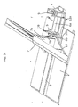
- a sliding cylinder 1 with its closed cylinder end 1 a attached not shown fixed bottom of a sliding trailer. His piston 1b is with the bottom of the sliding floor 2 of the component connected.
- His Clamping devices 4 and 5 are slidably arranged.
- the two clamps 4 and 5 are bridged by a sliding cylinder 6 so that the closed end of the Cylinder 6a with the clamping device 4 and the end of the piston 6b with the Clamping device 5 is connected.
- the clamping device 5 is also with a Front wall 7 firmly connected, along the sliding floor 2 for emptying the bulk material located on this floor can be moved towards the end of the hanger.
- a control unit 8 which controls the activity of the hydraulic cylinders in chronological succession, is also provided on the component.
- the following workflow results:
- the sliding floor 2 is first moved over about half of the fixed trailer floor to the rear end of the trailer.
- the clamping device 4 is clamped on the guide rail 3.
- the clamping device 5 is released from its clamping position and the piston 6b of the sliding cylinder 6 is extended.
- the end wall 7 is displaced along the displacement floor 2 by a distance which corresponds to the stroke distance of the piston.
- the clamping device 5 is clamped on the guide rail 3, the clamping device 4 is released from its clamping position and the cylinder 6a is retracted via the piston 6b and clamped again on the guide rail.
- This process is then repeated, ie the clamping device 5 is released again, the clamping device 4 is clamped again, the piston 6b is extended and the end wall 7 is displaced a further distance along the sliding floor 2.
- the chronological sequence of the actuations of the sliding cylinder 6 and the working cylinders 9 and 10 required for the settings of the clamping devices 4 and 5 is triggered either mechanically or electrically and forwarded to the control device 8.
- the clamping device 4 can be freely moved on the guide rail 3. you Working cylinder 9 is retracted, the clamping parts 11, which are described in more detail below are not in engagement with the guide rail 3. The clamping device 5 is however, in the clamped position. Your working cylinder 10 is extended and has its clamping parts 11 brought into engagement with the guide rail 3.
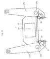
- the clamping device 5 is firmly connected to the end wall 7 via a flap 13.
- the free end of the piston 6b is also firmly connected to the end wall 7 via an arm 13b of the flap 13 with the end wall 7.
- the cylinder 6a can be pushed through an opening 16 in the clamping device 5 and in a holding part 7a of the end wall 7 by moving the clamping device 4.
- the two clamping devices 5 and 4 approach each other until a contact part 12a, the clamping device 4 comes into contact with a contact arm 12b on the clamping device 5. This position is shown in Fig. 4.
- a pulse is sent to the control unit 8, which ensures that the working cylinder 10 retracts, releases the clamping device 5 from its engagement with the guide rail 3 and brings the clamping device 4 into the clamping position with the guide rail 3 by cutting out its working cylinder 9.
- Various solutions are known for the design of the clamping devices 4 and 5.
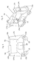
- 5 shows an end view of a clamping part 4 or 5.
- a supporting part 15 bridging the guide rail 3 with a centrally arranged opening 16 for the passage of the sliding cylinder 6a has articulated levers 17a, b on its two lower ends 15a, b, which project upwards. Their upper ends are articulated at 18a, b to the end of the working cylinder 9a or 10a on the one hand and on the other hand to the end of the piston 9b or 10b.
- the opposite lower end of the lever 17a and b is designed as a clamping part 19, which is shown in FIGS. 7, b and 8 in detail.
- the clamping device 4 or 5 is shown in perspective.
- the component 15 comprises two plates 15a and 15b which are arranged at intervals from one another and in which the levers 17a, b, which are also formed in pairs, are held.
- 7a and 7b an embodiment of the clamping parts 19 is shown.
- the clamping part 19 is in the open position in FIG. 7a and in the closed position in FIG. 7b.
- the clamping part 19 comprises a roller-shaped part 20 with a rectangular sector cutout 20a. This roller 20 is mounted in a shell 21 adapted to the diameter of the roller 20.
- FIG. 8 A further embodiment of the clamping parts 19 is shown greatly enlarged in FIG. 8. This is a grid guide for the clamping parts.
- the guide rail 3 is designed on its underside in the form of a toothed rack 25.
- the pairs of levers 17a and 17b are connected to one another at their lower ends by toothed racks 26. In the closed position, the racks 26 press against the racks 25 of the guide rail 3.
Abstract
Description
Die Erfindung betrifft ein Bauteil für einen Anhänger, der eine mit dem Fahrgestell verbundene Bodenfläche aufweist, umfassend eine relativ zur Bodenfläche des Anhängers auf dieser verschiebbare Teilbodenfläche, eine relativ zur verschiebbaren Teilbodenfläche verschiebbare Stirnwand und Betätigungsvorrichtungen für die Verschiebebewegungen von Teilbodenfläche und Stirnwand, wobei für die Verschiebung der Teilbodenfläche über die Bodenfläche des Anhängers ein erster Schiebezylinder vorgesehen ist, der einerseits mit der Teilbodenfläche verbunden und andererseits mit der Bodenfläche des Anhängers verbindbar ist und für die Verschiebung der Stirnwand längs der Teilbodenfläche ein zweiter Schiebezylinder vorgesehen ist, dessen Kolben mit der verschiebbaren Stirnwand und dessen Zylinder mit der Teilbodenfläche verbunden ist.The invention relates to a component for a trailer, one with the chassis has connected bottom surface, comprising a relative to the bottom surface of the trailer on this movable partial floor surface, a relative to the movable partial floor surface sliding end wall and actuators for the sliding movements of partial floor area and end wall, whereby for the displacement of the partial floor area above the bottom surface of the trailer is provided a first sliding cylinder, on the one hand connected to the partial floor area and on the other hand to the floor area of the trailer is connectable and for the displacement of the end wall along the partial floor surface second sliding cylinder is provided, the piston with the movable end wall and whose cylinder is connected to the partial floor surface.
Ein solches Bauteil ist bereits aus dem deutschen Gebrauchsmuster Nr. 2981 8105.3 bekannt. Die Stirnwand wird in der bekannten Vorrichtung mittels eines Hydraulikzylinders verschoben, der ein mit der Stirnwand verbundenes Hebelgestänge betätigt. Diese Anordnung ist konstruktiv aufwendig. Verwendet man aber anstelle dieser Anordnung einen Teleskopzylinder, so stellt man fest, daß bei der in der Regel erforderlichen Hublänge die der Länge des Anhängers entsprechen muß, sich die Kolbenstange in der Mitte verbiegen kann. Darüber hinaus erfordert ein Teleskopzylinder eine hohe Leistung der Hydraulikpumpe des Schleppers. Solche Hydraulikanlagen sind aber nicht bei allen im Einsatz befindlichen Schleppern oder Traktoren vorhanden. Such a component is already from German utility model No. 2981 8105.3 known. The end wall is in the known device by means of a Hydraulic cylinder moved, the lever linkage connected to the front wall actuated. This arrangement is structurally complex. But you use instead of this Arrangement of a telescopic cylinder, you can see that in the rule required stroke length which must correspond to the length of the trailer, the Can bend the piston rod in the middle. It also requires a telescopic cylinder high performance of the tractor's hydraulic pump. Such hydraulic systems are but not available on all tractors or tractors in use.
Der Erfinder hat sich nun die Aufgabe gestellt, eine rationelle Anordnung für die Verschiebung der Stirnwand zu schaffen, bei der der Hub des für den Verschiebevorgang erforderlichen Schiebezylinders gering ist, so daß die Nachteile eines Teleskopzylinders vermieden und kostengünstigere Hydraulikzylinder verwendet werden können.The inventor has now taken on the task of a rational arrangement for the To create displacement of the bulkhead, in which the stroke of the displacement required sliding cylinder is low, so that the disadvantages of a telescopic cylinder avoided and cheaper hydraulic cylinders can be used.
Dies wird nach der Erfindung dadurch erreicht, daß längs der Teilbodenfläche eine Führungsschiene verläuft, längs der zwei durch den zweiten Schiebezylinder miteinander verbundene Klemmvorrichtungen relativ zueinander und relativ zur Führungsschiene verschiebbar angeordnet sind, wobei die erste Klemmvorrichtung mit der verschiebbaren Stirnwand und dem Kolben des zweiten Schiebezylinders und die zweite Klemmvorrichtung mit dem Zylinder des Schiebezylinders verbunden ist.This is achieved according to the invention in that a along the partial floor area The guide rail runs together along the two through the second sliding cylinder connected clamping devices relative to each other and relative to the guide rail are arranged displaceably, the first clamping device with the displaceable End wall and the piston of the second sliding cylinder and the second Clamping device is connected to the cylinder of the sliding cylinder.
Durch diese Anordnung läßt sich folgender Arbeitsvorgang erreichen. Ist die mit der Stirnwand verbundene Klemmvorrichtung aus ihrem Eingriff mit der Führungsschiene gelöst und die andere Klemmvorrichtung fest auf der Führungsschiene arretiert, so wird die Stirnwand beim Ausfahren des Kolbens des zweiten Schiebezylinders um die Länge des Kolbenhubes der Teilbodenfläche verschoben. Wird anschließend die mit der Stirnwand verbundene Klemmvorrichtung auf der Führungsschiene arretiert und die andere aus ihrer Arretierung mit der Führungsschiene gelöst, dann läßt sich durch Verschieben dieser gelösten Klemmvorrichtung längs der Führungsschiene der Kolben des Schiebezylinders wieder einfahren. Durch Wiederholung dieses Vorgangs läßt sich in Schritten, die dem Kolbenhub des Hydraulikzylinders entsprechen, die Stirnwand längs der Teilbodenfläche verschieben. Auf einen Hydraulikzylinder mit großer Hublänge kann auf diese Weise verzichtet werden.With this arrangement, the following operation can be achieved. Is that with the End wall connected clamping device from its engagement with the guide rail loosened and the other clamping device firmly locked on the guide rail, so the Front wall when extending the piston of the second sliding cylinder by the length of the Piston stroke of the partial floor area shifted. Then the one with the front wall connected clamping device locked on the guide rail and the other from her Locked with the guide rail released, then by moving this released clamping device along the guide rail of the piston of the sliding cylinder retract again. By repeating this process, steps can be taken that correspond to the The piston stroke of the hydraulic cylinder corresponds to the front wall along the partial floor surface move. A hydraulic cylinder with a large stroke length can be used in this way to be dispensed with.
Will man die Stirnwand wieder in ihre ursprüngliche Lage zurückziehen, so verläuft der beschriebene Vorgang umgekehrt. Die mit der Stirnwand verbundene Klemmvorrichtung wird in der Führungsschiene arretiert, durch Ausfahren des Kolbens wird die aus ihrer Arretierung gelöste andere Klemmvorrichtung längs der Führungsschiene wieder ein Stück zum vorderen Ende der Teilbodenfläche verschoben. Durch anschließend erneute Lösung der mit der Stirnwand verbundenen Klemmvorrichtung und Arretierung der anderen Klemmvorrichtung wird der Kolben des Zylinders eingefahren und nimmt die Stirnwand über die mit ihr verbundene Klemmvorrichtung mit. If you want to pull the front wall back into its original position, it runs process described vice versa. The clamping device connected to the front wall is locked in the guide rail, by extending the piston, it becomes its Lock released other clamping device along the guide rail again a bit moved to the front end of the partial floor area. By subsequent solution the clamping device connected to the front wall and locking the other Clamping device retracts the piston of the cylinder and takes the end wall via the clamping device connected to it.
Einzelheiten über die vorzugsweise Ausbildung der Klemmvorrichtung ergeben sich aus den Unteransprüchen und der nachstehenden Beschreibung anhand der Zeichnung. Hierin zeigen
- Fig. 1
- eine schematische Darstellung des erfindungsgemäßen Bauteils mit Klemmvorrichtungen.
- Fig. 2
- eine Ausführungsform des in Fig. 1 schematisch dargestellten Bauteils, ohne Stirnwand,
- Fig. 3
- das erfindungsgemäße Bauteil in perspektivischer Darstellung bei ausgefahrenem Kolben des Schiebezylinders,
- Fig. 4
- das erfindungsgemäße Bauteil in perspektivischer Darstellung bei eingefahrenem Kolben des Schiebezylinders,
- Fig. 5
- eine Vorderansicht einer Ausbildung der Klemmvorrichtung,
- Fig. 6
- eine perspektivische Darstellung der Klemmvorrichtung nach Fig. 5,
- Fig.7a
- eine Darstellung des Klemmteiles der Klemmvorrichtung nach Fig. 5 in Offenstellung,
- Fig.7b
- eine Darstellung des Klemmteiles der Vorrichtung nach Fig. 5 in Schließstellung,
- Fig. 8
- eine weitere Ausbildung der Klemmvorrichtung in perspektivischer Darstellung, wobei die eine Klemmvorrichtung in Verschlußstellung und die andere Klemmvorrichtung in Offenstellung dargestellt ist.
- Fig. 1
- is a schematic representation of the component according to the invention with clamping devices.
- Fig. 2
- 1 shows an embodiment of the component shown schematically in FIG. 1, without an end wall,
- Fig. 3
- the component according to the invention in a perspective view with the piston of the sliding cylinder extended,
- Fig. 4
- the component according to the invention in a perspective view with the piston of the sliding cylinder retracted,
- Fig. 5
- a front view of an embodiment of the clamping device,
- Fig. 6
- 5 shows a perspective illustration of the clamping device according to FIG. 5,
- 7a
- 5 shows the clamping part of the clamping device according to FIG. 5 in the open position,
- Figure 7b
- 5 shows the clamping part of the device according to FIG. 5 in the closed position,
- Fig. 8
- a further embodiment of the clamping device in a perspective view, the one clamping device is shown in the closed position and the other clamping device in the open position.
In Fig. 1 ist das Aufbauprinzip des erfindungsgemäßen Bauteiles lür Schiebeanhänger
dargestellt. Ein Schiebezylinder 1 wird mit seinem verschlossenen Zylinderende 1a am
nicht dargestellten festen Boden eines Schiebeanhängers angehängt. Sein Kolben 1b ist mit
der Unterseite des Verschiebebodens 2 des Bauteils verbunden. Längs der Mittelachse des
Verschiebebodens 2 verläuft eine Führungsschiene 3. Auf dieser sind zwei
Klemmvorrichtungen 4 bzw. 5 verschiebbar angeordnet. Die beiden Klemmvorrichtungen
4 und 5 sind durch einen Schiebezylinder 6 so überbrückt, daß das geschlossene Ende des
Zylinders 6a mit der Klemmvorrichtung 4 und das Ende des Kolbens 6b mit der
Klemmvorrichtung 5 verbunden ist. Die Klemmvorrichtung 5 ist ferner mit einer
Stirnwand 7 fest verbunden, die längs des Verschiebebodens 2 für die Entleerung des auf
diesem Boden befindlichen Schüttgutes zum Auhängerende hin verschiebbar ist. 1 shows the construction principle of the component according to the invention for sliding trailers
shown. A sliding
Ein Steuergerät 8, das die Tätigkeit der Hydraulikzylinder in zeitlicher Aufeinanderfolge
steuert, ist ebenfalls am Bauteil vorgesehen.
Um ein auf dem Verschiebeboden 2 befindliches Schüttgut zum einen Ende hin zu
verschieben, ergibt sich folgender Arbeitsablauf:
Mittels des Schiebezylinders 1 wird zunächst der Verschiebeboden 2 über etwa die Hälfte
des festen Anhängerbodens zum hinteren Ende des Anhängers verschoben. Sodann wird
die Klemmvorrichtung 4 auf der Führungsschiene 3 festgeklemmt. Die Klemmvorrichtung
5 wird aus ihrer Klemmstellung gelöst und der Kolben 6b des Schiebezylinders 6 wird
ausgefahren. Dabei wird die Stirnwand 7 um eine Strecke, die der Hubstrecke des Kolbens
entspricht, längs des Verschiebebodens 2 verschoben. Anschließend wird die
Klemmvorrichtung 5 auf der Führungsschiene 3 festgeklemmt, die Klemmvorrichtung 4
aus ihrer Klemmstellung gelöst und der Zylinder 6a über den Kolben 6b eingefahren und
erneut auf der Führungsschiene festgeklemmt. Dann wiederholt sich dieser Vorgang, d.h.
die Klemmvorrichtung 5 wird wieder gelöst, die Klemmvorrichtung 4 erneut
festgeklemmt, der Kolben 6b ausgefahren und die Stirnwand 7 um eine weitere Strecke
längs des Verschiebebodens 2 verschoben. Die zeitliche Folge der Betätigungen des
Schiebezylinders 6 und der für die Einstellungen der Klemmvorrichtungen 4 und 5
erforderlichen Arbeitszylinder 9 bzw. 10 erfolgt entweder mechanisch oder elektrisch
ausgelöst und an die Steuervorrichtung 8 weitergeleitet.A
In order to move a bulk material located on the sliding
By means of the sliding
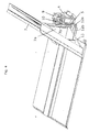
In Fig. 3 ist eine praktische Ausbildungsform des erfindungsgemäßen Bauteils dargestellt.
Die Klemmvorrichtung 4 ist frei auf der Führungsschiene 3 verschiebbar. Ihr
Arbeitszylinder 9 ist eingefahren, die Klemmteile 11, die nachstehend näher beschrieben
werden, sind nicht in Eingriff mit der Führungsschiene 3. Die Klemmvorrichtung 5 ist
dagegen in Klemmstellung. Ihr Arbeitszylinder 10 ist ausgefahren und hat ihre Klemmteile
11 in Eingriff mit der Führungsschiene 3 gebracht.3 shows a practical embodiment of the component according to the invention.
The
Die Klemmvorrichtung 5 ist über eine Patte 13 mit der Stirnwand 7 fest verbunden. Auch
das freie Ende des Kolbens 6b ist mit der Stirnwand 7 über einen Arm 13b der Patte 13 mit
der Stirnwand 7 fest verbunden. Durch eine Öffnung 16 in der Klemmvorrichtung 5 und in
einem Halteteil 7a der Stirnwand 7 kann der Zylinder 6a mittels Verschieben der
Klemmvorrichtung 4 hindurch geschoben werden. Die beiden Klemmvorrichtungen 5 und
4 nähern sich einander, bis ein Kontaktteil 12a die Klemmvorrichtung 4 in Kontakt mit
einem Kontaktarm 12b an der Klemmvorrichtung 5 kommt. Diese Stellung ist in Fig. 4
gezeigt.
Es wird ein Impuls an das Steuergerät 8 geschickt, welches dafür sorgt, daß der
Arbeitszylinder 10 einfährt, die Klemmvorrichtung 5 aus ihrem Eingriff mit der
Führungsschiene 3 löst und die Klemmvorrichtung 4 durch Aussparen ihres
Arbeitszylinders 9 in Klemmstellung mit der Führungsschiene 3 bringt.
Für die konstruktive Ausbildung der Klemmvorrichtungen 4 und 5 kennt man verschiedene
Lösungen.
In Fig. 5 ist eine stirnseitige Ansicht eines Klemmteils 4 oder 5 dargestellt. Ein die
Führungsschiene 3 überbrückendes Tragteil 15 mit einer mittig angeordneten Öffnung 16
für den Durchtritt des Schiebezylinders 6a trägt an seinen beiden unteren Enden 15a, b,
gelenkig angeordnete Hebel 17a,b, die nach oben ragen. Ihre oberen Enden sind gelenkig
bei 18a,b mit dem Ende des Arbeitszylinders 9a, bzw. 10a einerseits und andererseits mit
dem Ende des Kolbens 9b bzw. 10b verbunden. Das gegenüberliegende untere Ende des
Hebels 17a und b ist als Klemmteil 19 ausgebildet, das in den Fig. 7,b und 8 im einzelnen
dargestellt ist.
In Fig. 6 ist die Klemmvorrichtung 4 bzw.5 in perspektivischer Darstellung gezeigt. Man
erkennt, daß das Bauteil 15 zwei in Abständen zueinander angeordnete Platten 15a und 15b
umfaßt, in denen die ebenfalls paarweise ausgebildeten Hebel 17a, b gehalten sind. In den
Fig. 7a und 7b ist eine Ausbildung der Klemmteile 19 dargestellt. Das Klemmteil 19
befindet sich in Fig. 7a in Offenstellung und in Fig. 7b in Schließstellung. Das Klemmteil
19 umfaßt einen walzenförmigen Teil 20 mit einem rechtwinkligen Sektorenausschnitt
20a. Diese Walze 20 ist gelagert in einer dem Durchmesser der Walze 20 angepassten
Schale 21. Beim Verschwenken des Hebelarmes 17a um das Gelenk 15a wird die Walze
20 in Schließstellung mit dem unteren Fortsatz 3a der Führungsschiene 3 hin bewegt. Sie
bewegt sich in der Zeichnung schräg nach oben und dreht sich in der Schale 21 um ihre
Mittelachse, bis sich die Flächen 20a und 20b flächig an die rechtwinkligen Kanten 3a der
Führungsschiene 3 anlegen.
Eine weitere Ausbildung der Klemmteile 19 ist in Fig. 8 stark vergrößert dargestellt.
Hierbei handelt es sich um eine Rasterführung der Klemmteile. Die Führungsschiene 3 ist
bei dieser Ausbildung auf ihrer Unterseite in Form einer Zahnstange 25 ausgebildet. Die
Hebelpaare 17a und 17b sind an ihrem unteren Ende durch Zahnstangen 26 miteinander
verbunden. In Schließstellung pressen sich die Zahnstangen 26 an die Zahnstangen 25 der
Führungsschiene 3 an.The
A pulse is sent to the
Various solutions are known for the design of the
5 shows an end view of a clamping
In Fig. 6, the
A further embodiment of the clamping
Claims (10)
Applications Claiming Priority (2)
| Application Number | Priority Date | Filing Date | Title |
|---|---|---|---|
| DE20207883U DE20207883U1 (en) | 2002-05-22 | 2002-05-22 | Component for sliding trailer |
| DE20207883U | 2002-05-22 |
Publications (2)
| Publication Number | Publication Date |
|---|---|
| EP1364828A2 true EP1364828A2 (en) | 2003-11-26 |
| EP1364828A3 EP1364828A3 (en) | 2005-08-17 |
Family
ID=7971344
Family Applications (1)
| Application Number | Title | Priority Date | Filing Date |
|---|---|---|---|
| EP03010769A Withdrawn EP1364828A3 (en) | 2002-05-22 | 2003-05-14 | Element for a trailer with walking-floor |
Country Status (2)
| Country | Link |
|---|---|
| EP (1) | EP1364828A3 (en) |
| DE (1) | DE20207883U1 (en) |
Cited By (3)
| Publication number | Priority date | Publication date | Assignee | Title |
|---|---|---|---|---|
| EP2497684A1 (en) | 2011-03-10 | 2012-09-12 | Ets JOSKIN S.A. | Transport trailer with unloading by a winding conveyor |
| US9957004B2 (en) | 2014-05-16 | 2018-05-01 | Josef Fliegl, Sr. | Cargo bay construction with a slideable wall and vehicle with such a cargo bay construction |
| WO2023156942A1 (en) * | 2022-02-18 | 2023-08-24 | K-Tec Earthmovers Inc. | Ejector blade and mounting assembly |
Families Citing this family (2)
| Publication number | Priority date | Publication date | Assignee | Title |
|---|---|---|---|---|
| DE202007015652U1 (en) | 2007-11-09 | 2009-03-26 | Komptech Gmbh | Cargo space structure and dolly |
| DE202011100592U1 (en) | 2011-05-12 | 2012-08-13 | Komptech Gmbh | Cargo space of a vehicle, in particular a trolley, cargo space device and a trolley |
Citations (2)
| Publication number | Priority date | Publication date | Assignee | Title |
|---|---|---|---|---|
| FR2689869A1 (en) * | 1992-04-14 | 1993-10-15 | Legras | Device for compacting refuse in semi-trailers - comprises shield moved on rail by slides activated by double acting hydraulic actuator with temporary locking notches on rail |
| EP0992396A2 (en) * | 1998-10-09 | 2000-04-12 | Josef Fliegl | Unloading unit for trailer |
-
2002
- 2002-05-22 DE DE20207883U patent/DE20207883U1/en not_active Expired - Lifetime
-
2003
- 2003-05-14 EP EP03010769A patent/EP1364828A3/en not_active Withdrawn
Patent Citations (2)
| Publication number | Priority date | Publication date | Assignee | Title |
|---|---|---|---|---|
| FR2689869A1 (en) * | 1992-04-14 | 1993-10-15 | Legras | Device for compacting refuse in semi-trailers - comprises shield moved on rail by slides activated by double acting hydraulic actuator with temporary locking notches on rail |
| EP0992396A2 (en) * | 1998-10-09 | 2000-04-12 | Josef Fliegl | Unloading unit for trailer |
Cited By (3)
| Publication number | Priority date | Publication date | Assignee | Title |
|---|---|---|---|---|
| EP2497684A1 (en) | 2011-03-10 | 2012-09-12 | Ets JOSKIN S.A. | Transport trailer with unloading by a winding conveyor |
| US9957004B2 (en) | 2014-05-16 | 2018-05-01 | Josef Fliegl, Sr. | Cargo bay construction with a slideable wall and vehicle with such a cargo bay construction |
| WO2023156942A1 (en) * | 2022-02-18 | 2023-08-24 | K-Tec Earthmovers Inc. | Ejector blade and mounting assembly |
Also Published As
| Publication number | Publication date |
|---|---|
| DE20207883U1 (en) | 2002-09-12 |
| EP1364828A3 (en) | 2005-08-17 |
Similar Documents
| Publication | Publication Date | Title |
|---|---|---|
| DE3300746C2 (en) | ||
| DE102008024051A1 (en) | locking device | |
| DE2750013A1 (en) | TELESCOPIC DEVICE | |
| AT511587B1 (en) | MOVABLE MOUNTING PLATE FOR FURNITURE HINGES | |
| DE102007055047A1 (en) | Locking device for a slide-in frame | |
| AT508071B1 (en) | FURNITURE HINGE | |
| DE2844647A1 (en) | LENGTH ADJUSTMENT FOR A VEHICLE SEAT | |
| EP0941889A2 (en) | Extraction device | |
| EP2054791A1 (en) | Touchpad arrangement | |
| EP1364828A2 (en) | Element for a trailer with walking-floor | |
| DE2749486C2 (en) | ||
| DE2546752C3 (en) | Actuating device for two track markers which can be moved alternately between a first and a second position | |
| DE102007041704A1 (en) | Safety device on forming machines | |
| DE102010015799A1 (en) | Height-adjustable recording of a storage of a bed or Untermatratzenbauteils | |
| EP1377395B1 (en) | Bending machine, especially a bending or folding press, comprising an adjustable lower tool | |
| DE2152569A1 (en) | Hand-operated paper punch | |
| DE2204218B2 (en) | Lock for cabinet with stacked sliding drawers - has bar with stop cams and flat panel independent of drawers | |
| DE2208662A1 (en) | Device for the step-by-step conveyance of production parts, tools and the like, in particular in the case of brush production machines | |
| DE60304742T2 (en) | VOLTAGE DEVICE FOR AN OPENABLE ROOF OF A MOTOR VEHICLE | |
| DE102017100637A1 (en) | Support structure for a chair and seating | |
| DE202008012303U1 (en) | Fitting for pivoting furniture parts | |
| DE2046042A1 (en) | Punching and binding machine | |
| AT377721B (en) | ASSEMBLY DEVICE FOR CONNECTING DRAWER PARTS | |
| DE1654638C (en) | Device for moving shelf units arranged in a row | |
| DE2210705C3 (en) | Drive device for a vehicle sunroof |
Legal Events
| Date | Code | Title | Description |
|---|---|---|---|
| PUAI | Public reference made under article 153(3) epc to a published international application that has entered the european phase |
Free format text: ORIGINAL CODE: 0009012 |
|
| AK | Designated contracting states |
Kind code of ref document: A2 Designated state(s): AT BE BG CH CY CZ DE DK EE ES FI FR GB GR HU IE IT LI LU MC NL PT RO SE SI SK TR |
|
| AX | Request for extension of the european patent |
Extension state: AL LT LV MK |
|
| PUAL | Search report despatched |
Free format text: ORIGINAL CODE: 0009013 |
|
| AK | Designated contracting states |
Kind code of ref document: A3 Designated state(s): AT BE BG CH CY CZ DE DK EE ES FI FR GB GR HU IE IT LI LU MC NL PT RO SE SI SK TR |
|
| AX | Request for extension of the european patent |
Extension state: AL LT LV MK |
|
| RIC1 | Information provided on ipc code assigned before grant |
Ipc: 7B 62D 63/06 B Ipc: 7B 60P 1/00 A |
|
| AKX | Designation fees paid |
Designated state(s): AT BE BG CH CY CZ DE DK EE ES FI FR GB GR HU IE IT LI LU MC NL PT RO SE SI SK TR |
|
| STAA | Information on the status of an ep patent application or granted ep patent |
Free format text: STATUS: THE APPLICATION IS DEEMED TO BE WITHDRAWN |
|
| 18D | Application deemed to be withdrawn |
Effective date: 20060218 |