EP1364622A2 - Elastical system for stabilising the spine - Google Patents
Elastical system for stabilising the spine Download PDFInfo
- Publication number
- EP1364622A2 EP1364622A2 EP03100604A EP03100604A EP1364622A2 EP 1364622 A2 EP1364622 A2 EP 1364622A2 EP 03100604 A EP03100604 A EP 03100604A EP 03100604 A EP03100604 A EP 03100604A EP 1364622 A2 EP1364622 A2 EP 1364622A2
- Authority
- EP
- European Patent Office
- Prior art keywords
- connecting element
- receptacle
- implant according
- spinal implant
- elastic
- Prior art date
- Legal status (The legal status is an assumption and is not a legal conclusion. Google has not performed a legal analysis and makes no representation as to the accuracy of the status listed.)
- Granted
Links
- 230000003019 stabilising effect Effects 0.000 title 1
- 239000007943 implant Substances 0.000 claims abstract description 23
- 239000004033 plastic Substances 0.000 claims description 7
- 229920003023 plastic Polymers 0.000 claims description 7
- 210000000988 bone and bone Anatomy 0.000 claims description 6
- 238000003780 insertion Methods 0.000 claims description 6
- 230000037431 insertion Effects 0.000 claims description 6
- 229920002635 polyurethane Polymers 0.000 claims description 3
- 239000004814 polyurethane Substances 0.000 claims description 3
- 230000005489 elastic deformation Effects 0.000 claims 2
- 239000013013 elastic material Substances 0.000 claims 2
- 238000006073 displacement reaction Methods 0.000 claims 1
- 239000000178 monomer Substances 0.000 claims 1
- 230000006641 stabilisation Effects 0.000 description 7
- 238000011105 stabilization Methods 0.000 description 7
- 230000000087 stabilizing effect Effects 0.000 description 4
- 238000002513 implantation Methods 0.000 description 3
- 239000006096 absorbing agent Substances 0.000 description 2
- 238000005452 bending Methods 0.000 description 2
- 238000005516 engineering process Methods 0.000 description 2
- 238000004519 manufacturing process Methods 0.000 description 2
- 229920000642 polymer Polymers 0.000 description 2
- 230000035939 shock Effects 0.000 description 2
- 125000003118 aryl group Chemical group 0.000 description 1
- 239000000560 biocompatible material Substances 0.000 description 1
- 230000005540 biological transmission Effects 0.000 description 1
- 230000003412 degenerative effect Effects 0.000 description 1
- 230000001419 dependent effect Effects 0.000 description 1
- 230000000694 effects Effects 0.000 description 1
- 230000000642 iatrogenic effect Effects 0.000 description 1
- 239000000463 material Substances 0.000 description 1
- 238000000034 method Methods 0.000 description 1
- 239000004417 polycarbonate Substances 0.000 description 1
- 229920000515 polycarbonate Polymers 0.000 description 1
- 239000000126 substance Substances 0.000 description 1
- 239000004753 textile Substances 0.000 description 1
- 230000007704 transition Effects 0.000 description 1
- 230000003313 weakening effect Effects 0.000 description 1
Images

Classifications
-
- A—HUMAN NECESSITIES
- A61—MEDICAL OR VETERINARY SCIENCE; HYGIENE
- A61B—DIAGNOSIS; SURGERY; IDENTIFICATION
- A61B17/00—Surgical instruments, devices or methods, e.g. tourniquets
- A61B17/56—Surgical instruments or methods for treatment of bones or joints; Devices specially adapted therefor
- A61B17/58—Surgical instruments or methods for treatment of bones or joints; Devices specially adapted therefor for osteosynthesis, e.g. bone plates, screws, setting implements or the like
- A61B17/68—Internal fixation devices, including fasteners and spinal fixators, even if a part thereof projects from the skin
- A61B17/70—Spinal positioners or stabilisers ; Bone stabilisers comprising fluid filler in an implant
- A61B17/7001—Screws or hooks combined with longitudinal elements which do not contact vertebrae
- A61B17/7002—Longitudinal elements, e.g. rods
- A61B17/7019—Longitudinal elements having flexible parts, or parts connected together, such that after implantation the elements can move relative to each other
- A61B17/7026—Longitudinal elements having flexible parts, or parts connected together, such that after implantation the elements can move relative to each other with a part that is flexible due to its form
-
- A—HUMAN NECESSITIES
- A61—MEDICAL OR VETERINARY SCIENCE; HYGIENE
- A61B—DIAGNOSIS; SURGERY; IDENTIFICATION
- A61B17/00—Surgical instruments, devices or methods, e.g. tourniquets
- A61B17/56—Surgical instruments or methods for treatment of bones or joints; Devices specially adapted therefor
- A61B17/58—Surgical instruments or methods for treatment of bones or joints; Devices specially adapted therefor for osteosynthesis, e.g. bone plates, screws, setting implements or the like
- A61B17/68—Internal fixation devices, including fasteners and spinal fixators, even if a part thereof projects from the skin
- A61B17/70—Spinal positioners or stabilisers ; Bone stabilisers comprising fluid filler in an implant
- A61B17/7001—Screws or hooks combined with longitudinal elements which do not contact vertebrae
- A61B17/7002—Longitudinal elements, e.g. rods
- A61B17/7004—Longitudinal elements, e.g. rods with a cross-section which varies along its length
- A61B17/7005—Parts of the longitudinal elements, e.g. their ends, being specially adapted to fit in the screw or hook heads
-
- A—HUMAN NECESSITIES
- A61—MEDICAL OR VETERINARY SCIENCE; HYGIENE
- A61B—DIAGNOSIS; SURGERY; IDENTIFICATION
- A61B17/00—Surgical instruments, devices or methods, e.g. tourniquets
- A61B17/56—Surgical instruments or methods for treatment of bones or joints; Devices specially adapted therefor
- A61B17/58—Surgical instruments or methods for treatment of bones or joints; Devices specially adapted therefor for osteosynthesis, e.g. bone plates, screws, setting implements or the like
- A61B17/68—Internal fixation devices, including fasteners and spinal fixators, even if a part thereof projects from the skin
- A61B17/70—Spinal positioners or stabilisers ; Bone stabilisers comprising fluid filler in an implant
- A61B17/7001—Screws or hooks combined with longitudinal elements which do not contact vertebrae
- A61B17/7002—Longitudinal elements, e.g. rods
- A61B17/701—Longitudinal elements with a non-circular, e.g. rectangular, cross-section
-
- A—HUMAN NECESSITIES
- A61—MEDICAL OR VETERINARY SCIENCE; HYGIENE
- A61B—DIAGNOSIS; SURGERY; IDENTIFICATION
- A61B17/00—Surgical instruments, devices or methods, e.g. tourniquets
- A61B17/56—Surgical instruments or methods for treatment of bones or joints; Devices specially adapted therefor
- A61B17/58—Surgical instruments or methods for treatment of bones or joints; Devices specially adapted therefor for osteosynthesis, e.g. bone plates, screws, setting implements or the like
- A61B17/68—Internal fixation devices, including fasteners and spinal fixators, even if a part thereof projects from the skin
- A61B17/70—Spinal positioners or stabilisers ; Bone stabilisers comprising fluid filler in an implant
- A61B17/7001—Screws or hooks combined with longitudinal elements which do not contact vertebrae
- A61B17/7002—Longitudinal elements, e.g. rods
- A61B17/7019—Longitudinal elements having flexible parts, or parts connected together, such that after implantation the elements can move relative to each other
- A61B17/7031—Longitudinal elements having flexible parts, or parts connected together, such that after implantation the elements can move relative to each other made wholly or partly of flexible material
-
- A—HUMAN NECESSITIES
- A61—MEDICAL OR VETERINARY SCIENCE; HYGIENE
- A61B—DIAGNOSIS; SURGERY; IDENTIFICATION
- A61B17/00—Surgical instruments, devices or methods, e.g. tourniquets
- A61B17/56—Surgical instruments or methods for treatment of bones or joints; Devices specially adapted therefor
- A61B17/58—Surgical instruments or methods for treatment of bones or joints; Devices specially adapted therefor for osteosynthesis, e.g. bone plates, screws, setting implements or the like
- A61B17/68—Internal fixation devices, including fasteners and spinal fixators, even if a part thereof projects from the skin
- A61B17/70—Spinal positioners or stabilisers ; Bone stabilisers comprising fluid filler in an implant
- A61B17/7001—Screws or hooks combined with longitudinal elements which do not contact vertebrae
- A61B17/7032—Screws or hooks with U-shaped head or back through which longitudinal rods pass
-
- A—HUMAN NECESSITIES
- A61—MEDICAL OR VETERINARY SCIENCE; HYGIENE
- A61B—DIAGNOSIS; SURGERY; IDENTIFICATION
- A61B17/00—Surgical instruments, devices or methods, e.g. tourniquets
- A61B17/56—Surgical instruments or methods for treatment of bones or joints; Devices specially adapted therefor
- A61B17/58—Surgical instruments or methods for treatment of bones or joints; Devices specially adapted therefor for osteosynthesis, e.g. bone plates, screws, setting implements or the like
- A61B17/60—Surgical instruments or methods for treatment of bones or joints; Devices specially adapted therefor for osteosynthesis, e.g. bone plates, screws, setting implements or the like for external osteosynthesis, e.g. distractors, contractors
- A61B17/64—Devices extending alongside the bones to be positioned
- A61B17/6466—Devices extending alongside the bones to be positioned with pin-clamps movable along a solid connecting rod
- A61B17/6475—Devices extending alongside the bones to be positioned with pin-clamps movable along a solid connecting rod the connecting rod being threaded
-
- A—HUMAN NECESSITIES
- A61—MEDICAL OR VETERINARY SCIENCE; HYGIENE
- A61B—DIAGNOSIS; SURGERY; IDENTIFICATION
- A61B17/00—Surgical instruments, devices or methods, e.g. tourniquets
- A61B17/56—Surgical instruments or methods for treatment of bones or joints; Devices specially adapted therefor
- A61B17/58—Surgical instruments or methods for treatment of bones or joints; Devices specially adapted therefor for osteosynthesis, e.g. bone plates, screws, setting implements or the like
- A61B17/60—Surgical instruments or methods for treatment of bones or joints; Devices specially adapted therefor for osteosynthesis, e.g. bone plates, screws, setting implements or the like for external osteosynthesis, e.g. distractors, contractors
- A61B17/64—Devices extending alongside the bones to be positioned
- A61B17/6466—Devices extending alongside the bones to be positioned with pin-clamps movable along a solid connecting rod
- A61B17/6483—Devices extending alongside the bones to be positioned with pin-clamps movable along a solid connecting rod the connecting rod having a non-circular section
-
- A—HUMAN NECESSITIES
- A61—MEDICAL OR VETERINARY SCIENCE; HYGIENE
- A61B—DIAGNOSIS; SURGERY; IDENTIFICATION
- A61B17/00—Surgical instruments, devices or methods, e.g. tourniquets
- A61B17/56—Surgical instruments or methods for treatment of bones or joints; Devices specially adapted therefor
- A61B17/58—Surgical instruments or methods for treatment of bones or joints; Devices specially adapted therefor for osteosynthesis, e.g. bone plates, screws, setting implements or the like
- A61B17/68—Internal fixation devices, including fasteners and spinal fixators, even if a part thereof projects from the skin
- A61B17/70—Spinal positioners or stabilisers ; Bone stabilisers comprising fluid filler in an implant
- A61B17/7001—Screws or hooks combined with longitudinal elements which do not contact vertebrae
- A61B17/7002—Longitudinal elements, e.g. rods
- A61B17/7004—Longitudinal elements, e.g. rods with a cross-section which varies along its length
-
- A—HUMAN NECESSITIES
- A61—MEDICAL OR VETERINARY SCIENCE; HYGIENE
- A61B—DIAGNOSIS; SURGERY; IDENTIFICATION
- A61B17/00—Surgical instruments, devices or methods, e.g. tourniquets
- A61B2017/0042—Surgical instruments, devices or methods, e.g. tourniquets with special provisions for gripping
- A61B2017/00429—Surgical instruments, devices or methods, e.g. tourniquets with special provisions for gripping with a roughened portion
Definitions
- the present invention relates to a spinal implant, consisting of a connecting element and several bone screws each with a holder for this connecting element.
- the implant serves that elastic stabilizing a spine of a person with severe Back problems.
- the invention according to patent specification EP 0498 709 B1 wants to stabilize elastically, but has the disadvantage that the System only works in flexion (tension), but not in extension (pressure).
- the Stabilization is created by at least two individual textile loops, that are mutually offset.
- the invention according to patent application WO 93/20771 would also like to connect vertebral bodies with flexible pairs of longitudinal rods.
- this invention has the disadvantages that the longitudinal rods hardly Have kink resistance and thus can hardly transmit compressive forces that the The sticks arranged in pairs are not flexible in all directions can be the same and that the power transmission into the bone screws numerous individual parts must be done.
- the invention according to the patent EP 0516 567 B1 wants Insert the shock absorber between the vertebrae.
- This invention points however, the disadvantages that these shock absorbers are not longitudinally adjustable and the plastic is passed through a narrow area (neck), which is a results in a significant reduction in strength.
- the invention according to US 5,282,863 A wants also stabilize flexibly.
- this invention has the disadvantages that the system is too wide and can only be placed posteriorly if the Pedicles are removed that it can only be used for one segment that, for example, it was not offset by three in a row Screws can be guided that the hole in the connecting element causes a significant weakening and that the oval cross section of the Connecting element only minimal shear rigidity and minimal Has kink resistance in the anterior / posterior direction. Further must go to Attachment of the connecting element to the pedicle screw Closure cap are used, which is disadvantageous during the operation.
- the invention according to the patent specification EP 0669 109 B1 also wants neighboring vertebral segments Stabilize elastically by using a band for tensile forces and a compressive force Plastic pillows are used.
- this invention has the disadvantages on that the system contains an expensive tape, just by any pillow heights a variety of standard pillows can be achieved, the variation of Tension on the tape to biomechanically not reproducible Conditions and the implantation is relatively complex and takes a long time.
- the present invention is therefore based on the objects with both tensile and compressive forces between adjacent vertebral bodies to transmit and through the same connecting element Bone screws, preferably inserted in the pedicle, feasible or to be insertable in the same, which naturally is not on one axis lie.
- the invention accordingly relates to a spinal implant, consisting of a connecting element and several bone screws with one receptacle for this connecting element, which thereby is characterized in that the connecting element about each axis of its Cross section is elastically pliable, such that it through the recordings several screw heads can be inserted or inserted one after the other can, even if they are not on the same axis.
- Connection element consists of an elastically flexible, biocompatible Material, preferably made of a plastic.
- a plastic is a Polymer that can be made up of the same or different building blocks and has the desired mechanical and chemical properties, for example a material based on polyurethane, such as aromatic Polycarbonate polyurethanes (suitable commercial products are, for example: BIONATE ® from Polymer Technology Group, 2810 7th Street, Berkeley, California 94710 USA and ChronoFlex®C from CardioTech International Inc., 78E Olympia Ave., Woburn, MA 01801-2057, USA).
- the proposed connecting element has sufficient bending elasticity around all axes of its cross section, such that its insertion is also possible in recordings of screw heads that are not on an axis, but lie on an arbitrary line, or due to different vertebral body arrangements naturally in different directions are offset.
- the connecting element with the stabilizing effect can one have changed cross-section in the direction of the rod axis, so that there is a position-dependent variable stiffness, which gives him a local gives adapted stabilization effect.
- the Connection element in the form of a hollow rod with varying wall thickness his. If in the text below in connection with the Connecting element is spoken of "original cross section" means this that the cross section is essentially the original, before the Inserting the element present cross section corresponds to what does not excludes the possibility of deviations, e.g. by Squeeze or pretension using the screw head arranged fasteners.
- the recordings integrated into the heads of the bone screws are preferably in a C-shaped shape, in which the elastic Connector fastened by the surgeon in the correct position can be.
- the receptacle can be designed such that it is also elastic to a certain extent. As a result, the Operation allows attachment without additional small implant parts.
- the connecting elements with the receptacles can their surfaces that come into contact with each other during fixation be provided with an interlocking surface structure, such that that if a connecting element is latched into a receptacle, a mutual shifting is no longer possible.
- This surface structure is for example a suitable groove structure with grooves in the transverse direction Connecting element.
- the groove structure can also be a thread structure, which allows screwing in.
- Others can also interlock accessible surface structures are selected, such as a NoppenNertiefungs Modell.
- the Groove structure in the receptacle should be designed so that the Groove structure of the connecting element in an expanded groove structure in the Insertion opening of the receptacle is possible. This can result in a pre-fixation achieved so that the surgeon before latching the connector can check its anatomically correct position in the recording.
- the spinal implant according to the invention is able to degenerative or iatrogenic processes unstable and therefore painful stabilize the spine that has become and thus reduce pain or to avoid entirely.
- the advantage of elastic stabilization is there all in that individual vertebral bodies are no longer stiffened as before must, which in many cases led to consequential damage to neighboring segments Has.
- the particular advantage of the present invention lies in the minor Manufacturing costs and in the simple and safe implantation technology of the System.
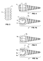
- Fig. 1 with a spine segment with several vertebral bodies left and right pedicle screws and a left and right elastic flexible connecting rod.
- Fig. 1a is a partial view of a spinal segment, but with an alternative recording in the head of the pedicle screws.
- Fig. 2 for example, three pedicle screws with each other offset axes and the inserted elastic pliable Connecting rod.
- Fig. 2a is a partial view of Fig. 2 with an alternative Pedicle screw.
- Fig. 3 is a partial view of an elastically flexible connecting rod with a grooved surface.
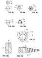
- FIG. 5 and 5a views of a pedicle screw with a grooved Shot in the head, where the groove structure in the slot and the beyond the bevelling is extended.
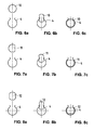
- Fig. 6a the recording with a slot in the screw head and the rod outside the recording.
- Fig. 6b the elastically compressed rod when inserted into the slot with a slot in the screw head.
- Fig. 6c the elastic rod in its original cross-section in the slot.
- Fig. 7a with a slot in the screw head and the rod a flattened side outside the image.
- Fig. 7b the elastic compressed rod with a flattened side when inserted into the With slot in the screw head.
- Fig. 7c the elastic rod with a flattened side in its original cross section rotated in the shot with slit.
- Fig. 8a with a slot in the screw head and the rod two parallel flattened sides outside the image.
- Fig. 8b the elastically compressed rod with two parallel flattened sides when Insert into the slot with a slot in the screw head.
- 8c the elastic rod with two parallel flattened sides in its original Cross-section rotated in the slot with slot.
- Fig. 9a with a slot in the screw head and the rod a cavity in the center outside the recording.
- Fig. 9b the elastic compressed rod with a cavity in the center when inserted into the slot with a slot in the screw head.
- Fig. 9c with the elastic rod a cavity in the center in its original cross section with a Filling piece in the cavity in the slot with slot.
- FIG. 10a the recording with a slot with a clamping device.
- FIG. 10b the elastic rod is clamped in the slot.
- Fig. 11 the recording with slot with a hook device and a hooked wedge.
- Fig. 12a is an elastically flexible connecting rod with grooved, with an inclined surface.
- Fig. 12b the grooved, with the same Inclined recording in the head of the pedicle screw.
- FIG. 1 shows a spinal column segment with three vertebral bodies 1a, 1b, 1c and two intervertebral discs 2a, 2b in between.
- Per vertebral body is a left and right pedicle screw 3, each with a holder 4 used, in which on the left and right an elastically flexible rod-shaped Connection element 5 is attached.
- the connecting elements 5 are in the Recordings 4 stored and serve the flexible stabilization of the vertebral body.
- Figure 1a is a partial view of an analog spine segment with a pedicle screw 3 with an open receptacle 4a for storage a connecting element 5.
- Fig. 2 shows three pedicle screws 3a, 3b, 3c with each other offset axes (6a, 6b, 6c) of their recordings in the head and the inserted elastically flexible rod-shaped connecting element 5.
- Fig. 2a shows a partial view corresponding to Fig. 2, but with a open receptacle 4a for the connecting element 5.
- Fig. 3 shows a partial view of an elastically flexible rod-shaped Connecting element 5 with a grooved surface 7.
- the grooving is used positive engagement in a correspondingly designed receptacle Pedicle screw.
- Fig. 4 shows a side view of a pedicle screw 3a, the head is shown as a partial section (plane a-a in Fig. 4a).
- the head is 4 designed, the one grooved corresponding to the connecting rod Has surface with ribs 8.
- Bevels 9 are provided, which the insertion of a Lighten stabilization element.
- 4a shows the same pedicle screw, however, with respect to its longitudinal axis, which lies in the leaf plane, by 90 ° is rotated.
- the opening of the receptacle 4 with the two is visible here Bevels 9 and a rib 8 of the inner grooved surface.
- 5 is a side view of another embodiment of a Pedicle screw 3, the head of which is also a partial section (along the line b-b 5a) is designed as a modified receptacle 4.
- the Recording has a grooved surface with ribs 8a in the receiving slot, which extend into the chamfer 9a.
- This configuration of the Can be a correspondingly grooved connecting element in front of the Snap into the receptacle to be pre-positioned so that the Surgeon can check the correct position.
- 5a shows the same Pedicle screw, however, with respect to its longitudinal axis, that in the leaf plane is rotated by 90 °.
- the opening of the receptacle 4 with the is visible here two bevels 9a and a rib 8a of the inner grooved surface.
- the extent of the grooved surface on the bevel is visible here 9a.
- Fig. 6a shows schematically in section a receptacle 4 with a slot in Screw head of a pedicle screw and a connecting element 10, the is still outside the recording.
- Fig. 6b shows that elastic compressed connector 10 when inserted into the slot of the Recording 4 in the screw head.
- Fig. 4c shows the elastic in section Connecting element 10 in its original cross section in the Mount 4 with slot in the screw head. Here he is using the grooved surfaces are positively anchored.
- Fig. 7a shows the section as the receptacle 4 with a slot designed screw head and the rod-shaped connecting element 11 with a flattened side outside of the receptacle 4.
- Fig. 7b shows that elastically compressed connecting element 11 with a flattened Side when inserted into the slot with a slot in the screw head.
- Fig. 7c shows the elastic connecting element 11 with a flattened side again in its original cross-section in the receptacle 4 with slot in Screw head inserted, rotated by 90 ° and with the help of the grooved Anchored surfaces positively.
- FIG. 8a shows in section the receptacle 4 with a slot in the screw head and the connecting element 12 with two parallel flattened sides outside the receptacle 4.
- Fig. 8b shows the elastically compressed Connecting element with two parallel flattened sides 12 when inserted into the receptacle 4 with a slot in the screw head.
- 8c shows the elastic Connecting element 12 with two parallel flattened sides in turn its original cross-section in the receptacle 4 with a slot in the screw head introduced, rotated by 90 ° and using the grooved surfaces anchored positively.
- FIG. 9a shows in section the receptacle 4 with a slot in the screw head and a connecting element 13 with a cavity 14 in the center outside the receptacle 4.
- Fig. 9b shows the elastically compressed Connecting element 13 with a cavity 14 in the center when inserted into the receptacle 4 with a slot in the screw head.
- the cavity 14 in the center of the connecting element 13 facilitates the elastic Squeeze the connector for easier insertion.
- FIG. 9c shows the elastic connecting element 13 with a cavity 14 in Center again in its original cross-section in the recording 4 with Slit introduced in the screw head, but now with a cavity filling (optional) pin 15 and using the grooved Surfaces that are in the receptacle 4 and on the connecting element 13 are firmly anchored.
- FIG. 10a shows in section a further embodiment of a Recording 16 with a slot in the screw head provided with a Clamping device 17.
- Fig. 10b shows the receptacle 16 with a slot in Screw head, an inserted connector 5 in his clamped cross section and with the clamping device 17 contracted.
- FIG. 11 shows a further embodiment of a receptacle 18 with Slot in the screw head provided with a hook device 19 and pre-tensioned wedge 20 to hold the Connection element 5.
- FIG. 12a shows a partial view of an elastically flexible rod-shaped connecting element 5a with grooved, with a slope 21st provided surface and Fig. 12b shows the grooved, with the same slope 22 provided in the head of the pedicle screw 3.
- the grooves with Incline cause the rod to be like a screw and the holder in the Screw head behave like a nut, allowing the rod to turn around the longitudinal axis is screwed into the screw heads and carried out can.
Landscapes
- Health & Medical Sciences (AREA)
- Orthopedic Medicine & Surgery (AREA)
- Life Sciences & Earth Sciences (AREA)
- Neurology (AREA)
- Surgery (AREA)
- Heart & Thoracic Surgery (AREA)
- General Health & Medical Sciences (AREA)
- Biomedical Technology (AREA)
- Nuclear Medicine, Radiotherapy & Molecular Imaging (AREA)
- Medical Informatics (AREA)
- Molecular Biology (AREA)
- Animal Behavior & Ethology (AREA)
- Engineering & Computer Science (AREA)
- Public Health (AREA)
- Veterinary Medicine (AREA)
- Surgical Instruments (AREA)
- Prostheses (AREA)
- Orthopedics, Nursing, And Contraception (AREA)
- Vehicle Body Suspensions (AREA)
Abstract
Description
Die vorliegende Erfindung betrifft ein Wirbelsäulenimplantat, bestehend aus einem Verbindungselement und mehreren Knochenschrauben mit je einer Aufnahme für dieses Verbindungselement. Das Implantat dient dem elastischen Stabilisieren einer Wirbelsäule einer Person mit schweren Rückenbeschwerden.The present invention relates to a spinal implant, consisting of a connecting element and several bone screws each with a holder for this connecting element. The implant serves that elastic stabilizing a spine of a person with severe Back problems.
Der Stand der Technik liegt heute noch meistens in Stabilisiersystemen, welche ein knöchernes Verwachsen (Versteifung) betroffener Wirbelkörper zum Ziele haben. Elastische Systeme, welche die Wirbelsäulensegmente lediglich stützen und stabilisieren, nicht aber versteifen sollen, sind erst vereinzelt erschienen. Oft sind diese neueren elastischen Systeme noch mit einem erheblichen Implantationsaufwand verbunden. Aus Gründen der Herstellkosten, der Operationszeit und der Sicherheit in der Handhabung sollen künftige Wirbelsäulenstabilisiersysteme so einfach wie möglich sein.The state of the art is still mostly in today Stabilizing systems that prevent bony growth (stiffening) target the affected vertebral body. Elastic systems, which the Only support and stabilize spine segments, but not stiffen them have only appeared occasionally. Often these are newer elastic ones Systems still involve a considerable amount of implantation. Out Because of the manufacturing costs, the operating time and the safety in the Future spinal stabilization systems should be as easy as handling to be possible.
Die Vorteile von elastischen Stabilisierungen werden zunehmend bekannter, vor allem bei jungen Patienten, so dass verschiedene Erfinder solche Systeme entwickelt und offengelegt haben. Diese Erfindungen bergen aber Nachteile in sich, welche anhand folgender Beispiele erläutert werden.The advantages of elastic stabilization are increasing more well-known, especially among young patients, so that different inventors have developed and disclosed such systems. These inventions hold but disadvantages in themselves, which are explained using the following examples.
Die Erfindung gemäss der Patentschrift EP 0498 709 B1 (Graf) möchte zwar elastisch stabilisieren, weist jedoch den Nachteil auf, dass das System nur in Flexion (Zug), nicht aber in Extension (Druck) wirkt. Die Stabilisierung wird durch mindestens zwei einzelne textile Schlingen erzeugt, die gegenseitig versetzt sind.The invention according to patent specification EP 0498 709 B1 (Graf) wants to stabilize elastically, but has the disadvantage that the System only works in flexion (tension), but not in extension (pressure). The Stabilization is created by at least two individual textile loops, that are mutually offset.
Die Erfindung gemäss der Patentanmeldung WO 93/20771 (Mazel) möchte Wirbelkörper auch mit flexiblen paarweisen Längsstäbchen verbinden. Diese Erfindung weist jedoch die Nachteile auf, dass die Längsstäbchen kaum Knickfestigkeit haben und damit kaum Druckkräfte übertragen können, dass die Biegsamkeit der paarweise angeordneten Stäbchen nicht in alle Richtungen gleich sein kann und dass die Kraftübertragung in die Knochenschrauben mit zahlreichen Einzelteilen erfolgen muss.The invention according to patent application WO 93/20771 (Mazel) would also like to connect vertebral bodies with flexible pairs of longitudinal rods. However, this invention has the disadvantages that the longitudinal rods hardly Have kink resistance and thus can hardly transmit compressive forces that the The sticks arranged in pairs are not flexible in all directions can be the same and that the power transmission into the bone screws numerous individual parts must be done.
Die Erfindung gemäss der Patentschrift EP 0516 567 B1 (Navas) will Stossdämpfer zwischen die Wirbelkörper einbringen. Diese Erfindung weist jedoch die Nachteile auf, dass diese Stossdämpfer nicht längsverstellbar sind und der Kunststoff durch eine enge Stelle (Hals) geführt wird, was eine erhebliche Verminderung der Festigkeit zur Folge hat.The invention according to the patent EP 0516 567 B1 (Navas) wants Insert the shock absorber between the vertebrae. This invention points however, the disadvantages that these shock absorbers are not longitudinally adjustable and the plastic is passed through a narrow area (neck), which is a results in a significant reduction in strength.
Die Erfindung gemäss der Patentschrift US 5,282,863 A (Burton) will auch flexibel stabilisieren. Diese Erfindung weist jedoch die Nachteile auf, dass das System zu breit ist und posterior nur gesetzt werden kann, wenn die Pedikel entfernt sind, dass es nur für ein Segment verwendet werden kann, dass es zum Beispiel nicht durch drei hintereinander liegende und versetzte Schrauben geführt werden kann, dass die Bohrung im Verbindungselement eine erhebliche Schwächung zur Folge hat und dass der ovale Querschnitt des Verbindungselementes nur eine minimale Schubsteifigkeit und minimale Knickfestigkeit in anteriorer / posteriorer Richtung aufweist. Weiter muss zur Befestigung des Verbindungselements an der Pedikelschraube eine Verschlusskappe verwendet werden, was bei der Operation nachteilig ist.The invention according to US 5,282,863 A (Burton) wants also stabilize flexibly. However, this invention has the disadvantages that the system is too wide and can only be placed posteriorly if the Pedicles are removed that it can only be used for one segment that, for example, it was not offset by three in a row Screws can be guided that the hole in the connecting element causes a significant weakening and that the oval cross section of the Connecting element only minimal shear rigidity and minimal Has kink resistance in the anterior / posterior direction. Further must go to Attachment of the connecting element to the pedicle screw Closure cap are used, which is disadvantageous during the operation.
Die Erfindung gemäss der Patentanmeldung EP 0 667 127 A1 (Sanders) will eine gewisse Elastizität durch eine metallische Verbindung erreichen, indem die Gestaltung des Verbindungsteiles lokale Biegung zulässt. Diese Erfindung weist jedoch den Nachteil auf, dass die Verbindungsteile nicht längsverstellbar sind und nicht mehrsegmental eingesetzt werden können.The invention according to patent application EP 0 667 127 A1 (Sanders) wants a certain elasticity through a metallic connection achieve by allowing the design of the connecting part to allow local bending. However, this invention has the disadvantage that the connecting parts are not are longitudinally adjustable and can no longer be used in multiple segments.
Die Erfindung gemäss der Patentschrift EP 0669 109 B1 (Baumgartner/Freudiger/Dubois) will benachbarte Wirbelsegmente ebenfalls elastisch stabilisieren, indem für Zugkräfte ein Band und für Druckkräfte ein Kunststoffkissen eingesetzt werden. Diese Erfindung weist jedoch die Nachteile auf, dass das System ein teures Band enthält, beliebige Kissenhöhen nur durch eine Mehrzahl von Standard-Kissen erreicht werden kann, die Variation der Vorspannung auf das Band zu biomechanisch nicht reproduzierbaren Verhältnissen führt und die Implantation relativ aufwendig ist und lange dauert. The invention according to the patent specification EP 0669 109 B1 (Baumgartner / Freudiger / Dubois) also wants neighboring vertebral segments Stabilize elastically by using a band for tensile forces and a compressive force Plastic pillows are used. However, this invention has the disadvantages on that the system contains an expensive tape, just by any pillow heights a variety of standard pillows can be achieved, the variation of Tension on the tape to biomechanically not reproducible Conditions and the implantation is relatively complex and takes a long time.
Der vorliegenden Erfindung liegen demnach die Aufgaben zugrunde, sowohl Zug- wie auch Druckkräfte zwischen benachbarten Wirbelkörpern mit ein und demselben Verbindungselement zu übertragen und durch Knochenschrauben, vorzugsweise in die Pedikel eingesetzt, durchführbar oder in dieselben einlegbar zu sein, welche naturgemäss nicht auf einer Achse liegen.The present invention is therefore based on the objects with both tensile and compressive forces between adjacent vertebral bodies to transmit and through the same connecting element Bone screws, preferably inserted in the pedicle, feasible or to be insertable in the same, which naturally is not on one axis lie.
Die Lösung dieser Aufgabe zeichnet sich dadurch aus, dass ein elastisches Verbindungselement verwendet wird, welches aufgrund der örtlichen, maximal zulässigen, Querschnitten ausreichend Schub-, Zug-, Druckund Knickfestigkeit erzielt, um die zu erwartenden Kräfte dauerhaft und sicher zu übertragen.The solution to this problem is characterized by the fact that a elastic connecting element is used, which due to the local, maximum permissible, cross sections sufficient thrust, tension, pressure and Kink resistance achieved to ensure the expected forces are permanent and safe transferred to.
Gegenstand der Erfindung ist demzufolge ein Wirbelsäulenimplantat, bestehend aus einem Verbindungselement und mehreren Knochenschrauben mit je einer Aufnahme für dieses Verbindungselement, das dadurch gekennzeichnet ist, dass das Verbindungselement um jede Achse seines Querschnittes elastisch biegsam ist, derart, dass es durch die Aufnahmen mehrerer Schraubenköpfe hintereinander durchgeführt oder eingelegt werden kann, auch wenn sich diese nicht auf ein und derselben Achse befinden.The invention accordingly relates to a spinal implant, consisting of a connecting element and several bone screws with one receptacle for this connecting element, which thereby is characterized in that the connecting element about each axis of its Cross section is elastically pliable, such that it through the recordings several screw heads can be inserted or inserted one after the other can, even if they are not on the same axis.
Das um jede Achse seines Querschnittes elastisch biegsame Verbindungselement besteht aus einem elastisch biegsamen biokompatiblen Material, vorzugsweise aus einem Kunststoff. Ein solcher Kunststoff ist ein Polymer, das aus gleichen oder verschieden Bausteinen aufgebaut sein kann und die gewünschten mechanischen und chemischen Eigenschaften besitzt, zum Beispiel ein Material auf Basis von Polyurethan, wie aromatische Polycarbonat-Polyurethane (geeignete Handelsprodukte sind beispielsweise: BIONATE ® von Polymer Technology Group, 2810 7th Street, Berkeley, California 94710 USA und ChronoFlex®C von CardioTech International Inc., 78E Olympia Ave., Woburn, MA 01801-2057, USA). Das erfindungsgemäss vorgeschlagene Verbindungselement besitzt eine ausreichende Biegeelastizität um alle Achsen seines Querschnittes, derart, dass das Einführen desselben auch in Aufnahmen von Schraubenköpfen ermöglicht wird, welche nicht auf einer Achse, sondern auf einer willkürlich verlaufenden Linie liegen, oder aufgrund unterschiedlicher Wirbelkörperanordnungen naturgemäss in verschiedene Richtungen versetzt sind.That is elastically flexible around each axis of its cross section Connection element consists of an elastically flexible, biocompatible Material, preferably made of a plastic. Such a plastic is a Polymer that can be made up of the same or different building blocks and has the desired mechanical and chemical properties, for example a material based on polyurethane, such as aromatic Polycarbonate polyurethanes (suitable commercial products are, for example: BIONATE ® from Polymer Technology Group, 2810 7th Street, Berkeley, California 94710 USA and ChronoFlex®C from CardioTech International Inc., 78E Olympia Ave., Woburn, MA 01801-2057, USA). According to the invention The proposed connecting element has sufficient bending elasticity around all axes of its cross section, such that its insertion is also possible in recordings of screw heads that are not on an axis, but lie on an arbitrary line, or due to different vertebral body arrangements naturally in different directions are offset.
Das Verbindungselement mit dem stabilisierenden Effekt kann einen in Richtung der Stabachse veränderten Querschnitt aufweisen, damit es eine positionsabhängige veränderliche Steifigkeit aufweist, was ihm einen lokal angepassten Stabilisierungseffekt verleiht. Dadurch kann der Stabilisierungseffekt benachbarter Wirbelkörper eingestellt werden, bis hin zur lokalen Versteifung mit graduellen Übergängen. Hierzu kann das Verbindungselement die Form eines hohlen Stabes mit variierter Wandstärke sein. Wenn im nachstehenden Text im Zusammenhang mit dem Verbindungselement von "originalem Querschnitt" gesprochen wird, bedeutet dies, dass der Querschnitt im Wesentlichen dem ursprünglichen, vor dem Einsetzen des Elementes vorgelegenen Querschnitt entspricht, was nicht ausschliesst, dass Abweichungen vorkommen können, z.B. durch Zusammendrücken bzw. durch Vorspannung durch das am Schraubenkopf angeordnete Befestigungsmittel.The connecting element with the stabilizing effect can one have changed cross-section in the direction of the rod axis, so that there is a position-dependent variable stiffness, which gives him a local gives adapted stabilization effect. This allows the Stabilizing effect of adjacent vertebral bodies can be set up to local stiffening with gradual transitions. For this, the Connection element in the form of a hollow rod with varying wall thickness his. If in the text below in connection with the Connecting element is spoken of "original cross section" means this that the cross section is essentially the original, before the Inserting the element present cross section corresponds to what does not excludes the possibility of deviations, e.g. by Squeeze or pretension using the screw head arranged fasteners.
Die Aufnahmen, die in die Köpfe der Knochenschrauben integriert sind, besitzen vorzugsweise eine C-förmige Form, in welche das elastische Verbindungselement durch den Chirurgen in der korrekten Position eingeklinkt werden kann. Hierzu kann die Aufnahme derart ausgestaltet sein, dass sie ebenfalls in einem bestimmten Ausmass elastisch ist. Dadurch wird bei der Operation eine Befestigung ohne zusätzliche kleine Implantatteile ermöglicht.The recordings integrated into the heads of the bone screws are preferably in a C-shaped shape, in which the elastic Connector fastened by the surgeon in the correct position can be. For this purpose, the receptacle can be designed such that it is also elastic to a certain extent. As a result, the Operation allows attachment without additional small implant parts.
Zwecks Fixierung der Verbindungselemente mit den Aufnahmen können ihre Oberflächen, die bei der Fixierung miteinander in Kontakt kommen mit einer ineinander eingreifbaren Oberflächenstruktur versehen sein, derart, dass wenn ein Verbindungselement in eine Aufnahme eingeklinkt ist, ein gegenseitiges Verschieben nicht mehr möglich ist. Diese Oberflächenstruktur ist beispielsweise eine geeignete Rillenstruktur mit Rillen in Querrichtung zum Verbindungselement. Die Rillenstruktur kann auch eine Gewindestruktur sein, die ein Einschrauben ermöglicht. Es können auch andere ineinander eingreifbare Oberflächenstrukturen ausgewählt werden, wie beispielsweise eine NoppenNertiefungsstruktur. Bei der Verwendung einer Rillenstruktur in Querrichtung zur Längsachse des Verbindungselementes, kann die Rillenstruktur in der Aufnahme so ausgestaltet sein, dass ein Eingreifen der Rillenstruktur des Verbindungselementes in eine erweiterte Rillenstruktur in der Einschuböffnung der Aufnahme möglich ist. Dadurch kann eine Vor-Fixierung erzielt werden, damit der Chirurg vor dem Einklinken des Verbindungselements in die Aufnahme seine anatomisch korrekte Position kontrollieren kann.For the purpose of fixing the connecting elements with the receptacles can their surfaces that come into contact with each other during fixation be provided with an interlocking surface structure, such that that if a connecting element is latched into a receptacle, a mutual shifting is no longer possible. This surface structure is for example a suitable groove structure with grooves in the transverse direction Connecting element. The groove structure can also be a thread structure, which allows screwing in. Others can also interlock accessible surface structures are selected, such as a NoppenNertiefungsstruktur. When using a groove structure in Transverse direction to the longitudinal axis of the connecting element, the Groove structure in the receptacle should be designed so that the Groove structure of the connecting element in an expanded groove structure in the Insertion opening of the receptacle is possible. This can result in a pre-fixation achieved so that the surgeon before latching the connector can check its anatomically correct position in the recording.
Das erfindungsgemässe Wirbelsäulenimplantat ist in der Lage, durch degenerative oder iatrogene Vorgänge instabil und dadurch schmerzhaft gewordene Wirbelsäulen zu stabilisieren und damit Schmerzen zu verringern oder ganz zu vermeiden. Der Vorteil einer elastischen Stabilisierung liegt vor allem darin, dass einzelne Wirbelkörper nicht mehr wie früher versteift werden müssen, was in vielen Fallen zu Folgeschäden an Nachbarsegmenten geführt hat. Der besondere Vorteil der vorliegenden Erfindung liegt in den geringen Herstellkosten sowie in der einfachen und sicheren Implantationstechnik des Systems.The spinal implant according to the invention is able to degenerative or iatrogenic processes unstable and therefore painful stabilize the spine that has become and thus reduce pain or to avoid entirely. The advantage of elastic stabilization is there all in that individual vertebral bodies are no longer stiffened as before must, which in many cases led to consequential damage to neighboring segments Has. The particular advantage of the present invention lies in the minor Manufacturing costs and in the simple and safe implantation technology of the System.
Die nachstehende Figurenliste gibt einen Überblick über die beiliegenden Zeichnungen.The figure list below gives an overview of the enclosed drawings.
Es zeigen schematisch:They show schematically:
Fig. 1 ein Wirbelsäulensegment mit mehreren Wirbelkörpern mit linken und rechten Pedikelschrauben und einem linken und rechten elastisch biegsamen Verbindungsstab.Fig. 1 with a spine segment with several vertebral bodies left and right pedicle screws and a left and right elastic flexible connecting rod.
Fig. 1a eine Teilansicht eines Wirbelsäulensegmentes, jedoch mit einer alternativen Aufnahme im Kopf der Pedikelschrauben.Fig. 1a is a partial view of a spinal segment, but with an alternative recording in the head of the pedicle screws.
Fig. 2 beispielsweise drei Pedikelschrauben mit gegeneinander versetzten Achsen und dem eingeführten elastisch biegsamen Verbindungsstab.Fig. 2, for example, three pedicle screws with each other offset axes and the inserted elastic pliable Connecting rod.
Fig. 2a eine Teilansicht von Fig. 2 mit einer alternativen Pedikelschraube. Fig. 2a is a partial view of Fig. 2 with an alternative Pedicle screw.
Fig. 3 eine Teilansicht eines elastisch biegsamer Verbindungsstab mit gerillter Oberfläche.Fig. 3 is a partial view of an elastically flexible connecting rod with a grooved surface.
Fig. 4 und 4a Ansichten einer Pedikelschraube mit einer gerillten Aufnahme im Kopf.4 and 4a views of a pedicle screw with a grooved Shot in the head.
Fig. 5 und 5a Ansichten einer Pedikelschraube mit einer gerillten Aufnahme im Kopf, wo die Rillenstruktur in den Aufnahmeschlitz und die darüber hinausragende Anschrägung ausgedehnt ist.5 and 5a views of a pedicle screw with a grooved Shot in the head, where the groove structure in the slot and the beyond the bevelling is extended.
Fig. 6a die Aufnahme mit Schlitz im Schraubenkopf und den Stab ausserhalb der Aufnahme. Fig. 6b den elastisch zusammengedrückten Stab beim Einführen in die Aufnahme mit Schlitz im Schraubenkopf. Fig. 6c den elastischen Stab in seinem originalen Querschnitt in der Aufnahme mit Schlitz.Fig. 6a, the recording with a slot in the screw head and the rod outside the recording. Fig. 6b the elastically compressed rod when inserted into the slot with a slot in the screw head. Fig. 6c the elastic rod in its original cross-section in the slot.
Fig. 7a die Aufnahme mit Schlitz im Schraubenkopf und den Stab mit einer abgeflachten Seite ausserhalb der Aufnahme. Fig. 7b den elastisch zusammengedrückten Stab mit einer abgeflachten Seite beim Einführen in die Aufnahme mit Schlitz im Schraubenkopf. Fig. 7c den elastischen Stab mit einer abgeflachten Seite in seinem originalen Querschnitt gedreht in der Aufnahme mit Schlitz.Fig. 7a with a slot in the screw head and the rod a flattened side outside the image. Fig. 7b the elastic compressed rod with a flattened side when inserted into the With slot in the screw head. Fig. 7c the elastic rod with a flattened side in its original cross section rotated in the shot with slit.
Fig. 8a die Aufnahme mit Schlitz im Schraubenkopf und den Stab mit zwei parallel abgeflachten Seiten ausserhalb der Aufnahme. Fig. 8b den elastisch zusammengedrückten Stab mit zwei parallel abgeflachten Seiten beim Einführen in die Aufnahme mit Schlitz im Schraubenkopf. Fig. 8c den elastischen Stab mit zwei parallel abgeflachten Seiten in seinem originalen Querschnitt gedreht in der Aufnahme mit Schlitz.Fig. 8a with a slot in the screw head and the rod two parallel flattened sides outside the image. Fig. 8b the elastically compressed rod with two parallel flattened sides when Insert into the slot with a slot in the screw head. 8c the elastic rod with two parallel flattened sides in its original Cross-section rotated in the slot with slot.
Fig. 9a die Aufnahme mit Schlitz im Schraubenkopf und den Stab mit einem Hohlraum im Zentrum ausserhalb der Aufnahme. Fig. 9b den elastisch zusammengedrückten Stab mit einem Hohlraum im Zentrum beim Einführen in die Aufnahme mit Schlitz im Schraubenkopf. Fig. 9c den elastischen Stab mit einem Hohlraum im Zentrum in seinem originalen Querschnitt mit einem Füllstück im Hohlraum in der Aufnahme mit Schlitz. Fig. 9a with a slot in the screw head and the rod a cavity in the center outside the recording. Fig. 9b the elastic compressed rod with a cavity in the center when inserted into the slot with a slot in the screw head. Fig. 9c with the elastic rod a cavity in the center in its original cross section with a Filling piece in the cavity in the slot with slot.
Fig. 10a die Aufnahme mit Schlitz mit einer Klemmvorrichtung. Fig. 10b den elastischen Stab geklemmt in der Aufnahme mit Schlitz.Fig. 10a, the recording with a slot with a clamping device. FIG. 10b the elastic rod is clamped in the slot.
Fig. 11 die Aufnahme mit Schlitz mit einer Hakenvorrichtung und einem eingehakten Keil.Fig. 11, the recording with slot with a hook device and a hooked wedge.
Fig. 12a ein elastisch biegsamer Verbindungsstab mit gerillter, mit einer Steigung versehenen Oberfläche. Fig. 12b die gerillte, mit derselben Steigung versehenen Aufnahme im Kopf der Pedikelschraube.Fig. 12a is an elastically flexible connecting rod with grooved, with an inclined surface. Fig. 12b the grooved, with the same Inclined recording in the head of the pedicle screw.
Im Folgenden wird die vorliegende Erfindung anhand der beiliegenden Zeichnungen, welche lediglich Ausführungsbeispiele darstellen, näher erläutert.In the following, the present invention is based on the accompanying drawings, which only represent exemplary embodiments, explained in more detail.
Fig. 1 stellt ein Wirbelsäulensegment dar, mit drei Wirbelkörpern 1a,
1b, 1c und zwei dazwischen liegenden Bandscheiben 2a, 2b. Pro Wirbelkörper
ist jeweils links und rechts eine Pedikelschraube 3 mit je einer Aufnahme 4
eingesetzt, in welche links und rechts je ein elastisch biegsames stabförmiges
Verbindungselement 5 befestigt ist. Die Verbindungselemente 5 sind in den
Aufnahmen 4 gelagert und dienen der flexiblen Stabilisierung der Wirbelkörper.1 shows a spinal column segment with three
Fig. 1a ist eine Teilansicht eines analogen Wirbelsäulensegmentes
mit einer Pedikelschraube 3 mit einer offenen Aufnahme 4a für die Lagerung
eines Verbindungselementes 5.Figure 1a is a partial view of an analog spine segment
with a
Fig. 2 zeigt drei Pedikelschrauben 3a, 3b, 3c mit gegeneinander
versetzten Achsen (6a, 6b, 6c) ihrer Aufnahmen im Kopf und dem eingeführten
elastisch biegsamen stabförmigen Verbindungselement 5.Fig. 2 shows three
Fig. 2a zeigt eine Teilansicht entsprechend Fig. 2, jedoch mit einer
offenen Aufnahme 4a für das Verbindungselement 5.Fig. 2a shows a partial view corresponding to Fig. 2, but with a
Fig. 3 zeigt eine Teilansicht eines elastisch biegsamen stabförmigen
Verbindungselements 5 mit gerillter Oberfläche 7. Die Rillung dient dem
formschlüssigen Eingreifen in eine entsprechend ausgestaltete Aufnahme einer
Pedikelschraube.Fig. 3 shows a partial view of an elastically flexible rod-shaped
Fig. 4 zeigt eine Seitenansicht einer Pedikelschraube 3a, deren Kopf
als Teilschnitt (Ebene a-a in Fig. 4a) dargestellt ist. Der Kopf ist als Aufnahme 4
ausgestaltet, die eine entsprechend dem Verbindungsstab innere gerillte
Oberfläche mit Rippen 8 besitzt. In der Aufnahmeöffnung sind beidseitig
Anschrägungen 9 vorgesehen, welche das Einsetzen eines
Stabilisierungselementes erleichtern. Fig. 4a zeigt die gleiche Pedikelschraube,
die jedoch bezüglich ihrer Längsachse, die in der Blattebene liegt, um 90°
gedreht ist. Sichtbar ist hier die Öffnung der Aufnahme 4 mit den beiden
Anschrägungen 9 und einer Rippe 8 der inneren gerillten Oberfläche.Fig. 4 shows a side view of a
Fig. 5 ist eine Seitenansicht einer weiteren Ausführungsform einer
Pedikelschraube 3, deren Kopf, der auch als Teilschnitt (entlang der Linie b-b
von Fig. 5a) dargestellt ist, als modifizierte Aufnahme 4 ausgestaltet ist. Die
Aufnahme besitzt im Aufnahmeschlitz eine gerillte Oberfläche mit Rippen 8a,
die sich bis in die Anschrägung 9a ausdehnen. Durch diese Ausgestaltung der
Aufnahme kann ein entsprechend gerilltes Verbindungselement vor dem
Einrasten in die Aufnahme verschiebungsfrei vorpositioniert werden, damit der
Chirurg die korrekte Position kontrollieren kann. Fig. 5a zeigt die gleiche
Pedikelschraube, die jedoch bezüglich ihrer Längsachse, die in der Blattebene
liegt, um 90° gedreht ist. Sichtbar ist hier die Öffnung der Aufnahme 4 mit den
beiden Anschrägungen 9a und einer Rippe 8a der inneren gerillten Oberfläche.
Sichtbar ist hier die Ausdehnung der gerillten Oberfläche auf die Anschrägung
9a.5 is a side view of another embodiment of a
Fig. 6a zeigt schematisch im Schnitt eine Aufnahme 4 mit Schlitz im
Schraubenkopf einer Pedikelschraube und ein Verbindungselement 10, das
sich noch ausserhalb der Aufnahme befindet. Fig. 6b zeigt das elastisch
zusammengedrückte Verbindungselement 10 beim Einführen in den Schlitz der
Aufnahme 4 im Schraubenkopf. Fig. 4c zeigt im Schnitt das elastischen
Verbindungselement 10 wiederum in seinem originalen Querschnitt in die
Aufnahme 4 mit Schlitz im Schraubenkopf eingebracht. Hier wird er mit Hilfe der
gerillten Oberflächen formschlüssig verankert. Fig. 6a shows schematically in section a
Fig. 7a zeigt im Schnitt den als Aufnahme 4 mit Schlitz
ausgestalteten Schraubenkopf und das stabförmige Verbindungselement 11 mit
einer abgeflachten Seite noch ausserhalb der Aufnahme 4. Fig. 7b zeigt das
elastisch zusammengedrückte Verbindungselement 11 mit einer abgeflachten
Seite beim Einführen in die Aufnahme mit Schlitz im Schraubenkopf. Fig. 7c
zeigt das elastische Verbindungselement 11 mit einer abgeflachten Seite
wiederum in seinem originalen Querschnitt in die Aufnahme 4 mit Schlitz im
Schraubenkopf eingebracht, um 90° gedreht und mit Hilfe der gerillten
Oberflächen formschlüssig verankert.Fig. 7a shows the section as the
Fig. 8a zeigt im Schnitt die Aufnahme 4 mit Schlitz im Schraubenkopf
und das Verbindungselement 12 mit zwei parallel abgeflachten Seiten noch
ausserhalb der Aufnahme 4. Fig. 8b zeigt das elastisch zusammen gedrückte
Verbindungselement mit zwei parallel abgeflachten Seiten 12 beim Einführen in
die Aufnahme 4 mit Schlitz im Schraubenkopf. Fig. 8c zeigt das elastische
Verbindungselement 12 mit zwei parallel abgeflachten Seiten wiederum in
seinem originalen Querschnitt in die Aufnahme 4 mit Schlitz im Schraubenkopf
eingebracht, um 90° gedreht und mit Hilfe der gerillten Oberflächen
formschlüssig verankert.8a shows in section the
Fig. 9a zeigt im Schnitt die Aufnahme 4 mit Schlitz im Schraubenkopf
und ein Verbindungselement 13 mit einem Hohlraum 14 im Zentrum noch
ausserhalb der Aufnahme 4. Fig. 9b zeigt das elastisch zusammengedrückte
Verbindungselement 13 mit einem Hohlraum 14 im Zentrum beim Einführen in
die Aufnahme 4 mit Schlitz im Schraubenkopf. Der Hohlraum 14 im Zentrum
des Verbindungselementes 13 erleichtert hierbei das elastische
Zusammendrücken des Verbindungselementes zum einfacheren Einführen. Fig.
9c zeigt das elastische Verbindungselement 13 mit einem Hohlraum 14 im
Zentrum wiederum in seinem originalen Querschnitt in die Aufnahme 4 mit
Schlitz im Schraubenkopf eingebracht, aber nunmehr mit einem den Hohlraum
ausfüllenden (optionalen) Zapfen 15 versehen und mit Hilfe der gerillten
Oberflächen, die sich in der Aufnahme 4 und auf dem Verbindungselement 13
befinden, formschlüssig verankert. 9a shows in section the
Fig. 10a zeigt im Schnitt eine weitere Ausführungsform einer
Aufnahme 16 mit Schlitz im Schraubenkopf versehen mit einer
Klemmvorrichtung 17. Fig. 10b zeigt die Aufnahme 16 mit Schlitz im
Schraubenkopf, einem eingeführten Verbindungselement 5 in seinem
geklemmten Querschnitt und mit zusammengezogener Klemmvorrichtung 17.10a shows in section a further embodiment of a
Fig. 11 zeigt eine weitere Ausführungsform einer Aufnahme18 mit
Schlitz im Schraubenkopf versehen mit einer Hakenvorrichtung 19 und einem
unter Vorspannung eingehakten Keil 20 zum Festhalten des
Verbindungselementes 5.11 shows a further embodiment of a
Fig. 12a zeigt eine Teilansicht eines elastisch biegsamen
stabförmigen Verbindungelements 5a mit gerillter, mit einer Steigung 21
versehenen Oberfläche und Fig. 12b zeigt die gerillte, mit derselben Steigung
22 versehenen Aufnahme im Kopf der Pedikelschraube 3. Die Rillen mit
Steigung bewirken, dass sich der Stab wie eine Schraube und die Aufnahme im
Schraubenkopf wie eine Mutter verhalten, so dass der Stab durch Drehung um
die Längsachse in die Schraubenköpfe eingeschraubt und durchgeführt werden
kann.12a shows a partial view of an elastically flexible
rod-shaped connecting
Claims (17)
Applications Claiming Priority (3)
| Application Number | Priority Date | Filing Date | Title |
|---|---|---|---|
| CH853022002 | 2002-05-21 | ||
| CH8532002 | 2002-05-21 | ||
| CH8532002 | 2002-05-21 |
Publications (3)
| Publication Number | Publication Date |
|---|---|
| EP1364622A2 true EP1364622A2 (en) | 2003-11-26 |
| EP1364622A3 EP1364622A3 (en) | 2003-12-17 |
| EP1364622B1 EP1364622B1 (en) | 2005-07-20 |
Family
ID=29275998
Family Applications (1)
| Application Number | Title | Priority Date | Filing Date |
|---|---|---|---|
| EP03100604A Expired - Lifetime EP1364622B1 (en) | 2002-05-21 | 2003-03-11 | Elastical system for stabilising the spine |
Country Status (7)
| Country | Link |
|---|---|
| US (2) | US7125410B2 (en) |
| EP (1) | EP1364622B1 (en) |
| JP (1) | JP4362316B2 (en) |
| AT (1) | ATE299671T1 (en) |
| CA (1) | CA2429061C (en) |
| DE (1) | DE50300788D1 (en) |
| ES (1) | ES2246036T3 (en) |
Cited By (12)
| Publication number | Priority date | Publication date | Assignee | Title |
|---|---|---|---|---|
| WO2006037384A1 (en) | 2004-10-07 | 2006-04-13 | Synthes | Device for dynamic stabilisation of bones or bone fragments, especially vertebrae of the back |
| WO2007045895A1 (en) * | 2005-10-22 | 2007-04-26 | Depuy International Limited | A spinal support rod kit |
| WO2007127604A2 (en) * | 2006-04-25 | 2007-11-08 | Warsaw Orthopedic, Inc. | Surgical instruments and techniques for controlling spinal motion segments with positioning of spinal stabilization elements |
| WO2008014015A2 (en) * | 2006-07-26 | 2008-01-31 | Jen-Lin Chen | Data-storing media case |
| EP1900334A1 (en) * | 2006-09-15 | 2008-03-19 | BIEDERMANN MOTECH GmbH | Bone anchoring device |
| DE102007033219A1 (en) * | 2007-07-17 | 2009-01-22 | Aesculap Ag | Orthopedic holding system for fixing vertebral body, has clamping screw for pressing end sections against walls of retaining opening, when clamping screw is screwed into opening, such that clamping screw is fixed against heads of screws |
| EP1994902A3 (en) * | 2007-05-24 | 2009-04-15 | Aesculap AG | Pedicle screw fixation system |
| EP2055251A1 (en) | 2005-12-23 | 2009-05-06 | BIEDERMANN MOTECH GmbH | Bone anchoring element |
| US7731749B2 (en) | 2005-11-17 | 2010-06-08 | Biedermann Motech Gmbh | Bone anchoring device |
| US8157843B2 (en) | 2005-12-23 | 2012-04-17 | Biedermann Motech Gmbh & Co. Kg | Flexible stabilization device for dynamic stabilization of bones or vertebrae |
| US8216274B2 (en) | 2006-05-16 | 2012-07-10 | Biedermann Technologies Gmbh & Co. Kg | Longitudinal member for use in spinal or trauma surgery and stabilization device with such a longitudinal member |
| US10314624B2 (en) | 2005-03-04 | 2019-06-11 | DePuy Synthes Products, Inc. | Instruments and methods for manipulating vertebra |
Families Citing this family (256)
| Publication number | Priority date | Publication date | Assignee | Title |
|---|---|---|---|---|
| FR2812185B1 (en) | 2000-07-25 | 2003-02-28 | Spine Next Sa | SEMI-RIGID CONNECTION PIECE FOR RACHIS STABILIZATION |
| US7833250B2 (en) | 2004-11-10 | 2010-11-16 | Jackson Roger P | Polyaxial bone screw with helically wound capture connection |
| US6579319B2 (en) | 2000-11-29 | 2003-06-17 | Medicinelodge, Inc. | Facet joint replacement |
| US20050080486A1 (en) | 2000-11-29 | 2005-04-14 | Fallin T. Wade | Facet joint replacement |
| US6419703B1 (en) | 2001-03-01 | 2002-07-16 | T. Wade Fallin | Prosthesis for the replacement of a posterior element of a vertebra |
| US7090698B2 (en) | 2001-03-02 | 2006-08-15 | Facet Solutions | Method and apparatus for spine joint replacement |
| US8353932B2 (en) | 2005-09-30 | 2013-01-15 | Jackson Roger P | Polyaxial bone anchor assembly with one-piece closure, pressure insert and plastic elongate member |
| US7862587B2 (en) | 2004-02-27 | 2011-01-04 | Jackson Roger P | Dynamic stabilization assemblies, tool set and method |
| US8292926B2 (en) * | 2005-09-30 | 2012-10-23 | Jackson Roger P | Dynamic stabilization connecting member with elastic core and outer sleeve |
| US10258382B2 (en) | 2007-01-18 | 2019-04-16 | Roger P. Jackson | Rod-cord dynamic connection assemblies with slidable bone anchor attachment members along the cord |
| US10729469B2 (en) | 2006-01-09 | 2020-08-04 | Roger P. Jackson | Flexible spinal stabilization assembly with spacer having off-axis core member |
| FR2835735B1 (en) * | 2002-02-11 | 2004-11-12 | Fixano | VERTEBRAL ARTHRODESIS MATERIAL |
| US8876868B2 (en) | 2002-09-06 | 2014-11-04 | Roger P. Jackson | Helical guide and advancement flange with radially loaded lip |
| WO2006052796A2 (en) | 2004-11-10 | 2006-05-18 | Jackson Roger P | Helical guide and advancement flange with break-off extensions |
| US7887539B2 (en) | 2003-01-24 | 2011-02-15 | Depuy Spine, Inc. | Spinal rod approximators |
| US7621918B2 (en) | 2004-11-23 | 2009-11-24 | Jackson Roger P | Spinal fixation tool set and method |
| US8540753B2 (en) | 2003-04-09 | 2013-09-24 | Roger P. Jackson | Polyaxial bone screw with uploaded threaded shank and method of assembly and use |
| US7473267B2 (en) * | 2003-04-25 | 2009-01-06 | Warsaw Orthopedic, Inc. | System and method for minimally invasive posterior fixation |
| JP2006525098A (en) | 2003-05-02 | 2006-11-09 | イェール・ユニバーシティ | Dynamic spine stabilizer |
| US20050171543A1 (en) * | 2003-05-02 | 2005-08-04 | Timm Jens P. | Spine stabilization systems and associated devices, assemblies and methods |
| US7713287B2 (en) * | 2003-05-02 | 2010-05-11 | Applied Spine Technologies, Inc. | Dynamic spine stabilizer |
| US7377923B2 (en) | 2003-05-22 | 2008-05-27 | Alphatec Spine, Inc. | Variable angle spinal screw assembly |
| US8366753B2 (en) | 2003-06-18 | 2013-02-05 | Jackson Roger P | Polyaxial bone screw assembly with fixed retaining structure |
| US7766915B2 (en) | 2004-02-27 | 2010-08-03 | Jackson Roger P | Dynamic fixation assemblies with inner core and outer coil-like member |
| US8092500B2 (en) | 2007-05-01 | 2012-01-10 | Jackson Roger P | Dynamic stabilization connecting member with floating core, compression spacer and over-mold |
| US7776067B2 (en) | 2005-05-27 | 2010-08-17 | Jackson Roger P | Polyaxial bone screw with shank articulation pressure insert and method |
| US7967850B2 (en) | 2003-06-18 | 2011-06-28 | Jackson Roger P | Polyaxial bone anchor with helical capture connection, insert and dual locking assembly |
| US8926670B2 (en) | 2003-06-18 | 2015-01-06 | Roger P. Jackson | Polyaxial bone screw assembly |
| US8979900B2 (en) | 2003-09-24 | 2015-03-17 | DePuy Synthes Products, LLC | Spinal stabilization device |
| US20050203513A1 (en) | 2003-09-24 | 2005-09-15 | Tae-Ahn Jahng | Spinal stabilization device |
| US7815665B2 (en) | 2003-09-24 | 2010-10-19 | N Spine, Inc. | Adjustable spinal stabilization system |
| US20050065516A1 (en) | 2003-09-24 | 2005-03-24 | Tae-Ahn Jahng | Method and apparatus for flexible fixation of a spine |
| US7763052B2 (en) | 2003-12-05 | 2010-07-27 | N Spine, Inc. | Method and apparatus for flexible fixation of a spine |
| US7553320B2 (en) * | 2003-12-10 | 2009-06-30 | Warsaw Orthopedic, Inc. | Method and apparatus for replacing the function of facet joints |
| US8926700B2 (en) | 2003-12-10 | 2015-01-06 | Gmedelware 2 LLC | Spinal facet joint implant |
| US7179261B2 (en) | 2003-12-16 | 2007-02-20 | Depuy Spine, Inc. | Percutaneous access devices and bone anchor assemblies |
| US7527638B2 (en) | 2003-12-16 | 2009-05-05 | Depuy Spine, Inc. | Methods and devices for minimally invasive spinal fixation element placement |
| US11419642B2 (en) | 2003-12-16 | 2022-08-23 | Medos International Sarl | Percutaneous access devices and bone anchor assemblies |
| US8029548B2 (en) | 2008-05-05 | 2011-10-04 | Warsaw Orthopedic, Inc. | Flexible spinal stabilization element and system |
| US8353933B2 (en) | 2007-04-17 | 2013-01-15 | Gmedelaware 2 Llc | Facet joint replacement |
| US8562649B2 (en) | 2004-02-17 | 2013-10-22 | Gmedelaware 2 Llc | System and method for multiple level facet joint arthroplasty and fusion |
| US7993373B2 (en) | 2005-02-22 | 2011-08-09 | Hoy Robert W | Polyaxial orthopedic fastening apparatus |
| US8152810B2 (en) | 2004-11-23 | 2012-04-10 | Jackson Roger P | Spinal fixation tool set and method |
| US7160300B2 (en) | 2004-02-27 | 2007-01-09 | Jackson Roger P | Orthopedic implant rod reduction tool set and method |
| US11241261B2 (en) | 2005-09-30 | 2022-02-08 | Roger P Jackson | Apparatus and method for soft spinal stabilization using a tensionable cord and releasable end structure |
| JP2007525274A (en) | 2004-02-27 | 2007-09-06 | ロジャー・ピー・ジャクソン | Orthopedic implant rod reduction instrument set and method |
| FR2867057B1 (en) * | 2004-03-02 | 2007-06-01 | Spinevision | DYNAMIC BONDING ELEMENT FOR A SPINAL FIXING SYSTEM AND FIXING SYSTEM COMPRISING SUCH A CONNECTING MEMBER |
| JP4714733B2 (en) * | 2004-03-04 | 2011-06-29 | ジンテーズ ゲゼルシャフト ミト ベシュレンクテル ハフツング | Bonding rod for bone bonding element |
| US7717939B2 (en) | 2004-03-31 | 2010-05-18 | Depuy Spine, Inc. | Rod attachment for head to head cross connector |
| US7645294B2 (en) | 2004-03-31 | 2010-01-12 | Depuy Spine, Inc. | Head-to-head connector spinal fixation system |
| US7963981B2 (en) * | 2004-04-19 | 2011-06-21 | Globus Medical, Inc. | Bone fixation plate |
| US7766941B2 (en) * | 2004-05-14 | 2010-08-03 | Paul Kamaljit S | Spinal support, stabilization |
| WO2005117725A2 (en) * | 2004-05-27 | 2005-12-15 | Depuy Spine, Inc. | Tri-joint implant |
| US7588578B2 (en) | 2004-06-02 | 2009-09-15 | Facet Solutions, Inc | Surgical measurement systems and methods |
| US8764801B2 (en) | 2005-03-28 | 2014-07-01 | Gmedelaware 2 Llc | Facet joint implant crosslinking apparatus and method |
| US7758581B2 (en) | 2005-03-28 | 2010-07-20 | Facet Solutions, Inc. | Polyaxial reaming apparatus and method |
| WO2006002359A2 (en) * | 2004-06-23 | 2006-01-05 | Applied Spine Technologies, Inc. | Spinal stabilization devices and systems |
| US8021428B2 (en) * | 2004-06-30 | 2011-09-20 | Depuy Spine, Inc. | Ceramic disc prosthesis |
| US7351261B2 (en) * | 2004-06-30 | 2008-04-01 | Depuy Spine, Inc. | Multi-joint implant |
| US7261738B2 (en) | 2004-06-30 | 2007-08-28 | Depuy Spine, Inc. | C-shaped disc prosthesis |
| US7717938B2 (en) | 2004-08-27 | 2010-05-18 | Depuy Spine, Inc. | Dual rod cross connectors and inserter tools |
| US7651502B2 (en) | 2004-09-24 | 2010-01-26 | Jackson Roger P | Spinal fixation tool set and method for rod reduction and fastener insertion |
| US20060084976A1 (en) * | 2004-09-30 | 2006-04-20 | Depuy Spine, Inc. | Posterior stabilization systems and methods |
| US8092496B2 (en) * | 2004-09-30 | 2012-01-10 | Depuy Spine, Inc. | Methods and devices for posterior stabilization |
| US7896906B2 (en) * | 2004-12-30 | 2011-03-01 | Depuy Spine, Inc. | Artificial facet joint |
| US7766940B2 (en) * | 2004-12-30 | 2010-08-03 | Depuy Spine, Inc. | Posterior stabilization system |
| US7935134B2 (en) | 2004-10-20 | 2011-05-03 | Exactech, Inc. | Systems and methods for stabilization of bone structures |
| US20080262554A1 (en) * | 2004-10-20 | 2008-10-23 | Stanley Kyle Hayes | Dyanamic rod |
| US20090030465A1 (en) * | 2004-10-20 | 2009-01-29 | Moti Altarac | Dynamic rod |
| US8226690B2 (en) | 2005-07-22 | 2012-07-24 | The Board Of Trustees Of The Leland Stanford Junior University | Systems and methods for stabilization of bone structures |
| US20090228045A1 (en) * | 2004-10-20 | 2009-09-10 | Stanley Kyle Hayes | Dynamic rod |
| US8025680B2 (en) | 2004-10-20 | 2011-09-27 | Exactech, Inc. | Systems and methods for posterior dynamic stabilization of the spine |
| US8162985B2 (en) | 2004-10-20 | 2012-04-24 | The Board Of Trustees Of The Leland Stanford Junior University | Systems and methods for posterior dynamic stabilization of the spine |
| US8267969B2 (en) | 2004-10-20 | 2012-09-18 | Exactech, Inc. | Screw systems and methods for use in stabilization of bone structures |
| US8926672B2 (en) | 2004-11-10 | 2015-01-06 | Roger P. Jackson | Splay control closure for open bone anchor |
| DE102004055454A1 (en) * | 2004-11-17 | 2006-05-24 | Biedermann Motech Gmbh | Flexible element for setting of bones e.g. spinal cord has loop-shaped staff which runs along the connecting axle from one end to another end on two opposite sides of axle |
| US9980753B2 (en) | 2009-06-15 | 2018-05-29 | Roger P Jackson | pivotal anchor with snap-in-place insert having rotation blocking extensions |
| WO2006057837A1 (en) | 2004-11-23 | 2006-06-01 | Jackson Roger P | Spinal fixation tool attachment structure |
| US9216041B2 (en) | 2009-06-15 | 2015-12-22 | Roger P. Jackson | Spinal connecting members with tensioned cords and rigid sleeves for engaging compression inserts |
| US9168069B2 (en) | 2009-06-15 | 2015-10-27 | Roger P. Jackson | Polyaxial bone anchor with pop-on shank and winged insert with lower skirt for engaging a friction fit retainer |
| US9918745B2 (en) | 2009-06-15 | 2018-03-20 | Roger P. Jackson | Polyaxial bone anchor with pop-on shank and winged insert with friction fit compressive collet |
| US8444681B2 (en) | 2009-06-15 | 2013-05-21 | Roger P. Jackson | Polyaxial bone anchor with pop-on shank, friction fit retainer and winged insert |
| EP1814474B1 (en) | 2004-11-24 | 2011-09-14 | Samy Abdou | Devices for inter-vertebral orthopedic device placement |
| DE102005005647A1 (en) * | 2005-02-08 | 2006-08-17 | Henning Kloss | Pedicle screw for spinal column stabilizing device, has screw head with two opposed oblong hole shaped recesses, and ball unit including recess for accommodating connecting unit and movably mounted in head |
| US7901437B2 (en) | 2007-01-26 | 2011-03-08 | Jackson Roger P | Dynamic stabilization member with molded connection |
| US7361196B2 (en) | 2005-02-22 | 2008-04-22 | Stryker Spine | Apparatus and method for dynamic vertebral stabilization |
| US10076361B2 (en) | 2005-02-22 | 2018-09-18 | Roger P. Jackson | Polyaxial bone screw with spherical capture, compression and alignment and retention structures |
| US7951172B2 (en) | 2005-03-04 | 2011-05-31 | Depuy Spine Sarl | Constrained motion bone screw assembly |
| US7722647B1 (en) | 2005-03-14 | 2010-05-25 | Facet Solutions, Inc. | Apparatus and method for posterior vertebral stabilization |
| EP2085040B1 (en) * | 2005-05-27 | 2012-05-23 | Biedermann Technologies GmbH & Co. KG | Tool for holding or guiding a receiving part for connecting a shank of a bone anchoring element to a rod |
| US7695496B2 (en) | 2005-06-10 | 2010-04-13 | Depuy Spine, Inc. | Posterior dynamic stabilization Y-device |
| US8523865B2 (en) | 2005-07-22 | 2013-09-03 | Exactech, Inc. | Tissue splitter |
| US7811309B2 (en) * | 2005-07-26 | 2010-10-12 | Applied Spine Technologies, Inc. | Dynamic spine stabilization device with travel-limiting functionality |
| US7713288B2 (en) * | 2005-08-03 | 2010-05-11 | Applied Spine Technologies, Inc. | Spring junction and assembly methods for spinal device |
| US7699875B2 (en) * | 2006-04-17 | 2010-04-20 | Applied Spine Technologies, Inc. | Spinal stabilization device with weld cap |
| CH705709B1 (en) * | 2005-08-29 | 2013-05-15 | Bird Biedermann Ag | Spinal implant. |
| DE502006002049D1 (en) * | 2005-09-13 | 2008-12-24 | Bird Biedermann Ag | Dynamic clamping device for spinal implant |
| CH701479B1 (en) * | 2005-09-13 | 2011-01-31 | Bird Biedermann Ag | Vertebral column implant, has connecting unit, which is clamped by clamping structure in form-fit manner between retainer and spacer, where clamping is strengthened under increased axial force of elastic bar |
| US7879074B2 (en) | 2005-09-27 | 2011-02-01 | Depuy Spine, Inc. | Posterior dynamic stabilization systems and methods |
| US7993376B2 (en) * | 2005-09-29 | 2011-08-09 | Depuy Spine, Inc. | Methods of implanting a motion segment repair system |
| US8105368B2 (en) | 2005-09-30 | 2012-01-31 | Jackson Roger P | Dynamic stabilization connecting member with slitted core and outer sleeve |
| US20070093814A1 (en) * | 2005-10-11 | 2007-04-26 | Callahan Ronald Ii | Dynamic spinal stabilization systems |
| US7722651B2 (en) | 2005-10-21 | 2010-05-25 | Depuy Spine, Inc. | Adjustable bone screw assembly |
| GB0521582D0 (en) | 2005-10-22 | 2005-11-30 | Depuy Int Ltd | An implant for supporting a spinal column |
| EP1779814B1 (en) * | 2005-10-26 | 2009-03-18 | BIEDERMANN MOTECH GmbH | Implant having a single piece swivel joint |
| US8357181B2 (en) | 2005-10-27 | 2013-01-22 | Warsaw Orthopedic, Inc. | Intervertebral prosthetic device for spinal stabilization and method of implanting same |
| US8109973B2 (en) | 2005-10-31 | 2012-02-07 | Stryker Spine | Method for dynamic vertebral stabilization |
| US8100946B2 (en) | 2005-11-21 | 2012-01-24 | Synthes Usa, Llc | Polyaxial bone anchors with increased angulation |
| US7704271B2 (en) | 2005-12-19 | 2010-04-27 | Abdou M Samy | Devices and methods for inter-vertebral orthopedic device placement |
| ES2377671T3 (en) * | 2006-01-11 | 2012-03-29 | Biedermann Motech Gmbh | Bone anchor set |
| US20070168039A1 (en) * | 2006-01-13 | 2007-07-19 | Sdgi Holdings, Inc. | Materials, devices and methods for treating multiple spinal regions including vertebral body and endplate regions |
| US20070173820A1 (en) * | 2006-01-13 | 2007-07-26 | Sdgi Holdings, Inc. | Materials, devices, and methods for treating multiple spinal regions including the anterior region |
| US20070173821A1 (en) * | 2006-01-13 | 2007-07-26 | Sdgi Holdings, Inc. | Materials, devices, and methods for treating multiple spinal regions including the posterior and spinous process regions |
| GB0600662D0 (en) | 2006-01-13 | 2006-02-22 | Depuy Int Ltd | Spinal support rod kit |
| US8348952B2 (en) | 2006-01-26 | 2013-01-08 | Depuy International Ltd. | System and method for cooling a spinal correction device comprising a shape memory material for corrective spinal surgery |
| US20070191841A1 (en) * | 2006-01-27 | 2007-08-16 | Sdgi Holdings, Inc. | Spinal rods having different flexural rigidities about different axes and methods of use |
| US7578849B2 (en) | 2006-01-27 | 2009-08-25 | Warsaw Orthopedic, Inc. | Intervertebral implants and methods of use |
| US7682376B2 (en) | 2006-01-27 | 2010-03-23 | Warsaw Orthopedic, Inc. | Interspinous devices and methods of use |
| US7815663B2 (en) | 2006-01-27 | 2010-10-19 | Warsaw Orthopedic, Inc. | Vertebral rods and methods of use |
| DE502006004368D1 (en) * | 2006-02-03 | 2009-09-10 | Spinelab Ag | spinal implant |
| US20080269804A1 (en) * | 2006-02-17 | 2008-10-30 | Holt Development L.L.C. | Apparatus and method for flexible spinal fixation |
| US20070233064A1 (en) * | 2006-02-17 | 2007-10-04 | Holt Development L.L.C. | Apparatus and method for flexible spinal fixation |
| EP2015692B1 (en) * | 2006-04-21 | 2010-10-27 | Greatbatch Medical SA | Dynamic intervertebral stabilization system |
| US20080058808A1 (en) * | 2006-06-14 | 2008-03-06 | Spartek Medical, Inc. | Implant system and method to treat degenerative disorders of the spine |
| US8834527B2 (en) * | 2006-06-16 | 2014-09-16 | Alphatec Spine, Inc. | Systems and methods for manipulating and/or installing a pedicle screw |
| US8449576B2 (en) | 2006-06-28 | 2013-05-28 | DePuy Synthes Products, LLC | Dynamic fixation system |
| US20080033431A1 (en) * | 2006-06-29 | 2008-02-07 | Searete Llc, A Limited Liability Corporation Of The State Of Delaware | Position augmenting mechanism |
| US20100179601A1 (en) * | 2006-06-29 | 2010-07-15 | Jung Edward K Y | Threadless position augmenting mechanism |
| US9526525B2 (en) * | 2006-08-22 | 2016-12-27 | Neuropro Technologies, Inc. | Percutaneous system for dynamic spinal stabilization |
| US8425601B2 (en) * | 2006-09-11 | 2013-04-23 | Warsaw Orthopedic, Inc. | Spinal stabilization devices and methods of use |
| US9017388B2 (en) * | 2006-09-14 | 2015-04-28 | Warsaw Orthopedic, Inc. | Methods for correcting spinal deformities |
| US8066750B2 (en) | 2006-10-06 | 2011-11-29 | Warsaw Orthopedic, Inc | Port structures for non-rigid bone plates |
| ES2322114B1 (en) * | 2006-10-23 | 2010-04-07 | Tequir, S.L. | BAR FOR DYNAMIC STABILIZATION SYSTEM OF THE VERTEBRAL COLUMN. |
| US8096996B2 (en) | 2007-03-20 | 2012-01-17 | Exactech, Inc. | Rod reducer |
| US8361117B2 (en) * | 2006-11-08 | 2013-01-29 | Depuy Spine, Inc. | Spinal cross connectors |
| WO2008073323A2 (en) | 2006-12-08 | 2008-06-19 | Jackson Roger P | Tool system for dynamic spinal implants |
| US7824430B2 (en) * | 2006-12-08 | 2010-11-02 | Warsaw Orthopedic, Inc. | Methods and devices for treating a multi-level spinal deformity |
| ES2601355T3 (en) | 2006-12-10 | 2017-02-14 | Paradigm Spine, Llc | Dynamic post stabilization system |
| US7828824B2 (en) | 2006-12-15 | 2010-11-09 | Depuy Spine, Inc. | Facet joint prosthesis |
| US8409256B2 (en) * | 2006-12-28 | 2013-04-02 | Depuy Spine, Inc. | Spinal anchoring screw |
| AU2008204784A1 (en) | 2007-01-10 | 2008-07-17 | Facet Solutions, Inc. | Taper-locking fixation system |
| US8366745B2 (en) | 2007-05-01 | 2013-02-05 | Jackson Roger P | Dynamic stabilization assembly having pre-compressed spacers with differential displacements |
| US9451989B2 (en) | 2007-01-18 | 2016-09-27 | Roger P Jackson | Dynamic stabilization members with elastic and inelastic sections |
| US8475498B2 (en) | 2007-01-18 | 2013-07-02 | Roger P. Jackson | Dynamic stabilization connecting member with cord connection |
| US7931676B2 (en) | 2007-01-18 | 2011-04-26 | Warsaw Orthopedic, Inc. | Vertebral stabilizer |
| US8435268B2 (en) * | 2007-01-19 | 2013-05-07 | Reduction Technologies, Inc. | Systems, devices and methods for the correction of spinal deformities |
| US8029547B2 (en) * | 2007-01-30 | 2011-10-04 | Warsaw Orthopedic, Inc. | Dynamic spinal stabilization assembly with sliding collars |
| US8109975B2 (en) * | 2007-01-30 | 2012-02-07 | Warsaw Orthopedic, Inc. | Collar bore configuration for dynamic spinal stabilization assembly |
| US20080195153A1 (en) * | 2007-02-08 | 2008-08-14 | Matthew Thompson | Dynamic spinal deformity correction |
| US9414861B2 (en) * | 2007-02-09 | 2016-08-16 | Transcendental Spine, Llc | Dynamic stabilization device |
| US8012177B2 (en) | 2007-02-12 | 2011-09-06 | Jackson Roger P | Dynamic stabilization assembly with frusto-conical connection |
| ES2421707T3 (en) * | 2007-02-23 | 2013-09-05 | Biedermann Technologies Gmbh | Rod connector to stabilize vertebrae |
| US20080234742A1 (en) * | 2007-03-08 | 2008-09-25 | Cascarino Jose Ludovico | Head Fixation Device |
| US8241362B2 (en) * | 2007-04-26 | 2012-08-14 | Voorhies Rand M | Lumbar disc replacement implant for posterior implantation with dynamic spinal stabilization device and method |
| US10383660B2 (en) | 2007-05-01 | 2019-08-20 | Roger P. Jackson | Soft stabilization assemblies with pretensioned cords |
| CA2690038C (en) | 2007-05-31 | 2012-11-27 | Roger P. Jackson | Dynamic stabilization connecting member with pre-tensioned solid core |
| US8021396B2 (en) | 2007-06-05 | 2011-09-20 | Spartek Medical, Inc. | Configurable dynamic spinal rod and method for dynamic stabilization of the spine |
| US8048115B2 (en) | 2007-06-05 | 2011-11-01 | Spartek Medical, Inc. | Surgical tool and method for implantation of a dynamic bone anchor |
| US8083772B2 (en) | 2007-06-05 | 2011-12-27 | Spartek Medical, Inc. | Dynamic spinal rod assembly and method for dynamic stabilization of the spine |
| US8048121B2 (en) | 2007-06-05 | 2011-11-01 | Spartek Medical, Inc. | Spine implant with a defelction rod system anchored to a bone anchor and method |
| WO2008151096A1 (en) | 2007-06-05 | 2008-12-11 | Spartek Medical, Inc. | A deflection rod system for a dynamic stabilization and motion preservation spinal implantation system and method |
| US8092501B2 (en) | 2007-06-05 | 2012-01-10 | Spartek Medical, Inc. | Dynamic spinal rod and method for dynamic stabilization of the spine |
| US7985243B2 (en) | 2007-06-05 | 2011-07-26 | Spartek Medical, Inc. | Deflection rod system with mount for a dynamic stabilization and motion preservation spinal implantation system and method |
| US8118842B2 (en) | 2007-06-05 | 2012-02-21 | Spartek Medical, Inc. | Multi-level dynamic stabilization and motion preservation spinal implantation system and method |
| US8114134B2 (en) | 2007-06-05 | 2012-02-14 | Spartek Medical, Inc. | Spinal prosthesis having a three bar linkage for motion preservation and dynamic stabilization of the spine |
| US8292925B2 (en) * | 2007-06-19 | 2012-10-23 | Zimmer Spine, Inc. | Flexible member with variable flexibility for providing dynamic stability to a spine |
| US9439681B2 (en) | 2007-07-20 | 2016-09-13 | DePuy Synthes Products, Inc. | Polyaxial bone fixation element |
| EP2016916B1 (en) * | 2007-07-20 | 2010-06-30 | BIEDERMANN MOTECH GmbH | Bone anchoring device |
| US20090088782A1 (en) * | 2007-09-28 | 2009-04-02 | Missoum Moumene | Flexible Spinal Rod With Elastomeric Jacket |
| US8911477B2 (en) | 2007-10-23 | 2014-12-16 | Roger P. Jackson | Dynamic stabilization member with end plate support and cable core extension |
| GB0720762D0 (en) | 2007-10-24 | 2007-12-05 | Depuy Spine Sorl | Assembly for orthopaedic surgery |
| US8252028B2 (en) | 2007-12-19 | 2012-08-28 | Depuy Spine, Inc. | Posterior dynamic stabilization device |
| US9232968B2 (en) | 2007-12-19 | 2016-01-12 | DePuy Synthes Products, Inc. | Polymeric pedicle rods and methods of manufacturing |
| DE102008010358A1 (en) | 2008-02-16 | 2009-08-20 | Jenker, Holger, Dipl.-Ing. (FH) | Dynamic stabilization device |
| DE202008002415U1 (en) | 2008-02-16 | 2008-06-05 | Jenter, Holger, Dipl.-Ing. (FH) | Dynamic stabilization device |
| US20100036437A1 (en) * | 2008-02-26 | 2010-02-11 | Spartek Medical, Inc. | Load-sharing bone anchor having a deflectable post with a compliant ring and method for stabilization of the spine |
| US8083775B2 (en) | 2008-02-26 | 2011-12-27 | Spartek Medical, Inc. | Load-sharing bone anchor having a natural center of rotation and method for dynamic stabilization of the spine |
| US8333792B2 (en) | 2008-02-26 | 2012-12-18 | Spartek Medical, Inc. | Load-sharing bone anchor having a deflectable post and method for dynamic stabilization of the spine |
| US8211155B2 (en) | 2008-02-26 | 2012-07-03 | Spartek Medical, Inc. | Load-sharing bone anchor having a durable compliant member and method for dynamic stabilization of the spine |
| US8016861B2 (en) | 2008-02-26 | 2011-09-13 | Spartek Medical, Inc. | Versatile polyaxial connector assembly and method for dynamic stabilization of the spine |
| US20100030224A1 (en) * | 2008-02-26 | 2010-02-04 | Spartek Medical, Inc. | Surgical tool and method for connecting a dynamic bone anchor and dynamic vertical rod |
| US8337536B2 (en) | 2008-02-26 | 2012-12-25 | Spartek Medical, Inc. | Load-sharing bone anchor having a deflectable post with a compliant ring and method for stabilization of the spine |
| US8267979B2 (en) | 2008-02-26 | 2012-09-18 | Spartek Medical, Inc. | Load-sharing bone anchor having a deflectable post and axial spring and method for dynamic stabilization of the spine |
| US8097024B2 (en) | 2008-02-26 | 2012-01-17 | Spartek Medical, Inc. | Load-sharing bone anchor having a deflectable post and method for stabilization of the spine |
| US8057515B2 (en) | 2008-02-26 | 2011-11-15 | Spartek Medical, Inc. | Load-sharing anchor having a deflectable post and centering spring and method for dynamic stabilization of the spine |
| US8608746B2 (en) | 2008-03-10 | 2013-12-17 | DePuy Synthes Products, LLC | Derotation instrument with reduction functionality |
| US8709015B2 (en) | 2008-03-10 | 2014-04-29 | DePuy Synthes Products, LLC | Bilateral vertebral body derotation system |
| US7909857B2 (en) * | 2008-03-26 | 2011-03-22 | Warsaw Orthopedic, Inc. | Devices and methods for correcting spinal deformities |
| EP2105101B2 (en) * | 2008-03-28 | 2013-09-11 | BIEDERMANN MOTECH GmbH | Bone anchoring device |
| US20090259257A1 (en) * | 2008-04-15 | 2009-10-15 | Warsaw Orthopedic, Inc. | Pedicule-Based Motion- Preserving Device |
| US20090264933A1 (en) * | 2008-04-22 | 2009-10-22 | Warsaw Orthopedic, Inc. | Anchors for securing a rod to a vertebral member |
| US9017384B2 (en) * | 2008-05-13 | 2015-04-28 | Stryker Spine | Composite spinal rod |
| US10973556B2 (en) | 2008-06-17 | 2021-04-13 | DePuy Synthes Products, Inc. | Adjustable implant assembly |
| ES2375526T3 (en) * | 2008-06-19 | 2012-03-01 | Biedermann Motech Gmbh | BONE ANCHORAGE ASSEMBLY. |
| US20090326584A1 (en) * | 2008-06-27 | 2009-12-31 | Michael Andrew Slivka | Spinal Dynamic Stabilization Rods Having Interior Bumpers |
| EP2442739A1 (en) | 2008-08-01 | 2012-04-25 | Jackson, Roger P. | Longitudinal connecting member with sleeved tensioned cords |
| EP2153785B1 (en) * | 2008-08-12 | 2012-12-26 | Biedermann Technologies GmbH & Co. KG | Flexible stabilization device including a rod and tool for manufacturing the rod |
| US8287571B2 (en) * | 2008-08-12 | 2012-10-16 | Blackstone Medical, Inc. | Apparatus for stabilizing vertebral bodies |
| JP5815407B2 (en) | 2008-09-12 | 2015-11-17 | ジンテス ゲゼルシャフト ミット ベシュレンクテル ハフツング | Spinal stabilization and guided fixation system |
| CA2738659A1 (en) | 2008-09-29 | 2010-04-01 | Synthes Usa, Llc | Polyaxial bottom-loading screw and rod assembly |
| KR100898962B1 (en) * | 2008-10-02 | 2009-05-25 | (주) 코리아나메디칼 | Apparatus for fixing the spine |
| KR20110081875A (en) | 2008-11-03 | 2011-07-14 | 신세스 게엠바하 | Uni-planar bone fixation assembly |
| BRPI0919600A2 (en) | 2008-12-17 | 2015-12-08 | Synthes Gmbh | posterior and dynamic spinal stabilizer |
| US8641734B2 (en) | 2009-02-13 | 2014-02-04 | DePuy Synthes Products, LLC | Dual spring posterior dynamic stabilization device with elongation limiting elastomers |
| US8118840B2 (en) | 2009-02-27 | 2012-02-21 | Warsaw Orthopedic, Inc. | Vertebral rod and related method of manufacture |
| JP2012523927A (en) | 2009-04-15 | 2012-10-11 | ジンテス ゲゼルシャフト ミット ベシュレンクテル ハフツング | Correction connector for spinal components |
| EP2440145A4 (en) * | 2009-06-08 | 2013-12-11 | Reduction Technologies Inc | Systems, methods and devices for correcting spinal deformities |
| US9668771B2 (en) | 2009-06-15 | 2017-06-06 | Roger P Jackson | Soft stabilization assemblies with off-set connector |
| US8998959B2 (en) | 2009-06-15 | 2015-04-07 | Roger P Jackson | Polyaxial bone anchors with pop-on shank, fully constrained friction fit retainer and lock and release insert |
| US11229457B2 (en) | 2009-06-15 | 2022-01-25 | Roger P. Jackson | Pivotal bone anchor assembly with insert tool deployment |
| EP2753252A1 (en) | 2009-06-15 | 2014-07-16 | Jackson, Roger P. | Polyaxial bone anchor with pop-on shank and friction fit retainer with low profile edge lock |
| EP2442738B1 (en) | 2009-06-17 | 2014-04-30 | Synthes GmbH | Revision connector for spinal constructs |
| US8267968B2 (en) * | 2009-06-24 | 2012-09-18 | Neuropro Technologies, Inc. | Percutaneous system for dynamic spinal stabilization |
| US9320543B2 (en) | 2009-06-25 | 2016-04-26 | DePuy Synthes Products, Inc. | Posterior dynamic stabilization device having a mobile anchor |
| TW201102043A (en) * | 2009-07-03 | 2011-01-16 | Accumis Inc | Flexible spinal fixation device and rod thereof |
| US8105360B1 (en) | 2009-07-16 | 2012-01-31 | Orthonex LLC | Device for dynamic stabilization of the spine |
| CA2767274C (en) | 2009-07-16 | 2017-11-28 | Spinesave Ag | Anchorage arrangement for a connecting rod for the stabilization of the spine |
| EP2279705A1 (en) | 2009-07-28 | 2011-02-02 | Spinelab AG | Spinal implant |
| US8657856B2 (en) | 2009-08-28 | 2014-02-25 | Pioneer Surgical Technology, Inc. | Size transition spinal rod |
| US20110066187A1 (en) * | 2009-09-11 | 2011-03-17 | Zimmer Spine, Inc. | Spinal stabilization system |
| US9011494B2 (en) | 2009-09-24 | 2015-04-21 | Warsaw Orthopedic, Inc. | Composite vertebral rod system and methods of use |
| EP2485654B1 (en) | 2009-10-05 | 2021-05-05 | Jackson P. Roger | Polyaxial bone anchor with non-pivotable retainer and pop-on shank, some with friction fit |
| US20110118783A1 (en) * | 2009-11-16 | 2011-05-19 | Spartek Medical, Inc. | Load-sharing bone anchor having a flexible post and method for dynamic stabilization of the spine |
| US8257397B2 (en) | 2009-12-02 | 2012-09-04 | Spartek Medical, Inc. | Low profile spinal prosthesis incorporating a bone anchor having a deflectable post and a compound spinal rod |
| US8764806B2 (en) | 2009-12-07 | 2014-07-01 | Samy Abdou | Devices and methods for minimally invasive spinal stabilization and instrumentation |
| US10219842B2 (en) * | 2010-03-23 | 2019-03-05 | Scapa Flow, Llc | Cervical link system |
| US9445844B2 (en) | 2010-03-24 | 2016-09-20 | DePuy Synthes Products, Inc. | Composite material posterior dynamic stabilization spring rod |
| US8518085B2 (en) | 2010-06-10 | 2013-08-27 | Spartek Medical, Inc. | Adaptive spinal rod and methods for stabilization of the spine |
| WO2012060868A1 (en) | 2010-11-02 | 2012-05-10 | Jackson Roger P | Polyaxial bone anchor with pop-on shank and pivotable retainer |
| US8721566B2 (en) | 2010-11-12 | 2014-05-13 | Robert A. Connor | Spinal motion measurement device |
| WO2012128825A1 (en) | 2011-03-24 | 2012-09-27 | Jackson Roger P | Polyaxial bone anchor with compound articulation and pop-on shank |
| US8845728B1 (en) | 2011-09-23 | 2014-09-30 | Samy Abdou | Spinal fixation devices and methods of use |
| WO2013106217A1 (en) | 2012-01-10 | 2013-07-18 | Jackson, Roger, P. | Multi-start closures for open implants |
| US8430916B1 (en) | 2012-02-07 | 2013-04-30 | Spartek Medical, Inc. | Spinal rod connectors, methods of use, and spinal prosthesis incorporating spinal rod connectors |
| US20130226240A1 (en) | 2012-02-22 | 2013-08-29 | Samy Abdou | Spinous process fixation devices and methods of use |
| US9198767B2 (en) | 2012-08-28 | 2015-12-01 | Samy Abdou | Devices and methods for spinal stabilization and instrumentation |
| US9320617B2 (en) | 2012-10-22 | 2016-04-26 | Cogent Spine, LLC | Devices and methods for spinal stabilization and instrumentation |
| US8911478B2 (en) | 2012-11-21 | 2014-12-16 | Roger P. Jackson | Splay control closure for open bone anchor |
| US10058354B2 (en) | 2013-01-28 | 2018-08-28 | Roger P. Jackson | Pivotal bone anchor assembly with frictional shank head seating surfaces |
| US8852239B2 (en) | 2013-02-15 | 2014-10-07 | Roger P Jackson | Sagittal angle screw with integral shank and receiver |
| FR3008305B1 (en) * | 2013-07-15 | 2015-08-07 | Cousin Biotech | IMPLANTABLE DEVICE, IN PARTICULAR FOR CORRECTING AT LEAST ONE VERTEBRAL LEVEL |
| US9566092B2 (en) | 2013-10-29 | 2017-02-14 | Roger P. Jackson | Cervical bone anchor with collet retainer and outer locking sleeve |
| US9717533B2 (en) | 2013-12-12 | 2017-08-01 | Roger P. Jackson | Bone anchor closure pivot-splay control flange form guide and advancement structure |
| US9451993B2 (en) | 2014-01-09 | 2016-09-27 | Roger P. Jackson | Bi-radial pop-on cervical bone anchor |
| US10603091B2 (en) | 2014-02-24 | 2020-03-31 | Curtin University Of Technology | Fastener |
| US10758274B1 (en) | 2014-05-02 | 2020-09-01 | Nuvasive, Inc. | Spinal fixation constructs and related methods |
| US9597119B2 (en) | 2014-06-04 | 2017-03-21 | Roger P. Jackson | Polyaxial bone anchor with polymer sleeve |
| US10064658B2 (en) | 2014-06-04 | 2018-09-04 | Roger P. Jackson | Polyaxial bone anchor with insert guides |
| US9844397B2 (en) * | 2015-04-22 | 2017-12-19 | Warsaw Orthopedic, Inc. | Spinal correction system and method |
| US10857003B1 (en) | 2015-10-14 | 2020-12-08 | Samy Abdou | Devices and methods for vertebral stabilization |
| ES2950012T3 (en) | 2016-03-18 | 2023-10-04 | Univ Curtin | An expandable bra for orthopedic applications |
| US10973648B1 (en) | 2016-10-25 | 2021-04-13 | Samy Abdou | Devices and methods for vertebral bone realignment |
| US10744000B1 (en) | 2016-10-25 | 2020-08-18 | Samy Abdou | Devices and methods for vertebral bone realignment |
| US11020149B2 (en) * | 2018-02-28 | 2021-06-01 | Globus Medical Inc. | Scoliosis correction systems, methods, and instruments |
| US11179248B2 (en) | 2018-10-02 | 2021-11-23 | Samy Abdou | Devices and methods for spinal implantation |
| CN110292411B (en) * | 2019-08-06 | 2024-04-16 | 南微医学科技股份有限公司 | Tissue clamping device |
Citations (6)
| Publication number | Priority date | Publication date | Assignee | Title |
|---|---|---|---|---|
| WO1993020771A1 (en) | 1992-04-10 | 1993-10-28 | Eurosurgical | Spinal osteosynthesis device |
| US5282863A (en) | 1985-06-10 | 1994-02-01 | Charles V. Burton | Flexible stabilization system for a vertebral column |
| EP0667127A1 (en) | 1994-02-10 | 1995-08-16 | Acromed B.V. | Device for implantation for the purpose of limiting the movements between two vertebrae |
| EP0498709B1 (en) | 1991-02-05 | 1995-10-25 | SCIENCE ET MEDECINE (Société anonyme) | Implant for bone surgery for intervertebral stabliser |
| EP0516567B1 (en) | 1991-05-30 | 1997-07-16 | Société dite: "PSI" | Shock-absorbing device for intervertebral stabilisation |
| EP0669109B1 (en) | 1994-02-28 | 1999-05-26 | Sulzer Orthopädie AG | Stabilizer for adjacent vertebrae |
Family Cites Families (18)
| Publication number | Priority date | Publication date | Assignee | Title |
|---|---|---|---|---|
| GB1551706A (en) * | 1975-04-28 | 1979-08-30 | Downs Surgical Ltd | Surgical implant |
| FR2553993B1 (en) * | 1983-10-28 | 1986-02-07 | Peze William | METHOD AND APPARATUS FOR DYNAMIC CORRECTION OF SPINAL DEFORMATIONS |
| US4773402A (en) * | 1985-09-13 | 1988-09-27 | Isola Implants, Inc. | Dorsal transacral surgical implant |
| US4719905B1 (en) * | 1985-11-01 | 1995-10-31 | Acromed Corp | Apparatus and method for maintaining vertebrae in a desired relationship |
| US4950269A (en) * | 1988-06-13 | 1990-08-21 | Acromed Corporation | Spinal column fixation device |
| US5030220A (en) * | 1990-03-29 | 1991-07-09 | Advanced Spine Fixation Systems Incorporated | Spine fixation system |
| FR2718946B1 (en) * | 1994-04-25 | 1996-09-27 | Soprane Sa | Flexible rod for lumbosacral osteosynthesis fixator. |
| FR2724553B1 (en) * | 1994-09-15 | 1996-12-20 | Tornier Sa | EXTERNAL OR INTERNAL FIXER FOR THE REPAIR OF FRACTURES OR ARTHROPLASTIES OF THE SKELETON |
| US5658286A (en) * | 1996-02-05 | 1997-08-19 | Sava; Garard A. | Fabrication of implantable bone fixation elements |
| FR2745707B1 (en) * | 1996-03-05 | 1998-04-30 | Neurofix | SPINAL OSTEOSYNTHESIS DEVICE |
| US6287308B1 (en) * | 1997-07-14 | 2001-09-11 | Sdgi Holdings, Inc. | Methods and apparatus for fusionless treatment of spinal deformities |
| DE19922440A1 (en) * | 1999-05-06 | 2000-11-09 | Schaefer Micomed Gmbh | Pedicle screw |
| FR2799949B1 (en) * | 1999-10-22 | 2002-06-28 | Abder Benazza | SPINAL OSTETHOSYNTHESIS DEVICE |
| DE19951145C2 (en) * | 1999-10-23 | 2003-11-13 | Schaefer Micomed Gmbh | osteosynthesis |
| WO2001045576A1 (en) | 1999-12-20 | 2001-06-28 | Synthes Ag Chur | Device for the stabilisation of two adjacent verterbral bodies of the spine |
| FR2831420B1 (en) * | 2001-10-30 | 2004-07-16 | Vitatech | APPARATUS FOR HOLDING THE SPIN WITH JOINTING ASSEMBLY |
| US6783527B2 (en) * | 2001-10-30 | 2004-08-31 | Sdgi Holdings, Inc. | Flexible spinal stabilization system and method |
| CN1221217C (en) * | 2002-01-24 | 2005-10-05 | 英属维京群岛商冠亚生技控股集团股份有限公司 | Rotary button fixator for vertebration fixing |
-
2003
- 2003-03-11 AT AT03100604T patent/ATE299671T1/en not_active IP Right Cessation
- 2003-03-11 ES ES03100604T patent/ES2246036T3/en not_active Expired - Lifetime
- 2003-03-11 EP EP03100604A patent/EP1364622B1/en not_active Expired - Lifetime
- 2003-03-11 DE DE50300788T patent/DE50300788D1/en not_active Expired - Lifetime
- 2003-05-19 JP JP2003139825A patent/JP4362316B2/en not_active Expired - Fee Related
- 2003-05-20 CA CA2429061A patent/CA2429061C/en not_active Expired - Fee Related
- 2003-05-21 US US10/442,141 patent/US7125410B2/en not_active Expired - Lifetime
-
2006
- 2006-09-01 US US11/514,240 patent/US8414618B2/en active Active
Patent Citations (6)
| Publication number | Priority date | Publication date | Assignee | Title |
|---|---|---|---|---|
| US5282863A (en) | 1985-06-10 | 1994-02-01 | Charles V. Burton | Flexible stabilization system for a vertebral column |
| EP0498709B1 (en) | 1991-02-05 | 1995-10-25 | SCIENCE ET MEDECINE (Société anonyme) | Implant for bone surgery for intervertebral stabliser |
| EP0516567B1 (en) | 1991-05-30 | 1997-07-16 | Société dite: "PSI" | Shock-absorbing device for intervertebral stabilisation |
| WO1993020771A1 (en) | 1992-04-10 | 1993-10-28 | Eurosurgical | Spinal osteosynthesis device |
| EP0667127A1 (en) | 1994-02-10 | 1995-08-16 | Acromed B.V. | Device for implantation for the purpose of limiting the movements between two vertebrae |
| EP0669109B1 (en) | 1994-02-28 | 1999-05-26 | Sulzer Orthopädie AG | Stabilizer for adjacent vertebrae |
Cited By (26)
| Publication number | Priority date | Publication date | Assignee | Title |
|---|---|---|---|---|
| WO2006037384A1 (en) | 2004-10-07 | 2006-04-13 | Synthes | Device for dynamic stabilisation of bones or bone fragments, especially vertebrae of the back |
| DE102004048938B4 (en) * | 2004-10-07 | 2015-04-02 | Synthes Gmbh | Device for the dynamic stabilization of vertebral bodies |
| US10314624B2 (en) | 2005-03-04 | 2019-06-11 | DePuy Synthes Products, Inc. | Instruments and methods for manipulating vertebra |
| US11446066B2 (en) | 2005-03-04 | 2022-09-20 | DePuy Synthes Products, Inc. | Instruments and methods for manipulating vertebra |
| WO2007045895A1 (en) * | 2005-10-22 | 2007-04-26 | Depuy International Limited | A spinal support rod kit |
| US9226778B2 (en) | 2005-11-17 | 2016-01-05 | Biedermann Technologies Gmbh & Co. Kg | Bone anchoring device |
| US7731749B2 (en) | 2005-11-17 | 2010-06-08 | Biedermann Motech Gmbh | Bone anchoring device |
| US8979902B2 (en) | 2005-12-23 | 2015-03-17 | Biedermann Technologies Gmbh & Co. Kg | Dynamic stabilization device for bones or vertebrae |
| EP2055251A1 (en) | 2005-12-23 | 2009-05-06 | BIEDERMANN MOTECH GmbH | Bone anchoring element |
| US8157843B2 (en) | 2005-12-23 | 2012-04-17 | Biedermann Motech Gmbh & Co. Kg | Flexible stabilization device for dynamic stabilization of bones or vertebrae |
| US8192468B2 (en) | 2005-12-23 | 2012-06-05 | Biedermann Technologies Gmbh & Co. Kg | Dynamic stabilization device for bones or vertebrae |
| WO2007127604A2 (en) * | 2006-04-25 | 2007-11-08 | Warsaw Orthopedic, Inc. | Surgical instruments and techniques for controlling spinal motion segments with positioning of spinal stabilization elements |
| US7563274B2 (en) | 2006-04-25 | 2009-07-21 | Warsaw Orthopedic, Inc. | Surgical instruments and techniques for controlling spinal motion segments with positioning of spinal stabilization elements |
| WO2007127604A3 (en) * | 2006-04-25 | 2008-06-05 | Warsaw Orthopedic Inc | Surgical instruments and techniques for controlling spinal motion segments with positioning of spinal stabilization elements |
| CN101431953B (en) * | 2006-04-25 | 2012-08-08 | 华沙整形外科股份有限公司 | Surgical instruments and techniques for controlling spinal motion segments with positioning of spinal stabilization elements |
| TWI398237B (en) * | 2006-05-16 | 2013-06-11 | Biedermann Technologies Gmbh | Longitudinal member for use in spinal or trauma surgery and stabilization device with such a longitudinal member |
| US8216274B2 (en) | 2006-05-16 | 2012-07-10 | Biedermann Technologies Gmbh & Co. Kg | Longitudinal member for use in spinal or trauma surgery and stabilization device with such a longitudinal member |
| WO2008014015A3 (en) * | 2006-07-26 | 2008-10-30 | Jen-Lin Chen | Data-storing media case |
| WO2008014015A2 (en) * | 2006-07-26 | 2008-01-31 | Jen-Lin Chen | Data-storing media case |
| CN101143108B (en) * | 2006-09-15 | 2012-07-04 | 比德曼莫泰赫有限公司 | Bone anchoring device |
| US8568458B2 (en) | 2006-09-15 | 2013-10-29 | Biedermann Technologies Gmbh & Co. Kg | Bone anchoring device |
| EP1900334A1 (en) * | 2006-09-15 | 2008-03-19 | BIEDERMANN MOTECH GmbH | Bone anchoring device |
| US8221471B2 (en) | 2007-05-24 | 2012-07-17 | Aesculap Implant Systems, Llc | Pedicle screw fixation system |
| EP1994902A3 (en) * | 2007-05-24 | 2009-04-15 | Aesculap AG | Pedicle screw fixation system |
| DE102007033219B4 (en) * | 2007-07-17 | 2010-10-07 | Aesculap Ag | Orthopedic retention system |
| DE102007033219A1 (en) * | 2007-07-17 | 2009-01-22 | Aesculap Ag | Orthopedic holding system for fixing vertebral body, has clamping screw for pressing end sections against walls of retaining opening, when clamping screw is screwed into opening, such that clamping screw is fixed against heads of screws |
Also Published As
| Publication number | Publication date |
|---|---|
| CA2429061A1 (en) | 2003-11-21 |
| CA2429061C (en) | 2010-07-06 |
| JP2003339726A (en) | 2003-12-02 |
| DE50300788D1 (en) | 2005-08-25 |
| ATE299671T1 (en) | 2005-08-15 |
| US8414618B2 (en) | 2013-04-09 |
| JP4362316B2 (en) | 2009-11-11 |
| US20030220642A1 (en) | 2003-11-27 |
| EP1364622B1 (en) | 2005-07-20 |
| US20070016201A1 (en) | 2007-01-18 |
| EP1364622A3 (en) | 2003-12-17 |
| US7125410B2 (en) | 2006-10-24 |
| ES2246036T3 (en) | 2006-02-01 |
Similar Documents
| Publication | Publication Date | Title |
|---|---|---|
| EP1364622B1 (en) | Elastical system for stabilising the spine | |
| DE69726746T2 (en) | MULTI-AXIS BONE SCREW ARRANGEMENT | |
| EP3117787B1 (en) | Pedicle screw with tulip | |
| EP1684652B1 (en) | Bone fixing element and stabilising device comprising one such bone fixing element | |
| DE19549426C2 (en) | Intervertebral implant and instrument therefor | |
| DE69314334T2 (en) | DEVICE FOR THE OSTEOSYNTHESIS OF BACK REVERSE | |
| EP1570795B1 (en) | Apparatus for dynamic stabilisation of the spine or bones and rod-like element for same | |
| DE60007253T2 (en) | Pedicle screw assembly with slotted head | |
| DE102004010382B4 (en) | Bone anchoring element for anchoring in a bone or in a vertebra and its use in a stabilizing device | |
| DE10348329B3 (en) | Rod-shaped element used in spinal column and accident surgery for connecting two bone-anchoring elements comprises a rigid section and an elastic section that are made in one piece | |
| EP1663031B1 (en) | Longitudinal support | |
| EP1450707B1 (en) | Damping element for the spine | |
| DE10260222B4 (en) | Tubular element for an implant and implant to be used in spine or bone surgery with such an element | |
| EP1796599B1 (en) | Intervertebral implant | |
| DE4239716C1 (en) | Elastic implant for stabilising degenerated spinal column segments | |
| EP1677691B1 (en) | Intervertebral implant | |
| WO2005044123A1 (en) | Bone fixing element and stabilising device comprising one such bone fixing element | |
| EP0582857A1 (en) | Spinal fixation element | |
| EP1574173A1 (en) | Elastic rod-shaped element for use in spinal or accident surgery and stabilising device comprising such an element | |
| DE102006024168A1 (en) | Placeholder for implantation to the human vertebrae has three tubular bodies having different lengths and diameters that are inserted and connected to each other by pins so that they project over the edges of the next larger tubular body | |
| DE102006003374A1 (en) | Connecting rod with outer flexible element | |
| DE102011109677B4 (en) | Plate system for cervical stabilization and fixation | |
| DE3916198A1 (en) | Anchoring element for spinal column support - incorporates U=shaped slot to receive shaft to support | |
| EP1188416B1 (en) | Pedicle screw for intervertebral support element | |
| DE102011001996A1 (en) | Surgical implant for expanding a spinal canal |
Legal Events
| Date | Code | Title | Description |
|---|---|---|---|
| PUAI | Public reference made under article 153(3) epc to a published international application that has entered the european phase |
Free format text: ORIGINAL CODE: 0009012 |
|
| PUAL | Search report despatched |
Free format text: ORIGINAL CODE: 0009013 |
|
| AK | Designated contracting states |
Kind code of ref document: A2 Designated state(s): AT BE BG CH CY CZ DE DK EE ES FI FR GB GR HU IE IT LI LU MC NL PT RO SE SI SK TR |
|
| AX | Request for extension of the european patent |
Extension state: AL LT LV MK |
|
| AK | Designated contracting states |
Kind code of ref document: A3 Designated state(s): AT BE BG CH CY CZ DE DK EE ES FI FR GB GR HU IE IT LI LU MC NL PT RO SE SI SK TR |
|
| AX | Request for extension of the european patent |
Extension state: AL LT LV MK |
|
| 17P | Request for examination filed |
Effective date: 20040128 |
|
| 17Q | First examination report despatched |
Effective date: 20040408 |
|
| AKX | Designation fees paid |
Designated state(s): AT BE BG CH CY CZ DE DK EE ES FI FR GB GR HU IE IT LI LU MC NL PT RO SE SI SK TR |
|
| GRAP | Despatch of communication of intention to grant a patent |
Free format text: ORIGINAL CODE: EPIDOSNIGR1 |
|
| GRAS | Grant fee paid |
Free format text: ORIGINAL CODE: EPIDOSNIGR3 |
|
| GRAA | (expected) grant |
Free format text: ORIGINAL CODE: 0009210 |
|
| AK | Designated contracting states |
Kind code of ref document: B1 Designated state(s): AT BE BG CH CY CZ DE DK EE ES FI FR GB GR HU IE IT LI LU MC NL PT RO SE SI SK TR |
|
| PG25 | Lapsed in a contracting state [announced via postgrant information from national office to epo] |
Ref country code: NL Free format text: LAPSE BECAUSE OF FAILURE TO SUBMIT A TRANSLATION OF THE DESCRIPTION OR TO PAY THE FEE WITHIN THE PRESCRIBED TIME-LIMIT Effective date: 20050720 Ref country code: SI Free format text: LAPSE BECAUSE OF FAILURE TO SUBMIT A TRANSLATION OF THE DESCRIPTION OR TO PAY THE FEE WITHIN THE PRESCRIBED TIME-LIMIT Effective date: 20050720 Ref country code: CZ Free format text: LAPSE BECAUSE OF FAILURE TO SUBMIT A TRANSLATION OF THE DESCRIPTION OR TO PAY THE FEE WITHIN THE PRESCRIBED TIME-LIMIT Effective date: 20050720 Ref country code: FI Free format text: LAPSE BECAUSE OF FAILURE TO SUBMIT A TRANSLATION OF THE DESCRIPTION OR TO PAY THE FEE WITHIN THE PRESCRIBED TIME-LIMIT Effective date: 20050720 Ref country code: SK Free format text: LAPSE BECAUSE OF FAILURE TO SUBMIT A TRANSLATION OF THE DESCRIPTION OR TO PAY THE FEE WITHIN THE PRESCRIBED TIME-LIMIT Effective date: 20050720 Ref country code: EE Free format text: LAPSE BECAUSE OF FAILURE TO SUBMIT A TRANSLATION OF THE DESCRIPTION OR TO PAY THE FEE WITHIN THE PRESCRIBED TIME-LIMIT Effective date: 20050720 Ref country code: TR Free format text: LAPSE BECAUSE OF FAILURE TO SUBMIT A TRANSLATION OF THE DESCRIPTION OR TO PAY THE FEE WITHIN THE PRESCRIBED TIME-LIMIT Effective date: 20050720 Ref country code: RO Free format text: LAPSE BECAUSE OF FAILURE TO SUBMIT A TRANSLATION OF THE DESCRIPTION OR TO PAY THE FEE WITHIN THE PRESCRIBED TIME-LIMIT Effective date: 20050720 Ref country code: IE Free format text: LAPSE BECAUSE OF FAILURE TO SUBMIT A TRANSLATION OF THE DESCRIPTION OR TO PAY THE FEE WITHIN THE PRESCRIBED TIME-LIMIT Effective date: 20050720 |
|
| REG | Reference to a national code |
Ref country code: GB Ref legal event code: FG4D Free format text: NOT ENGLISH |
|
| REG | Reference to a national code |
Ref country code: CH Ref legal event code: EP |
|
| REG | Reference to a national code |
Ref country code: IE Ref legal event code: FG4D Free format text: LANGUAGE OF EP DOCUMENT: GERMAN |
|
| REF | Corresponds to: |
Ref document number: 50300788 Country of ref document: DE Date of ref document: 20050825 Kind code of ref document: P |
|
| RAP2 | Party data changed (patent owner data changed or rights of a patent transferred) |
Owner name: SPINELAB AG |
|
| REG | Reference to a national code |
Ref country code: CH Ref legal event code: NV Representative=s name: BOVARD AG PATENTANWAELTE |
|
| PG25 | Lapsed in a contracting state [announced via postgrant information from national office to epo] |
Ref country code: SE Free format text: LAPSE BECAUSE OF FAILURE TO SUBMIT A TRANSLATION OF THE DESCRIPTION OR TO PAY THE FEE WITHIN THE PRESCRIBED TIME-LIMIT Effective date: 20051020 Ref country code: GR Free format text: LAPSE BECAUSE OF FAILURE TO SUBMIT A TRANSLATION OF THE DESCRIPTION OR TO PAY THE FEE WITHIN THE PRESCRIBED TIME-LIMIT Effective date: 20051020 Ref country code: BG Free format text: LAPSE BECAUSE OF FAILURE TO SUBMIT A TRANSLATION OF THE DESCRIPTION OR TO PAY THE FEE WITHIN THE PRESCRIBED TIME-LIMIT Effective date: 20051020 Ref country code: DK Free format text: LAPSE BECAUSE OF FAILURE TO SUBMIT A TRANSLATION OF THE DESCRIPTION OR TO PAY THE FEE WITHIN THE PRESCRIBED TIME-LIMIT Effective date: 20051020 |
|
| GBT | Gb: translation of ep patent filed (gb section 77(6)(a)/1977) |
Effective date: 20050929 |
|
| NLT2 | Nl: modifications (of names), taken from the european patent patent bulletin |
Owner name: SPINELAB AG Effective date: 20050921 |
|
| PG25 | Lapsed in a contracting state [announced via postgrant information from national office to epo] |
Ref country code: PT Free format text: LAPSE BECAUSE OF FAILURE TO SUBMIT A TRANSLATION OF THE DESCRIPTION OR TO PAY THE FEE WITHIN THE PRESCRIBED TIME-LIMIT Effective date: 20051221 |
|
| PG25 | Lapsed in a contracting state [announced via postgrant information from national office to epo] |
Ref country code: HU Free format text: LAPSE BECAUSE OF FAILURE TO SUBMIT A TRANSLATION OF THE DESCRIPTION OR TO PAY THE FEE WITHIN THE PRESCRIBED TIME-LIMIT Effective date: 20060121 |
|
| NLV1 | Nl: lapsed or annulled due to failure to fulfill the requirements of art. 29p and 29m of the patents act | ||
| REG | Reference to a national code |
Ref country code: ES Ref legal event code: FG2A Ref document number: 2246036 Country of ref document: ES Kind code of ref document: T3 |
|
| REG | Reference to a national code |
Ref country code: IE Ref legal event code: FD4D |
|
| PG25 | Lapsed in a contracting state [announced via postgrant information from national office to epo] |
Ref country code: AT Free format text: LAPSE BECAUSE OF NON-PAYMENT OF DUE FEES Effective date: 20060311 |
|
| PG25 | Lapsed in a contracting state [announced via postgrant information from national office to epo] |
Ref country code: MC Free format text: LAPSE BECAUSE OF NON-PAYMENT OF DUE FEES Effective date: 20060331 Ref country code: BE Free format text: LAPSE BECAUSE OF NON-PAYMENT OF DUE FEES Effective date: 20060331 Ref country code: LU Free format text: LAPSE BECAUSE OF NON-PAYMENT OF DUE FEES Effective date: 20060331 |
|
| ET | Fr: translation filed | ||
| PLBE | No opposition filed within time limit |
Free format text: ORIGINAL CODE: 0009261 |
|
| STAA | Information on the status of an ep patent application or granted ep patent |
Free format text: STATUS: NO OPPOSITION FILED WITHIN TIME LIMIT |
|
| 26N | No opposition filed |
Effective date: 20060421 |
|
| BERE | Be: lapsed |
Owner name: SPINELAB GMBH Effective date: 20060331 |
|
| PG25 | Lapsed in a contracting state [announced via postgrant information from national office to epo] |
Ref country code: CY Free format text: LAPSE BECAUSE OF FAILURE TO SUBMIT A TRANSLATION OF THE DESCRIPTION OR TO PAY THE FEE WITHIN THE PRESCRIBED TIME-LIMIT Effective date: 20050720 |
|
| REG | Reference to a national code |
Ref country code: CH Ref legal event code: PFA Owner name: SPINELAB AG Free format text: SPINELAB AG#BAHNHOFSTRASSE 21#6304 ZUG (CH) -TRANSFER TO- SPINELAB AG#BAHNHOFSTRASSE 21#6304 ZUG (CH) |
|
| PGFP | Annual fee paid to national office [announced via postgrant information from national office to epo] |
Ref country code: CH Payment date: 20140312 Year of fee payment: 12 |
|
| PGFP | Annual fee paid to national office [announced via postgrant information from national office to epo] |
Ref country code: ES Payment date: 20140320 Year of fee payment: 12 Ref country code: IT Payment date: 20140326 Year of fee payment: 12 Ref country code: FR Payment date: 20140319 Year of fee payment: 12 |
|
| PGFP | Annual fee paid to national office [announced via postgrant information from national office to epo] |
Ref country code: GB Payment date: 20140319 Year of fee payment: 12 |
|
| REG | Reference to a national code |
Ref country code: CH Ref legal event code: PL |
|
| GBPC | Gb: european patent ceased through non-payment of renewal fee |
Effective date: 20150311 |
|
| REG | Reference to a national code |
Ref country code: DE Ref legal event code: R082 Ref document number: 50300788 Country of ref document: DE Representative=s name: VOSSIUS & PARTNER PATENTANWAELTE RECHTSANWAELT, DE Ref country code: DE Ref legal event code: R081 Ref document number: 50300788 Country of ref document: DE Owner name: ZEHNDER CONSULTING, INHABER DR. THOMAS ZEHNDER, CH Free format text: FORMER OWNER: SPINELAB AG, ZUG, CH |
|
| PG25 | Lapsed in a contracting state [announced via postgrant information from national office to epo] |
Ref country code: IT Free format text: LAPSE BECAUSE OF NON-PAYMENT OF DUE FEES Effective date: 20150311 |
|
| REG | Reference to a national code |
Ref country code: FR Ref legal event code: ST Effective date: 20151130 |
|
| PG25 | Lapsed in a contracting state [announced via postgrant information from national office to epo] |
Ref country code: GB Free format text: LAPSE BECAUSE OF NON-PAYMENT OF DUE FEES Effective date: 20150311 Ref country code: LI Free format text: LAPSE BECAUSE OF NON-PAYMENT OF DUE FEES Effective date: 20150331 Ref country code: CH Free format text: LAPSE BECAUSE OF NON-PAYMENT OF DUE FEES Effective date: 20150331 |
|
| PG25 | Lapsed in a contracting state [announced via postgrant information from national office to epo] |
Ref country code: FR Free format text: LAPSE BECAUSE OF NON-PAYMENT OF DUE FEES Effective date: 20150331 |
|
| REG | Reference to a national code |
Ref country code: ES Ref legal event code: FD2A Effective date: 20160426 |
|
| PG25 | Lapsed in a contracting state [announced via postgrant information from national office to epo] |
Ref country code: ES Free format text: LAPSE BECAUSE OF NON-PAYMENT OF DUE FEES Effective date: 20150312 |
|
| PGFP | Annual fee paid to national office [announced via postgrant information from national office to epo] |
Ref country code: DE Payment date: 20170322 Year of fee payment: 15 |
|
| REG | Reference to a national code |
Ref country code: DE Ref legal event code: R119 Ref document number: 50300788 Country of ref document: DE |
|
| PG25 | Lapsed in a contracting state [announced via postgrant information from national office to epo] |
Ref country code: DE Free format text: LAPSE BECAUSE OF NON-PAYMENT OF DUE FEES Effective date: 20181002 |