EP2015692B1 - Dynamic intervertebral stabilization system - Google Patents
Dynamic intervertebral stabilization system Download PDFInfo
- Publication number
- EP2015692B1 EP2015692B1 EP07734369A EP07734369A EP2015692B1 EP 2015692 B1 EP2015692 B1 EP 2015692B1 EP 07734369 A EP07734369 A EP 07734369A EP 07734369 A EP07734369 A EP 07734369A EP 2015692 B1 EP2015692 B1 EP 2015692B1
- Authority
- EP
- European Patent Office
- Prior art keywords
- anchor
- rod
- screw
- stabilization system
- slot
- Prior art date
- Legal status (The legal status is an assumption and is not a legal conclusion. Google has not performed a legal analysis and makes no representation as to the accuracy of the status listed.)
- Active
Links
Images


Classifications
-
- A—HUMAN NECESSITIES
- A61—MEDICAL OR VETERINARY SCIENCE; HYGIENE
- A61B—DIAGNOSIS; SURGERY; IDENTIFICATION
- A61B17/00—Surgical instruments, devices or methods, e.g. tourniquets
- A61B17/56—Surgical instruments or methods for treatment of bones or joints; Devices specially adapted therefor
- A61B17/58—Surgical instruments or methods for treatment of bones or joints; Devices specially adapted therefor for osteosynthesis, e.g. bone plates, screws, setting implements or the like
- A61B17/68—Internal fixation devices, including fasteners and spinal fixators, even if a part thereof projects from the skin
- A61B17/70—Spinal positioners or stabilisers ; Bone stabilisers comprising fluid filler in an implant
- A61B17/7001—Screws or hooks combined with longitudinal elements which do not contact vertebrae
- A61B17/7002—Longitudinal elements, e.g. rods
- A61B17/7004—Longitudinal elements, e.g. rods with a cross-section which varies along its length
- A61B17/7005—Parts of the longitudinal elements, e.g. their ends, being specially adapted to fit in the screw or hook heads
-
- A—HUMAN NECESSITIES
- A61—MEDICAL OR VETERINARY SCIENCE; HYGIENE
- A61B—DIAGNOSIS; SURGERY; IDENTIFICATION
- A61B17/00—Surgical instruments, devices or methods, e.g. tourniquets
- A61B17/56—Surgical instruments or methods for treatment of bones or joints; Devices specially adapted therefor
- A61B17/58—Surgical instruments or methods for treatment of bones or joints; Devices specially adapted therefor for osteosynthesis, e.g. bone plates, screws, setting implements or the like
- A61B17/68—Internal fixation devices, including fasteners and spinal fixators, even if a part thereof projects from the skin
- A61B17/70—Spinal positioners or stabilisers ; Bone stabilisers comprising fluid filler in an implant
- A61B17/7001—Screws or hooks combined with longitudinal elements which do not contact vertebrae
- A61B17/7002—Longitudinal elements, e.g. rods
- A61B17/7014—Longitudinal elements, e.g. rods with means for adjusting the distance between two screws or hooks
-
- A—HUMAN NECESSITIES
- A61—MEDICAL OR VETERINARY SCIENCE; HYGIENE
- A61B—DIAGNOSIS; SURGERY; IDENTIFICATION
- A61B17/00—Surgical instruments, devices or methods, e.g. tourniquets
- A61B17/56—Surgical instruments or methods for treatment of bones or joints; Devices specially adapted therefor
- A61B17/58—Surgical instruments or methods for treatment of bones or joints; Devices specially adapted therefor for osteosynthesis, e.g. bone plates, screws, setting implements or the like
- A61B17/68—Internal fixation devices, including fasteners and spinal fixators, even if a part thereof projects from the skin
- A61B17/70—Spinal positioners or stabilisers ; Bone stabilisers comprising fluid filler in an implant
- A61B17/7001—Screws or hooks combined with longitudinal elements which do not contact vertebrae
- A61B17/7032—Screws or hooks with U-shaped head or back through which longitudinal rods pass
-
- A—HUMAN NECESSITIES
- A61—MEDICAL OR VETERINARY SCIENCE; HYGIENE
- A61B—DIAGNOSIS; SURGERY; IDENTIFICATION
- A61B17/00—Surgical instruments, devices or methods, e.g. tourniquets
- A61B17/56—Surgical instruments or methods for treatment of bones or joints; Devices specially adapted therefor
- A61B17/58—Surgical instruments or methods for treatment of bones or joints; Devices specially adapted therefor for osteosynthesis, e.g. bone plates, screws, setting implements or the like
- A61B17/68—Internal fixation devices, including fasteners and spinal fixators, even if a part thereof projects from the skin
- A61B17/70—Spinal positioners or stabilisers ; Bone stabilisers comprising fluid filler in an implant
- A61B17/7001—Screws or hooks combined with longitudinal elements which do not contact vertebrae
- A61B17/7002—Longitudinal elements, e.g. rods
- A61B17/7004—Longitudinal elements, e.g. rods with a cross-section which varies along its length
- A61B17/7008—Longitudinal elements, e.g. rods with a cross-section which varies along its length with parts of, or attached to, the longitudinal elements, bearing against an outside of the screw or hook heads, e.g. nuts on threaded rods
-
- A—HUMAN NECESSITIES
- A61—MEDICAL OR VETERINARY SCIENCE; HYGIENE
- A61B—DIAGNOSIS; SURGERY; IDENTIFICATION
- A61B17/00—Surgical instruments, devices or methods, e.g. tourniquets
- A61B17/56—Surgical instruments or methods for treatment of bones or joints; Devices specially adapted therefor
- A61B17/58—Surgical instruments or methods for treatment of bones or joints; Devices specially adapted therefor for osteosynthesis, e.g. bone plates, screws, setting implements or the like
- A61B17/68—Internal fixation devices, including fasteners and spinal fixators, even if a part thereof projects from the skin
- A61B17/70—Spinal positioners or stabilisers ; Bone stabilisers comprising fluid filler in an implant
- A61B17/7001—Screws or hooks combined with longitudinal elements which do not contact vertebrae
- A61B17/7035—Screws or hooks, wherein a rod-clamping part and a bone-anchoring part can pivot relative to each other
- A61B17/7037—Screws or hooks, wherein a rod-clamping part and a bone-anchoring part can pivot relative to each other wherein pivoting is blocked when the rod is clamped
-
- A—HUMAN NECESSITIES
- A61—MEDICAL OR VETERINARY SCIENCE; HYGIENE
- A61B—DIAGNOSIS; SURGERY; IDENTIFICATION
- A61B17/00—Surgical instruments, devices or methods, e.g. tourniquets
- A61B17/56—Surgical instruments or methods for treatment of bones or joints; Devices specially adapted therefor
- A61B17/58—Surgical instruments or methods for treatment of bones or joints; Devices specially adapted therefor for osteosynthesis, e.g. bone plates, screws, setting implements or the like
- A61B17/68—Internal fixation devices, including fasteners and spinal fixators, even if a part thereof projects from the skin
- A61B17/70—Spinal positioners or stabilisers ; Bone stabilisers comprising fluid filler in an implant
- A61B17/7001—Screws or hooks combined with longitudinal elements which do not contact vertebrae
- A61B17/7035—Screws or hooks, wherein a rod-clamping part and a bone-anchoring part can pivot relative to each other
- A61B17/704—Screws or hooks, wherein a rod-clamping part and a bone-anchoring part can pivot relative to each other the longitudinal element passing through a ball-joint in the screw head
Definitions
- the present invention is in the field of surgical apparatus used in the treatment of diseases and other abnormal conditions of the spine. More specifically, the present invention relates to orthopedic instrumentation designed for attachment to a portion of the spine to correct a deformity, fracture, or unwanted diseased condition, wherein the means is particularly adapted for positioning vertebrae.
- the present invention relates to devices used in the surgical arts to fix the positional relationship of vertebrae of the spine, and more particularly to a pedicle screw and rod assembly for this purpose.
- various prior art devices which are intended for fixing the positional relationship of the vertebrae of the spine.
- the current different systems typically involve placement of screws into the pedicle region of the vertebrae, which are then connected to each other by use of various sizes of rods, plates, or wires.
- these methods and devices for the fusion of vertebrae are not always appropriate when immobilization to promote fusion is not intended. Therefore, it would be beneficial to have a system with a somewhat flexible means of interconnecting the pedicle screws, and which would allow adjustment of the tension between at least two interconnected pedicle screws where the intent is to avoid fusion of the subject vertebrae.
- Freudinger disclosed an elastic stabilization system for vertebral columns having (a) an elastomeric, intervertebral rod having protrusions thereon and (b) a pedicle screw.
- the system may also comprise a cap.
- the pedicle screw has a threaded shank and a head with a rod receiver.
- the rod receiver has formed therein corresponding structures adapted to engage the rod's protrusions.
- the cap is positioned in the rod receiver to firmly fix a non-threaded or non-grooved rod to the screw.
- the elastomeric intervertebral rod is prohibited from longitudinal sliding motions within the rod receiver because the threads/protrusions on the rod directly contact and engage the corresponding rod receiver's threads/grooves.
- Ahrens discloses a spinal column fixator having (a) an externally threaded intervertebral rod, (b) two spherical olives threaded on the intervertebral rod, (c) two screw-on caps having a pivotable disc, and (d) two pedicle screws.
- Each pedicle screw has a threaded shank and a head with a rod receiver. The rod receiver receives the olive that is threaded on the intervertebral rod on a first depression. Then, the pivotable disc, through a second depression, presses the olive.
- the preamble of claim 1 is based on this device.
- a spinal column fixator having an externally threaded or plane intervertebral rod is known.
- the plane rod is insertable into an admission slot of the pedicle screw head and fixed therein with a set screw.
- the threaded rod is Fixed to the pedicle screw head with two locking screws that are screwed on the rod and against both sides of the pedicle screw head.
- the present invention is a dynamic intervertebral stabilization system according to claim 1 for use in the surgical arts to fix the positional relationship of adjacent vertebrae of the spine.
- the present vertebral stabilization system is "dynamic" in that it allows some motion in the vertebrae while constraining it from over motion. Additionally, it is intended that the present system allow some compression and extension of the vertebrae relative to each other, while still maintaining the overall positional relationship within an appropriate range.
- the present vertebrae stabilization system comprises at least two pedicle screw assemblies used in combination.
- two or more pedicle screw assemblies are interconnected in a series by a rod assembly, wherein the "dynamic" feature of the present invention resides, the dynamic feature being that the rod assembly preferably has some elasticity and can provide for some compression and extension over its length and distortion along its axis.
- the feature allows the vertebrae between which the present system is installed to move relative to each other, while still maintaining the normal overall positional relationship of the vertebrae within an appropriate range.
- a pedicle screw assembly of the present system has a threaded shaft and a screw head.
- the threaded shaft disposed to be screwed into a vertebra segment (typically into the pedicle bone), and the head disposed to connect to the dynamic rod assembly.
- the screw head has a bottom shank portion, a top surface and a head thickness portion therebetween. The bottom shank portion connects the screw head to the threaded shaft.
- a receiver portion for receiving and interfacing with a rod assembly is disposed in the top surface of the screw head. The receiver portion is where an anchor portion of the rod assembly is retained.
- the rod assembly can be of a polycarbonate urethane composition.
- the present invention is a dynamic vertebrae stabilization system for use in the surgical arts to fix the positional relationship of adjacent vertebrae of the spine.
- the present intervertebral stabilization system is "dynamic" in that it allows some motion in the vertebrae while constraining the vertebrae from over motion. Additionally, it is intended that the present system allow some compression and extension of the vertebrae relative to each other, while still maintaining the overall positional relationship within an appropriate range.
- the present vertebral stabilization system comprises at least two pedicle screws 20, which are attachable to an interconnecting rod assembly 60.
- the pedicle screws 20 are intended typically to be anchored into the pedicle bone of adjacent vertebrae (not shown), with the interconnecting rod assembly 60 disposed vertically between them.
- at least two pedicle screw stabilization assemblies are used in a procedure, one stabilization system between the left pedicles of the adjacent vertebrae, and one stabilization system between the right pedicles of the same adjacent vertebrae.
- the component parts of the present vertebral stabilization system are constructed of materials that are bio-compatible and preferably are additionally MRI-compatible. In fact, the embodiment of FIGs. 1A and 1B is intended to be practiced with an existing pedicle screw, while still accomplishing the benefits of the present dynamic stabilization system.
- the pedicle screws 20 have a threaded shaft 24 and a head 30.
- the threaded shaft 24 is formed to be screwed into a vertebra segment proximate to pedicle bone. Methods and means for inserting the pedicle screw 20 into vertebrae are known in the art.
- the pedicle screw head 30 has a bottom shank portion 28 by which it is attached to the threaded shaft 24.
- the screw head 30 also has a top surface 34 at a height h above the bottom shank portion 28 and a head thickness t across the top surface 34 and between the slot faces 38 of the screw head 30.
- the screw head 30 is adapted to engage a threaded anchor 70 typically proximate the rod end 64 of the interconnecting rod assembly 60.
- the screw head 30 is adapted to engage the rod assembly 60 via a rod receiver 40 disposed in the top surface 34 of the screw head 30.
- the rod receiver 40 is a U-slot 40 adapted to receive and retain the anchor 70 of the rod assembly 60.
- the U-slot 40 is an opening between the slot faces 38 and communicates with the top surface 34 of the screw head 30.
- a rod end 64 projects through the U-slot 40.
- the U-slot 40 has a width w , a depth d and a slot thickness t.
- the slot thickness t corresponds to the head thickness t of the top surface 34.
- the depth d is the distance the U-slot 40 extends from the top surface 34 toward the bottom shank portion 28 of the screw head 30.
- the interconnecting rod assembly 60 has a connecting rod 74 with multifaceted surface portions which are threaded portions 75 and first and second rod ends 64, a rod diameter rd and a rod length l .
- the threaded rod 74 has the feature of being somewhat elastic, in that it is capable of being stretched, compressed and flexed over its length l along its axis 71.
- a threaded rod 74 having the intended features is made of a polycarbonate urethane composition, and has a rod diameter rd of about 4.0mm.
- An advantage of the polycarbonate urethane threaded rod 74 is that this material acts as a good dampener to the motion along its length, but can be rigidly attached to the pedicle screws 20.
- the rod assembly 60 has a rigid anchor 70 that is a threaded cylinder 76 screwed onto the threaded rod 74 from a rod end 64.
- the anchor 70 regardless of its configuration, which may be of just about any polygonal or cylindrical form, has a cross-sectional dimension fd that allows the anchor 70 to be received into the width w of the U-slot 40.
- the width w of the slot 40 of a typical existing pedicle screw is about 5.5mm to 6.0mm. Therefore, the cross-sectional dimension fd of the anchor 70 is selected to closely approach the width w of the slot 40 of the pedicle screw 20 being used with the present system.
- Interconnection between the screw head 30 and the rod assembly 60 is accomplished by the threaded rod 74 being receivable along a portion of its length l into the width w of the U-slot 40 to a depth exceeding the rod diameter rd .
- the anchor 70 is fixable along the length of the threaded rod 74 by screwing a set screw 90 into a set screw receiver 92 of the pedicle screw 20, and tightening the set screw 90 against the anchor 70.
- tightening the set screw 90 against the anchor 70 is provided with a two stage anchor setting mechanism. In the first stage, the set screw 90 is tightened sufficiently to only fix the anchor 70 in the receiver U-slot 40.
- the intervertebral rod 74 is still rotatable within the anchor 70, but the anchor 70 cannot move relatively to the screw head 38.
- the tension on the intervertebral rod 74 interconnecting two similarly captured/fixed pedicle screw anchors 70 can be adjusted by rotating the threaded rod 74.
- Subsequent further tightening of the set screw 92 compresses the anchor 70 against the threaded rod 74 like a swage fitting to additionally fix the positional relationship of the anchor and the threaded rod 74.
- the anchor 70 can have a through-slot 69 going from its outside surface to its inside surface, the through-slot 69 providing compression or crush space to facilitate compression of the anchor 70.
- the threaded set screw 90 is screwed into the complementary-threaded receiver 92 in the top surface 34 of the screw head 30.
- the threaded set/cap screw 90 can function to hold the anchor 70 fixed in place in the pedicle screw 20 while the length of the rod assembly 60 is being adjusted to obtain the desired distance between the two pedicle screws 20 of the system. Once the distance relationship is appropriately set, the set screws 90 can be further tightened to fully set the anchor 70 to the threaded rod 74 and prevent its inadvertent rotation and to prevent any slippage or loosening of the rod 74 that might otherwise occur.
- the set screw cap 90 illustrated is configured as a slotted set screw, but other configurations of the retainer cap 90 suitable for practice in the present invention are known to and selectable by one of ordinary skill in the art.
- the anchor 70 comprises a spherical/ball threaded fastener 77, which is received in a complementary detent recess 80b integral with the U-slot 40 of the screw head 30, i.e., the detent recess 80b is completely within the screw head 30.
- the set screw cap 90a has a concave lower face 94 that is complementary to the ball fastener 77, to closely receive the ball fastener 77 when the set screw 90a is screwed into place.
- FIG. 3 illustrates an example of a further alternative embodiment of the screw head 30a, and how it can interconnect with the rod assembly 60.
- the screw head 30a has a rod receiver passage 40a such as a hexagonally shaped passage rather than a U-slot rod receiver.
- Pedicle screws with rod receiver passages are known in the art.
- the rod receiver passage 40a communicates with the set screw receiver 92, which allows the set screw 90 to encroach into the rod receiver passage 40a.
- the anchor 70 is a threaded hex-fastener 78 that is set against the bottom of the rod receiver passage 40a proximate to the bottom shank 28 of the pedicle screw 20. Setting the threaded hex-fastener 78 against the bottom of the rod receiver passage 40a is accomplished as disclosed above via the action of tightening the set screw 90.
- FIG. 4 illustrates an example of a further alternative of the pedicle screw 20 having a screw head 30b for receiving the threaded connecting rod 74.
- the screw head 30b includes threads 86 disposed at a base portion of the U-slotted receiver 40b and a matching threaded wedge 88, to be inserted into the top of the U-slot.
- the threaded wedge 88 is inserted on top of the rod 74 through the top of the set screw hole 89 of the set screw receiver 92 to mate with the threads of the threaded rod. 74.
- the set screw 90 is screwed into the set screw receiver 92 of the U-slot 40b against the threaded wedge 88.
- the threaded wedge 88 is forced against and applies pressure to the threaded connecting rod 74, affixing it into the pedicle screw 20, but not preventing the rod 74 from being rotatable.
- the connecting rod 74 is then rotated to obtain the desired distance between the two pedicle screws 20 making up the pedicle screw stabilization system.
- FIG. 5 illustrates a portion of the length l of a threaded rod 74a, of the dynamic vertebrae stabilization system.
- the combination of this configuration of dynamic rod 74a with the present pedicle screws 20 forms a "turnbuckle" type mechanism which allows adjustment of the tension between at least two interconnected pedicle screws, which is a benefit, for example, where the intent is to avoid fusion of the subject vertebrae.
- the unshown portion of a threaded rod 74a is substantially similar to the portions shown in the figures.
- the opposite ends 64 of the rod 74a are threaded in opposite directions.
- FIG. 5 illustrates different features of a threaded rod that can be used to provide alternative means for manually holding and/or rotating the threaded rod 74a to achieve the desired positional relationship between the at least two pedicle screws 20 of the system.
- the threaded rod 74a is engageable at a rod end 64, which is has a hex-head 66 configuration, or at some position along its length l where it has a hex-nut 68 configuration in which the nut moves with the rod. It can be seen that in this configuration, turning of the hex-nut 68 causes the distance between two adjacent pedicle screws to vary, thus permitting the distance between adjacent vertebrae to be adjusted.
- Other configurations of the threaded rod 74 with means for manually holding and/or rotating the rod 74 which are suitable for practice in the present invention are known to and selectable by one of ordinary skill in the art.
- FIG. 6 illustrates the head and shank portions of a poly-axial type pedicle screw practicable in the present dynamic stabilization system.
- poly-axial pedicle screws are known in the field.
- the shank portion 28a of the pedicle screw 20 a comprises a ball and socket swivel joint, with the screw shaft 24a terminating in the ball 50 of the joint, and the bottom of the U-slot 40a being the socket 54 of the joint.
- the bottom of the U-slot 40a has a shaft port 98 formed therein to allow the screw shaft 24a to pass through and extend from the shank portion 28a.
- a swage-like fitting 96 is formed between the ball 50 and the threaded fitting 70.
- the swage fitting 96 is contoured where its surfaces contact the ball 50 and the threaded fitting 70.
- Driving the set screw 90 against the threaded fitting 70 causes a compressive force to be exerted on the components between the set screw 90 and the socket 54.
- the threaded fitting 70 is compressed against both the threaded rod 74 and the swage-like fitting 96.
- the ball 50 is compressed between the swage fitting 96 and the socket 54. Compression of the noted components in this manner sets and secures their positional relationship to each other, and locks the angular position of the screw head 30a with respect to the shaft 24a.
- Other poly-axial pedicle screws are known to and selectable by the ordinary skilled artisan for practice in the present pedicle screw dynamic stabilization system.
- the vertebral stabilization system utilizes a threaded polycarbonate urethane rod 74 with an outside diameter (o.d.) rd of about 4.0mm.
- An anchor 70 in the form of a threaded titanium cylinder 76, is screwed onto each end 64 of the rod 74 as in FIG. 1 .
- the cylinders 76 have an o.d. fd of about 5.5mm to 6.0mm.
- the distance between two anchors 70 or between an anchor 70 and the corresponding rod end 64 is adjustable by threading one or both anchor 70 along the length of the rod 74.
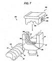
- FIG. 7 is a perspective view of an alternative of the head of the present dynamic vertebrae stabilization system.
- a rod assembly having protrusions is engaged with indentations in the U-slot and in the cap or vice versa (i.e., the indentions are in the flexible rod and the protrusions are in the anchor or U-shaped slot).
- a snap cap 90b including at least two cap projections couples the cap to the U-slot 40.
- the pedicle screw 20b includes a head 30 with a U-slot 40 connected to a bottom shank portion 28, which makes up part of the threaded shaft 74 (not shown).
- the interconnecting rod assembly 60 rather than being classically threaded, includes a pimpled surface 74b, including the individual pimples being disposed in a spiraling around the rod 74b in a threaded fastener-like pattern.
- the inner surface of the U-slot 40 likewise includes indentations, or receiving dimples 92b, inside which the protrusions 87 of the rod assembly 60' are fitted.
- the dimples being can be disposed in a spiraling around the rod 74b in a complementary threaded fastener-like pattern.
- the dimples 92b can be closely juxtaposed in the spiraling pattern to form a complementary threaded fastener-like pattern, or a thread groove allowing the rod to be threadably rotated in the U-slot 40 to enable the dimple spiral to act as a thread.
- the inner surface of the snap cap 90b also includes indentations, or receiving dimples 92b (not shown), for accepting the protrusions 87 on the top surface of the rod assembly 60, once the cap 90b is engaged with the head 30.
- the protrusions 87 and indentations are spherical in shape.
- the protrusions 87 of the pimpled surface 74b are arranged in latitudinal rows along the surface of the rod 60.
- the receiving dimples 92b inside the U-slot 40 are likewise arranged in latitudinal rows.
- the number of rows of receiving dimples 92b depends on the size of the head 30, with more rows providing a more stable engagement between pedicle screw 20b and rod assembly 60.
- the protrusions 87 are arranged in latitudinal rows
- the receiving dimples 92b are replaced with latitudinal grooves 97, as shown in FIG. 7 .
- the width of the latitudinal grooves is approximately the width of the rows of protrusions 87. This alternative has the characteristic of enabling rotational movement of the rod assembly 60 within the U-slot 40.
- the protrusions 87 are formed as square raised portions 87'. Inside the U-slot 40 and the cap 90b, corresponding square recesses 92b are formed to receive the raised portions 87'.
- the same head and cap arrangement described in FIG. 7 can be used with a rod 60', wherein the square raised portions 87' fit within the groove 92b.
- the surgeon can choose whether to restrain the rod 60' against relative rotation between the head 30 and cap 90b, at his discretion.
- the protrusions 87 are shaped like cubes, rods, or cylinders, with the U-slot 40 and cap 90b having cube-shaped, rod-shaped, or cylindrical receiving dimples for acceptance of the cubes, rods, or cylinders.
- the U-slot 40 and cap 90b having cube-shaped, rod-shaped, or cylindrical receiving dimples for acceptance of the cubes, rods, or cylinders.
- Designers of ordinary skill in the art recognize that there are a number of possibilities for mating the rod assembly 60 with the interior of the U-slot 40 and the cap 90b. Some of the embodiments may provide more stability and/or provide a better locking mechanism than others, while some alternatives may be easier and cheaper to manufacture.
- the pedicle screw 20b improves the locking of the rod assembly 60 into the head 30 of the pedicle screw.
- the pedicle screw 20b further protects against torsion or longitudinal sliding or slipping of the rod assembly 60 from the head 30.
- the pedicle screw 20b includes a cap 90b which includes at least two cap projections 93.
- the projections 93 are to be received in cap receivers 95 disposed in an inner wall of the U-slot 40.
- the cap 90b has a width equal to the width of the interior of the U-slot (shown as width w in FIGs. 7 and 8 ).
- the cap projections 93 and cap projection receivers 95 are designed such that the former fit snugly into the latter, but may be any of a variety of shapes known to those of ordinary skill in the art.
- the cap projections 93 are triangular prisms having a rectangular face 83 formed horizontally at the top, with a tapering of the prism at its bottom.
- the cap receivers 95 are triangular prism-shaped recesses, for receiving the cap projections upon insertion of the cap 90b.
- the cap projections 93 are preferably made using a material with some elasticity, such as an elastomeric material.
- the cap projections 93 may be squeezed against the inner wall of the U-slot until they are engaged with, and fill the space of, the cap receivers 95. Once engaged, the cap projections 93 preferably fill the entirety of the cap receivers 95 and are not removable therefrom.
- the rod assembly 60 In connecting the rod to the pedicle screw 20b, the rod assembly 60 is slid laterally through the opening of the U-slot 40, without the cap 90b. A preferred lateral position of the rod assembly is obtained, then the rod assembly 60 is rotated until the pimples 87 fit into the dimples 92b (or grooves, cubes). The cap 90b is then disposed atop the head 30 and fit into the U-slot 40.
- the first stage of the two stage anchor setting mechanism feature is accomplished by inserting the snap cap 90b into the screw head 30 so that only the first cap projection 93a is received into a first cap projection receiver 95b.
- the snap cap 90b engages the rod 74b sufficiently tightened sufficiently to just hold the rod 74b in place in the receiver U-slot 40.
- the protrusions 87 & 87' and the recesses 92b only relatively loosely engage the intervertebral rod 74b, and the intervertebral rod 74b is still rotatable/moveable within the screw head 30 and can be advanced or receded along its length l .
- the tension on the intervertebral rod 74b interconnecting two bone bridge points can be adjusted by rotating/moving the intervertebral rod 74b.
- the second stage of the anchor setting mechanism (74b, 90b, 92b, 95a, 95b, 93 a, 93b 87, 87', 97 & 97') is accomplished by further insertion of the snap cap 90b into the screw head 30 so that the second cap projection 93b is received into the cap projection receiver 95b.
- the first cap projection 93a can be received into another projection receiver 95a to give greater security to the insertion of the snap cap 90b.
Abstract
Description
- The present invention is in the field of surgical apparatus used in the treatment of diseases and other abnormal conditions of the spine. More specifically, the present invention relates to orthopedic instrumentation designed for attachment to a portion of the spine to correct a deformity, fracture, or unwanted diseased condition, wherein the means is particularly adapted for positioning vertebrae.
- The present invention relates to devices used in the surgical arts to fix the positional relationship of vertebrae of the spine, and more particularly to a pedicle screw and rod assembly for this purpose. There are various prior art devices available, which are intended for fixing the positional relationship of the vertebrae of the spine. For example, when attempting to achieve osteosynthesis, the specific fusion of different segments of the spine, one has to provide some type of immobilization. The current different systems typically involve placement of screws into the pedicle region of the vertebrae, which are then connected to each other by use of various sizes of rods, plates, or wires. However, these methods and devices for the fusion of vertebrae are not always appropriate when immobilization to promote fusion is not intended. Therefore, it would be beneficial to have a system with a somewhat flexible means of interconnecting the pedicle screws, and which would allow adjustment of the tension between at least two interconnected pedicle screws where the intent is to avoid fusion of the subject vertebrae.
- Spinal degeneration results in the loss of height between the vertebrae. This loss in height usually results in the pinching of a nerve which routes through the vertebrae, hence causing pain. In these cases it is often desirable to restore the spacing between the vertebrae rather than to fuse them. It would be additionally beneficial to have a device that would maintain the surgically restored resting height of the vertebrae, while allowing some flexion, extension and compression of those vertebrae relative to each other. Further, in view of the large number of pedicle screws available in the osteosynthesis field, it would be especially beneficial to have a device that accomplishes these objectives when combined or used with an existing type of osteosynthesis pedicle screw.
- In the published patent application
US 2003/0220642 , Freudinger disclosed an elastic stabilization system for vertebral columns having (a) an elastomeric, intervertebral rod having protrusions thereon and (b) a pedicle screw. Depending on the alternative embodiments, the system may also comprise a cap. The pedicle screw has a threaded shank and a head with a rod receiver. The rod receiver has formed therein corresponding structures adapted to engage the rod's protrusions. The cap is positioned in the rod receiver to firmly fix a non-threaded or non-grooved rod to the screw. The elastomeric intervertebral rod is prohibited from longitudinal sliding motions within the rod receiver because the threads/protrusions on the rod directly contact and engage the corresponding rod receiver's threads/grooves. - In
DE 196 46 534 A1 , Ahrens discloses a spinal column fixator having (a) an externally threaded intervertebral rod, (b) two spherical olives threaded on the intervertebral rod, (c) two screw-on caps having a pivotable disc, and (d) two pedicle screws. Each pedicle screw has a threaded shank and a head with a rod receiver. The rod receiver receives the olive that is threaded on the intervertebral rod on a first depression. Then, the pivotable disc, through a second depression, presses the olive. The preamble of claim 1 is based on this device. - From
DE 202 07 848 U1 , a spinal column fixator having an externally threaded or plane intervertebral rod is known. The plane rod is insertable into an admission slot of the pedicle screw head and fixed therein with a set screw. In another embodiment, the threaded rod is Fixed to the pedicle screw head with two locking screws that are screwed on the rod and against both sides of the pedicle screw head. - The present invention is a dynamic intervertebral stabilization system according to claim 1 for use in the surgical arts to fix the positional relationship of adjacent vertebrae of the spine. The present vertebral stabilization system is "dynamic" in that it allows some motion in the vertebrae while constraining it from over motion. Additionally, it is intended that the present system allow some compression and extension of the vertebrae relative to each other, while still maintaining the overall positional relationship within an appropriate range. The present vertebrae stabilization system comprises at least two pedicle screw assemblies used in combination. In use, two or more pedicle screw assemblies are interconnected in a series by a rod assembly, wherein the "dynamic" feature of the present invention resides, the dynamic feature being that the rod assembly preferably has some elasticity and can provide for some compression and extension over its length and distortion along its axis. The feature allows the vertebrae between which the present system is installed to move relative to each other, while still maintaining the normal overall positional relationship of the vertebrae within an appropriate range.
- A pedicle screw assembly of the present system has a threaded shaft and a screw head. The threaded shaft disposed to be screwed into a vertebra segment (typically into the pedicle bone), and the head disposed to connect to the dynamic rod assembly. The screw head has a bottom shank portion, a top surface and a head thickness portion therebetween. The bottom shank portion connects the screw head to the threaded shaft. A receiver portion for receiving and interfacing with a rod assembly is disposed in the top surface of the screw head. The receiver portion is where an anchor portion of the rod assembly is retained. The rod assembly can be of a polycarbonate urethane composition.
-
-
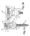
FIG. 1A is a front plan view of a pedicle screw and threaded rod of the present dynamic vertebrae stabilization system, showing front plan and side plan views of the screw head. -
FIG. 1B is a side view of the pedicle screw and threaded rod ofFIG. 1A . -
FIG. 2 is a partially disassembled side plan view of the head of a pedicle screw showing an alternative of the head for engaging a ball fastener and threaded rod combination. -
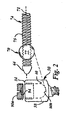
FIG. 3 is a partial cross-sectional side view of the head of a pedicle screw of the present invention showing an alternative embodiment wherein the anchor fastener is a hex nut engaging threaded rod. The hex fastener is fixed in place between the bottom of the U-slot and the set screw/cap. -
FIG. 4 is a partial cross-sectional side view of the head of a pedicle screw showing an alternative wherein a threaded wedge is used to fix the threaded cylinder in place in the screw head of the pedicle screw. -
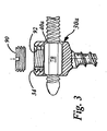
FIG. 5 is a side plan view of a threaded rod of the dynamic vertebral stabilization system illustrating different features for manually holding and rotating the rod. -
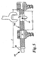
FIG. 6 is a partial cross-sectional view of the head and shank portions of a poly-axial pedicle screw of the present dynamic vertebrae stabilization system. -
FIG. 7 is a perspective view of the head of the present dynamic vertebrae stabilization system showing an alternative wherein a rod assembly having multiple spherical protrusions is engaged with corresponding indentations in the U-slot and in the cap. -
FIG. 8 is a perspective view of the head of the present dynamic vertebrae stabilization system showing a further alternative wherein a rod assembly having multiple square protrusions is engaged with corresponding indentations in the U-slot and in the cap. - The present invention is a dynamic vertebrae stabilization system for use in the surgical arts to fix the positional relationship of adjacent vertebrae of the spine. The present intervertebral stabilization system is "dynamic" in that it allows some motion in the vertebrae while constraining the vertebrae from over motion. Additionally, it is intended that the present system allow some compression and extension of the vertebrae relative to each other, while still maintaining the overall positional relationship within an appropriate range.
- As illustrated in
FIG. 1A and 1B , the present vertebral stabilization system comprises at least twopedicle screws 20, which are attachable to aninterconnecting rod assembly 60. Thepedicle screws 20 are intended typically to be anchored into the pedicle bone of adjacent vertebrae (not shown), with theinterconnecting rod assembly 60 disposed vertically between them. Also typically, at least two pedicle screw stabilization assemblies are used in a procedure, one stabilization system between the left pedicles of the adjacent vertebrae, and one stabilization system between the right pedicles of the same adjacent vertebrae. The component parts of the present vertebral stabilization system are constructed of materials that are bio-compatible and preferably are additionally MRI-compatible. In fact, the embodiment ofFIGs. 1A and 1B is intended to be practiced with an existing pedicle screw, while still accomplishing the benefits of the present dynamic stabilization system. - The pedicle screws 20 have a threaded shaft 24 and a
head 30. The threaded shaft 24 is formed to be screwed into a vertebra segment proximate to pedicle bone. Methods and means for inserting thepedicle screw 20 into vertebrae are known in the art. Thepedicle screw head 30 has abottom shank portion 28 by which it is attached to the threaded shaft 24. Thescrew head 30 also has atop surface 34 at a height h above thebottom shank portion 28 and a head thickness t across thetop surface 34 and between the slot faces 38 of thescrew head 30. Thescrew head 30 is adapted to engage a threadedanchor 70 typically proximate therod end 64 of the interconnectingrod assembly 60. - In a preferred embodiment exemplified in
FIG. 1 , thescrew head 30 is adapted to engage therod assembly 60 via arod receiver 40 disposed in thetop surface 34 of thescrew head 30. In the embodiment illustrated, therod receiver 40 is a U-slot 40 adapted to receive and retain theanchor 70 of therod assembly 60. The U-slot 40 is an opening between the slot faces 38 and communicates with thetop surface 34 of thescrew head 30. Typically, arod end 64 projects through the U-slot 40. The U-slot 40 has a width w, a depth d and a slot thickness t. The slot thickness t corresponds to the head thickness t of thetop surface 34. The depth d is the distance the U-slot 40 extends from thetop surface 34 toward thebottom shank portion 28 of thescrew head 30. - The interconnecting
rod assembly 60 has a connectingrod 74 with multifaceted surface portions which are threadedportions 75 and first and second rod ends 64, a rod diameter rd and a rod length l. The threadedrod 74 has the feature of being somewhat elastic, in that it is capable of being stretched, compressed and flexed over its length l along itsaxis 71. In a preferred embodiment, a threadedrod 74 having the intended features is made of a polycarbonate urethane composition, and has a rod diameter rd of about 4.0mm. An advantage of the polycarbonate urethane threadedrod 74 is that this material acts as a good dampener to the motion along its length, but can be rigidly attached to the pedicle screws 20. In the preferred embodiment illustrated, therod assembly 60 has arigid anchor 70 that is a threadedcylinder 76 screwed onto the threadedrod 74 from arod end 64. Theanchor 70, regardless of its configuration, which may be of just about any polygonal or cylindrical form, has a cross-sectional dimension fd that allows theanchor 70 to be received into the width w of the U-slot 40. The width w of theslot 40 of a typical existing pedicle screw is about 5.5mm to 6.0mm. Therefore, the cross-sectional dimension fd of theanchor 70 is selected to closely approach the width w of theslot 40 of thepedicle screw 20 being used with the present system. - Interconnection between the
screw head 30 and therod assembly 60 is accomplished by the threadedrod 74 being receivable along a portion of its length l into the width w of the U-slot 40 to a depth exceeding the rod diameter rd . With the threadedrod 74 received in the U-slot 40, theanchor 70 is fixable along the length of the threadedrod 74 by screwing aset screw 90 into aset screw receiver 92 of thepedicle screw 20, and tightening theset screw 90 against theanchor 70. In the preferred embodiment shown, tightening theset screw 90 against theanchor 70 is provided with a two stage anchor setting mechanism. In the first stage, theset screw 90 is tightened sufficiently to only fix theanchor 70 in thereceiver U-slot 40. At this stage theintervertebral rod 74 is still rotatable within theanchor 70, but theanchor 70 cannot move relatively to thescrew head 38. The tension on theintervertebral rod 74 interconnecting two similarly captured/fixed pedicle screw anchors 70 can be adjusted by rotating the threadedrod 74. Subsequent further tightening of theset screw 92 compresses theanchor 70 against the threadedrod 74 like a swage fitting to additionally fix the positional relationship of the anchor and the threadedrod 74. Optionally, theanchor 70 can have a through-slot 69 going from its outside surface to its inside surface, the through-slot 69 providing compression or crush space to facilitate compression of theanchor 70. - The threaded
set screw 90 is screwed into the complementary-threadedreceiver 92 in thetop surface 34 of thescrew head 30. The threaded set/cap screw 90 can function to hold theanchor 70 fixed in place in thepedicle screw 20 while the length of therod assembly 60 is being adjusted to obtain the desired distance between the twopedicle screws 20 of the system. Once the distance relationship is appropriately set, theset screws 90 can be further tightened to fully set theanchor 70 to the threadedrod 74 and prevent its inadvertent rotation and to prevent any slippage or loosening of therod 74 that might otherwise occur. Theset screw cap 90 illustrated is configured as a slotted set screw, but other configurations of theretainer cap 90 suitable for practice in the present invention are known to and selectable by one of ordinary skill in the art. - Other configurations of the
screw head 30 andanchor 70 combination are , for example, shown inFIG. 2 . Theanchor 70 comprises a spherical/ball threaded fastener 77, which is received in acomplementary detent recess 80b integral with the U-slot 40 of thescrew head 30, i.e., thedetent recess 80b is completely within thescrew head 30. In this embodiment the set screw cap 90a has a concavelower face 94 that is complementary to the ball fastener 77, to closely receive the ball fastener 77 when the set screw 90a is screwed into place. -
FIG. 3 illustrates an example of a further alternative embodiment of thescrew head 30a, and how it can interconnect with therod assembly 60. In the embodiment exemplified inFIG. 3 , thescrew head 30a has arod receiver passage 40a such as a hexagonally shaped passage rather than a U-slot rod receiver. Pedicle screws with rod receiver passages are known in the art. Therod receiver passage 40a communicates with theset screw receiver 92, which allows theset screw 90 to encroach into therod receiver passage 40a. Theanchor 70 is a threaded hex-fastener 78 that is set against the bottom of therod receiver passage 40a proximate to thebottom shank 28 of thepedicle screw 20. Setting the threaded hex-fastener 78 against the bottom of therod receiver passage 40a is accomplished as disclosed above via the action of tightening theset screw 90. -
FIG. 4 illustrates an example of a further alternative of thepedicle screw 20 having ascrew head 30b for receiving the threaded connectingrod 74. Thescrew head 30b includes threads 86 disposed at a base portion of the U-slotted receiver 40b and a matching threadedwedge 88, to be inserted into the top of the U-slot. When the threaded connectingrod 74 is positioned inside the receiver 40b against the threads 86, the threadedwedge 88 is inserted on top of therod 74 through the top of theset screw hole 89 of theset screw receiver 92 to mate with the threads of the threaded rod. 74. Then theset screw 90 is screwed into theset screw receiver 92 of the U-slot 40b against the threadedwedge 88. In this manner, the threadedwedge 88 is forced against and applies pressure to the threaded connectingrod 74, affixing it into thepedicle screw 20, but not preventing therod 74 from being rotatable. The connectingrod 74 is then rotated to obtain the desired distance between the twopedicle screws 20 making up the pedicle screw stabilization system. -
FIG. 5 illustrates a portion of the length l of a threaded rod 74a, of the dynamic vertebrae stabilization system. The combination of this configuration of dynamic rod 74a with the present pedicle screws 20 forms a "turnbuckle" type mechanism which allows adjustment of the tension between at least two interconnected pedicle screws, which is a benefit, for example, where the intent is to avoid fusion of the subject vertebrae. The unshown portion of a threaded rod 74a is substantially similar to the portions shown in the figures. In the embodiment of the threaded rod 74a illustrated, the opposite ends 64 of the rod 74a are threaded in opposite directions. The threaded rod 74a ofFIG. 5 illustrates different features of a threaded rod that can be used to provide alternative means for manually holding and/or rotating the threaded rod 74a to achieve the desired positional relationship between the at least twopedicle screws 20 of the system. Therein, the threaded rod 74a is engageable at arod end 64, which is has a hex-head 66 configuration, or at some position along its length l where it has a hex-nut 68 configuration in which the nut moves with the rod. It can be seen that in this configuration, turning of the hex-nut 68 causes the distance between two adjacent pedicle screws to vary, thus permitting the distance between adjacent vertebrae to be adjusted. Other configurations of the threadedrod 74 with means for manually holding and/or rotating therod 74, which are suitable for practice in the present invention are known to and selectable by one of ordinary skill in the art. -
FIG. 6 illustrates the head and shank portions of a poly-axial type pedicle screw practicable in the present dynamic stabilization system. Such poly-axial pedicle screws are known in the field. For example, seeUS Patent No. 6,869433 to Glascott . In the example illustrated, theshank portion 28a of the pedicle screw 20 a comprises a ball and socket swivel joint, with the screw shaft 24a terminating in theball 50 of the joint, and the bottom of the U-slot 40a being thesocket 54 of the joint. The bottom of the U-slot 40a has a shaft port 98 formed therein to allow the screw shaft 24a to pass through and extend from theshank portion 28a. - A swage-
like fitting 96 is formed between theball 50 and the threadedfitting 70. The swage fitting 96 is contoured where its surfaces contact theball 50 and the threadedfitting 70. Driving theset screw 90 against the threaded fitting 70 causes a compressive force to be exerted on the components between theset screw 90 and thesocket 54. In this manner, the threadedfitting 70 is compressed against both the threadedrod 74 and the swage-like fitting 96. In turn, theball 50 is compressed between the swage fitting 96 and thesocket 54. Compression of the noted components in this manner sets and secures their positional relationship to each other, and locks the angular position of thescrew head 30a with respect to the shaft 24a. Other poly-axial pedicle screws are known to and selectable by the ordinary skilled artisan for practice in the present pedicle screw dynamic stabilization system. - In a preferred embodiment, the vertebral stabilization system utilizes a threaded
polycarbonate urethane rod 74 with an outside diameter (o.d.) rd of about 4.0mm. Ananchor 70, in the form of a threadedtitanium cylinder 76, is screwed onto eachend 64 of therod 74 as inFIG. 1 . In this example, thecylinders 76 have an o.d. fd of about 5.5mm to 6.0mm. The distance between twoanchors 70 or between ananchor 70 and the correspondingrod end 64 is adjustable by threading one or bothanchor 70 along the length of therod 74. -
FIG. 7 is a perspective view of an alternative of the head of the present dynamic vertebrae stabilization system. In contrast to the threaded assemblies previously depicted, a rod assembly having protrusions is engaged with indentations in the U-slot and in the cap or vice versa (i.e., the indentions are in the flexible rod and the protrusions are in the anchor or U-shaped slot). Instead of a set/cap screw (FIG. 1 ), asnap cap 90b including at least two cap projections couples the cap to the U-slot 40. - As in the
pedicle screw 20 of the previous embodiments, thepedicle screw 20b includes ahead 30 with a U-slot 40 connected to abottom shank portion 28, which makes up part of the threaded shaft 74 (not shown). The interconnectingrod assembly 60, rather than being classically threaded, includes apimpled surface 74b, including the individual pimples being disposed in a spiraling around therod 74b in a threaded fastener-like pattern. The inner surface of the U-slot 40 likewise includes indentations, or receivingdimples 92b, inside which theprotrusions 87 of the rod assembly 60' are fitted. The dimples being can be disposed in a spiraling around therod 74b in a complementary threaded fastener-like pattern. Also, thedimples 92b can be closely juxtaposed in the spiraling pattern to form a complementary threaded fastener-like pattern, or a thread groove allowing the rod to be threadably rotated in the U-slot 40 to enable the dimple spiral to act as a thread. The inner surface of thesnap cap 90b also includes indentations, or receivingdimples 92b (not shown), for accepting theprotrusions 87 on the top surface of therod assembly 60, once thecap 90b is engaged with thehead 30. InFIG. 7 , theprotrusions 87 and indentations are spherical in shape. - In one alternative, the
protrusions 87 of thepimpled surface 74b are arranged in latitudinal rows along the surface of therod 60. The receivingdimples 92b inside the U-slot 40 are likewise arranged in latitudinal rows. The number of rows of receivingdimples 92b depends on the size of thehead 30, with more rows providing a more stable engagement betweenpedicle screw 20b androd assembly 60. In another alternative, where theprotrusions 87 are arranged in latitudinal rows, the receivingdimples 92b are replaced withlatitudinal grooves 97, as shown inFIG. 7 . The width of the latitudinal grooves is approximately the width of the rows ofprotrusions 87. This alternative has the characteristic of enabling rotational movement of therod assembly 60 within theU-slot 40. - Referring now to
FIG. 8 , in another alternative, theprotrusions 87 are formed as square raised portions 87'. Inside the U-slot 40 and thecap 90b, correspondingsquare recesses 92b are formed to receive the raised portions 87'. Alternatively, the same head and cap arrangement described inFIG. 7 can be used with a rod 60', wherein the square raised portions 87' fit within thegroove 92b. Thus, the surgeon can choose whether to restrain the rod 60' against relative rotation between thehead 30 andcap 90b, at his discretion. - In another alternative, the
protrusions 87, rather than being spherical in shape, are shaped like cubes, rods, or cylinders, with the U-slot 40 andcap 90b having cube-shaped, rod-shaped, or cylindrical receiving dimples for acceptance of the cubes, rods, or cylinders. Designers of ordinary skill in the art recognize that there are a number of possibilities for mating therod assembly 60 with the interior of the U-slot 40 and thecap 90b. Some of the embodiments may provide more stability and/or provide a better locking mechanism than others, while some alternatives may be easier and cheaper to manufacture. - The
pedicle screw 20b improves the locking of therod assembly 60 into thehead 30 of the pedicle screw. Thepedicle screw 20b further protects against torsion or longitudinal sliding or slipping of therod assembly 60 from thehead 30. Instead of a set/cap screw 90 (FIG. 1 ), thepedicle screw 20b includes acap 90b which includes at least two cap projections 93. The projections 93 are to be received in cap receivers 95 disposed in an inner wall of the U-slot 40. Thecap 90b has a width equal to the width of the interior of the U-slot (shown as width w inFIGs. 7 and8 ). - The cap projections 93 and cap projection receivers 95 are designed such that the former fit snugly into the latter, but may be any of a variety of shapes known to those of ordinary skill in the art. In the alternative of
FIGs. 7 and8 , the cap projections 93 are triangular prisms having arectangular face 83 formed horizontally at the top, with a tapering of the prism at its bottom. Likewise, the cap receivers 95 are triangular prism-shaped recesses, for receiving the cap projections upon insertion of thecap 90b. The cap projections 93 are preferably made using a material with some elasticity, such as an elastomeric material. This ensures that, when thecap 90b is inserted into the U-slot 40, the cap projections 93 may be squeezed against the inner wall of the U-slot until they are engaged with, and fill the space of, the cap receivers 95. Once engaged, the cap projections 93 preferably fill the entirety of the cap receivers 95 and are not removable therefrom. - In connecting the rod to the
pedicle screw 20b, therod assembly 60 is slid laterally through the opening of the U-slot 40, without thecap 90b. A preferred lateral position of the rod assembly is obtained, then therod assembly 60 is rotated until thepimples 87 fit into thedimples 92b (or grooves, cubes). Thecap 90b is then disposed atop thehead 30 and fit into the U-slot 40. - In the preferred alternatives shown, the first stage of the two stage anchor setting mechanism feature is accomplished by inserting the
snap cap 90b into thescrew head 30 so that only thefirst cap projection 93a is received into a firstcap projection receiver 95b. In the first stage, thesnap cap 90b engages therod 74b sufficiently tightened sufficiently to just hold therod 74b in place in thereceiver U-slot 40. At this stage, theprotrusions 87 & 87' and therecesses 92b only relatively loosely engage theintervertebral rod 74b, and theintervertebral rod 74b is still rotatable/moveable within thescrew head 30 and can be advanced or receded along its length l . In this configuration, the tension on theintervertebral rod 74b interconnecting two bone bridge points can be adjusted by rotating/moving theintervertebral rod 74b. The second stage of the anchor setting mechanism (74b, 90b, 92b, 95a, 95b, 93 a,93b snap cap 90b into thescrew head 30 so that thesecond cap projection 93b is received into thecap projection receiver 95b. Thefirst cap projection 93a can be received into anotherprojection receiver 95a to give greater security to the insertion of thesnap cap 90b. This deeper insertion of thesnap cap 90b bears on the compressesintervertebral rod 74b sufficiently to fully engage theprotrusions 87 & 87' and therecesses 92b fix the position of theintervertebral rod 74b to thepedicle screw 30.
Claims (10)
- A dynamic vertebral stabilization system for correcting a spinal deformity, fracture, or unwanted diseased condition, comprising:(a) at least a first and a second pedicle screw (20) installable at an initial distance ΔD in adjacent vertebrae of a subject, each pedicle screw (20) having a threaded shaft (24) formed to be screwed into a vertebra segment and a head (30) which is attached to the shaft (24), each pedicle screw head (30) having an anchor receiver slot (40) or an anchor receiving passage (40a) and a set screw receiver (92) formed at the top of the anchor receiver slot (40) or the anchor receiving passage (40a);(b) at least a first and a second set screw (90), for being screwed into the set screw receivers (92) of said two pedicle screws (20);(c) an externally threaded connecting rod (74) with a longitudinal axis (71);(d) at least a first and a second anchor (70), each having a cross-sectional dimension to be received in one of the anchor receiver slots (40) or anchor receiving passages (40a) of said two pedicle screws (20), and each anchor (70) having internal threads disposed therein, the threads of the anchors (70) being complementary to the threads of the connecting rod (74);wherein the externally threaded connecting rod (74) at least comprises the first and the second anchor (70) screwed thereon and positioned relative to each other in substantially the initial distance ΔD,
characterized in that the externally threaded connecting rod (74) is elastomeric, wherein said rod is compressible and extendable over part of its length and distortable along said axis,
and in that the first and second anchors (70) - when they are received in the anchor receiver slots (40) or in the anchor receiving passages (40a) of the respective pedicle screw heads (30) - are slidingly movable in direction of the connecting rod axis (71) with the first and second set screws (90) screwed into the set screw receivers (92) of the pedicle screw heads (30) without tightening and without compressing the first and second anchor, thus enabling adjustment of the initial distance ΔD to an appropriately set distance prior to further tightening the first and second set screws (90). - The dynamic vertebral stabilization system of claim 1, characterized in that adjustment of the initial distance ΔD to an appropriately set distance is achievable without changing the distance between the first and second anchors (70) by slipping the first or second anchor (70) within the respective anchor receiver slot (40) or receiving passage (40a) in direction of the axis (71) of the connecting rod (74) until the spinal deformity, fracture, or unwanted diseased condition is corrected.
- The dynamic vertebral stabilization system of claim 2, characterized in that fine adjustment of the initial distance ΔD to an appropriately set distance is achievable through additional changing the distance between the first and second anchors (70) by tightening the first and second set screws (90) sufficiently to fix the anchors (70) in the respective anchor receiver slots (40) or receiving passages (40a) in the pedicle screw heads (30), and by rotating the threaded rod (74) that has two threads in opposite directions until the spinal deformity, fracture, or unwanted diseased condition is corrected.
- The dynamic vertebral stabilization system of one of the preceding claims, characterized in that the anchor receiver slot (40) is a U-slot opening between slot faces (38) of the screw head (30) and communicating with a top surface (34) of the screw head (30) through the set screw receiver (92).
- The dynamic vertebral stabilization system of one of the claims 1 to 3, characterized in that the anchor receiving passage (40a) is a hexagonally shaped cross-sectional passage communicating with a top surface (34) of the screw head (30) through the set screw receiver (92) allowing the set screw (90) to encroach into the anchor receiving passage (40a).
- The dynamic vertebral stabilization system of one of the preceding claims, characterized in that the anchors (70) are selected from a group of anchors having cylindrical, polygonal, or hexagonal cross-sectional shape.
- The dynamic vertebral stabilization system of claim 6, characterized in that the anchors (70) further comprise a through slot (69) going from the anchor's outside surface to the anchor's inside surface and providing compression or crush space to facilitate compression of the anchors.
- The dynamic vertebral stabilization system of one of the preceding claims, characterized in that the first set screw (90) is adapted to tighten the first anchor (70) in its anchor receiver slot (40) or anchor receiving passage (40a) after the first anchor (70) is longitudinally slid.
- The dynamic vertebral stabilization system of one of the preceding claims, characterized in that the connecting rod (74) comprises a polycarbonate urethane composition.
- The dynamic vertebral stabilization system of one of the preceding claims, characterized in that the connecting rod (74) has an outside diameter of at least 3.5 mm.
Applications Claiming Priority (3)
| Application Number | Priority Date | Filing Date | Title |
|---|---|---|---|
| US74528206P | 2006-04-21 | 2006-04-21 | |
| US87189406P | 2006-12-26 | 2006-12-26 | |
| PCT/IB2007/001050 WO2007122494A2 (en) | 2006-04-21 | 2007-04-21 | Dynamic intervertebral stabilization system |
Publications (2)
| Publication Number | Publication Date |
|---|---|
| EP2015692A2 EP2015692A2 (en) | 2009-01-21 |
| EP2015692B1 true EP2015692B1 (en) | 2010-10-27 |
Family
ID=38625373
Family Applications (1)
| Application Number | Title | Priority Date | Filing Date |
|---|---|---|---|
| EP07734369A Active EP2015692B1 (en) | 2006-04-21 | 2007-04-21 | Dynamic intervertebral stabilization system |
Country Status (5)
| Country | Link |
|---|---|
| US (1) | US8088149B2 (en) |
| EP (1) | EP2015692B1 (en) |
| AT (1) | ATE485779T1 (en) |
| DE (1) | DE602007010120D1 (en) |
| WO (1) | WO2007122494A2 (en) |
Families Citing this family (73)
| Publication number | Priority date | Publication date | Assignee | Title |
|---|---|---|---|---|
| US7833250B2 (en) | 2004-11-10 | 2010-11-16 | Jackson Roger P | Polyaxial bone screw with helically wound capture connection |
| US8292926B2 (en) | 2005-09-30 | 2012-10-23 | Jackson Roger P | Dynamic stabilization connecting member with elastic core and outer sleeve |
| US10258382B2 (en) | 2007-01-18 | 2019-04-16 | Roger P. Jackson | Rod-cord dynamic connection assemblies with slidable bone anchor attachment members along the cord |
| US8353932B2 (en) | 2005-09-30 | 2013-01-15 | Jackson Roger P | Polyaxial bone anchor assembly with one-piece closure, pressure insert and plastic elongate member |
| US7862587B2 (en) | 2004-02-27 | 2011-01-04 | Jackson Roger P | Dynamic stabilization assemblies, tool set and method |
| US10729469B2 (en) | 2006-01-09 | 2020-08-04 | Roger P. Jackson | Flexible spinal stabilization assembly with spacer having off-axis core member |
| US8876868B2 (en) | 2002-09-06 | 2014-11-04 | Roger P. Jackson | Helical guide and advancement flange with radially loaded lip |
| US7621918B2 (en) | 2004-11-23 | 2009-11-24 | Jackson Roger P | Spinal fixation tool set and method |
| US7377923B2 (en) | 2003-05-22 | 2008-05-27 | Alphatec Spine, Inc. | Variable angle spinal screw assembly |
| US7766915B2 (en) | 2004-02-27 | 2010-08-03 | Jackson Roger P | Dynamic fixation assemblies with inner core and outer coil-like member |
| US8398682B2 (en) | 2003-06-18 | 2013-03-19 | Roger P. Jackson | Polyaxial bone screw assembly |
| US8926670B2 (en) | 2003-06-18 | 2015-01-06 | Roger P. Jackson | Polyaxial bone screw assembly |
| US8814911B2 (en) | 2003-06-18 | 2014-08-26 | Roger P. Jackson | Polyaxial bone screw with cam connection and lock and release insert |
| US7776067B2 (en) | 2005-05-27 | 2010-08-17 | Jackson Roger P | Polyaxial bone screw with shank articulation pressure insert and method |
| US8137386B2 (en) | 2003-08-28 | 2012-03-20 | Jackson Roger P | Polyaxial bone screw apparatus |
| US8377102B2 (en) | 2003-06-18 | 2013-02-19 | Roger P. Jackson | Polyaxial bone anchor with spline capture connection and lower pressure insert |
| US7527638B2 (en) | 2003-12-16 | 2009-05-05 | Depuy Spine, Inc. | Methods and devices for minimally invasive spinal fixation element placement |
| US11419642B2 (en) | 2003-12-16 | 2022-08-23 | Medos International Sarl | Percutaneous access devices and bone anchor assemblies |
| US7179261B2 (en) | 2003-12-16 | 2007-02-20 | Depuy Spine, Inc. | Percutaneous access devices and bone anchor assemblies |
| US11241261B2 (en) | 2005-09-30 | 2022-02-08 | Roger P Jackson | Apparatus and method for soft spinal stabilization using a tensionable cord and releasable end structure |
| US7160300B2 (en) | 2004-02-27 | 2007-01-09 | Jackson Roger P | Orthopedic implant rod reduction tool set and method |
| US8152810B2 (en) | 2004-11-23 | 2012-04-10 | Jackson Roger P | Spinal fixation tool set and method |
| EP1720468A4 (en) | 2004-02-27 | 2010-01-27 | Roger P Jackson | Orthopedic implant rod reduction tool set and method |
| US7651502B2 (en) | 2004-09-24 | 2010-01-26 | Jackson Roger P | Spinal fixation tool set and method for rod reduction and fastener insertion |
| JP2008519656A (en) | 2004-11-10 | 2008-06-12 | ロジャー・ピー・ジャクソン | Helical guide and forward flange with break extension |
| US8926672B2 (en) | 2004-11-10 | 2015-01-06 | Roger P. Jackson | Splay control closure for open bone anchor |
| US9216041B2 (en) | 2009-06-15 | 2015-12-22 | Roger P. Jackson | Spinal connecting members with tensioned cords and rigid sleeves for engaging compression inserts |
| WO2006057837A1 (en) | 2004-11-23 | 2006-06-01 | Jackson Roger P | Spinal fixation tool attachment structure |
| US9980753B2 (en) | 2009-06-15 | 2018-05-29 | Roger P Jackson | pivotal anchor with snap-in-place insert having rotation blocking extensions |
| US8444681B2 (en) | 2009-06-15 | 2013-05-21 | Roger P. Jackson | Polyaxial bone anchor with pop-on shank, friction fit retainer and winged insert |
| US9918745B2 (en) | 2009-06-15 | 2018-03-20 | Roger P. Jackson | Polyaxial bone anchor with pop-on shank and winged insert with friction fit compressive collet |
| US9168069B2 (en) | 2009-06-15 | 2015-10-27 | Roger P. Jackson | Polyaxial bone anchor with pop-on shank and winged insert with lower skirt for engaging a friction fit retainer |
| US8308782B2 (en) | 2004-11-23 | 2012-11-13 | Jackson Roger P | Bone anchors with longitudinal connecting member engaging inserts and closures for fixation and optional angulation |
| US10076361B2 (en) | 2005-02-22 | 2018-09-18 | Roger P. Jackson | Polyaxial bone screw with spherical capture, compression and alignment and retention structures |
| US7901437B2 (en) | 2007-01-26 | 2011-03-08 | Jackson Roger P | Dynamic stabilization member with molded connection |
| US8105368B2 (en) | 2005-09-30 | 2012-01-31 | Jackson Roger P | Dynamic stabilization connecting member with slitted core and outer sleeve |
| CA2670988C (en) | 2006-12-08 | 2014-03-25 | Roger P. Jackson | Tool system for dynamic spinal implants |
| US8475498B2 (en) | 2007-01-18 | 2013-07-02 | Roger P. Jackson | Dynamic stabilization connecting member with cord connection |
| US8366745B2 (en) | 2007-05-01 | 2013-02-05 | Jackson Roger P | Dynamic stabilization assembly having pre-compressed spacers with differential displacements |
| US8979904B2 (en) | 2007-05-01 | 2015-03-17 | Roger P Jackson | Connecting member with tensioned cord, low profile rigid sleeve and spacer with torsion control |
| US10383660B2 (en) | 2007-05-01 | 2019-08-20 | Roger P. Jackson | Soft stabilization assemblies with pretensioned cords |
| US8221471B2 (en) | 2007-05-24 | 2012-07-17 | Aesculap Implant Systems, Llc | Pedicle screw fixation system |
| US20090093820A1 (en) * | 2007-10-09 | 2009-04-09 | Warsaw Orthopedic, Inc. | Adjustable spinal stabilization systems |
| ES2353033T5 (en) * | 2008-03-28 | 2014-01-20 | Biedermann Technologies Gmbh & Co. Kg | Bone anchoring device |
| ES2378171T3 (en) * | 2008-05-13 | 2012-04-09 | Spinelab Ag | Pedicle screw with a locking mechanism |
| EP2442739A1 (en) | 2008-08-01 | 2012-04-25 | Jackson, Roger P. | Longitudinal connecting member with sleeved tensioned cords |
| EP2198792A1 (en) * | 2008-12-19 | 2010-06-23 | Sepitec Foundation | Implant system for stabilising bones |
| US9668771B2 (en) | 2009-06-15 | 2017-06-06 | Roger P Jackson | Soft stabilization assemblies with off-set connector |
| US11229457B2 (en) | 2009-06-15 | 2022-01-25 | Roger P. Jackson | Pivotal bone anchor assembly with insert tool deployment |
| US8998959B2 (en) | 2009-06-15 | 2015-04-07 | Roger P Jackson | Polyaxial bone anchors with pop-on shank, fully constrained friction fit retainer and lock and release insert |
| AU2010303934B2 (en) | 2009-10-05 | 2014-03-27 | Roger P. Jackson | Polyaxial bone anchor with non-pivotable retainer and pop-on shank, some with friction fit |
| US9017387B2 (en) * | 2009-12-19 | 2015-04-28 | James H. Aldridge | Apparatus and system for vertebrae stabilization and curvature correction, and methods of making and using same |
| US8968367B2 (en) | 2010-01-05 | 2015-03-03 | The Johns Hopkins University | Compression-distraction spinal fixation system and kit |
| US8864800B2 (en) * | 2010-01-05 | 2014-10-21 | The Johns Hopkins University | Compression-distraction spinal fixation system |
| US20120046698A1 (en) * | 2010-08-18 | 2012-02-23 | Doctors Research Group, Inc. | Methods and devices for spinal fusion |
| EP2613719A1 (en) | 2010-09-08 | 2013-07-17 | Roger P. Jackson | Dynamic stabilization members with elastic and inelastic sections |
| JP2013545527A (en) | 2010-11-02 | 2013-12-26 | ロジャー・ピー・ジャクソン | Multi-axis bone anchor with pop-on shank and pivotable retainer |
| WO2012128825A1 (en) | 2011-03-24 | 2012-09-27 | Jackson Roger P | Polyaxial bone anchor with compound articulation and pop-on shank |
| US8523922B2 (en) | 2011-10-24 | 2013-09-03 | Warsaw Orthopedic | Dynamic multi-axial fastener |
| US8911479B2 (en) | 2012-01-10 | 2014-12-16 | Roger P. Jackson | Multi-start closures for open implants |
| EP2877109A4 (en) * | 2012-07-24 | 2016-03-23 | Carbofix In Orthopedics Llc | Spine system and kit |
| US8911478B2 (en) | 2012-11-21 | 2014-12-16 | Roger P. Jackson | Splay control closure for open bone anchor |
| US10058354B2 (en) | 2013-01-28 | 2018-08-28 | Roger P. Jackson | Pivotal bone anchor assembly with frictional shank head seating surfaces |
| US8852239B2 (en) | 2013-02-15 | 2014-10-07 | Roger P Jackson | Sagittal angle screw with integral shank and receiver |
| US9064307B2 (en) | 2013-06-28 | 2015-06-23 | General Electric Company | Methods and apparatus to generate three-dimensional spinal renderings |
| US9566092B2 (en) | 2013-10-29 | 2017-02-14 | Roger P. Jackson | Cervical bone anchor with collet retainer and outer locking sleeve |
| US9717533B2 (en) | 2013-12-12 | 2017-08-01 | Roger P. Jackson | Bone anchor closure pivot-splay control flange form guide and advancement structure |
| US9451993B2 (en) | 2014-01-09 | 2016-09-27 | Roger P. Jackson | Bi-radial pop-on cervical bone anchor |
| US10064658B2 (en) | 2014-06-04 | 2018-09-04 | Roger P. Jackson | Polyaxial bone anchor with insert guides |
| US9597119B2 (en) | 2014-06-04 | 2017-03-21 | Roger P. Jackson | Polyaxial bone anchor with polymer sleeve |
| US9649132B1 (en) * | 2015-04-20 | 2017-05-16 | Donald W. Linck | Bone distractor |
| US10543022B2 (en) * | 2016-10-11 | 2020-01-28 | Warsaw Orthopedic, Inc. | Spinal implant system and method |
| CN108186093B (en) * | 2018-01-25 | 2024-03-08 | 何伟义 | Cushion block capable of generating switching function |
Family Cites Families (23)
| Publication number | Priority date | Publication date | Assignee | Title |
|---|---|---|---|---|
| US4274401A (en) * | 1978-12-08 | 1981-06-23 | Miskew Don B W | Apparatus for correcting spinal deformities and method for using |
| FR2545350B1 (en) * | 1983-05-04 | 1985-08-23 | Cotrel Yves | DEVICE FOR SHRINKAGE OF THE RACHIS |
| US4743260A (en) * | 1985-06-10 | 1988-05-10 | Burton Charles V | Method for a flexible stabilization system for a vertebral column |
| DE3614101C1 (en) * | 1986-04-25 | 1987-10-22 | Juergen Prof Dr Med Harms | Pedicle screw |
| CH681853A5 (en) * | 1990-08-21 | 1993-06-15 | Synthes Ag | |
| US5257994A (en) * | 1991-09-23 | 1993-11-02 | Lin Chih I | Vertebral locking and retrieving system |
| US5281222A (en) * | 1992-06-30 | 1994-01-25 | Zimmer, Inc. | Spinal implant system |
| US5382248A (en) * | 1992-09-10 | 1995-01-17 | H. D. Medical, Inc. | System and method for stabilizing bone segments |
| US5352226A (en) * | 1993-02-08 | 1994-10-04 | Lin Chih I | Side locking system rotatable in all directions for use in spinal surgery |
| FR2702362B3 (en) * | 1993-02-24 | 1995-04-14 | Soprane Sa | Fixator for osteosynthesis of the lumbosacral spine. |
| DE4316542C1 (en) * | 1993-05-18 | 1994-07-21 | Schaefer Micomed Gmbh | Osteosynthesis device |
| US5961517A (en) * | 1994-07-18 | 1999-10-05 | Biedermann; Lutz | Anchoring member and adjustment tool therefor |
| FR2731344B1 (en) * | 1995-03-06 | 1997-08-22 | Dimso Sa | SPINAL INSTRUMENTATION ESPECIALLY FOR A ROD |
| DE19646534B4 (en) | 1996-10-30 | 2005-03-10 | Aap Implantate Ag | spine fixator |
| DE19818765A1 (en) * | 1998-04-07 | 1999-10-14 | Schaefer Micomed Gmbh | Synthetic bone device for fixing bone fractures |
| US6302410B1 (en) * | 1999-10-22 | 2001-10-16 | Earth Tool Company, L.L.C. | Rod gripping jaw |
| DE20207848U1 (en) | 2002-05-21 | 2002-10-10 | Metz Stavenhagen Peter | Anchoring element, in particular pedicle screw, for fastening a rod of a device for setting up a human or animal spine to a vertebral bone |
| EP1364622B1 (en) * | 2002-05-21 | 2005-07-20 | Spinelab GmbH | Elastical system for stabilising the spine |
| US7473267B2 (en) * | 2003-04-25 | 2009-01-06 | Warsaw Orthopedic, Inc. | System and method for minimally invasive posterior fixation |
| US7766915B2 (en) * | 2004-02-27 | 2010-08-03 | Jackson Roger P | Dynamic fixation assemblies with inner core and outer coil-like member |
| WO2005102195A1 (en) * | 2004-04-20 | 2005-11-03 | Allez Spine, Llc | Pedicle screw assembly |
| US7763049B2 (en) * | 2004-06-09 | 2010-07-27 | Zimmer Spine, Inc. | Orthopedic fixation connector |
| JP2008534080A (en) | 2005-03-23 | 2008-08-28 | アルファスパイン インコーポレイテッド | Percutaneous pedicle screw assembly |
-
2007
- 2007-04-21 EP EP07734369A patent/EP2015692B1/en active Active
- 2007-04-21 AT AT07734369T patent/ATE485779T1/en not_active IP Right Cessation
- 2007-04-21 WO PCT/IB2007/001050 patent/WO2007122494A2/en active Application Filing
- 2007-04-21 US US12/297,874 patent/US8088149B2/en active Active
- 2007-04-21 DE DE602007010120T patent/DE602007010120D1/de active Active
Also Published As
| Publication number | Publication date |
|---|---|
| US20090281572A1 (en) | 2009-11-12 |
| WO2007122494A2 (en) | 2007-11-01 |
| WO2007122494A3 (en) | 2008-06-12 |
| ATE485779T1 (en) | 2010-11-15 |
| DE602007010120D1 (en) | 2010-12-09 |
| EP2015692A2 (en) | 2009-01-21 |
| US8088149B2 (en) | 2012-01-03 |
Similar Documents
| Publication | Publication Date | Title |
|---|---|---|
| EP2015692B1 (en) | Dynamic intervertebral stabilization system | |
| EP0686019B1 (en) | Clamp assembly for a spinal fixation system | |
| CA2382033C (en) | Multi-axial bone screw assembly | |
| US7264621B2 (en) | Multi-axial bone attachment assembly | |
| EP0672388B1 (en) | An apparatus for correcting a spinal column having a damaged vertebrae | |
| US9504498B2 (en) | Polyaxial bone anchors with increased angulation | |
| EP0951247B1 (en) | Multi-angle bone screw assembly using shape-memory technology | |
| US8690924B2 (en) | Spinal screw assembly | |
| EP1023873B1 (en) | Spinal fixation system | |
| EP1317215B1 (en) | Posterior fixation system | |
| US20050080415A1 (en) | Polyaxial bone anchor and method of spinal fixation | |
| US20080183223A1 (en) | Hybrid jointed bone screw system | |
| US20070123870A1 (en) | Bi-polar screw assembly | |
| US20080015597A1 (en) | Large diameter bone anchor assembly | |
| US20020138077A1 (en) | Spinal alignment apparatus and methods | |
| US20100137867A1 (en) | Device for Osteosynthesis | |
| US20060052783A1 (en) | Polyaxial device for spine stabilization during osteosynthesis | |
| US7909855B2 (en) | Orthopedic implant assembly | |
| KR20080072848A (en) | Adjustable bone anchor assembly | |
| WO2007114834A1 (en) | Multi-axial, double locking bone screw assembly | |
| US8740947B2 (en) | Multiple lead bone fixation apparatus | |
| AU2002252625A1 (en) | Spinal alignment apparatus and methods | |
| AU2010229912A1 (en) | Variable height, multi-axial bone screw assembly | |
| JP2009514652A (en) | Rear adjustment multiple rod connector |
Legal Events
| Date | Code | Title | Description |
|---|---|---|---|
| PUAI | Public reference made under article 153(3) epc to a published international application that has entered the european phase |
Free format text: ORIGINAL CODE: 0009012 |
|
| 17P | Request for examination filed |
Effective date: 20081120 |
|
| AK | Designated contracting states |
Kind code of ref document: A2 Designated state(s): AT BE BG CH CY CZ DE DK EE ES FI FR GB GR HU IE IS IT LI LT LU LV MC MT NL PL PT RO SE SI SK TR |
|
| AX | Request for extension of the european patent |
Extension state: AL BA HR MK RS |
|
| 17Q | First examination report despatched |
Effective date: 20090609 |
|
| RAP1 | Party data changed (applicant data changed or rights of an application transferred) |
Owner name: GREATBATCH MEDICAL SA |
|
| GRAP | Despatch of communication of intention to grant a patent |
Free format text: ORIGINAL CODE: EPIDOSNIGR1 |
|
| GRAJ | Information related to disapproval of communication of intention to grant by the applicant or resumption of examination proceedings by the epo deleted |
Free format text: ORIGINAL CODE: EPIDOSDIGR1 |
|
| GRAP | Despatch of communication of intention to grant a patent |
Free format text: ORIGINAL CODE: EPIDOSNIGR1 |
|
| DAX | Request for extension of the european patent (deleted) | ||
| GRAS | Grant fee paid |
Free format text: ORIGINAL CODE: EPIDOSNIGR3 |
|
| GRAA | (expected) grant |
Free format text: ORIGINAL CODE: 0009210 |
|
| AK | Designated contracting states |
Kind code of ref document: B1 Designated state(s): AT BE BG CH CY CZ DE DK EE ES FI FR GB GR HU IE IS IT LI LT LU LV MC MT NL PL PT RO SE SI SK TR |
|
| REG | Reference to a national code |
Ref country code: GB Ref legal event code: FG4D |
|
| REG | Reference to a national code |
Ref country code: CH Ref legal event code: EP |
|
| REG | Reference to a national code |
Ref country code: CH Ref legal event code: NV Representative=s name: OK PAT AG PATENTE MARKEN LIZENZEN |
|
| REG | Reference to a national code |
Ref country code: IE Ref legal event code: FG4D |
|
| REF | Corresponds to: |
Ref document number: 602007010120 Country of ref document: DE Date of ref document: 20101209 Kind code of ref document: P |
|
| REG | Reference to a national code |
Ref country code: NL Ref legal event code: VDEP Effective date: 20101027 |
|
| LTIE | Lt: invalidation of european patent or patent extension |
Effective date: 20101027 |
|
| PG25 | Lapsed in a contracting state [announced via postgrant information from national office to epo] |
Ref country code: LT Free format text: LAPSE BECAUSE OF FAILURE TO SUBMIT A TRANSLATION OF THE DESCRIPTION OR TO PAY THE FEE WITHIN THE PRESCRIBED TIME-LIMIT Effective date: 20101027 |
|
| PG25 | Lapsed in a contracting state [announced via postgrant information from national office to epo] |
Ref country code: AT Free format text: LAPSE BECAUSE OF FAILURE TO SUBMIT A TRANSLATION OF THE DESCRIPTION OR TO PAY THE FEE WITHIN THE PRESCRIBED TIME-LIMIT Effective date: 20101027 Ref country code: SI Free format text: LAPSE BECAUSE OF FAILURE TO SUBMIT A TRANSLATION OF THE DESCRIPTION OR TO PAY THE FEE WITHIN THE PRESCRIBED TIME-LIMIT Effective date: 20101027 Ref country code: IS Free format text: LAPSE BECAUSE OF FAILURE TO SUBMIT A TRANSLATION OF THE DESCRIPTION OR TO PAY THE FEE WITHIN THE PRESCRIBED TIME-LIMIT Effective date: 20110227 Ref country code: FI Free format text: LAPSE BECAUSE OF FAILURE TO SUBMIT A TRANSLATION OF THE DESCRIPTION OR TO PAY THE FEE WITHIN THE PRESCRIBED TIME-LIMIT Effective date: 20101027 Ref country code: LV Free format text: LAPSE BECAUSE OF FAILURE TO SUBMIT A TRANSLATION OF THE DESCRIPTION OR TO PAY THE FEE WITHIN THE PRESCRIBED TIME-LIMIT Effective date: 20101027 Ref country code: SE Free format text: LAPSE BECAUSE OF FAILURE TO SUBMIT A TRANSLATION OF THE DESCRIPTION OR TO PAY THE FEE WITHIN THE PRESCRIBED TIME-LIMIT Effective date: 20101027 Ref country code: NL Free format text: LAPSE BECAUSE OF FAILURE TO SUBMIT A TRANSLATION OF THE DESCRIPTION OR TO PAY THE FEE WITHIN THE PRESCRIBED TIME-LIMIT Effective date: 20101027 Ref country code: PT Free format text: LAPSE BECAUSE OF FAILURE TO SUBMIT A TRANSLATION OF THE DESCRIPTION OR TO PAY THE FEE WITHIN THE PRESCRIBED TIME-LIMIT Effective date: 20110228 Ref country code: BG Free format text: LAPSE BECAUSE OF FAILURE TO SUBMIT A TRANSLATION OF THE DESCRIPTION OR TO PAY THE FEE WITHIN THE PRESCRIBED TIME-LIMIT Effective date: 20110127 |
|
| PG25 | Lapsed in a contracting state [announced via postgrant information from national office to epo] |
Ref country code: BE Free format text: LAPSE BECAUSE OF FAILURE TO SUBMIT A TRANSLATION OF THE DESCRIPTION OR TO PAY THE FEE WITHIN THE PRESCRIBED TIME-LIMIT Effective date: 20101027 Ref country code: GR Free format text: LAPSE BECAUSE OF FAILURE TO SUBMIT A TRANSLATION OF THE DESCRIPTION OR TO PAY THE FEE WITHIN THE PRESCRIBED TIME-LIMIT Effective date: 20110128 |
|
| PG25 | Lapsed in a contracting state [announced via postgrant information from national office to epo] |
Ref country code: ES Free format text: LAPSE BECAUSE OF FAILURE TO SUBMIT A TRANSLATION OF THE DESCRIPTION OR TO PAY THE FEE WITHIN THE PRESCRIBED TIME-LIMIT Effective date: 20110207 Ref country code: CZ Free format text: LAPSE BECAUSE OF FAILURE TO SUBMIT A TRANSLATION OF THE DESCRIPTION OR TO PAY THE FEE WITHIN THE PRESCRIBED TIME-LIMIT Effective date: 20101027 Ref country code: EE Free format text: LAPSE BECAUSE OF FAILURE TO SUBMIT A TRANSLATION OF THE DESCRIPTION OR TO PAY THE FEE WITHIN THE PRESCRIBED TIME-LIMIT Effective date: 20101027 |
|
| PG25 | Lapsed in a contracting state [announced via postgrant information from national office to epo] |
Ref country code: SK Free format text: LAPSE BECAUSE OF FAILURE TO SUBMIT A TRANSLATION OF THE DESCRIPTION OR TO PAY THE FEE WITHIN THE PRESCRIBED TIME-LIMIT Effective date: 20101027 Ref country code: PL Free format text: LAPSE BECAUSE OF FAILURE TO SUBMIT A TRANSLATION OF THE DESCRIPTION OR TO PAY THE FEE WITHIN THE PRESCRIBED TIME-LIMIT Effective date: 20101027 Ref country code: RO Free format text: LAPSE BECAUSE OF FAILURE TO SUBMIT A TRANSLATION OF THE DESCRIPTION OR TO PAY THE FEE WITHIN THE PRESCRIBED TIME-LIMIT Effective date: 20101027 Ref country code: DK Free format text: LAPSE BECAUSE OF FAILURE TO SUBMIT A TRANSLATION OF THE DESCRIPTION OR TO PAY THE FEE WITHIN THE PRESCRIBED TIME-LIMIT Effective date: 20101027 |
|
| PLBE | No opposition filed within time limit |
Free format text: ORIGINAL CODE: 0009261 |
|
| STAA | Information on the status of an ep patent application or granted ep patent |
Free format text: STATUS: NO OPPOSITION FILED WITHIN TIME LIMIT |
|
| 26N | No opposition filed |
Effective date: 20110728 |
|
| REG | Reference to a national code |
Ref country code: DE Ref legal event code: R097 Ref document number: 602007010120 Country of ref document: DE Effective date: 20110728 |
|
| PG25 | Lapsed in a contracting state [announced via postgrant information from national office to epo] |
Ref country code: MC Free format text: LAPSE BECAUSE OF NON-PAYMENT OF DUE FEES Effective date: 20110430 |
|
| PG25 | Lapsed in a contracting state [announced via postgrant information from national office to epo] |
Ref country code: IT Free format text: LAPSE BECAUSE OF FAILURE TO SUBMIT A TRANSLATION OF THE DESCRIPTION OR TO PAY THE FEE WITHIN THE PRESCRIBED TIME-LIMIT Effective date: 20101027 Ref country code: MT Free format text: LAPSE BECAUSE OF FAILURE TO SUBMIT A TRANSLATION OF THE DESCRIPTION OR TO PAY THE FEE WITHIN THE PRESCRIBED TIME-LIMIT Effective date: 20101027 |
|
| REG | Reference to a national code |
Ref country code: IE Ref legal event code: MM4A |
|
| PG25 | Lapsed in a contracting state [announced via postgrant information from national office to epo] |
Ref country code: IE Free format text: LAPSE BECAUSE OF NON-PAYMENT OF DUE FEES Effective date: 20110421 |
|
| PG25 | Lapsed in a contracting state [announced via postgrant information from national office to epo] |
Ref country code: LU Free format text: LAPSE BECAUSE OF NON-PAYMENT OF DUE FEES Effective date: 20110421 Ref country code: CY Free format text: LAPSE BECAUSE OF FAILURE TO SUBMIT A TRANSLATION OF THE DESCRIPTION OR TO PAY THE FEE WITHIN THE PRESCRIBED TIME-LIMIT Effective date: 20101027 |
|
| PG25 | Lapsed in a contracting state [announced via postgrant information from national office to epo] |
Ref country code: TR Free format text: LAPSE BECAUSE OF FAILURE TO SUBMIT A TRANSLATION OF THE DESCRIPTION OR TO PAY THE FEE WITHIN THE PRESCRIBED TIME-LIMIT Effective date: 20101027 |
|
| PG25 | Lapsed in a contracting state [announced via postgrant information from national office to epo] |
Ref country code: HU Free format text: LAPSE BECAUSE OF FAILURE TO SUBMIT A TRANSLATION OF THE DESCRIPTION OR TO PAY THE FEE WITHIN THE PRESCRIBED TIME-LIMIT Effective date: 20101027 |
|
| REG | Reference to a national code |
Ref country code: FR Ref legal event code: PLFP Year of fee payment: 10 |
|
| REG | Reference to a national code |
Ref country code: FR Ref legal event code: PLFP Year of fee payment: 11 |
|
| REG | Reference to a national code |
Ref country code: FR Ref legal event code: PLFP Year of fee payment: 12 |
|
| REG | Reference to a national code |
Ref country code: CH Ref legal event code: PFUS Owner name: GREATBATCH MEDICAL SA, CH Free format text: FORMER OWNER: GREATBATCH MEDICAL SA, CH |
|
| PGFP | Annual fee paid to national office [announced via postgrant information from national office to epo] |
Ref country code: FR Payment date: 20230309 Year of fee payment: 17 |
|
| PGFP | Annual fee paid to national office [announced via postgrant information from national office to epo] |
Ref country code: GB Payment date: 20230302 Year of fee payment: 17 |
|
| PGFP | Annual fee paid to national office [announced via postgrant information from national office to epo] |
Ref country code: DE Payment date: 20230222 Year of fee payment: 17 Ref country code: CH Payment date: 20230502 Year of fee payment: 17 |