EP1364609A1 - Built-in domestic appliance with decorative panel applied to the door - Google Patents
Built-in domestic appliance with decorative panel applied to the door Download PDFInfo
- Publication number
- EP1364609A1 EP1364609A1 EP02425296A EP02425296A EP1364609A1 EP 1364609 A1 EP1364609 A1 EP 1364609A1 EP 02425296 A EP02425296 A EP 02425296A EP 02425296 A EP02425296 A EP 02425296A EP 1364609 A1 EP1364609 A1 EP 1364609A1
- Authority
- EP
- European Patent Office
- Prior art keywords
- panel
- door
- built
- domestic appliance
- bracket
- Prior art date
- Legal status (The legal status is an assumption and is not a legal conclusion. Google has not performed a legal analysis and makes no representation as to the accuracy of the status listed.)
- Granted
Links
- 230000008878 coupling Effects 0.000 claims abstract description 7
- 238000010168 coupling process Methods 0.000 claims abstract description 7
- 238000005859 coupling reaction Methods 0.000 claims abstract description 7
- 230000004048 modification Effects 0.000 abstract description 3
- 238000012986 modification Methods 0.000 abstract description 3
- 125000006850 spacer group Chemical group 0.000 description 4
- 238000009434 installation Methods 0.000 description 3
- 230000006978 adaptation Effects 0.000 description 2
- 238000012423 maintenance Methods 0.000 description 2
- 239000000203 mixture Substances 0.000 description 1
- 238000005406 washing Methods 0.000 description 1
- 230000003245 working effect Effects 0.000 description 1
Images


Classifications
-
- A—HUMAN NECESSITIES
- A47—FURNITURE; DOMESTIC ARTICLES OR APPLIANCES; COFFEE MILLS; SPICE MILLS; SUCTION CLEANERS IN GENERAL
- A47L—DOMESTIC WASHING OR CLEANING; SUCTION CLEANERS IN GENERAL
- A47L15/00—Washing or rinsing machines for crockery or tableware
- A47L15/42—Details
- A47L15/4251—Details of the casing
- A47L15/4257—Details of the loading door
- A47L15/4265—Arrangements of door covering/decoration panels or plinths, e.g. for integrated dishwashers
Definitions
- the present invention relates to built-in domestic appliances having the door lined with a decorative panel, and in particular to domestic appliances installed in kitchen furniture which completely encloses them (so-called “fully integrated”).
- a dishwasher while it is clear that what is said applies to any other domestic appliance having a similar door hinged along its bottom side, e.g. a washing machine.
- This type of decorative panel is known to be used to camouflage a built-in appliance so that it blends with the kitchen furniture. This is achieved by applying to the door of said appliance, by various means, a panel having the same appearance of the other doors. In this way there is no visible element allowing to distinguish the appliance from the other members which make up the kitchen, its controls being accessible only when the door is open.
- this panel poses a particular problem in the case of installation inside a piece of furniture, i.e. when the dishwasher rests on the bottom of the furniture and is placed flush with the side walls thereof.
- the panel must also cover the front edge of said side walls, same as normally occurs with the other doors. But in this way it would interfere with the walls when the dishwasher door is opened and the panel moves back into the space behind the plinth.
- the panel in the case of mounting on the door of panels having a height greater than the standard height of 720 mm the panel must be mounted higher on the door. This is necessary to prevent the interference of the panel with the dishwasher base at the end of the door opening, otherwise the door could not open completely to 90°. This implies not only a poor accessibility to the controls located along the top edge of the door due to the projecting panel, but even the need to raise the kitchen top and therefore introduce a supporting structure in the space which is created between said top and the dishwasher top.
- the object of the present invention is to provide a domestic appliance provided with a mounting system for the decorative panel suitable to overcome the aforementioned drawbacks.
- the main advantage of the domestic appliance with the panel mounting system according to the present invention is the possibility of easily and quickly carrying out the installation inside the furniture without requiring any modification of the latter.
- a further advantage of this solution is that of being able to mount also panels of greater height simply by adjusting the position of the bottom hinge support without affecting neither the housing furniture nor the accessibility to the controls.
- Still another advantage of the present system stems from its extreme structural simplicity which makes it cheap and reliable.
- a dishwasher introduced inside a piece of furniture includes a decorative panel P applied to the door S, the distance between the bottom edge of panel P and the furniture bottom B being covered by a plinth Z.
- Panel P is applied to the dishwasher through a mounting system including a top sliding coupling R and a bottom parallelogram hinge mounted on an L-shaped support G which is in turn inserted onto a bracket F secured to the dishwasher base M.
- panel P carries at its bottom end a bracket H connected through pins C to rods J, K which are in turn connected through pins D at their opposite ends to said support G.
- the latter is inserted onto bracket F through slide guides (not shown) and secured by screws V whose vertical position can be adjusted within adjustment slots A formed in bracket F.
- the dotted lines T of Fig.3 illustrate the paths of pins C during the opening movement.
- coupling R consists of a pin X, integral with panel P, which slides with bi-directional restraint along a shaped channel Y formed in the top portion of door S.
- the shape of channel Y is designed to prevent interference between panel P and door S during the opening, due to the relative angle which is formed, and also to keep a proper axial play.
- pin X Upon complete opening at 90°, pin X is in the top portion of channel Y and panel P has returned to the initial distance from door S, while rods J, K of the bottom hinge have reached a substantially horizontal position.
- panel P' has a height greater than the standard panel P, and therefore also plinth Z' is correspondingly lower than plinth Z.
- plinth Z' is correspondingly lower than plinth Z.
- this does not pose any problem since to maintain it flush with the dishwasher top it is sufficient to adjust the position of support G on bracket F, by lowering it along slots A through a distance L equal to the exceeding height of panel P'.
- top sliding coupling R may be made in other ways and the same applies to the support/bracket assembly for the bottom hinge as long as the latter is mounted directly on the machine base and positioned so as to keep panel P outside the furniture throughout the opening movement.
Landscapes
- Washing And Drying Of Tableware (AREA)
- Hinges (AREA)
- Freezers Or Refrigerated Showcases (AREA)
- Electric Stoves And Ranges (AREA)
Abstract
Description
- The present invention relates to built-in domestic appliances having the door lined with a decorative panel, and in particular to domestic appliances installed in kitchen furniture which completely encloses them (so-called "fully integrated"). Reference will be made hereafter to a dishwasher while it is clear that what is said applies to any other domestic appliance having a similar door hinged along its bottom side, e.g. a washing machine.
- This type of decorative panel is known to be used to camouflage a built-in appliance so that it blends with the kitchen furniture. This is achieved by applying to the door of said appliance, by various means, a panel having the same appearance of the other doors. In this way there is no visible element allowing to distinguish the appliance from the other members which make up the kitchen, its controls being accessible only when the door is open.
- However, the presence of this panel poses a particular problem in the case of installation inside a piece of furniture, i.e. when the dishwasher rests on the bottom of the furniture and is placed flush with the side walls thereof. In fact in this case the panel must also cover the front edge of said side walls, same as normally occurs with the other doors. But in this way it would interfere with the walls when the dishwasher door is opened and the panel moves back into the space behind the plinth.
- The solutions presently available to prevent such an interference are only those of forming a recess in the side walls or of hinging the panel directly to the piece of furniture which contains the dishwasher. In the first case it is required to carry out a significant work of furniture adaptation to form in the sides the space for receiving the panel when the door is opened. In the second case it is necessary to mount a spacer on the bottom of the furniture and to find the exact hinging level for a smooth operation of the panel. Moreover, the plinth cannot be applied and must be replaced by an underlying element, such as the front face of a bottom drawer, to cover the spacer and the hinges mounted thereon.
- In both cases these additional workings make the installation long and costly, and moreover the direct mounting on the furniture causes a further drawback. In fact the presence of the spacer on the furniture bottom makes complicated to pull the dishwasher out of the furniture if need arises for a maintenance intervention, since it is necessary to take away and then put back in place the spacer on the furniture as well as the panel on the dishwasher door.
- It should be noted that these mounting solutions cannot even be standardized, in that the required working changes depending on the panel height and therefore on the hinging level which corresponds to the position of the panel flush with the kitchen top when the door is closed.
- Moreover, in the case of mounting on the door of panels having a height greater than the standard height of 720 mm the panel must be mounted higher on the door. This is necessary to prevent the interference of the panel with the dishwasher base at the end of the door opening, otherwise the door could not open completely to 90°. This implies not only a poor accessibility to the controls located along the top edge of the door due to the projecting panel, but even the need to raise the kitchen top and therefore introduce a supporting structure in the space which is created between said top and the dishwasher top.
- Therefore the object of the present invention is to provide a domestic appliance provided with a mounting system for the decorative panel suitable to overcome the aforementioned drawbacks.
- This object is achieved by means of a domestic appliance in which the panel is mounted through a top sliding coupling between the panel and the door and a bottom parallelogram hinge secured to the base of the machine itself, preferably through a height-adjustable support.
- The main advantage of the domestic appliance with the panel mounting system according to the present invention is the possibility of easily and quickly carrying out the installation inside the furniture without requiring any modification of the latter.
- A further advantage of this solution is that of being able to mount also panels of greater height simply by adjusting the position of the bottom hinge support without affecting neither the housing furniture nor the accessibility to the controls.
- Still another advantage of the present system stems from its extreme structural simplicity which makes it cheap and reliable.
- These and other advantages and features of the domestic appliance according to the present invention will be evident to those skilled in the art from the following detailed description of an embodiment thereof, with reference to the attached drawings, wherein:
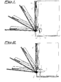
- Fig. 1 is a diagrammatic sectional side view showing a dishwasher according to the invention provided with a standard-size panel;
- Fig. 2 is a view similar to the preceding one of a dishwasher provided with an oversize panel;
- Fig.3 is an enlarged side view of the bottom members of the panel mounting system, with the door in the closed position;
- Fig. 4 is a view similar to the preceding one with the door in the initial opening phase;
- Fig. 5 is a view similar to the preceding one with the door fully open;
- Fig. 6 is an enlarged side view of the top members of the panel mounting system, with the door in the closed position;
- Fig. 7 is a view similar to the preceding one with the door in the initial opening phase; and
- Fig. 8 is a view similar to the preceding one with the door fully open.
-
- With reference to Figs. 1, 3 and 8, there is seen that a dishwasher introduced inside a piece of furniture (only the bottom B of the latter being shown) includes a decorative panel P applied to the door S, the distance between the bottom edge of panel P and the furniture bottom B being covered by a plinth Z. Panel P is applied to the dishwasher through a mounting system including a top sliding coupling R and a bottom parallelogram hinge mounted on an L-shaped support G which is in turn inserted onto a bracket F secured to the dishwasher base M.
- More specifically, panel P carries at its bottom end a bracket H connected through pins C to rods J, K which are in turn connected through pins D at their opposite ends to said support G. The latter is inserted onto bracket F through slide guides (not shown) and secured by screws V whose vertical position can be adjusted within adjustment slots A formed in bracket F. The dotted lines T of Fig.3 illustrate the paths of pins C during the opening movement.
- At the top end, coupling R consists of a pin X, integral with panel P, which slides with bi-directional restraint along a shaped channel Y formed in the top portion of door S. The shape of channel Y is designed to prevent interference between panel P and door S during the opening, due to the relative angle which is formed, and also to keep a proper axial play.
- The simple and effective operation of the present mounting system for panel P is readily understood from the description above with the help of the other figures.
- In the first opening phase from Figs.3 and 6 to Figs.4 and 7, corresponding to about a 30° opening, rods J, K rotate upward around pins D being drawn by bracket H through pins C, while pin X moves along the first portion of channel Y shifting outward to compensate for the different hinging level of door S with respect to panel P.
- Upon complete opening at 90°, pin X is in the top portion of channel Y and panel P has returned to the initial distance from door S, while rods J, K of the bottom hinge have reached a substantially horizontal position.
- From these figures it is clear that in no phase of the movement panel P interferes with plinth Z or moves closer to the dishwasher, whereby there is no problem of interference with the furniture sides. Furthermore, since the whole mounting system is secured to the dishwasher, the latter can be easily pulled out of the furniture for maintenance without requiring the removal of any member.
- Also the adaptation to panels of different heights is simple and readily understood from Fig.2. In this case panel P' has a height greater than the standard panel P, and therefore also plinth Z' is correspondingly lower than plinth Z. However this does not pose any problem since to maintain it flush with the dishwasher top it is sufficient to adjust the position of support G on bracket F, by lowering it along slots A through a distance L equal to the exceeding height of panel P'.
- It is clear that the above-described and illustrated embodiment of the domestic appliance according to the invention is just an example susceptible of various modifications. In particular, the top sliding coupling R may be made in other ways and the same applies to the support/bracket assembly for the bottom hinge as long as the latter is mounted directly on the machine base and positioned so as to keep panel P outside the furniture throughout the opening movement.
Claims (5)
- A built-in domestic appliance with a door (S) hinged along its bottom side and provided with a decorative panel (P), characterized in that said panel (P) is applied to the appliance through a mounting system including a top sliding coupling (R) between the panel (P) and the door (S), and a bottom parallelogram hinge connecting the panel (P) to a support (G) which is in turn carried by a bracket (F) secured to the appliance base (M).
- A built-in domestic appliance according to claim 1, characterized in that the position in height of the support (G) on the bracket (F) is adjustable.
- A built-in domestic appliance according to claim 1 or 2, characterized in that the top coupling (R) consists of a pin (X), integral with the panel (P), which slides with bi-directional restraint along a shaped channel (Y) formed in the top portion of the door (S), the shape of said channel (Y) being designed to prevent interference between the panel (P) and the door (S) during the opening.
- A built-in domestic appliance according to one or more of the preceding claims, characterized in that the panel (P) carries at its bottom end a bracket (H) connected through pins (C) to rods (J, K) which are in turn connected through pins (D) at their opposite ends to an L-shaped support (G).
- A built-in domestic appliance according to one or more of claims 2 to 4, characterized in that the support (G) is mounted onto the bracket (F) by means of screws (V) whose vertical position can be adjusted within adjustment slots (A) formed in the bracket (F).
Priority Applications (4)
| Application Number | Priority Date | Filing Date | Title |
|---|---|---|---|
| AT02425296T ATE258761T1 (en) | 2002-05-15 | 2002-05-15 | BUILT-IN HOUSEHOLD APPLIANCE WITH FACING PLATE ATTACHED TO THE APPLIANCE DOOR |
| ES02425296T ES2215979T3 (en) | 2002-05-15 | 2002-05-15 | ELECTRICAL APPLIANCE INCORPORATED WITH DECORATIVE PANEL APPLIED TO THE DOOR. |
| DE2002600204 DE60200204T2 (en) | 2002-05-15 | 2002-05-15 | Household built-in appliance with front panel arranged on the appliance door |
| EP02425296A EP1364609B1 (en) | 2002-05-15 | 2002-05-15 | Built-in domestic appliance with decorative panel applied to the door |
Applications Claiming Priority (1)
| Application Number | Priority Date | Filing Date | Title |
|---|---|---|---|
| EP02425296A EP1364609B1 (en) | 2002-05-15 | 2002-05-15 | Built-in domestic appliance with decorative panel applied to the door |
Publications (2)
| Publication Number | Publication Date |
|---|---|
| EP1364609A1 true EP1364609A1 (en) | 2003-11-26 |
| EP1364609B1 EP1364609B1 (en) | 2004-02-04 |
Family
ID=29286258
Family Applications (1)
| Application Number | Title | Priority Date | Filing Date |
|---|---|---|---|
| EP02425296A Expired - Lifetime EP1364609B1 (en) | 2002-05-15 | 2002-05-15 | Built-in domestic appliance with decorative panel applied to the door |
Country Status (4)
| Country | Link |
|---|---|
| EP (1) | EP1364609B1 (en) |
| AT (1) | ATE258761T1 (en) |
| DE (1) | DE60200204T2 (en) |
| ES (1) | ES2215979T3 (en) |
Cited By (7)
| Publication number | Priority date | Publication date | Assignee | Title |
|---|---|---|---|---|
| EP1529482B1 (en) * | 2003-11-07 | 2006-12-27 | Bonferraro S.p.A. | Built-in domestic appliance with decorative panel applied to the door |
| EP1875850A1 (en) * | 2006-07-07 | 2008-01-09 | Bonferraro S.p.A. | Built-in domestic appliance with decorative panel applied to the door |
| EP1894509A1 (en) * | 2006-08-31 | 2008-03-05 | Bonferraro S.p.A. | Built-in domestic appliance with decorative panel applied to the door |
| EP2881029A1 (en) | 2013-12-09 | 2015-06-10 | Bonferraro S.p.A. | Built-in domestic appliance with decorative panel applied to the door |
| EP2904955A1 (en) | 2014-02-10 | 2015-08-12 | Bonferraro S.p.A. | Built-in domestic appliance with decorative panel applied to the door |
| EP3081136A1 (en) * | 2015-04-16 | 2016-10-19 | Blaz Zmazek | Household appliance, preferably a built-in dishwasher, with a door and a sliding panel arranged on the door |
| WO2025113260A1 (en) * | 2023-11-27 | 2025-06-05 | 合肥美的电冰箱有限公司 | Door body assembly and refrigeration device |
Families Citing this family (2)
| Publication number | Priority date | Publication date | Assignee | Title |
|---|---|---|---|---|
| EP3478147B1 (en) * | 2016-06-30 | 2021-06-16 | Electrolux Appliances Aktiebolag | Dishwasher |
| KR102607019B1 (en) | 2018-11-15 | 2023-11-29 | 삼성전자주식회사 | Home appliance |
Citations (7)
| Publication number | Priority date | Publication date | Assignee | Title |
|---|---|---|---|---|
| FR2464693A1 (en) * | 1979-09-15 | 1981-03-20 | Bosch Siemens Hausgeraete | Dishwasher with facing panel for built-in systems - has no gap between door and panel with latter moving into base recess when opening door |
| FR2464689A1 (en) * | 1979-09-15 | 1981-03-20 | Bosch Siemens Hausgeraete | Fully-fitted household appliance with door - has one-piece close fitting cover plate with sliding guide at top for relative movement with door |
| US4514021A (en) * | 1982-04-27 | 1985-04-30 | Paul Hettich & Co. | Cabinet with double door consisting of an inner door and an outer door |
| DE3826750A1 (en) * | 1987-08-07 | 1989-02-16 | Balay Sa | CONTROL DEVICE FOR FRONT PARTS OF ELECTRICAL DEVICES |
| EP0420227A1 (en) * | 1989-09-29 | 1991-04-03 | MERLONI ELETTRODOMESTICI S.p.A. | System for the fastening of a front panel to the door of a household appliance |
| EP0520963A1 (en) * | 1991-06-26 | 1992-12-30 | SMEG S.p.A. | A device for slidably-partingly mounting a lining panel on the door of an embedded household appliance |
| US5471709A (en) * | 1993-01-13 | 1995-12-05 | Oreste Lanzani | Built-in electrical appliances, refrigerators in particular |
-
2002
- 2002-05-15 AT AT02425296T patent/ATE258761T1/en not_active IP Right Cessation
- 2002-05-15 ES ES02425296T patent/ES2215979T3/en not_active Expired - Lifetime
- 2002-05-15 DE DE2002600204 patent/DE60200204T2/en not_active Expired - Lifetime
- 2002-05-15 EP EP02425296A patent/EP1364609B1/en not_active Expired - Lifetime
Patent Citations (7)
| Publication number | Priority date | Publication date | Assignee | Title |
|---|---|---|---|---|
| FR2464693A1 (en) * | 1979-09-15 | 1981-03-20 | Bosch Siemens Hausgeraete | Dishwasher with facing panel for built-in systems - has no gap between door and panel with latter moving into base recess when opening door |
| FR2464689A1 (en) * | 1979-09-15 | 1981-03-20 | Bosch Siemens Hausgeraete | Fully-fitted household appliance with door - has one-piece close fitting cover plate with sliding guide at top for relative movement with door |
| US4514021A (en) * | 1982-04-27 | 1985-04-30 | Paul Hettich & Co. | Cabinet with double door consisting of an inner door and an outer door |
| DE3826750A1 (en) * | 1987-08-07 | 1989-02-16 | Balay Sa | CONTROL DEVICE FOR FRONT PARTS OF ELECTRICAL DEVICES |
| EP0420227A1 (en) * | 1989-09-29 | 1991-04-03 | MERLONI ELETTRODOMESTICI S.p.A. | System for the fastening of a front panel to the door of a household appliance |
| EP0520963A1 (en) * | 1991-06-26 | 1992-12-30 | SMEG S.p.A. | A device for slidably-partingly mounting a lining panel on the door of an embedded household appliance |
| US5471709A (en) * | 1993-01-13 | 1995-12-05 | Oreste Lanzani | Built-in electrical appliances, refrigerators in particular |
Cited By (8)
| Publication number | Priority date | Publication date | Assignee | Title |
|---|---|---|---|---|
| EP1529482B1 (en) * | 2003-11-07 | 2006-12-27 | Bonferraro S.p.A. | Built-in domestic appliance with decorative panel applied to the door |
| EP1875850A1 (en) * | 2006-07-07 | 2008-01-09 | Bonferraro S.p.A. | Built-in domestic appliance with decorative panel applied to the door |
| EP1894509A1 (en) * | 2006-08-31 | 2008-03-05 | Bonferraro S.p.A. | Built-in domestic appliance with decorative panel applied to the door |
| EP2881029A1 (en) | 2013-12-09 | 2015-06-10 | Bonferraro S.p.A. | Built-in domestic appliance with decorative panel applied to the door |
| EP2904955A1 (en) | 2014-02-10 | 2015-08-12 | Bonferraro S.p.A. | Built-in domestic appliance with decorative panel applied to the door |
| EP3081136A1 (en) * | 2015-04-16 | 2016-10-19 | Blaz Zmazek | Household appliance, preferably a built-in dishwasher, with a door and a sliding panel arranged on the door |
| WO2025113260A1 (en) * | 2023-11-27 | 2025-06-05 | 合肥美的电冰箱有限公司 | Door body assembly and refrigeration device |
| WO2025113259A1 (en) * | 2023-11-27 | 2025-06-05 | 合肥美的电冰箱有限公司 | Door body device and refrigeration apparatus |
Also Published As
| Publication number | Publication date |
|---|---|
| EP1364609B1 (en) | 2004-02-04 |
| ATE258761T1 (en) | 2004-02-15 |
| DE60200204D1 (en) | 2004-03-11 |
| DE60200204T2 (en) | 2004-11-18 |
| ES2215979T3 (en) | 2004-10-16 |
Similar Documents
| Publication | Publication Date | Title |
|---|---|---|
| US3479104A (en) | Door hinging arrangement in raintight enclosures | |
| EP1364609B1 (en) | Built-in domestic appliance with decorative panel applied to the door | |
| EP1529482B1 (en) | Built-in domestic appliance with decorative panel applied to the door | |
| EP2881029B1 (en) | Built-in domestic appliance with decorative panel applied to the door | |
| CN101677745B (en) | For under-counter mounting system and the correlation technique of dish-washing machine | |
| EP1875850A1 (en) | Built-in domestic appliance with decorative panel applied to the door | |
| US11371715B2 (en) | Cooking appliance comprising a lowerable door, which has a specific retaining spring for a bearing bush | |
| KR102422099B1 (en) | Refrigerator | |
| PL1894509T3 (en) | Built-in domestic appliance with decorative panel applied to the door | |
| CN102099644B (en) | Cover for covering pivot pin of support bracket and household appliance provided with same | |
| GB2079589A (en) | A door for domestic electrical appliances | |
| CN109965709A (en) | A kind of door body structure of household electrical appliance | |
| EP2108729B1 (en) | Electric household appliance featuring a device for fixing an outer panel to the appliance casing | |
| EP1502536B1 (en) | Built-in domestic appliance with front decorative panels | |
| NL9000489A (en) | SWITCH LESSON COMPRISING A LOWER CASING SECTION, LESSON SECTION AND A SUPPORT SECTION. | |
| EP1380250A1 (en) | Built in domestic appliance with front decorative panels | |
| JP3500955B2 (en) | Hanging cabinet | |
| JP2561250Y2 (en) | Equipment front panel structure | |
| EP1591040B1 (en) | Built-in domestic appliance with front decorative panels | |
| US10231595B2 (en) | Appliance with a pin retention feature | |
| AU2022303802B2 (en) | Refrigerator door body assembly, refrigerator, and integrated cupboard | |
| EP1702550B1 (en) | Panel moving system for a built-in appliance or the like, with anti-crushing functionality | |
| US3027216A (en) | Concealable built-in oven | |
| CN109990349A (en) | A kind of mounting structure of range hood | |
| CN208400211U (en) | A kind of embedded display device and vending machine |
Legal Events
| Date | Code | Title | Description |
|---|---|---|---|
| GRAP | Despatch of communication of intention to grant a patent |
Free format text: ORIGINAL CODE: EPIDOSNIGR1 |
|
| PUAI | Public reference made under article 153(3) epc to a published international application that has entered the european phase |
Free format text: ORIGINAL CODE: 0009012 |
|
| 17P | Request for examination filed |
Effective date: 20021202 |
|
| AK | Designated contracting states |
Kind code of ref document: A1 Designated state(s): AT BE CH CY DE DK ES FI FR GB GR IE IT LI LU MC NL PT SE TR |
|
| AX | Request for extension of the european patent |
Extension state: AL LT LV MK RO SI |
|
| GRAS | Grant fee paid |
Free format text: ORIGINAL CODE: EPIDOSNIGR3 |
|
| GRAA | (expected) grant |
Free format text: ORIGINAL CODE: 0009210 |
|
| AK | Designated contracting states |
Kind code of ref document: B1 Designated state(s): AT BE CH CY DE DK ES FI FR GB GR IE IT LI LU MC NL PT SE TR |
|
| AX | Request for extension of the european patent |
Extension state: AL LT LV MK RO SI |
|
| PG25 | Lapsed in a contracting state [announced via postgrant information from national office to epo] |
Ref country code: FI Free format text: LAPSE BECAUSE OF FAILURE TO SUBMIT A TRANSLATION OF THE DESCRIPTION OR TO PAY THE FEE WITHIN THE PRESCRIBED TIME-LIMIT Effective date: 20040204 Ref country code: LI Free format text: LAPSE BECAUSE OF FAILURE TO SUBMIT A TRANSLATION OF THE DESCRIPTION OR TO PAY THE FEE WITHIN THE PRESCRIBED TIME-LIMIT Effective date: 20040204 Ref country code: TR Free format text: LAPSE BECAUSE OF FAILURE TO SUBMIT A TRANSLATION OF THE DESCRIPTION OR TO PAY THE FEE WITHIN THE PRESCRIBED TIME-LIMIT Effective date: 20040204 Ref country code: AT Free format text: LAPSE BECAUSE OF FAILURE TO SUBMIT A TRANSLATION OF THE DESCRIPTION OR TO PAY THE FEE WITHIN THE PRESCRIBED TIME-LIMIT Effective date: 20040204 Ref country code: CY Free format text: LAPSE BECAUSE OF FAILURE TO SUBMIT A TRANSLATION OF THE DESCRIPTION OR TO PAY THE FEE WITHIN THE PRESCRIBED TIME-LIMIT Effective date: 20040204 Ref country code: CH Free format text: LAPSE BECAUSE OF FAILURE TO SUBMIT A TRANSLATION OF THE DESCRIPTION OR TO PAY THE FEE WITHIN THE PRESCRIBED TIME-LIMIT Effective date: 20040204 Ref country code: BE Free format text: LAPSE BECAUSE OF FAILURE TO SUBMIT A TRANSLATION OF THE DESCRIPTION OR TO PAY THE FEE WITHIN THE PRESCRIBED TIME-LIMIT Effective date: 20040204 Ref country code: NL Free format text: LAPSE BECAUSE OF FAILURE TO SUBMIT A TRANSLATION OF THE DESCRIPTION OR TO PAY THE FEE WITHIN THE PRESCRIBED TIME-LIMIT Effective date: 20040204 |
|
| REG | Reference to a national code |
Ref country code: GB Ref legal event code: FG4D |
|
| REG | Reference to a national code |
Ref country code: CH Ref legal event code: EP |
|
| REG | Reference to a national code |
Ref country code: IE Ref legal event code: FG4D |
|
| REF | Corresponds to: |
Ref document number: 60200204 Country of ref document: DE Date of ref document: 20040311 Kind code of ref document: P |
|
| PG25 | Lapsed in a contracting state [announced via postgrant information from national office to epo] |
Ref country code: DK Free format text: LAPSE BECAUSE OF FAILURE TO SUBMIT A TRANSLATION OF THE DESCRIPTION OR TO PAY THE FEE WITHIN THE PRESCRIBED TIME-LIMIT Effective date: 20040504 Ref country code: GR Free format text: LAPSE BECAUSE OF FAILURE TO SUBMIT A TRANSLATION OF THE DESCRIPTION OR TO PAY THE FEE WITHIN THE PRESCRIBED TIME-LIMIT Effective date: 20040504 |
|
| PG25 | Lapsed in a contracting state [announced via postgrant information from national office to epo] |
Ref country code: LU Free format text: LAPSE BECAUSE OF NON-PAYMENT OF DUE FEES Effective date: 20040515 |
|
| PG25 | Lapsed in a contracting state [announced via postgrant information from national office to epo] |
Ref country code: IE Free format text: LAPSE BECAUSE OF NON-PAYMENT OF DUE FEES Effective date: 20040517 |
|
| PG25 | Lapsed in a contracting state [announced via postgrant information from national office to epo] |
Ref country code: MC Free format text: LAPSE BECAUSE OF NON-PAYMENT OF DUE FEES Effective date: 20040531 |
|
| LTIE | Lt: invalidation of european patent or patent extension |
Effective date: 20040204 |
|
| NLV1 | Nl: lapsed or annulled due to failure to fulfill the requirements of art. 29p and 29m of the patents act | ||
| REG | Reference to a national code |
Ref country code: CH Ref legal event code: PL |
|
| AKX | Designation fees paid |
Designated state(s): AT BE CH CY DE DK ES FI FR GB GR IE IT LI LU MC NL PT SE TR |
|
| REG | Reference to a national code |
Ref country code: ES Ref legal event code: FG2A Ref document number: 2215979 Country of ref document: ES Kind code of ref document: T3 |
|
| ET | Fr: translation filed | ||
| PLBE | No opposition filed within time limit |
Free format text: ORIGINAL CODE: 0009261 |
|
| STAA | Information on the status of an ep patent application or granted ep patent |
Free format text: STATUS: NO OPPOSITION FILED WITHIN TIME LIMIT |
|
| 26N | No opposition filed |
Effective date: 20041105 |
|
| REG | Reference to a national code |
Ref country code: IE Ref legal event code: MM4A |
|
| PG25 | Lapsed in a contracting state [announced via postgrant information from national office to epo] |
Ref country code: PT Free format text: LAPSE BECAUSE OF NON-PAYMENT OF DUE FEES Effective date: 20040704 |
|
| PGFP | Annual fee paid to national office [announced via postgrant information from national office to epo] |
Ref country code: ES Payment date: 20100525 Year of fee payment: 9 Ref country code: FR Payment date: 20100611 Year of fee payment: 9 |
|
| PGFP | Annual fee paid to national office [announced via postgrant information from national office to epo] |
Ref country code: SE Payment date: 20100517 Year of fee payment: 9 |
|
| REG | Reference to a national code |
Ref country code: SE Ref legal event code: EUG |
|
| REG | Reference to a national code |
Ref country code: FR Ref legal event code: ST Effective date: 20120131 |
|
| PG25 | Lapsed in a contracting state [announced via postgrant information from national office to epo] |
Ref country code: FR Free format text: LAPSE BECAUSE OF NON-PAYMENT OF DUE FEES Effective date: 20110531 |
|
| PG25 | Lapsed in a contracting state [announced via postgrant information from national office to epo] |
Ref country code: SE Free format text: LAPSE BECAUSE OF NON-PAYMENT OF DUE FEES Effective date: 20110516 |
|
| REG | Reference to a national code |
Ref country code: ES Ref legal event code: FD2A Effective date: 20131030 |
|
| PG25 | Lapsed in a contracting state [announced via postgrant information from national office to epo] |
Ref country code: ES Free format text: LAPSE BECAUSE OF NON-PAYMENT OF DUE FEES Effective date: 20110516 |
|
| PGFP | Annual fee paid to national office [announced via postgrant information from national office to epo] |
Ref country code: GB Payment date: 20200527 Year of fee payment: 19 |
|
| PGFP | Annual fee paid to national office [announced via postgrant information from national office to epo] |
Ref country code: DE Payment date: 20210520 Year of fee payment: 20 Ref country code: IT Payment date: 20210517 Year of fee payment: 20 |
|
| GBPC | Gb: european patent ceased through non-payment of renewal fee |
Effective date: 20210515 |
|
| PG25 | Lapsed in a contracting state [announced via postgrant information from national office to epo] |
Ref country code: GB Free format text: LAPSE BECAUSE OF NON-PAYMENT OF DUE FEES Effective date: 20210515 |
|
| REG | Reference to a national code |
Ref country code: DE Ref legal event code: R071 Ref document number: 60200204 Country of ref document: DE |