EP1364357B1 - Procede et systeme de simulation d'un fil dans des simulations graphiques informatiques - Google Patents
Procede et systeme de simulation d'un fil dans des simulations graphiques informatiques Download PDFInfo
- Publication number
- EP1364357B1 EP1364357B1 EP02716497A EP02716497A EP1364357B1 EP 1364357 B1 EP1364357 B1 EP 1364357B1 EP 02716497 A EP02716497 A EP 02716497A EP 02716497 A EP02716497 A EP 02716497A EP 1364357 B1 EP1364357 B1 EP 1364357B1
- Authority
- EP
- European Patent Office
- Prior art keywords
- segment
- thread
- fixture
- segments
- length
- Prior art date
- Legal status (The legal status is an assumption and is not a legal conclusion. Google has not performed a legal analysis and makes no representation as to the accuracy of the status listed.)
- Expired - Lifetime
Links
Images


Classifications
-
- G—PHYSICS
- G09—EDUCATION; CRYPTOGRAPHY; DISPLAY; ADVERTISING; SEALS
- G09B—EDUCATIONAL OR DEMONSTRATION APPLIANCES; APPLIANCES FOR TEACHING, OR COMMUNICATING WITH, THE BLIND, DEAF OR MUTE; MODELS; PLANETARIA; GLOBES; MAPS; DIAGRAMS
- G09B23/00—Models for scientific, medical, or mathematical purposes, e.g. full-sized devices for demonstration purposes
- G09B23/02—Models for scientific, medical, or mathematical purposes, e.g. full-sized devices for demonstration purposes for mathematics
- G09B23/04—Models for scientific, medical, or mathematical purposes, e.g. full-sized devices for demonstration purposes for mathematics for geometry, trigonometry, projection or perspective
Definitions
- the invention relates to a method for describing a thread as a geometric object in a three dimensional computer graphics system.
- the invention also relates to a computer simulation system employing said method for simulation of systems involving a thread.
- thread will be used throughout this description for convenience, but that it is intended to cover other terms including, but not limited to, suture, wire, cable, rope etc, to the extent that such objects can be described in a computer graphics system in accordance with the method claimed.
- Training for surgical procedures such as sewing together two or more flexible objects, has traditionally been limited to training on human cadavers or animals.
- computer simulators have been developed in order to overcome limitations in traditional training and increase accessibility for health care personnel and students learning surgical skills, as well as experienced surgeons maintaining skills or learning new methods based on development in technology.
- the simulator provides both visual and tactile feedback.
- Visual feedback is provided through a graphics computer driving a stereo display, and a set of optics mimicking a surgical microscope.
- Tactile feedback is provided through an instrument simulating a surgical tool and connected through levers and hinges to servo-motors generating a resistive force along any direction.
- the simulator preferably simulates ocular surgery and displays a model of an eye.
- the model of an eye is produced by first photographing components of the eye, texture mapping the photographs and developing a mathematical model of the eye. There is no description of how surgical threads or sutures could be modeled.
- US-patent 4,321,047 discloses an apparatus for teaching surgical knot tying techniques.
- a flexible tube made of material which simulates various human vessels and ducts is positioned between the arms of a support frame. Inside the tube are spring wires, which are strung under tension between the arms of the support frame.
- a detecting device is connected to the wires, which will generate various kinds of signals when the wires make contact with one another. The student loops a piece of surgical thread around the tube and tightens the loop until wires touch, thus indicating that a certain force has been applied to the tube by the loop. No computer simulation is involved.
- US-patent 5,956,040 discloses a simulation system using computer graphics and a model expression method capable of giving reality to the deformation of a model described by using polygons. Simulation of the behavior of a surgical thread is not described.
- simulation system is not limited to traditional simulators, but also includes systems for numerical simulation of engineering problems involving threads or cables, and also computer graphics workstations for generating a computer graphics representation that e.g. will be played back as a movie or a presentation.
- the invention is based on a data structure that overcomes this bottleneck and allows for rapid description and update of a thread in a computer graphics environment.
- the data structure models the thread as a set of segments connected to each other by fixture points that represent points through which the thread passes.
- the shape of the thread is then described by describing the shape of each segment independently.
- the update of the model is based on passing information from one segment to the next and on moving, adding or deleting fixture points.
- a thread includes the generation of a set of fixture points defining points in space through which the thread passes, and the generation of a set of one or more segments representing the thread between adjacent fixture points.
- Each segment is linked to a pair of fixture points, one at each end of the respective segment, and the geometrical properties of each segment are described.
- segments of the thread that pass through other objects may be described as straight lines between fixture points attached to the surface of the object through which the thread passes, at the respective points where the thread enters or leaves the object.
- Such a segment will henceforth be referred to as an embedded segment.
- Other segments will be referred to as free segments.
- the actual geometrical description of a segment is preferably done as a reference to a curve definition including the numerical description of the shape of the curve. This can be done by defining the segment as an object in an object oriented computer language and including in this object a pointer to an additional object that includes the necessary curve parameters and algorithms for calculating the shape of the curve. These additional objects will be referred to as curve objects.
- the curve instance i.e. the result of the curve shape calculation
- the curve object will then be stored in the curve object, which also includes the necessary functions to calculate this curve instance from information received from the segment object.
- the curve of an embedded segment is a straight line between two fixture points, while the curve of a free segment is calculated based on the position of the fixture points at each end of the segment, gravity vectors, and any other parameters such as flexibility of the thread, tangent of the curve through the fixture point, length of the segment, distance between fixture points etc.
- the fixture points as well as any other geometrical objects are similarly described in an object oriented manner.
- the segments will then include pointers to two fixture points, and the fixture points will include pointers to segments and possibly to an other geometrical object and a variable containing the position of the fixture point.
- the data structure will be stored as data and instructions on a data storage accessible by a processor.
- the processor will be able to, based on the data and the instructions, generate a three dimensional numerical model of the thread and any objects with which the thread interacts and to generate a video representation of this numerical model.
- the simulation system also includes an input interface for receiving control signals representing manipulation of the simulation system and an output interface for sending the generated video representation to a video display.
- the invention also relates to a computer program comprising program instructions for performing the steps of the method.
- a program could be embodied as a computer program product stored on a carrier such as a CD ROM or any other storage medium, or as a propagated signal carrying the information that makes up such a computer program.
- FIG 1 wherein is illustrated the general structure of a computer simulation system according to the invention.
- the system receives input data through an input interface 1.
- This input can come from a keyboard and a mouse, or from more dedicated simulation equipment simulating various tools or controls. It can also come from external storage means or a communications line or a network.
- the system comprises a processor 2 and storage means 3.
- the processor 2 is capable of accessing data and instructions stored on the storage means 3 and operate on the stored data as well as the input data in accordance with the instructions.
- the results of the operations performed on basis of the instructions can be stored on the storage means 3 and/or delivered to output interface 4.
- the results of the operations performed by the processor will most often at least include a video representation of the simulation to be delivered to a display, such as a video monitor or video display goggles, but may also include force feedback or tactile feedback information to be delivered to the input means connected to the input interface.
- the processor 2 of the simulation system may be the CPU of a personal computer or workstation, but it may also be the combination of several processor circuits, including special graphics processors.
- the storage means 3 may in principle include any kind of storage means, such as a hard disk, a CD-ROM, memory circuits etc.
- FIG 2. Here is shown an example of a computer simulation problem to which the invention will be applied.
- the example is drawn from the field of surgical simulation for training of physicians.
- the figure shows a number of geometrical objects with which the thread interacts.
- these objects include a needle 12 attached to the end of the thread and that is being held by a tool 14.
- two flexible tissues 16, 18 which it is the purpose to sew together during the simulation.
- the geometrical description of these additional objects is not part of the invention, and will not be discussed in detail. However, it will be natural to describe the needle 12 as a stiff curve (i.e.
- tissue has a wall like shape, for instance the walls in an artery tube, it can be described by two surfaces, one outer surface 16a, 18a and one inner surface 16b, 18b.
- fixture points are introduced.
- a minimum of six fixture points are required for the modeling of the situation in the figure. It should be noted, though, that they will be introduced during the simulation as is described below with reference to figure 4.
- One fixture point 20 is positioned where the needle is attached to the thread, two fixture points 22, 24 where the thread enters and leaves the first flexible tissue 16, two fixture points 26, 28 where the thread enters and leaves the second flexible tissue 18, and one fixture point at the end of the thread 29.
- Figure 3 a illustrates the data structure for a part of the problem illustrated in figure 2.
- the data structure will be described as objects and pointers in an object oriented paradigm, but it should be noted that the principles of the invention are not limited to this. Other descriptions that allow for a similar exchange of data and calculation of shapes and positions of segments and fixture points, would fall within the scope of the invention. However, it will be understood from the following presentation that an object oriented language is a preferable means of creating the data structure.
- pointers It is not necessary for all objects that are pointed to by another object to include a pointer pointing back at that other object. Also, it is not strictly necessary for two adjacent segments to point at each other, since they will be connected by the fixture point they have in common. However, increasing the number of pointers will reduce the number of searches that must be done when going back and forth through the data structure e.g. when updating the model, something that will facilitate a rapid update during real time simulation. It would be sufficient, however, to include enough pointers to connect all the objects of the model. It is preferred to include at least pointers from all segment objects to connected segments and fixture points and pointers from fixture point objects to connected tissue objects (or whatever other external geometrical objects are included in the simulation).
- the other parts of the model could be constructed according to traditional scene graph theory, as is well known in the art.
- an object representing the tool 14 contains at least one pointer pointing to the needle object 12.
- the needle object 12 contains a pointer pointing to the tool object 14.
- the needle 12 and the first segment 30 of the thread 10 are connected by the first fixture point 20. As illustrated, all these objects may contain pointers pointing to each other.
- the first segment 30 of the thread 10 is a free segment. This segment is connected to the second segment 32 of the thread 10 by a second fixture point 22.
- the second segment 32 is an embedded segment, which again is connected to a free segment 34 by a third fixture point 24. Finally there is another embedded segment 36 connected to the second free segment 34 by a fourth fixture point 26.
- the fixture points 22, 24, 26 that are connecting embedded segments 32, 36 also have pointers pointing to tissue objects 16a, 16b, 18a and vice versa.
- each segment can be contained in the objects themselves, but preferably they are described in separate objects pointed to by the objects they describe.
- each segment whether free or embedded, contains an additional pointer pointing to a geometrical object, or a curve object.
- the objects contain various data and functions and/or references to additional objects containing data and functions.
- the following is a more complete description of the data objects included in the data structure.
- figure 3b shows the general structure of the data model including relations between the various object types. Again it should be noted that it is not necessary to include all the pointers illustrated, as described above.
- Segments can be of different types according to the roles they play in the simulation. The difference between these can be expressed internally in the respective object, or externally, as a result of what other data objects they point to.
- the two fundamental types of segments, embedded segments and free segments, can be of the same object type, but embedded segments will be defined by referring to fixture points that are attached to the surfaces of other objects and by referring to curve objects that define a straight line between these fixture points. However the segment objects are defined, some data is common to all segment objects.
- this includes pointers to two fixture points, one at each end of the segment, pointers to the neighboring segments, if they exist, a pointer to a curve object describing the geometry of the segment, a variable containing the span of the segment, i.e. the distance between the two fixture points at the respective ends of the segment and a variable containing the length of the segment measured along the thread.
- the length is a result of a bookkeeping process, so that the length is increased every time the segment receives more length from an adjacent segment and is decreased every time the segment yields length to an adjacent segment.
- Span is calculated from information received from the respective fixture points.
- the necessary functions for calculating and updating the values of these two variables are preferably included in the segment object as local functions.
- the total length of the thread will be the sum of the length of all the segments. Unless the thread is described with a certain elasticity, the total length of the thread will be constant, but one segment may give up length to an adjacent segment as described below.
- Fixture points can be shared by two segments, and thereby define a topological connection.
- a fixture point may also represent the free end of the thread and only be connected to one segment. Normally, the fixture point will also be connected to an additional object. In our surgery example this additional object will usually represent tissue, but may also represent a surgical tool.
- a fixture point may also be shared by only one segment of the thread and another object, such as a needle or a tool.
- Fixture point objects generally contain the following data: Two pointers pointing to the segments connected by the fixture point, if they are present (only one has to be), pointers to any other geometrical object to which the fixture point is attached, such as a tool, a needle or tissue, and a variable containing the position of the fixture point.
- the fixture point object preferably contains variables containing the tangents of the segments connected by the fixture point. If the two segments are both free, these variables will normally contain the same values, since the thread is considered tangentially continuous. In principle, however, the thread does not have to be tangentially continuous, and normally it will not be in cases where one of the segments is embedded.
- the fixture points define connections that serve to exchange data between objects. If one fixture point is moved, the result may be that other fixture points are moved or that the length of the various segments is changed.
- the fixture points serve as reference points for this exchange of data, which may be calculated recursively or simultaneously. This is described in further detail below.
- Curve objects are objects referred to by segments. For each segment there is one curve object defining the geometrical shape of that segment. This curve object contains the numerical description of the segment, including shape parameters, such as flexibility and gravity vector, and shape calculation algorithms. The curve object receives information from the segment and the fixture points, including span, length and fixture point positions, and based on this input, the shape is calculated and stored in the curve object. The curve object may also contain a choice of algorithms and parameters in order to balance the need for speed and accuracy.
- the curve is implemented as a B-spline, but other formats could be used, such as polygon segments, implicit description, analytical segments, etc.
- the various functions for exchanging length from one object to another and for moving fixture points will preferably be implemented in each object.
- update of the other objects is then done in a recursive manner starting from the fixture point that is moved and progressing along the thread. If the fixture point that is moved is not at one of the ends of the thread, this update will go in both directions of the thread.
- the update should be administered globally however, e.g. by way of an administration algorithm in the fixture point that is moved, in order to ensure that no illegal updates are performed (such as one segment assuming that it receives more length from following segments than actually is available) and so that updates do not travel back and forth along the thread without terminating.
- segment 30 When the first fixture point 20 is moved so far that the span of the first segment 30 exceeds its length, the segment must receive length from other segments.
- the following segment 32 is embedded, and will not change neither span nor length. This means that all the length segment 30 receives from segment 32, segment 32 will immediately receive from segment 34. Segment 30 will only receive enough length for its length to equal its span, in other words it will be tight.
- the curve object pointed to by segment 30 will calculate the new shape of segment 30 as a straight line. Segment 32 will not be changed. Segment 34 will have the same span, but its length will be reduced by the same amount as that with which segment 30 is increased.
- the curve object pointed to by segment 34 will recalculate the shape of segment 34 based on the new length.
- fixture point 24 will reduce the span of segment 34, but since segment 30 is still tight, segment 34 will not slacken. Instead it will give its extra length to segment 32 which immediately passes it on to segment 30.
- the relevant curve objects update the curve shape of the relevant segment. Whether the update is performed as a recursive update along the thread or as a simultaneous update of all the involved objects is a matter of implementation. The important point is to keep the length of the thread constant (unless elasticity is introduced), and to exchange information between objects as a result of the topology defined by the fixture points.
- the data structure allows for more sophisticated update algorithms that include force along the tangents of the segments in the fixture points, and friction. Rules included in the update algorithm can e.g. distribute the applied force into tightening the segment, moving fixture points and overcoming friction (i.e. gaining length from the next segment).
- the operations described above change the parameters of the segments, such as length, span and fixture point position.
- the shape of the individual segments can be calculated independently after these conditions have been established. This is because segments are only influenced by other objects at their respective ends. In other words, the shape of one segment does not influence the shape of any other segment.
- the problem of calculating the shape can be formulated as an optimization problem of minimizing the potential energy of each segment.
- y0 and y1 are given by the positions of the fixture points, and y0' and y1' will normally be defined by either the direction of an adjacent embedded sequence, the direction of an attached tool, or these will be overridden e.g. because of a tangential discontinuity due to the segment being too tight.
- the data structure according to the invention is very flexible and allows easy update also of the topology of the thread, i.e. number of segments and their sequence. Segments can be added or deleted by exchanging information between them and adding or deleting fixture points. For instance, if a tool grabs the thread in the middle of a free segment, a new fixture point would be added, as well as a new segment. The new segment would receive data regarding its length from the original segment, and new segment spans would be calculated. The two segments would be connected by the new fixture point.
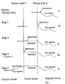
- Figure 4 illustrates an example of the step by step update of the model during a change in the topology of the thread, that is in the ordering and number of segments.
- the example is that of the process of pulling a thread through an other object, such as tissue, in a sewing simulation.
- the example will not consider functions for hit detection between needle and tissue or calculation of deformation of the tissue because of the thread, since these interactions are outside the scope of the invention.
- the update of the data structure will comprise two steps, and these are the same when the thread enters and leaves the tissue.
- FIG 4a Before the thread enters the tissue, the situation is as illustrated in figure 4a, with a thread segment attached to a needle by way of a fixture point.
- a first step when the needle has passed through the tissue wall, as in figure 4b and 4d respectively, the fixture point is moved to the hit point, and the shape of the thread is updated as described above. There is now a gap between the needle and the fixture point.
- a straight (or tight) segment is added from the fixture point at the hit point to the end of the needle. This is illustrated in figure 4c, where the new segment is embedded, and in figure 4e, where the new segment is a free segment.
- the new segment receives length from the other segments and the shape of the respective segments are updated as described above.
Claims (32)
- Procédé pour décrire un fil en tant qu'objet géométrique dans un système graphique informatique tridimensionnel,
caractérisé par les étapes consistant à- générer un ensemble de points de fixation définissant des points dans un espace à travers lequel passe le fil,- générer un ensemble d'un ou de plusieurs segments représentant le fil entre des points de fixation adjacents,- relier chaque segment à une paire de points de fixation, un à chaque extrémité du segment respectif, et- décrire les propriétés géométriques de chaque segment. - Procédé selon la revendication 1,
caractérisé en ce que les segments sont de deux types, des segments encastrés qui décrivent le fil passant à travers un autre objet géométrique, et des segments libres qui décrivent des segments du fil qui peuvent seulement interagir avec d'autres objets géométriques à leurs extrémités. - Procédé selon la revendication 2,
caractérisé en ce que la forme d'un segment encastré est une ligne droite entre des points de fixation à la surface de l'objet géométrique à travers lequel passe le fil. - Procédé selon la revendication 1,
caractérisé en ce que la forme d'un ou de plusieurs segments est calculée en tant qu'approximation de la solution du problème d'optimisation de la minimisation de l'énergie potentielle de chaque segment. - Procédé selon la revendication 4,
caractérisé en ce que l'énergie potentielle d'un segment est exprimée par

où l'intégrale est réalisée sur l'intervalle [0, L], et oùy est le segment de courbe inconnu,y0, y1 sont des positions de frontières dans l'espace tridimensionnel euclidien,y0', y1' sont des tangentes d'unité de frontière dans l'espace tridimensionnel euclidien,L est la longueur du segment,β est la flexibilité du segment,f est une force externe, telle que la pesanteur,R3 est l'espace tridimensionnel euclidien, etH2 est l'espace de distributions de Sobolev avec des dérivés intégrables de manière quadratique d'ordre inférieur ou égal à 2. - Procédé selon la revendication 1,
caractérisé en ce que
la description géométrique d'un quelconque segment est réalisée par l'intermédiaire d'une référence à une définition de courbe incluant la description numérique de la forme du segment respectif. - Procédé selon la revendication 6,
caractérisé en ce que le fil est décrit dans un langage informatique orienté objet de sorte que- chaque point de fixation est décrit comme étant un objet comportant au moins-- deux pointeurs pointant vers les segments adjacents au point de fixation, si présents,-- des pointeurs vers tout autre objet géométrique auquel est relié le point de fixation,-- une variable contenant la position du point de fixation,- chaque segment est décrit comme étant un objet comportant au moins-- deux pointeurs pointant vers les points de fixation à chaque extrémité du segment,-- deux pointeurs pointant vers les segments voisins, si présents,-- un pointeur pointant vers un objet courbe contenant la description numérique de la forme du segment,- chaque définition de courbe est décrite comme étant un objet courbe comportant au moins-- des paramètres de forme,-- des algorithmes de calcul de forme. - Procédé selon la revendication 7,
caractérisé en ce que chaque objet segment comporte également une variable contenant la portée du segment, définie comme étant la distance entre les deux points de fixation pointés, et une variable contenant la longueur du segment, mesurée le long du fil entre les deux points de fixation pointés. - Procédé selon la revendication 7,
caractérisé en ce que chaque objet point de fixation comporte également une variable contenant des valeurs définissant la ou les tangentes des segments pointés par l'objet point de fixation à la position du point du fixation. - Procédé selon la revendication 7,
caractérisé en ce que les paramètres de forme des objets courbe incluent le vecteur de flexibilité et de pesanteur, et que les algorithmes de calcul de forme incluent des fonctions pour effectuer des calculs géométriques sur la base d'informations de longueur et de portée, de positions de points de fixation et de tangentes d'extrémité reçues de l'objet segment correspondant ainsi que desdits paramètres de forme. - Procédé selon la revendication 2,
caractérisé en ce qu'une interaction entre un segment libre quelconque et un autre objet quelconque est décrite en introduisant des points de fixation supplémentaires qui divisent ledit segment libre en deux segments libres. - Procédé selon la revendication 1,
caractérisé en ce qu'un mouvement du fil est décrit en déplaçant un point de fixation et en recalculant la forme et la longueur des segments entre des points de fixation adjacents, en commençant par le point de fixation qui est déplacé et en se déplaçant récursivement le long du fil. - Procédé selon la revendication 1,
caractérisé en ce que la longueur du fil est maintenue constante en effectuant des changements correspondants de la longueur de chaque segment respectif de sorte que tout changement de la longueur d'un segment influence la longueur du segment suivant d'une manière récursive. - Procédé selon la revendication 1,
caractérisé en ce qu'une mise à jour du modèle est effectuée cadre par cadre de sorte que dans une première étape, de nouvelles données sont introduites décrivant un changement du modèle, dans une deuxième étape, le modèle est mis à jour sur la base des nouvelles données, et dans une troisième étape, le modèle mis à jour est visualisé sous la forme d'un cadre dans un système graphique informatique. - Procédé selon l'une quelconque des revendications précédentes,
caractérisé en ce que le fil représente une suture chirurgicale, et les objets géométriques représentent un tissu d'un corps humain dans un système de simulation chirurgical. - Système de simulation pour simuler le comportement d'un fil interagissant avec des objets géométriques dans un système graphique informatique tridimensionnel,
caractérisé en ce que le système comporte- une interface d'entrée pour recevoir des signaux de commande représentant une manipulation du système de simulation,- des moyens de mémorisation dans lesquels sont mémorisés un ensemble d'instructions et un ensemble de données initiales,- un processeur capable, sur la base d'instructions mémorisées sur lesdits moyens de mémorisation, de générer un modèle numérique tridimensionnel dudit fil et desdits objets géométriques, capable de mettre à jour le modèle numérique tridimensionnel sur la base d'instructions supplémentaires sur lesdits moyens de mémorisation et de signaux de commande reçus de l'interface d'entrée, et capable de générer une représentation vidéo du modèle numérique tridimensionnel, et- une interface de sortie pour envoyer ladite représentation vidéo à un écran,dans lequel les données initiales sur lesdits moyens de mémorisation représentent un état initial du modèle numérique tridimensionnel, et les instructions sur lesdits moyens de mémorisation incluent au moins des instructions pour amener le processeur à- générer un ensemble de points de fixation définissant des points dans un espace à travers lequel le fil passe,- générer un ensemble d'un ou de plusieurs segments représentant le fil entre des points de fixation adjacents,- relier chaque segment à une paire de points de fixation, un à chaque extrémité du segment respectif,- décrire les propriétés géométriques de chaque segment,- générer une représentation vidéo du modèle numérique tridimensionnel résultant, et- envoyer la représentation vidéo générée à l'interface de sortie. - Système de simulation selon la revendication 16,
caractérisé en ce que les segments sont de deux types, des segments encastrés qui décrivent le fil passant à travers un autre objet géométrique, et des segments libres qui décrivent des segments du fil qui peuvent seulement interagir avec d'autres objets géométriques à leurs extrémités. - Système de simulation selon la revendication 17,
caractérisé en ce que la forme d'un segment encastré est une ligne droite entre des points de fixation à la surface de l'objet géométrique à travers lequel passe le fil. - Système de simulation selon la revendication 16,
caractérisé en ce que la forme d'un ou de plusieurs segments est calculée comme étant une approximation de la solution du problème d'optimisation de la minimisation de l'énergie potentielle de chaque segment. - Système de simulation selon la revendication 19,
caractérisé en ce que l'énergie potentielle d'un segment est exprimée par

où l'intégrale est réalisée sur l'intervalle [0, L], et oùy est le segment de courbe inconnu,y0, y1 sont des positions de frontières dans l'espace tridimensionnel euclidien,y0', y1' sont des tangentes d'unité de frontière dans l'espace tridimensionnel euclidien,L est la longueur du segment,β est la flexibilité du segment,f est une force externe, telle que la pesanteur,R3 est l'espace tridimensionnel euclidien, etH2 est l'espace de distributions de Sobolev avec des dérivés intégrables de manière quadratique d'ordre inférieur ou égal à 2. - Système de simulation selon la revendication 16,
caractérisé en ce que
la description géométrique d'un quelconque segment est réalisée par l'intermédiaire d'une référence à une définition de courbe incluant la description numérique de la forme du segment respectif. - Système de simulation selon la revendication 21,
caractérisé en ce que les instructions sur lesdits moyens de mémorisation sont dans un langage informatique orienté objet de sorte que :- chaque point de fixation est décrit comme étant un objet comportant au moins-- deux pointeurs pointant vers les segments adjacents au point de fixation, si présents,-- des pointeurs vers tout autre objet géométrique auquel est relié le point de fixation,-- une variable contenant la position du point de fixation,- chaque segment est décrit comme étant un objet comportant au moins-- deux pointeurs pointant vers les points de fixation à chaque extrémité du segment,-- deux pointeurs pointant vers les segments voisins, si présents,-- un pointeur pointant vers un objet courbe contenant la description numérique de la forme du segment,- chaque définition de courbe est décrite comme étant un objet courbe comportant au moins-- des paramètres de forme,-- des algorithmes de calcul de forme. - Système de simulation selon la revendication 22,
caractérisé en ce que chaque objet segment comporte également une variable contenant la portée du segment, définie comme étant la distance entre les deux points de fixation pointés, et une variable contenant la longueur du segment, mesurée le long du fil entre les deux points de fixation pointés. - Système de simulation selon la revendication 22,
caractérisé en ce que chaque objet point de fixation comporte également une variable contenant des valeurs définissant la ou les tangentes des segments pointés par l'objet point de fixation à la position du point du fixation. - Système de simulation selon la revendication 22,
caractérisé en ce que les paramètres de forme des objets courbe incluent un vecteur de flexibilité et de pesanteur, et que les algorithmes de calcul de forme incluent des fonctions pour effectuer des calculs géométriques sur la base d'informations de longueur et de portée, de positions de points de fixation et de tangentes d'extrémité reçues de l'objet segment correspondant ainsi que desdits paramètres de forme. - Système de simulation selon la revendication 17,
caractérisé en ce qu'une interaction entre un segment libre quelconque et un autre objet quelconque est décrite en introduisant des points de fixation supplémentaires qui divisent ledit segment libre en deux segments libres. - Système de simulation selon la revendication 16,
caractérisé en ce qu'un mouvement du fil est décrit en déplaçant un point de fixation sur la base d'informations d'entrée reçues sur l'interface d'entrée et en recalculant la forme et la longueur des segments entre des points de fixation adjacents, en commençant par le point de fixation qui est déplacé et en se déplaçant récursivement le long du fil. - Système de simulation selon la revendication 16,
caractérisé en ce que la longueur du fil est maintenue constante en effectuant des changements correspondants de la longueur de chaque segment respectif de sorte que tout changement de la longueur d'un segment influence la longueur du segment suivant d'une manière récursive. - Système de simulation selon la revendication 16,
caractérisé en ce qu'une mise à jour du modèle est effectuée cadre par cadre de sorte que dans une première étape, de nouvelles données sont introduites décrivant un changement du modèle, dans une deuxième étape, le modèle est mis à jour sur la base des nouvelles données, et dans une troisième étape, le modèle mis à jour est visualisé sous la forme d'un cadre dans un système graphique informatique. - Système de simulation selon l'une quelconque des revendications 16 à 29,
caractérisé en ce que le fil représente une suture chirurgicale, et les objets géométriques représentent un tissu d'un corps humain dans un système de simulation chirurgical. - Produit de programme informatique comportant des instructions de programme mises en oeuvre sur un support lisible par ordinateur pour, lorsque chargées dans un ordinateur, amener l'ordinateur à exécuter les étapes de l'une quelconque des revendications 1 à 15.
- Signal propagé dans lequel sont transportées des informations concernant des instructions de programme dans une forme lisible par ordinateur pour, lorsque chargées dans un ordinateur, amener l'ordinateur à exécuter les étapes selon l'une quelconque des revendications 1 à 15.
Applications Claiming Priority (3)
| Application Number | Priority Date | Filing Date | Title |
|---|---|---|---|
| NO20010127 | 2001-01-08 | ||
| NO20010127A NO313477B1 (no) | 2001-01-08 | 2001-01-08 | Fremgangsmåte og system for å simulere en tråd i datamaskinbaserte grafiske simuleringer |
| PCT/NO2002/000009 WO2002054370A1 (fr) | 2001-01-08 | 2002-01-08 | Procede et systeme de simulation d'un fil dans des simulations graphiques informatiques |
Publications (2)
| Publication Number | Publication Date |
|---|---|
| EP1364357A1 EP1364357A1 (fr) | 2003-11-26 |
| EP1364357B1 true EP1364357B1 (fr) | 2006-03-22 |
Family
ID=19911984
Family Applications (1)
| Application Number | Title | Priority Date | Filing Date |
|---|---|---|---|
| EP02716497A Expired - Lifetime EP1364357B1 (fr) | 2001-01-08 | 2002-01-08 | Procede et systeme de simulation d'un fil dans des simulations graphiques informatiques |
Country Status (6)
| Country | Link |
|---|---|
| US (1) | US7375726B2 (fr) |
| EP (1) | EP1364357B1 (fr) |
| AT (1) | ATE321320T1 (fr) |
| DE (1) | DE60210055T2 (fr) |
| NO (1) | NO313477B1 (fr) |
| WO (1) | WO2002054370A1 (fr) |
Families Citing this family (6)
| Publication number | Priority date | Publication date | Assignee | Title |
|---|---|---|---|---|
| DE102005028103A1 (de) * | 2005-06-16 | 2006-12-21 | Flexilution Gmbh | Verfahren zur Darstellung flexibler längenerstreckter Volumenobjekte |
| US20070239696A1 (en) * | 2006-03-28 | 2007-10-11 | Microsoft Corporation | Interactive relational graphic solutions |
| EP1878823B1 (fr) * | 2006-07-10 | 2019-03-06 | BERNINA International AG | Procédé et dispositif destinés à la représentation de processus de couture |
| WO2010083272A1 (fr) * | 2009-01-15 | 2010-07-22 | Simquest Llc | Simulation interactive de tissu biologique |
| EP2405822A4 (fr) * | 2009-03-12 | 2015-12-23 | Health Research Inc | Méthode et système de formation à la chirurgie très peu invasive |
| US10860900B2 (en) * | 2018-10-30 | 2020-12-08 | International Business Machines Corporation | Transforming source distribution to target distribution using Sobolev Descent |
Family Cites Families (8)
| Publication number | Priority date | Publication date | Assignee | Title |
|---|---|---|---|---|
| US4321047A (en) | 1980-06-05 | 1982-03-23 | Bradley Landis | Simulator and process for teaching surgical knot tying techniques |
| AU8391091A (en) | 1990-09-21 | 1992-04-15 | Medsim, Inc. | System for simulating the physiological response of a living organism |
| JPH06505817A (ja) * | 1990-11-30 | 1994-06-30 | ケンブリッジ アニメーション システムズ リミテッド | 画像合成及び処理 |
| US5766016A (en) | 1994-11-14 | 1998-06-16 | Georgia Tech Research Corporation | Surgical simulator and method for simulating surgical procedure |
| JPH10111958A (ja) * | 1996-10-04 | 1998-04-28 | Olympus Optical Co Ltd | コンピュータグラフィックスを用いたシミュレーションシステム及びシミュレーションシステムにおけるモデル表現方法 |
| AU5464898A (en) | 1996-11-25 | 1998-06-22 | Dadkhah Shahiar | Coronary angioplasty simulator apparatus |
| US6204860B1 (en) * | 1998-07-02 | 2001-03-20 | Silicon Graphics, Inc. | Method and apparatus for geometric model deformation using wires |
| US6707452B1 (en) * | 2000-07-19 | 2004-03-16 | Pixar | Method and apparatus for surface approximation without cracks |
-
2001
- 2001-01-08 NO NO20010127A patent/NO313477B1/no unknown
-
2002
- 2002-01-08 US US10/250,375 patent/US7375726B2/en not_active Expired - Fee Related
- 2002-01-08 EP EP02716497A patent/EP1364357B1/fr not_active Expired - Lifetime
- 2002-01-08 DE DE60210055T patent/DE60210055T2/de not_active Expired - Lifetime
- 2002-01-08 WO PCT/NO2002/000009 patent/WO2002054370A1/fr not_active Application Discontinuation
- 2002-01-08 AT AT02716497T patent/ATE321320T1/de not_active IP Right Cessation
Also Published As
| Publication number | Publication date |
|---|---|
| NO313477B1 (no) | 2002-10-07 |
| ATE321320T1 (de) | 2006-04-15 |
| NO20010127D0 (no) | 2001-01-08 |
| US7375726B2 (en) | 2008-05-20 |
| WO2002054370A1 (fr) | 2002-07-11 |
| DE60210055T2 (de) | 2006-11-09 |
| DE60210055D1 (de) | 2006-05-11 |
| US20040222993A1 (en) | 2004-11-11 |
| EP1364357A1 (fr) | 2003-11-26 |
| NO20010127L (no) | 2002-07-09 |
Similar Documents
| Publication | Publication Date | Title |
|---|---|---|
| Basdogan et al. | Virtual environments for medical training: graphical and haptic simulation of laparoscopic common bile duct exploration | |
| US8485829B2 (en) | System and a method for simulating a manual interventional operation by a user in a medical procedure | |
| Dachille et al. | Haptic sculpting of dynamic surfaces | |
| Raghupathi et al. | An intestinal surgery simulator: real-time collision processing and visualization | |
| US8005659B2 (en) | Simulation of coupled objects | |
| Pan et al. | Graphic and haptic simulation system for virtual laparoscopic rectum surgery | |
| US20090130643A1 (en) | Method for simulating a manual interventional operation by a user in a medical procedure | |
| Xu et al. | Real-time inextensible surgical thread simulation | |
| US20080088578A1 (en) | Flexible object simulator | |
| Mosegaard et al. | GPU accelerated surgical simulators for complex morphology | |
| WO1996016389A1 (fr) | Simulateur d'actes medicaux | |
| Jourdes et al. | Visual haptic feedback for training of robotic suturing | |
| EP1364357B1 (fr) | Procede et systeme de simulation d'un fil dans des simulations graphiques informatiques | |
| US20220151701A1 (en) | Methods for realistic and efficient simulation of moving objects | |
| Radetzky et al. | Visualization and simulation techniques for surgical simulators using actual patient’s data | |
| Hannema | Interaction in virtual reality | |
| Radetzky et al. | Elastodynamic shape modeler: A tool for defining the deformation behavior of virtual tissues | |
| Wang et al. | Haptic rendering for simulation of fine manipulation | |
| Duratti et al. | A real-time simulator for interventional radiology | |
| El-Khalili et al. | Architectural design issues for web-based virtual reality training systems | |
| Eriksson | Haptic Milling Simulation in Six Degrees-of-Freedom: With Application to Surgery in Stiff Tissue | |
| Laycock et al. | The haptic rendering of polygonal models involving deformable tools | |
| Basdogan et al. | 3-DOF haptic rendering | |
| Tai | Research on real-time physics-based deformation for haptic-enabled medical simulation | |
| Eriksson | Three 6-DOF Haptic Algorithms Compared for Use in a Milling Surgery Simulator Prototype |
Legal Events
| Date | Code | Title | Description |
|---|---|---|---|
| PUAI | Public reference made under article 153(3) epc to a published international application that has entered the european phase |
Free format text: ORIGINAL CODE: 0009012 |
|
| 17P | Request for examination filed |
Effective date: 20030806 |
|
| AK | Designated contracting states |
Kind code of ref document: A1 Designated state(s): AT BE CH CY DE DK ES FI FR GB GR IE IT LI LU MC NL PT SE TR |
|
| AX | Request for extension of the european patent |
Extension state: AL LT LV MK RO SI |
|
| GRAP | Despatch of communication of intention to grant a patent |
Free format text: ORIGINAL CODE: EPIDOSNIGR1 |
|
| RIC1 | Information provided on ipc code assigned before grant |
Ipc: 7G 06T 17/00 A |
|
| RIC1 | Information provided on ipc code assigned before grant |
Ipc: 7G 06T 17/00 A |
|
| GRAS | Grant fee paid |
Free format text: ORIGINAL CODE: EPIDOSNIGR3 |
|
| GRAA | (expected) grant |
Free format text: ORIGINAL CODE: 0009210 |
|
| AK | Designated contracting states |
Kind code of ref document: B1 Designated state(s): AT BE CH CY DE DK ES FI FR GB GR IE IT LI LU MC NL PT SE TR |
|
| PG25 | Lapsed in a contracting state [announced via postgrant information from national office to epo] |
Ref country code: IT Free format text: LAPSE BECAUSE OF FAILURE TO SUBMIT A TRANSLATION OF THE DESCRIPTION OR TO PAY THE FEE WITHIN THE PRESCRIBED TIME-LIMIT;WARNING: LAPSES OF ITALIAN PATENTS WITH EFFECTIVE DATE BEFORE 2007 MAY HAVE OCCURRED AT ANY TIME BEFORE 2007. THE CORRECT EFFECTIVE DATE MAY BE DIFFERENT FROM THE ONE RECORDED. Effective date: 20060322 Ref country code: NL Free format text: LAPSE BECAUSE OF FAILURE TO SUBMIT A TRANSLATION OF THE DESCRIPTION OR TO PAY THE FEE WITHIN THE PRESCRIBED TIME-LIMIT Effective date: 20060322 Ref country code: AT Free format text: LAPSE BECAUSE OF FAILURE TO SUBMIT A TRANSLATION OF THE DESCRIPTION OR TO PAY THE FEE WITHIN THE PRESCRIBED TIME-LIMIT Effective date: 20060322 Ref country code: BE Free format text: LAPSE BECAUSE OF FAILURE TO SUBMIT A TRANSLATION OF THE DESCRIPTION OR TO PAY THE FEE WITHIN THE PRESCRIBED TIME-LIMIT Effective date: 20060322 |
|
| REG | Reference to a national code |
Ref country code: GB Ref legal event code: FG4D |
|
| RIN1 | Information on inventor provided before grant (corrected) |
Inventor name: STROM, KYRRE Inventor name: KAASA, JOHANNES Inventor name: ROTNES, JAN, SIGURD Inventor name: WESTGAARD, GEIR |
|
| REG | Reference to a national code |
Ref country code: CH Ref legal event code: EP |
|
| REG | Reference to a national code |
Ref country code: IE Ref legal event code: FG4D |
|
| REF | Corresponds to: |
Ref document number: 60210055 Country of ref document: DE Date of ref document: 20060511 Kind code of ref document: P |
|
| PG25 | Lapsed in a contracting state [announced via postgrant information from national office to epo] |
Ref country code: DK Free format text: LAPSE BECAUSE OF FAILURE TO SUBMIT A TRANSLATION OF THE DESCRIPTION OR TO PAY THE FEE WITHIN THE PRESCRIBED TIME-LIMIT Effective date: 20060622 Ref country code: SE Free format text: LAPSE BECAUSE OF FAILURE TO SUBMIT A TRANSLATION OF THE DESCRIPTION OR TO PAY THE FEE WITHIN THE PRESCRIBED TIME-LIMIT Effective date: 20060622 |
|
| PG25 | Lapsed in a contracting state [announced via postgrant information from national office to epo] |
Ref country code: ES Free format text: LAPSE BECAUSE OF FAILURE TO SUBMIT A TRANSLATION OF THE DESCRIPTION OR TO PAY THE FEE WITHIN THE PRESCRIBED TIME-LIMIT Effective date: 20060703 |
|
| REG | Reference to a national code |
Ref country code: CH Ref legal event code: NV Representative=s name: PATENTANWAELTE SCHAAD, BALASS, MENZL & PARTNER AG |
|
| PG25 | Lapsed in a contracting state [announced via postgrant information from national office to epo] |
Ref country code: PT Free format text: LAPSE BECAUSE OF FAILURE TO SUBMIT A TRANSLATION OF THE DESCRIPTION OR TO PAY THE FEE WITHIN THE PRESCRIBED TIME-LIMIT Effective date: 20060822 |
|
| NLV1 | Nl: lapsed or annulled due to failure to fulfill the requirements of art. 29p and 29m of the patents act | ||
| ET | Fr: translation filed | ||
| PG25 | Lapsed in a contracting state [announced via postgrant information from national office to epo] |
Ref country code: MC Free format text: LAPSE BECAUSE OF NON-PAYMENT OF DUE FEES Effective date: 20070131 |
|
| PLBE | No opposition filed within time limit |
Free format text: ORIGINAL CODE: 0009261 |
|
| STAA | Information on the status of an ep patent application or granted ep patent |
Free format text: STATUS: NO OPPOSITION FILED WITHIN TIME LIMIT |
|
| 26N | No opposition filed |
Effective date: 20061227 |
|
| PG25 | Lapsed in a contracting state [announced via postgrant information from national office to epo] |
Ref country code: GR Free format text: LAPSE BECAUSE OF FAILURE TO SUBMIT A TRANSLATION OF THE DESCRIPTION OR TO PAY THE FEE WITHIN THE PRESCRIBED TIME-LIMIT Effective date: 20060623 |
|
| PG25 | Lapsed in a contracting state [announced via postgrant information from national office to epo] |
Ref country code: FI Free format text: LAPSE BECAUSE OF FAILURE TO SUBMIT A TRANSLATION OF THE DESCRIPTION OR TO PAY THE FEE WITHIN THE PRESCRIBED TIME-LIMIT Effective date: 20060322 |
|
| PGFP | Annual fee paid to national office [announced via postgrant information from national office to epo] |
Ref country code: IE Payment date: 20090123 Year of fee payment: 8 |
|
| PGFP | Annual fee paid to national office [announced via postgrant information from national office to epo] |
Ref country code: CH Payment date: 20090115 Year of fee payment: 8 |
|
| PG25 | Lapsed in a contracting state [announced via postgrant information from national office to epo] |
Ref country code: CY Free format text: LAPSE BECAUSE OF FAILURE TO SUBMIT A TRANSLATION OF THE DESCRIPTION OR TO PAY THE FEE WITHIN THE PRESCRIBED TIME-LIMIT Effective date: 20060322 Ref country code: LU Free format text: LAPSE BECAUSE OF NON-PAYMENT OF DUE FEES Effective date: 20070108 |
|
| PG25 | Lapsed in a contracting state [announced via postgrant information from national office to epo] |
Ref country code: TR Free format text: LAPSE BECAUSE OF FAILURE TO SUBMIT A TRANSLATION OF THE DESCRIPTION OR TO PAY THE FEE WITHIN THE PRESCRIBED TIME-LIMIT Effective date: 20060322 |
|
| REG | Reference to a national code |
Ref country code: CH Ref legal event code: PL |
|
| PG25 | Lapsed in a contracting state [announced via postgrant information from national office to epo] |
Ref country code: CH Free format text: LAPSE BECAUSE OF NON-PAYMENT OF DUE FEES Effective date: 20100131 Ref country code: LI Free format text: LAPSE BECAUSE OF NON-PAYMENT OF DUE FEES Effective date: 20100131 |
|
| PG25 | Lapsed in a contracting state [announced via postgrant information from national office to epo] |
Ref country code: IE Free format text: LAPSE BECAUSE OF NON-PAYMENT OF DUE FEES Effective date: 20100108 |
|
| PGFP | Annual fee paid to national office [announced via postgrant information from national office to epo] |
Ref country code: GB Payment date: 20130122 Year of fee payment: 12 Ref country code: DE Payment date: 20130122 Year of fee payment: 12 Ref country code: FR Payment date: 20130213 Year of fee payment: 12 |
|
| REG | Reference to a national code |
Ref country code: DE Ref legal event code: R119 Ref document number: 60210055 Country of ref document: DE |
|
| GBPC | Gb: european patent ceased through non-payment of renewal fee |
Effective date: 20140108 |
|
| PG25 | Lapsed in a contracting state [announced via postgrant information from national office to epo] |
Ref country code: DE Free format text: LAPSE BECAUSE OF NON-PAYMENT OF DUE FEES Effective date: 20140801 |
|
| REG | Reference to a national code |
Ref country code: FR Ref legal event code: ST Effective date: 20140930 |
|
| REG | Reference to a national code |
Ref country code: DE Ref legal event code: R119 Ref document number: 60210055 Country of ref document: DE Effective date: 20140801 |
|
| PG25 | Lapsed in a contracting state [announced via postgrant information from national office to epo] |
Ref country code: FR Free format text: LAPSE BECAUSE OF NON-PAYMENT OF DUE FEES Effective date: 20140131 Ref country code: GB Free format text: LAPSE BECAUSE OF NON-PAYMENT OF DUE FEES Effective date: 20140108 |