EP1363778B1 - Method and apparatus for direct cylinder printer - Google Patents
Method and apparatus for direct cylinder printer Download PDFInfo
- Publication number
- EP1363778B1 EP1363778B1 EP02704085A EP02704085A EP1363778B1 EP 1363778 B1 EP1363778 B1 EP 1363778B1 EP 02704085 A EP02704085 A EP 02704085A EP 02704085 A EP02704085 A EP 02704085A EP 1363778 B1 EP1363778 B1 EP 1363778B1
- Authority
- EP
- European Patent Office
- Prior art keywords
- substrate
- print engine
- thermal
- thermal foil
- set forth
- Prior art date
- Legal status (The legal status is an assumption and is not a legal conclusion. Google has not performed a legal analysis and makes no representation as to the accuracy of the status listed.)
- Expired - Lifetime
Links
- 238000000034 method Methods 0.000 title claims abstract description 31
- 239000011888 foil Substances 0.000 claims abstract description 123
- 239000000758 substrate Substances 0.000 claims abstract description 88
- 238000007639 printing Methods 0.000 claims abstract description 40
- 230000007246 mechanism Effects 0.000 claims description 37
- 238000010438 heat treatment Methods 0.000 claims description 21
- 238000003825 pressing Methods 0.000 claims 2
- 230000008569 process Effects 0.000 description 9
- CWYNVVGOOAEACU-UHFFFAOYSA-N Fe2+ Chemical group [Fe+2] CWYNVVGOOAEACU-UHFFFAOYSA-N 0.000 description 8
- 238000012546 transfer Methods 0.000 description 8
- 238000013461 design Methods 0.000 description 5
- 238000007651 thermal printing Methods 0.000 description 4
- 239000000853 adhesive Substances 0.000 description 3
- 230000001070 adhesive effect Effects 0.000 description 3
- 230000008859 change Effects 0.000 description 3
- 239000000976 ink Substances 0.000 description 2
- 239000000314 lubricant Substances 0.000 description 2
- 238000012216 screening Methods 0.000 description 2
- 238000004513 sizing Methods 0.000 description 2
- 238000007792 addition Methods 0.000 description 1
- XAGFODPZIPBFFR-UHFFFAOYSA-N aluminium Chemical compound [Al] XAGFODPZIPBFFR-UHFFFAOYSA-N 0.000 description 1
- 229910052782 aluminium Inorganic materials 0.000 description 1
- 239000002216 antistatic agent Substances 0.000 description 1
- 239000000919 ceramic Substances 0.000 description 1
- 230000006835 compression Effects 0.000 description 1
- 238000007906 compression Methods 0.000 description 1
- 239000002537 cosmetic Substances 0.000 description 1
- 238000005034 decoration Methods 0.000 description 1
- 238000005516 engineering process Methods 0.000 description 1
- 239000000945 filler Substances 0.000 description 1
- 239000011521 glass Substances 0.000 description 1
- 231100001261 hazardous Toxicity 0.000 description 1
- 238000013007 heat curing Methods 0.000 description 1
- 238000004519 manufacturing process Methods 0.000 description 1
- 239000000463 material Substances 0.000 description 1
- 238000012986 modification Methods 0.000 description 1
- 230000004048 modification Effects 0.000 description 1
- 238000007649 pad printing Methods 0.000 description 1
- 239000004033 plastic Substances 0.000 description 1
- 229920005989 resin Polymers 0.000 description 1
- 239000011347 resin Substances 0.000 description 1
- 230000000452 restraining effect Effects 0.000 description 1
- 239000000126 substance Substances 0.000 description 1
- 230000001360 synchronised effect Effects 0.000 description 1
Images



Classifications
-
- B—PERFORMING OPERATIONS; TRANSPORTING
- B41—PRINTING; LINING MACHINES; TYPEWRITERS; STAMPS
- B41J—TYPEWRITERS; SELECTIVE PRINTING MECHANISMS, i.e. MECHANISMS PRINTING OTHERWISE THAN FROM A FORME; CORRECTION OF TYPOGRAPHICAL ERRORS
- B41J3/00—Typewriters or selective printing or marking mechanisms characterised by the purpose for which they are constructed
- B41J3/407—Typewriters or selective printing or marking mechanisms characterised by the purpose for which they are constructed for marking on special material
- B41J3/4073—Printing on three-dimensional objects not being in sheet or web form, e.g. spherical or cubic objects
-
- B—PERFORMING OPERATIONS; TRANSPORTING
- B41—PRINTING; LINING MACHINES; TYPEWRITERS; STAMPS
- B41J—TYPEWRITERS; SELECTIVE PRINTING MECHANISMS, i.e. MECHANISMS PRINTING OTHERWISE THAN FROM A FORME; CORRECTION OF TYPOGRAPHICAL ERRORS
- B41J2/00—Typewriters or selective printing mechanisms characterised by the printing or marking process for which they are designed
- B41J2/315—Typewriters or selective printing mechanisms characterised by the printing or marking process for which they are designed characterised by selective application of heat to a heat sensitive printing or impression-transfer material
- B41J2/32—Typewriters or selective printing mechanisms characterised by the printing or marking process for which they are designed characterised by selective application of heat to a heat sensitive printing or impression-transfer material using thermal heads
- B41J2/325—Typewriters or selective printing mechanisms characterised by the printing or marking process for which they are designed characterised by selective application of heat to a heat sensitive printing or impression-transfer material using thermal heads by selective transfer of ink from ink carrier, e.g. from ink ribbon or sheet
-
- B—PERFORMING OPERATIONS; TRANSPORTING
- B41—PRINTING; LINING MACHINES; TYPEWRITERS; STAMPS
- B41P—INDEXING SCHEME RELATING TO PRINTING, LINING MACHINES, TYPEWRITERS, AND TO STAMPS
- B41P2219/00—Printing presses using a heated printing foil
- B41P2219/40—Material or products to be decorated or printed
- B41P2219/43—Three-dimensional articles
Definitions
- the present invention relates to the personalization or decoration of generally cylindrical substrates, and more particularly, to the on-demand digital thermal printing and application of images thereto.
- the printing systems of interest print alphanumeric information, designs and or logos onto a variety of cylindrical objects, such as pens, pencils, cosmetic items, medical devices (e.g., syringe barrels), etc. Accordingly, these systems require that the curved exterior surface of the cylindrical object contact a printing mechanism at all points of printing.
- Silk-screening for example involves the use of a stencil and inking apparatus.
- the cylindrical substrate is brought into rotational contact with the stencil while a squeegee or other device pushes ink through the opposite side of the stencil. While this method of printing produces an adequate image, each change in design requires a replacement stencil.
- Hot stamping cylindrical print systems produce high quality print by means of a curved heated die carrying a specified design. The heated die presses a pigmented or metalized foil against the outer surface of the cylindrical object such that print is formed on areas where the heated die contacts the foil. Any change in design similarly requires a replacement die.
- a digitally-controlled thermal printing system that uses a digital print engine to generate and print selected images onto a cylindrical substrate using a thermal foil. Digital technology allows each applied image to be unique and printed on demand.
- the invention includes a system and apparatus for rotationally supporting and advancing a cylindrical substrate and a supply of thermal foil in synchronous cooperation with a print strobe.
- the thermal foil is used to advance and rotate the cylindrical substrate being printed.
- the thermal foil and substrate are synchronously independently advanced using a variety of advancement means.
- the invention makes use of unique thermal foils designed for application by a digital print engine.
- the thermal foils include a film carrier that resists distortion when subjected to the pressures and relatively high temperatures associated with the digital thermal printing process.
- these thermal foils include a backcoating that comes into contact with the print head.
- the backcoating includes a lubricant that reduces the drag of a thermal print head, thus preventing the thermal foils from sticking to the thermal print head during printing.
- the thermal foils used by the inventive system further include a top coat that resists distortion when subjected to the elevated temperatures (approaching 400 degrees F) associated with the digital transfer process.
- the thermal foil preferably also includes a fast-acting yet aggressive thermally activated adhesive (size coat) that facilitates image transfer from the foil to a substrate.
- a cylinder print system 10 includes a microprocessor 12, a thermal print head assembly 14, a substrate bed assembly 16 and a thermal foil assembly 18 in accordance with the present invention.
- Microprocessor 12 controls the printing process and generates a selected shape to be printed.
- Thermal foil assembly 18 includes a supply of thermal foil 20, which is supplied from a supply roll 22 and collected on a take-up roll 24.
- An advancing mechanism 26 is preferably driven by a motor 30 (e.g., a servomotor or stepper motor), which receives control signals on line 32 from microprocessor 12 and which precisely controls the advancement of thermal foil 20.
- the advancing mechanism 26 drives take-up roll 24 using a belt, gear or other similar means, which in turn advances thermal foil 20.
- microprocessor 12 provides control signals on lines 42 and 44 that direct thermal print head assembly 14, which includes a thermal print head 46 and a pressure mechanism 48 (e.g., a pneumatic actuator), to apply both heat and pressure to thermal foil 20.
- a pressure mechanism 48 e.g., a pneumatic actuator
- the combination of heat and downward pressure cause portions of the foil 20 to detach and adhere to the cylindrical substrate 50.
- a pair of guide rods 34, 36 assist in keeping thermal foil 20 properly tensioned and aligned with print head assembly 14 during foil advancement and printing.
- Guide rods 34, 36 further serve to create a constant media path and to reduce foil creasing and wrinkling. The operation of printing is discussed in more detail with reference to Figs. 3-5 below.
- substrate bed assembly 16 includes a pair of supporting rollers 54, 56.
- supporting rollers 54, 56 are rubber coated to allow adequate friction to drive cylindrical substrate 50 while allowing for some compression to straighten warped or otherwise non-perfectly cylindrical substrates to be printed.
- Bed assembly 16 further includes an optional advancing mechanism 40 for driving supporting roller 56, which in turn rotates cylindrical substrate 50 during the printing process.
- Various diameter substrates may be used by adjusting the gap between print head 46 and bed assembly 16.
- Substrate bed assembly 16 may further include adjustment means for repositioning substrate bed assembly 16 in a direction perpendicular to the path of thermal foil 20. This allows an image to be printed on different portions of a substrate 50.
- motor 30 is operatively connected to both advancing mechanism 40 and advancing mechanism 26 so that motor 30 may synchronously advance thermal foil 20 with the rotation of cylindrical substrate 50 during printing.
- a separate motor (not shown) controlled by microprocessor 12 may also be used to separately drive advancing mechanism 50.
- Advancing mechanism 40 is optional because cylinder print system 10 may employ a frictional force between thermal foil 20 and substrate 50 that is created as thermal foil is advanced past substrate 50, to synchronously advance thermal foil 20 with substrate 50.
- Fig. 2 depicts an alternative method of advancing thermal foil 20.
- This embodiment of the present invention employs a motor driven capstan roller 70, which drives thermal foil 20 through friction.
- Capstan roller 70 is controlled with an advancing mechanism 72, which is driven by motor 30.
- motor 30 receives control signals 80 from microprocessor 12.
- Advancing mechanism 72 uses a belt or gear system to drive capstan roller 70.
- thermal foil 20 is partially wrapped around an outer surface 74 of capstan roller 70 and is held against the outer surface 74 by a pair of guide rods 82, 84.
- guide rods 82, 84 may be adjusted to determine the amount wrap on capstan roller 70.
- Slack created in thermal foil 20 between capstan roller 70 and take-up roll 24 is controlled by an advancing mechanism 90 connected to take-up roll 24.
- Advancing mechanism 90 is preferably driven by motor 30.
- Take-up roll 24 may further include a slip clutch (not shown) or other similar device so that take-up roll 24 may be overdriven with respect to the rate of advance of thermal foil 20.
- an optional advancing mechanism 40 for driving supporting roller 56 and rotating a cylindrical substrate 50 may be included in this embodiment as well. Otherwise, the friction between thermal foil 20 and substrate 50 may be all that is required to synchronously advance thermal foil 20 and substrate 50 with print head 46.
- print head 46 is preferably a true edge, near edge, or convex type thermal print head that includes a plurality of spaced-apart linearly arranged heating elements 100.
- the heating elements 100 are shown arrayed perpendicularly to the direction of travel D of substrate 50 and thermal foil 20.
- Microprocessor 12 provides to print head 46 a plurality of control signals on line 42 that turn on (and off) certain of the individual heating elements 100 needed to produce a desired printed shape.
- a print head glazing (cover) 102 covers the heating elements 100 and when the heating elements are turned on efficiently conveys heat from the heating elements 100 to thermal foil 20.
- the heads ceramic substrate 104 efficiently dissipates the heat to avoid unwanted heat transfer.
- the combination of heat and pressure conveyed from the selectively heated heating elements 100 and the pressure mechanism 48 to thermal foil 20 thermally alters the foil 20, thereby transferring a selected shape to substrate 50 in a line-by-line manner. It is important to note that in the above and below systems that substrate 50 and thermal foil 20 should be synchronously advanced with each print line (strobe) in order to prevent image artifacts caused by stretched images, misses or sticking.
- thermal foil 20 includes a film carrier 110, which pref erably does not distort when subjected to the relatively high temperatures and pressures associated with digital thermal printing.
- the foil 20 further includes a thermally resistive backcoating 112 adhered to the surface of film carrier 110.
- Backcoating 112 includes a lubricant that reduces the drag of print head 40 as it passes over thermal foil 20, and further includes a filler material that smoothes the surface of film carrier 110.
- Backcoating 112 may also contain an anti-static agent, which reduces electrostatic discharge between thermal print head 40 and thermal foil 20.
- thermal foil 20 may include some or all of the following layers attached to film carrier 110; a thermally activated loose yet clean release coat 114 (which may contain wax and or resins), a high temperature top coat 116, an aluminum layer 118 (in metallized foils), a prep coat 120 and a fast-acting yet aggressive thermally activated sizing or adhesive 122.
- the order in which the layers of thermal foil 20 are applied to film carrier 20 is important.
- backcoating 112 requires heat curing, and it is thus important to apply the layer as early as possible to the film carrier 110 in the foil manufacturing process. Otherwise, the heat used to cure the backcoating 112 may change the properties of the other layers of thermal foil 20.
- the release coat 114 and the thermally activated sizing or adhesive 122 are particularly susceptible to heating and may make the thermal foil 20 flaky or loose.
- film carrier 20 has a gauge of less than 0.5 mil., but a thicker gauge film may be used.
- a 0.3 mil. gauge film allows for improved heat transfer between print head 46 and thermal foil 20 and thus allows for quicker dwell times and increased print speeds from cylinder print system 10 than thicker gauge films.
- a decrease in the gauge of film carrier 110 allows for cooler print head 46 temperatures because less heat is required to transfer an image from thermal foil 20 to a substrate.
- lower print head temperatures help protect thermal foil 20 from crazing.
- Fig. 7 depicts an alternate method of transferring an image from thermal foil 20 to cylindrical substrate 50.
- This embodiment employs a two-step transfer process wherein an image is created on thermal foil 20 in a first step and wherein the image is transferred to substrate 50 in a second step.
- an image is produced by applying heat to thermal foil 20 using thermal print assembly 14, however, rather than printing an image directly onto substrate 50, a negative image is printed onto a throwaway medium 130 (e.g., film or paper) using a platen assembly 132, thereby leaving the image to be printed on substrate 50 remaining on thermal foil 20.
- a throwaway medium 130 e.g., film or paper
- Platen assembly 132 includes a platen 134 and an optional advancing mechanism 136.
- Throwaway medium 130 is supplied from a supply roll 140 and collected on take-up roll 142 in much the same way that thermal foil 20 is supplied and collected.
- Throwaway medium 130 is preferably synchronously advanced with thermal foil 20 and platen 134.
- Platen 134 may be rotated similarly to that of substrate 50 in the above-described embodiments, using either friction from throwaway medium 130 or from advancing mechanism 136.
- the print head 46 selectively heats and transfers to throwaway medium 130 the portions of the foil that are not included in the image that is to be transferred to substrate 50. Accordingly, all of these portions that are not part of the image are printed on the throwaway medium.
- thermal foil 20 retaining the image to be transferred is advanced until it is in contact with the surface of substrate 50.
- the image portion of thermal foil 20 encounters the surface of substrate 50, the image is transferred to substrate 50 by a heated rubber stamp device 150.
- the heated rubber stamp device 150 is shown having a flat surface 152, however a curved or deformable surface may be employed, thereby facilitating the transfer of images to tapered or other non-perfectly cylindrical shaped substrates.
- a pressure mechanism 154 such as a pneumatic actuator device, which is controlled by signals 156 received from microprocessor 12, applies pressure to thermal foil 20 where thermal foil 20 contacts substrate 50.
- the temperature of heated rubber stamp device 150 is controlled by signals 158 received from microprocessor 12.
- a pair of supporting rollers 156, 158 supports substrate 50.
- An optional advancing mechanism (not shown) for driving one of the supporting rollers 156, 158 may also be employed for aiding in the rotation of cylindrical substrate 50 during the printing process.
- thermal foil 20 is shown being advanced by an advancing mechanism 160, a capstan type roller such as that described above (not shown) or other advancing means may be used to synchronously advance thermal foil 20 with substrate 50.
- Fig. 8 depicts a cylinder print system 170 having a substrate feeding mechanism 172, which is capable of feeding a plurality of cylindrical substrates 50 to print system 170.
- Cylinder print system 170 includes a microprocessor 12, a thermal print head assembly 14, and a thermal foil assembly 18 in accordance with the above-described embodiments.
- Cylinder print system 170 further includes a substrate advancing system 174 comprising a conveyor mechanism 176 and a substrate positioning mechanism 178.
- a plurality of the substrates 50 are fed from a loader (not shown) onto conveyor mechanism 176, which must stop intermittently to accommodate the printing operation.
- the substrate 50 being printed is lifted out of the conveyor mechanism 176 by positioning the mechanism 178 so as to be contacted by the print head 46.
- the positioning mechanism 178 further comprises a pair or rollers 180, 182 upon which the substrate 50 is free to roll.
- the thermal foil 20 is advanced using a capstan roller 70 and an image generated by the microprocessor 12 is printed onto the substrate 50.
- the substrate feeding mechanism 172 and the substrate advancing mechanism 174 are merely exemplary. It is contemplated that any known method of feeding and positioning a substrate may be used to deliver a plurality of substrates for printing. In addition, any of the above-described methods of advancing the thermal foil 20 or rotating the substrate 50 may be substituted for those methods depicted in Fig. 8 .
- a hollow thermal foil core 180 about which the thermal foil 20 (not shown) is wound, includes a ferrous ring 182 mounted on one end.
- a mounting device 184 for rotatably mounting the foil core 180, includes a core spindle 186 over which the thermal foil core 180 is slidably engaged.
- the mounting device 184 further includes a shaft 188 that is connected to and rotatably controlled by the printing system (i.e., by the advancing mechanism 26).
- the thermal foil core 180 is slidably connected to the mounting device 184 using a series of magnets 190a, 190b that are preferably covered by a smooth cover 192 (e.g. plastic).
- the magnets, 190a, 190b which may be a series of magnets or an individual magnet (e.g., a magnetic ring), releasably adhere to the ferrous ring 182.
- the thermal foil core 180 will rotate in unison with the mounting device 184 until the tension in the thermal foil 20 exceeds the magnetic force between the magnets 190a, 190b and the ferrous ring 182, which will cause the foil core 180 to slip and stop rotating with respect to the mounting device 184.
- This method of attaching the foil core 180 to the mounting device 184 allows the mounting device 184 to be overdriven without damage to the thermal foil 20.
- the thermal foil 20 is advanced through the printing system by the capstan roller 70 ( Fig. 2 )
- the tension in the thermal foil 20 between the capstan roller 70 and the take-up roll 24 will be temporarily reduced.
- the tension in the thermal foil 20 is reduced to the point where the magnetic force between the magnets 190a, 190b and the ferrous ring 182 again exceeds the tension in the thermal foil 20, the overdriven mounting device 184 will cause the foil core 180 to rotate, collecting the slack in the thermal foil 20.
- the tension in the thermal foil 20 will once again increase until the tension exceeds the magnetic force between the magnets 190a, 190b and the ferrous ring 182, which will cause the foil core 180 to slip with respect to the mounting device 184.
- the amount of tension in the thermal foil 20 that will cause the foil core 180 to slip can be adjusted by varying the strength of the magnets 190a, 190b.
- this method of attaching a foil core may also be used simultaneously with or exclusively for mounting the supply roll 22.
- the magnetic force between the magnets 190a, 190b and the ferrous ring 182 acts as a breaking mechanism for the supply roll 22.
- the tension in the thermal foil 20 between the advancing mechanism and the supply roll 22 will increase.
- this tension exceeds the magnetic force between the magnets 190a, 190b and the ferrous ring 182, in this case restraining supply roll 22, an amount of thermal foil 20 will be played out.
- thermal foil core 180 allows the supply of thermal foil 20 to be easily changed or replaced as thermal core 180 can be slipped off core spindle 186 without difficulty and a new supply of thermal foil can be mounted in its place. Also, other similar core mounting systems are contemplated wherein a magnetic force is created by magnets that are part of the core itself and which would adhere to a ferrous mounting device.
Landscapes
- Engineering & Computer Science (AREA)
- Manufacturing & Machinery (AREA)
- Electronic Switches (AREA)
- Discharging, Photosensitive Material Shape In Electrophotography (AREA)
- Accessory Devices And Overall Control Thereof (AREA)
- Printing Methods (AREA)
- Dot-Matrix Printers And Others (AREA)
- Rotary Presses (AREA)
Abstract
Description
- The present invention relates to the personalization or decoration of generally cylindrical substrates, and more particularly, to the on-demand digital thermal printing and application of images thereto.
- The printing systems of interest print alphanumeric information, designs and or logos onto a variety of cylindrical objects, such as pens, pencils, cosmetic items, medical devices (e.g., syringe barrels), etc. Accordingly, these systems require that the curved exterior surface of the cylindrical object contact a printing mechanism at all points of printing.
- In prior known systems, several methods are used to print on cylindrical substrates. These methods include silk screening, hot stamping and pad printing. Unfortunately, these printing methods require runs of several units to be economical since each of these techniques requires a dedicated printing tool such as a screen, die or cliché. The tools, which are unique to the particular information or design to be printed, add significant cost. In addition, the inks, dies and chemicals used with conventional processes are environmentally hazardous, which adds the additional cost of disposal.
- Silk-screening for example involves the use of a stencil and inking apparatus. Typically, the cylindrical substrate is brought into rotational contact with the stencil while a squeegee or other device pushes ink through the opposite side of the stencil. While this method of printing produces an adequate image, each change in design requires a replacement stencil. Hot stamping cylindrical print systems produce high quality print by means of a curved heated die carrying a specified design. The heated die presses a pigmented or metalized foil against the outer surface of the cylindrical object such that print is formed on areas where the heated die contacts the foil. Any change in design similarly requires a replacement die.
- It is therefore an object of the present invention to a method and system for producing and applying images to a generally cylindrical substrate that is adaptable for economically printing short runs of different images.
- To accomplish the foregoing and other objects, features and advantages of the present invention we have provided a digitally-controlled thermal printing system that uses a digital print engine to generate and print selected images onto a cylindrical substrate using a thermal foil. Digital technology allows each applied image to be unique and printed on demand.
- The invention includes a system and apparatus for rotationally supporting and advancing a cylindrical substrate and a supply of thermal foil in synchronous cooperation with a print strobe. In certain embodiments of the present invention the thermal foil is used to advance and rotate the cylindrical substrate being printed. In additional embodiments the thermal foil and substrate are synchronously independently advanced using a variety of advancement means.
- The invention makes use of unique thermal foils designed for application by a digital print engine. Particularly, the thermal foils include a film carrier that resists distortion when subjected to the pressures and relatively high temperatures associated with the digital thermal printing process. More specifically, these thermal foils include a backcoating that comes into contact with the print head. The backcoating includes a lubricant that reduces the drag of a thermal print head, thus preventing the thermal foils from sticking to the thermal print head during printing.
- The thermal foils used by the inventive system further include a top coat that resists distortion when subjected to the elevated temperatures (approaching 400 degrees F) associated with the digital transfer process. The thermal foil preferably also includes a fast-acting yet aggressive thermally activated adhesive (size coat) that facilitates image transfer from the foil to a substrate.
- The invention description below refers to the accompanying drawings, of which:
-
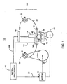
Fig. 1 depicts a partial diagrammatic side view of a cylinder print system in accordance with the invention; -
Fig. 2 depicts a partial diagrammatic side view of a cylinder print system having an alternative method for synchronously advancing a substrate with a print medium; -
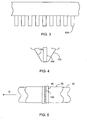
Fig. 3 depicts a partial diagrammatic front view of the thermal print head ofFig. 1 ; -
Fig. 4 depicts a magnified partial view of the thermal print head ofFig. 1 ; -
Fig. 5 depicts a magnified top view of a portion of the thermal print head ofFig. 1 ; -
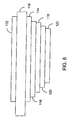
Fig. 6 depicts is a diagrammatic cross-sectional view of a thermal foil according to the present invention -
Fig. 7 depicts a partial diagrammatic side view of a cylinder print system that employs a two step print process; -
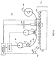
Fig. 8 depicts a partial diagrammatic side view of a cylinder print system having an automatic substrate feed system; -
Fig. 9 depicts a perspective view of a foil core constructed in accordance with the invention; and -
Fig. 10 depicts a mounting device for use with the foil core ofFig. 9 . - Referring to
Fig. 1 , acylinder print system 10 includes amicroprocessor 12, a thermalprint head assembly 14, asubstrate bed assembly 16 and athermal foil assembly 18 in accordance with the present invention.Microprocessor 12 controls the printing process and generates a selected shape to be printed. -
Thermal foil assembly 18 includes a supply ofthermal foil 20, which is supplied from asupply roll 22 and collected on a take-up roll 24. An advancingmechanism 26 is preferably driven by a motor 30 (e.g., a servomotor or stepper motor), which receives control signals online 32 frommicroprocessor 12 and which precisely controls the advancement ofthermal foil 20. The advancingmechanism 26 drives take-up roll 24 using a belt, gear or other similar means, which in turn advancesthermal foil 20. - During the printing process,
microprocessor 12 provides control signals onlines print head assembly 14, which includes athermal print head 46 and a pressure mechanism 48 (e.g., a pneumatic actuator), to apply both heat and pressure tothermal foil 20. The combination of heat and downward pressure cause portions of thefoil 20 to detach and adhere to thecylindrical substrate 50. A pair ofguide rods thermal foil 20 properly tensioned and aligned withprint head assembly 14 during foil advancement and printing.Guide rods Figs. 3-5 below. - In the present embodiment,
substrate bed assembly 16 includes a pair of supportingrollers rollers cylindrical substrate 50 while allowing for some compression to straighten warped or otherwise non-perfectly cylindrical substrates to be printed.Bed assembly 16 further includes an optional advancingmechanism 40 for driving supportingroller 56, which in turn rotatescylindrical substrate 50 during the printing process. Various diameter substrates may be used by adjusting the gap betweenprint head 46 andbed assembly 16.Substrate bed assembly 16 may further include adjustment means for repositioningsubstrate bed assembly 16 in a direction perpendicular to the path ofthermal foil 20. This allows an image to be printed on different portions of asubstrate 50. - In this embodiment,
motor 30 is operatively connected to both advancingmechanism 40 and advancingmechanism 26 so thatmotor 30 may synchronously advancethermal foil 20 with the rotation ofcylindrical substrate 50 during printing. A separate motor (not shown) controlled bymicroprocessor 12 may also be used to separately drive advancingmechanism 50. Advancingmechanism 40 is optional becausecylinder print system 10 may employ a frictional force betweenthermal foil 20 andsubstrate 50 that is created as thermal foil is advancedpast substrate 50, to synchronously advancethermal foil 20 withsubstrate 50. -
Fig. 2 depicts an alternative method of advancingthermal foil 20. This embodiment of the present invention employs a motor drivencapstan roller 70, which drivesthermal foil 20 through friction. Capstanroller 70 is controlled with an advancingmechanism 72, which is driven bymotor 30. As described above,motor 30 receives control signals 80 frommicroprocessor 12. Advancingmechanism 72 uses a belt or gear system to drivecapstan roller 70. - In this embodiment,
thermal foil 20 is partially wrapped around anouter surface 74 ofcapstan roller 70 and is held against theouter surface 74 by a pair ofguide rods capstan roller 70 is advanced, friction betweenthermal foil 20 and theouter surface 74 advancesthermal foil 20. Pull tension is determined by the amount ofthermal foil 20 wrap oncapstan roller 70.Guide rods capstan roller 70. - Slack created in
thermal foil 20 betweencapstan roller 70 and take-up roll 24 is controlled by an advancing mechanism 90 connected to take-up roll 24. Advancing mechanism 90 is preferably driven bymotor 30. Take-up roll 24 may further include a slip clutch (not shown) or other similar device so that take-up roll 24 may be overdriven with respect to the rate of advance ofthermal foil 20. As described above, an optional advancingmechanism 40 for driving supportingroller 56 and rotating acylindrical substrate 50 may be included in this embodiment as well. Otherwise, the friction betweenthermal foil 20 andsubstrate 50 may be all that is required to synchronously advancethermal foil 20 andsubstrate 50 withprint head 46. - Referring to
Figs. 3 through 5 print head 46 is preferably a true edge, near edge, or convex type thermal print head that includes a plurality of spaced-apart linearly arrangedheating elements 100. Theheating elements 100 are shown arrayed perpendicularly to the direction of travel D ofsubstrate 50 andthermal foil 20.Microprocessor 12 provides to print head 46 a plurality of control signals online 42 that turn on (and off) certain of theindividual heating elements 100 needed to produce a desired printed shape. - A print head glazing (cover) 102, preferably glass, covers the
heating elements 100 and when the heating elements are turned on efficiently conveys heat from theheating elements 100 tothermal foil 20. When heatingelements 100 are turned off, the headsceramic substrate 104 efficiently dissipates the heat to avoid unwanted heat transfer. Assubstrate 50 is advanced beneathprint head 46, the combination of heat and pressure conveyed from the selectivelyheated heating elements 100 and thepressure mechanism 48 tothermal foil 20 thermally alters thefoil 20, thereby transferring a selected shape tosubstrate 50 in a line-by-line manner. It is important to note that in the above and below systems thatsubstrate 50 andthermal foil 20 should be synchronously advanced with each print line (strobe) in order to prevent image artifacts caused by stretched images, misses or sticking. - Referring now to
Fig. 6 ,thermal foil 20 includes afilm carrier 110, which pref erably does not distort when subjected to the relatively high temperatures and pressures associated with digital thermal printing. Thefoil 20 further includes a thermallyresistive backcoating 112 adhered to the surface offilm carrier 110.Backcoating 112 includes a lubricant that reduces the drag ofprint head 40 as it passes overthermal foil 20, and further includes a filler material that smoothes the surface offilm carrier 110.Backcoating 112 may also contain an anti-static agent, which reduces electrostatic discharge betweenthermal print head 40 andthermal foil 20. - By way of example,
thermal foil 20 may include some or all of the following layers attached tofilm carrier 110; a thermally activated loose yet clean release coat 114 (which may contain wax and or resins), a high temperaturetop coat 116, an aluminum layer 118 (in metallized foils), aprep coat 120 and a fast-acting yet aggressive thermally activated sizing or adhesive 122. - The order in which the layers of
thermal foil 20 are applied tofilm carrier 20 is important. For example,backcoating 112 requires heat curing, and it is thus important to apply the layer as early as possible to thefilm carrier 110 in the foil manufacturing process. Otherwise, the heat used to cure thebackcoating 112 may change the properties of the other layers ofthermal foil 20. Therelease coat 114 and the thermally activated sizing or adhesive 122 are particularly susceptible to heating and may make thethermal foil 20 flaky or loose. - Preferably,
film carrier 20 has a gauge of less than 0.5 mil., but a thicker gauge film may be used. For example, a 0.3 mil. gauge film allows for improved heat transfer betweenprint head 46 andthermal foil 20 and thus allows for quicker dwell times and increased print speeds fromcylinder print system 10 than thicker gauge films. Additionally, a decrease in the gauge offilm carrier 110 allows forcooler print head 46 temperatures because less heat is required to transfer an image fromthermal foil 20 to a substrate. Furthermore, lower print head temperatures help protectthermal foil 20 from crazing. -
Fig. 7 depicts an alternate method of transferring an image fromthermal foil 20 tocylindrical substrate 50. This embodiment employs a two-step transfer process wherein an image is created onthermal foil 20 in a first step and wherein the image is transferred tosubstrate 50 in a second step. During the first printing step an image is produced by applying heat tothermal foil 20 usingthermal print assembly 14, however, rather than printing an image directly ontosubstrate 50, a negative image is printed onto a throwaway medium 130 (e.g., film or paper) using a platen assembly 132, thereby leaving the image to be printed onsubstrate 50 remaining onthermal foil 20. - Platen assembly 132 includes a
platen 134 and an optional advancingmechanism 136.Throwaway medium 130 is supplied from asupply roll 140 and collected on take-up roll 142 in much the same way thatthermal foil 20 is supplied and collected.Throwaway medium 130 is preferably synchronously advanced withthermal foil 20 andplaten 134.Platen 134 may be rotated similarly to that ofsubstrate 50 in the above-described embodiments, using either friction from throwaway medium 130 or from advancingmechanism 136. In a first printing step theprint head 46 selectively heats and transfers tothrowaway medium 130 the portions of the foil that are not included in the image that is to be transferred tosubstrate 50. Accordingly, all of these portions that are not part of the image are printed on the throwaway medium. - In the second printing step, that part of
thermal foil 20 retaining the image to be transferred is advanced until it is in contact with the surface ofsubstrate 50. When the image portion ofthermal foil 20 encounters the surface ofsubstrate 50, the image is transferred tosubstrate 50 by a heatedrubber stamp device 150. The heatedrubber stamp device 150 is shown having aflat surface 152, however a curved or deformable surface may be employed, thereby facilitating the transfer of images to tapered or other non-perfectly cylindrical shaped substrates. Apressure mechanism 154 such as a pneumatic actuator device, which is controlled bysignals 156 received frommicroprocessor 12, applies pressure tothermal foil 20 wherethermal foil 20contacts substrate 50. Similarly, the temperature of heatedrubber stamp device 150 is controlled bysignals 158 received frommicroprocessor 12. - A pair of supporting
rollers substrate 50. An optional advancing mechanism (not shown) for driving one of the supportingrollers cylindrical substrate 50 during the printing process. Although, in this embodiment,thermal foil 20 is shown being advanced by an advancing mechanism 160, a capstan type roller such as that described above (not shown) or other advancing means may be used to synchronously advancethermal foil 20 withsubstrate 50. -
Fig. 8 depicts acylinder print system 170 having asubstrate feeding mechanism 172, which is capable of feeding a plurality ofcylindrical substrates 50 toprint system 170.Cylinder print system 170 includes amicroprocessor 12, a thermalprint head assembly 14, and athermal foil assembly 18 in accordance with the above-described embodiments.Cylinder print system 170 further includes asubstrate advancing system 174 comprising aconveyor mechanism 176 and a substrate positioning mechanism 178. - In the
substrate feeding mechanism 172, a plurality of thesubstrates 50 are fed from a loader (not shown) ontoconveyor mechanism 176, which must stop intermittently to accommodate the printing operation. During the conveyor dwell, thesubstrate 50 being printed is lifted out of theconveyor mechanism 176 by positioning the mechanism 178 so as to be contacted by theprint head 46. The positioning mechanism 178 further comprises a pair orrollers substrate 50 is free to roll. Upon contact with theprint head 46, thethermal foil 20 is advanced using acapstan roller 70 and an image generated by themicroprocessor 12 is printed onto thesubstrate 50. - It should be noted that the
substrate feeding mechanism 172 and thesubstrate advancing mechanism 174 are merely exemplary. It is contemplated that any known method of feeding and positioning a substrate may be used to deliver a plurality of substrates for printing. In addition, any of the above-described methods of advancing thethermal foil 20 or rotating thesubstrate 50 may be substituted for those methods depicted inFig. 8 . - Referring now to
Figs. 9-10 , we discuss a method and apparatus for mounting the take-up roll 24 (Fig. 1 ) to the printing system. This technique, however, may also be used for mounting the supply roll 22 (Fig. 1 ). As shown inFig. 9 , a hollowthermal foil core 180, about which the thermal foil 20 (not shown) is wound, includes aferrous ring 182 mounted on one end. A mountingdevice 184, for rotatably mounting thefoil core 180, includes acore spindle 186 over which thethermal foil core 180 is slidably engaged. The mountingdevice 184 further includes ashaft 188 that is connected to and rotatably controlled by the printing system (i.e., by the advancing mechanism 26). - The
thermal foil core 180 is slidably connected to the mountingdevice 184 using a series ofmagnets ferrous ring 182. As theshaft 188 is rotated, thethermal foil core 180 will rotate in unison with the mountingdevice 184 until the tension in thethermal foil 20 exceeds the magnetic force between themagnets ferrous ring 182, which will cause thefoil core 180 to slip and stop rotating with respect to the mountingdevice 184. - This method of attaching the
foil core 180 to the mountingdevice 184 allows the mountingdevice 184 to be overdriven without damage to thethermal foil 20. By way of example, if thethermal foil 20 is advanced through the printing system by the capstan roller 70 (Fig. 2 ), the tension in thethermal foil 20 between thecapstan roller 70 and the take-up roll 24 will be temporarily reduced. If the tension in thethermal foil 20 is reduced to the point where the magnetic force between themagnets ferrous ring 182 again exceeds the tension in thethermal foil 20, theoverdriven mounting device 184 will cause thefoil core 180 to rotate, collecting the slack in thethermal foil 20. Once the slack in thethermal foil 20 is collected, the tension in thethermal foil 20 will once again increase until the tension exceeds the magnetic force between themagnets ferrous ring 182, which will cause thefoil core 180 to slip with respect to the mountingdevice 184. The amount of tension in thethermal foil 20 that will cause thefoil core 180 to slip can be adjusted by varying the strength of themagnets - As previously discussed, this method of attaching a foil core may also be used simultaneously with or exclusively for mounting the
supply roll 22. In this embodiment, the magnetic force between themagnets ferrous ring 182 acts as a breaking mechanism for thesupply roll 22. For example, when thethermal foil 20 is advanced through the printing system by any of the above-described methods, the tension in thethermal foil 20 between the advancing mechanism and thesupply roll 22 will increase. When this tension exceeds the magnetic force between themagnets ferrous ring 182, in this case restrainingsupply roll 22, an amount ofthermal foil 20 will be played out. - Additionally, this method of mounting
thermal foil core 180 allows the supply ofthermal foil 20 to be easily changed or replaced asthermal core 180 can be slipped offcore spindle 186 without difficulty and a new supply of thermal foil can be mounted in its place. Also, other similar core mounting systems are contemplated wherein a magnetic force is created by magnets that are part of the core itself and which would adhere to a ferrous mounting device. - The foregoing has been a detailed description of preferred embodiments of the invention. Various modifications and additions can be made without departing from the spirit and scope of the invention.
Claims (20)
- A print system (10, 170) for printing an image onto the exterior surface of a rigid non-flat substrate, comprising:- a digital print engine (14, 46) having a contact surface and a plurality of individually heatable heating elements (100), the digital print engine (14, 46) selectively generating heat to one or more of the plurality of individually heatable heating elements (100);- a thermal foil (20), the thermal foil (20) operatively positioned between the contact surface of the digital print engine (14, 46) and the exterior surface of the rigid non-flat substrate (50);- a pressure mechanism (48) for applying pressure between the contact surface of the digital print engine (14, 46) and the exterior surface of the substrate (50); and- means (16) for rotating the exterior surface of the rigid non-flat substrate (50) with respect to the contact surface of the digital print engine (14, 46) during printing, said means (16) rotating the exterior surface in synchronism with the advancing of the thermal foil (20).
- The system (10, 170) as set forth in claim 1, wherein the heating elements (100) are operatively positioned to transmit heat to different portions of the contact surface.
- The system (10, 170) as set forth in claim 1 or 2, further comprising a microprocessor (12).
- The system (10, 170) as set forth in claim 3, wherein the microprocessor (12) is operatively connected to the digital print engine (14, 46) for selectively controlling one or more of the heating elements (100).
- The system (10, 170) as set forth in claim 3 or 4, wherein the microprocessor (12) is operatively connected to the pressure mechanism (48) such that the microprocessor (12) controls the relative pressure between the contact surface of the digital print engine (14, 46) and the surface of the substrate (50).
- The system (10, 170) as set forth in at least one of the preceding claims, wherein the means (16) for rotating the exterior surface of the rigid non-flat substrate (50) with respect to the contact surface of the digital print engine (14, 46) during printing includes advancing the thermal foil (20) such that a frictional force between the thermal foil (20) and the substrate (50) rotates the substrate (50).
- The system (10, 170) as set forth in at least one of the preceding claims, further comprising a pair of cylindrical support rollers (54, 56) for rotationally supporting the rigid non-flat substrate (50).
- The system (10, 170) as set forth in claim 7, wherein the means (16) for rotating the exterior surface of the rigid non-flat substrate (50) with respect to the contact surface of the digital print engine (14, 46) during printing includes driving one of the cylindrical support rollers (54, 56).
- The system (10, 170) as set forth in claim 6, wherein the thermal foil (20) is advanced using a capstan roller (70).
- The system (10, 170) as set forth in claim 6, wherein the thermal foil (20) is advanced using an overdriven motor (30) and a slip clutch.
- A system (10, 170) as set forth in claim 1, wherein the thermal foil (20) is advanced using a capstan mechanism (70, 82, 84) around which the thermal foil (20) is partially wrapped.
- The system (10, 170) as set forth in at least one of the preceding claims, wherein the image for printing is a selected shape that is personalized.
- The system (10, 170) as set forth in at least one of the claims 1 to 11, wherein the image for printing is a selected shape that is serialized.
- The system (10, 170) as set forth in at least one of the preceding claims, wherein the digital print engine (14, 46) further comprises a thermal print head (46) and the exterior surface is rotated in synchronism with a strobing of the print head (46).
- The system (10, 170) as set forth in at least one of the claims 1 to 13, wherein the digital print engine (14, 46) further comprises a laser based print head (46) and the exterior surface is rotated in synchronism with a pulsing of the print head (46).
- The system (10, 170) as set forth in claims 3, wherein the means (16) for rotating the exterior surface of the rigid non-flat substrate (50) with respect to the contact surface of the digital print engine (14, 46) during printing is controlled by the microprocessor (12).
- The system (10, 170) as set forth in claims 1, wherein the means (16) for rotating the exterior surface of the rigid non-flat substrate (50) with respect to the contact surface of the digital print engine (14, 46) during printing rotates the rigid non-flat substrate (50) also in synchronism with the timing of the controlling of the selective heating of the heating elements (100).
- A print system (10, 170) for printing an image onto the exterior surface of a cylindrical substrate (50) comprising:- a digital print engine (14, 46) for selectively generating heat to one or more of a plurality of individually heatable heating elements (100);- a contact surface operatively positioned with respect to the heating elements (100) such that heat can be transferred through the contact surface;- a platen roller (134);- means (136) for rotating the platen roller (134) with respect to the contact surface of the digital print engine (14, 46) during printing;- a thermal foil (20); the thermal foil (20) operatively positioned between the contact surface of the digital print engine (14, 46) and the platen roller (134);- a throwaway medium (130), the throwaway medium (130) operatively positioned between the thermal foil (20) and the platen roller (134);- a pressure mechanism (154) for applying pressure between the contact surface of the digital print engine and the platen roller;- a microprocessor (12) operatively connected to the digital print engine for selectively controlling one or more of the heating elements (100);- a heatable stamping device (150), wherein the thermal foil (20) is operatively positioned between the heatable stamping device (150) and the cylindrical substrate (50); and- means for rotating the cylindrical substrate with respect to the heatable stamping device during printing, said means rotating the substrate in synchronism with the advancing of the thermal foil.
- A method for transferring a selected shape onto the exterior surface of a cylindrical substrate (50), comprising the steps of:- providing a thermal foil (20);- bringing the exterior surface of the cylindrical substrate (50) into contact with a first surface of the thermal foil (20);- applying heat and pressure to a second surface of the thermal foil (20) using a digital print engine (14, 46) that selectively generates heat to one or more of a plurality of individually heatable heating elements (100) to cause a selected portion of the thermal foil (20) to adhere to the exterior surface of the cylindrical substrate (50) in a specific pattern; and- synchronically rotating the cylindrical substrate (50) and advancing the thermal with respect to the digital print engine (14, 46) during printing.
- The method as set forth in claim 19, wherein the step of rotating the cylindrical substrate (50) also comprises the step of rotating the rigid non-flat substrate (50) also in synchronism with the timing of the controlling of the selective heating of the heating elements (100).
Applications Claiming Priority (3)
| Application Number | Priority Date | Filing Date | Title |
|---|---|---|---|
| US09/765,988 US6570600B2 (en) | 2001-01-19 | 2001-01-19 | Method and apparatus for direct cylinder printer |
| US765988 | 2001-01-19 | ||
| PCT/US2002/000531 WO2002057080A1 (en) | 2001-01-19 | 2002-01-11 | Method and apparatus for direct cylinder printer |
Publications (3)
| Publication Number | Publication Date |
|---|---|
| EP1363778A1 EP1363778A1 (en) | 2003-11-26 |
| EP1363778A4 EP1363778A4 (en) | 2006-12-06 |
| EP1363778B1 true EP1363778B1 (en) | 2008-03-12 |
Family
ID=25075069
Family Applications (1)
| Application Number | Title | Priority Date | Filing Date |
|---|---|---|---|
| EP02704085A Expired - Lifetime EP1363778B1 (en) | 2001-01-19 | 2002-01-11 | Method and apparatus for direct cylinder printer |
Country Status (7)
| Country | Link |
|---|---|
| US (1) | US6570600B2 (en) |
| EP (1) | EP1363778B1 (en) |
| JP (1) | JP2004520965A (en) |
| CN (1) | CN100333906C (en) |
| AT (1) | ATE388823T1 (en) |
| DE (1) | DE60225534T2 (en) |
| WO (1) | WO2002057080A1 (en) |
Cited By (1)
| Publication number | Priority date | Publication date | Assignee | Title |
|---|---|---|---|---|
| TWI745538B (en) * | 2017-02-02 | 2021-11-11 | 美商伊利諾工具工程公司 | Stencil printer having controllable tension device for a stencil wiper assembly, web-material supply module, and method for controlling tension |
Families Citing this family (15)
| Publication number | Priority date | Publication date | Assignee | Title |
|---|---|---|---|---|
| FR2848498A1 (en) * | 2002-12-13 | 2004-06-18 | Stil Or | Method of printing a graphic on a cylindrical or tapered object, uses transfer from printed layer onto thermo-reactive layer formed on surface of object to carry printing |
| US7014284B2 (en) * | 2003-01-16 | 2006-03-21 | Morton William Bill | Ammunition having surface indicia and method of manufacture |
| US20070019049A1 (en) * | 2005-07-22 | 2007-01-25 | National Pen Corp. | Insert molded print product on demand |
| CN101351339B (en) * | 2005-12-29 | 2010-05-19 | 伊利诺斯工具制品有限公司 | Pad printing presses with pad attachment and printing pads |
| US20070207333A1 (en) * | 2006-03-01 | 2007-09-06 | Jerry Surber | Award decoration and method |
| ITUD20070198A1 (en) * | 2007-10-24 | 2009-04-25 | Baccini S P A | POSITIONING DEVICE TO POSITION ONE OR MORE PLATES OF ELECTRONIC CIRCUITS, IN A METAL DEPOSITION UNIT, AND ITS PROCEDURE |
| JP5223317B2 (en) * | 2007-12-05 | 2013-06-26 | ソニー株式会社 | Printer device and laminating method |
| EP2420383B1 (en) * | 2010-08-20 | 2013-10-16 | Agfa Graphics N.V. | Digital system for creating a flexographic printmaster |
| RU2537283C2 (en) * | 2010-09-16 | 2014-12-27 | Бобст Мекс Са | Printing device with use of embossing |
| US8833248B2 (en) * | 2012-05-31 | 2014-09-16 | Illinois Tool Works Inc. | Interior support assembly and method for providing interior support to a target object being printed upon |
| WO2015051215A1 (en) | 2013-10-04 | 2015-04-09 | The Procter & Gamble Company | Process for decorating articles of manufacture |
| WO2016049114A1 (en) * | 2014-09-23 | 2016-03-31 | Impress Systems | Dual mode printer |
| EP4032714B1 (en) | 2014-10-21 | 2023-12-06 | Gen-Probe Incorporated | Method and apparatus for sample transfer comprising a printing module |
| CN110085541B (en) * | 2019-05-15 | 2021-11-02 | 强茂电子(无锡)有限公司 | A method of making a shaft diode |
| JP2024003990A (en) * | 2022-06-28 | 2024-01-16 | 富士フイルムビジネスイノベーション株式会社 | image forming device |
Family Cites Families (11)
| Publication number | Priority date | Publication date | Assignee | Title |
|---|---|---|---|---|
| DE2246797C3 (en) | 1972-09-23 | 1980-10-09 | Agfa-Gevaert Ag, 5090 Leverkusen | Continuous recording of images by means of a liquid jet |
| US4091726A (en) | 1976-11-02 | 1978-05-30 | Joseph E. Podgor, Inc. | Magnetic registration apparatus for silk screen printer |
| US4384518A (en) | 1980-12-01 | 1983-05-24 | Remington Arms Company, Inc. | Dry offset printer for cylindrical objects |
| DE4025712C1 (en) * | 1990-08-14 | 1991-09-12 | Walter Steinhausen Ch Mathis | |
| US5184152A (en) | 1990-12-04 | 1993-02-02 | Sumimoto Electric Interconnect Products, Inc. | Printing apparatus and method for printing on an elongated member such as a tube |
| JPH06236715A (en) * | 1993-02-09 | 1994-08-23 | Nippon Typewriter Co Ltd | Tube printer and tube applying machine to electric wire |
| DE19509984C1 (en) * | 1995-03-18 | 1996-10-02 | Wolfgang Fiwek | Method and device for decorating containers with curved surfaces |
| IL113552A (en) | 1995-04-30 | 2005-09-25 | Hewlett Packard Indigo Bv | Apparatus and method for centerless printing of images particularly on cylindrical objects |
| US5694839A (en) | 1996-09-18 | 1997-12-09 | Trans Tech America, Inc. | Method and apparatus for pad printing cylindrical items |
| SE9703410D0 (en) | 1997-09-22 | 1997-09-22 | Ericsson Telefon Ab L M | Ways to transfer an image to irregular surfaces |
| US6005595A (en) | 1997-09-22 | 1999-12-21 | Illinois Tool Works Inc. | Thermal printer for elongated substrates and method therefor |
-
2001
- 2001-01-19 US US09/765,988 patent/US6570600B2/en not_active Expired - Lifetime
-
2002
- 2002-01-11 DE DE60225534T patent/DE60225534T2/en not_active Expired - Lifetime
- 2002-01-11 AT AT02704085T patent/ATE388823T1/en not_active IP Right Cessation
- 2002-01-11 WO PCT/US2002/000531 patent/WO2002057080A1/en not_active Ceased
- 2002-01-11 JP JP2002557580A patent/JP2004520965A/en active Pending
- 2002-01-11 EP EP02704085A patent/EP1363778B1/en not_active Expired - Lifetime
- 2002-01-11 CN CNB028065239A patent/CN100333906C/en not_active Expired - Fee Related
Cited By (1)
| Publication number | Priority date | Publication date | Assignee | Title |
|---|---|---|---|---|
| TWI745538B (en) * | 2017-02-02 | 2021-11-11 | 美商伊利諾工具工程公司 | Stencil printer having controllable tension device for a stencil wiper assembly, web-material supply module, and method for controlling tension |
Also Published As
| Publication number | Publication date |
|---|---|
| ATE388823T1 (en) | 2008-03-15 |
| DE60225534T2 (en) | 2009-04-02 |
| WO2002057080A1 (en) | 2002-07-25 |
| US6570600B2 (en) | 2003-05-27 |
| EP1363778A4 (en) | 2006-12-06 |
| EP1363778A1 (en) | 2003-11-26 |
| JP2004520965A (en) | 2004-07-15 |
| CN100333906C (en) | 2007-08-29 |
| CN1496307A (en) | 2004-05-12 |
| US20020097315A1 (en) | 2002-07-25 |
| DE60225534D1 (en) | 2008-04-24 |
Similar Documents
| Publication | Publication Date | Title |
|---|---|---|
| US6570600B2 (en) | Method and apparatus for direct cylinder printer | |
| US5318660A (en) | Method and apparatus for generating hot stamped single and multi-color images | |
| CN104284850A (en) | Endless flexible belts for printing systems | |
| JP5116542B2 (en) | Inkjet printing apparatus for fabric | |
| JP3428386B2 (en) | Transfer image forming device | |
| JPH11508523A (en) | Method and apparatus for printing ribbons for gelatin capsule packaging | |
| CN101005953B (en) | Printing method and apparatus | |
| US6388693B1 (en) | Apparatus for printing graphic images on sheet material having an ink web cassette with constant web tension | |
| US4943814A (en) | Computer controllable multi-purpose platen thermal printer | |
| US6031555A (en) | Color printer having a printing film conserving mechanism | |
| JP2009028967A (en) | Thermal transfer printer and thermal transfer method using the same | |
| JP3720410B2 (en) | Printing method in packaging machine | |
| JP2021142693A (en) | Thermal transfer system and thermal transfer method | |
| EP2282945B1 (en) | Rotary wax transfer decorating system | |
| JP2729992B2 (en) | Transfer recording method, transfer recording apparatus and transfer sheet | |
| JP2967303B2 (en) | Film laminating equipment in label printing machine | |
| JPH0368826B2 (en) | ||
| JPH0735104B2 (en) | Film laminating apparatus and method for label printing machine | |
| JP3572693B2 (en) | Transfer mechanism of image forming apparatus | |
| NZ245863A (en) | Coloured or metallic foil printing by passing foil strip and paper/toner web through heated nip rolls | |
| CN100400298C (en) | Printing apparatus | |
| JP2000034043A (en) | Synchronous paper feed mechanism | |
| JP2009034980A (en) | Foil printer | |
| JPH04272838A (en) | Film laminating device in label printing machine | |
| HK40002435B (en) | Endless flexible belt for a printing system |
Legal Events
| Date | Code | Title | Description |
|---|---|---|---|
| PUAI | Public reference made under article 153(3) epc to a published international application that has entered the european phase |
Free format text: ORIGINAL CODE: 0009012 |
|
| 17P | Request for examination filed |
Effective date: 20030819 |
|
| AK | Designated contracting states |
Kind code of ref document: A1 Designated state(s): AT BE CH CY DE DK ES FI FR GB GR IE IT LI LU MC NL PT SE TR |
|
| AX | Request for extension of the european patent |
Extension state: AL LT LV MK RO SI |
|
| RIC1 | Information provided on ipc code assigned before grant |
Ipc: B41F 17/00 20060101AFI20020731BHEP Ipc: B41F 17/20 20060101ALI20061025BHEP Ipc: B41F 17/08 20060101ALI20061025BHEP Ipc: B41J 2/315 20060101ALI20061025BHEP Ipc: B41J 2/325 20060101ALI20061025BHEP Ipc: B41F 17/18 20060101ALI20061025BHEP Ipc: B41J 2/32 20060101ALI20061025BHEP Ipc: B41F 17/10 20060101ALI20061025BHEP Ipc: B41F 16/00 20060101ALI20061025BHEP Ipc: B41F 17/14 20060101ALI20061025BHEP Ipc: B41F 17/22 20060101ALI20061025BHEP |
|
| A4 | Supplementary search report drawn up and despatched |
Effective date: 20061103 |
|
| GRAP | Despatch of communication of intention to grant a patent |
Free format text: ORIGINAL CODE: EPIDOSNIGR1 |
|
| GRAC | Information related to communication of intention to grant a patent modified |
Free format text: ORIGINAL CODE: EPIDOSCIGR1 |
|
| GRAS | Grant fee paid |
Free format text: ORIGINAL CODE: EPIDOSNIGR3 |
|
| GRAA | (expected) grant |
Free format text: ORIGINAL CODE: 0009210 |
|
| AK | Designated contracting states |
Kind code of ref document: B1 Designated state(s): AT BE CH CY DE DK ES FI FR GB GR IE IT LI LU MC NL PT SE TR |
|
| AX | Request for extension of the european patent |
Extension state: AL LT LV MK RO SI |
|
| REG | Reference to a national code |
Ref country code: GB Ref legal event code: FG4D |
|
| REG | Reference to a national code |
Ref country code: CH Ref legal event code: EP |
|
| REG | Reference to a national code |
Ref country code: IE Ref legal event code: FG4D |
|
| REF | Corresponds to: |
Ref document number: 60225534 Country of ref document: DE Date of ref document: 20080424 Kind code of ref document: P |
|
| PG25 | Lapsed in a contracting state [announced via postgrant information from national office to epo] |
Ref country code: FI Free format text: LAPSE BECAUSE OF FAILURE TO SUBMIT A TRANSLATION OF THE DESCRIPTION OR TO PAY THE FEE WITHIN THE PRESCRIBED TIME-LIMIT Effective date: 20080312 |
|
| LTIE | Lt: invalidation of european patent or patent extension |
Effective date: 20080312 |
|
| PG25 | Lapsed in a contracting state [announced via postgrant information from national office to epo] |
Ref country code: AT Free format text: LAPSE BECAUSE OF FAILURE TO SUBMIT A TRANSLATION OF THE DESCRIPTION OR TO PAY THE FEE WITHIN THE PRESCRIBED TIME-LIMIT Effective date: 20080312 |
|
| NLV1 | Nl: lapsed or annulled due to failure to fulfill the requirements of art. 29p and 29m of the patents act | ||
| PG25 | Lapsed in a contracting state [announced via postgrant information from national office to epo] |
Ref country code: BE Free format text: LAPSE BECAUSE OF FAILURE TO SUBMIT A TRANSLATION OF THE DESCRIPTION OR TO PAY THE FEE WITHIN THE PRESCRIBED TIME-LIMIT Effective date: 20080312 |
|
| PG25 | Lapsed in a contracting state [announced via postgrant information from national office to epo] |
Ref country code: ES Free format text: LAPSE BECAUSE OF FAILURE TO SUBMIT A TRANSLATION OF THE DESCRIPTION OR TO PAY THE FEE WITHIN THE PRESCRIBED TIME-LIMIT Effective date: 20080623 Ref country code: PT Free format text: LAPSE BECAUSE OF FAILURE TO SUBMIT A TRANSLATION OF THE DESCRIPTION OR TO PAY THE FEE WITHIN THE PRESCRIBED TIME-LIMIT Effective date: 20080818 Ref country code: SE Free format text: LAPSE BECAUSE OF FAILURE TO SUBMIT A TRANSLATION OF THE DESCRIPTION OR TO PAY THE FEE WITHIN THE PRESCRIBED TIME-LIMIT Effective date: 20080612 |
|
| PG25 | Lapsed in a contracting state [announced via postgrant information from national office to epo] |
Ref country code: NL Free format text: LAPSE BECAUSE OF FAILURE TO SUBMIT A TRANSLATION OF THE DESCRIPTION OR TO PAY THE FEE WITHIN THE PRESCRIBED TIME-LIMIT Effective date: 20080312 |
|
| ET | Fr: translation filed | ||
| PLBE | No opposition filed within time limit |
Free format text: ORIGINAL CODE: 0009261 |
|
| STAA | Information on the status of an ep patent application or granted ep patent |
Free format text: STATUS: NO OPPOSITION FILED WITHIN TIME LIMIT |
|
| PG25 | Lapsed in a contracting state [announced via postgrant information from national office to epo] |
Ref country code: DK Free format text: LAPSE BECAUSE OF FAILURE TO SUBMIT A TRANSLATION OF THE DESCRIPTION OR TO PAY THE FEE WITHIN THE PRESCRIBED TIME-LIMIT Effective date: 20080312 |
|
| 26N | No opposition filed |
Effective date: 20081215 |
|
| PG25 | Lapsed in a contracting state [announced via postgrant information from national office to epo] |
Ref country code: MC Free format text: LAPSE BECAUSE OF NON-PAYMENT OF DUE FEES Effective date: 20090131 |
|
| REG | Reference to a national code |
Ref country code: CH Ref legal event code: PL |
|
| PG25 | Lapsed in a contracting state [announced via postgrant information from national office to epo] |
Ref country code: CY Free format text: LAPSE BECAUSE OF FAILURE TO SUBMIT A TRANSLATION OF THE DESCRIPTION OR TO PAY THE FEE WITHIN THE PRESCRIBED TIME-LIMIT Effective date: 20080312 |
|
| PG25 | Lapsed in a contracting state [announced via postgrant information from national office to epo] |
Ref country code: CH Free format text: LAPSE BECAUSE OF NON-PAYMENT OF DUE FEES Effective date: 20090131 Ref country code: LI Free format text: LAPSE BECAUSE OF NON-PAYMENT OF DUE FEES Effective date: 20090131 |
|
| PG25 | Lapsed in a contracting state [announced via postgrant information from national office to epo] |
Ref country code: IE Free format text: LAPSE BECAUSE OF NON-PAYMENT OF DUE FEES Effective date: 20090112 |
|
| PG25 | Lapsed in a contracting state [announced via postgrant information from national office to epo] |
Ref country code: GR Free format text: LAPSE BECAUSE OF FAILURE TO SUBMIT A TRANSLATION OF THE DESCRIPTION OR TO PAY THE FEE WITHIN THE PRESCRIBED TIME-LIMIT Effective date: 20080613 |
|
| PG25 | Lapsed in a contracting state [announced via postgrant information from national office to epo] |
Ref country code: LU Free format text: LAPSE BECAUSE OF NON-PAYMENT OF DUE FEES Effective date: 20090111 |
|
| PG25 | Lapsed in a contracting state [announced via postgrant information from national office to epo] |
Ref country code: TR Free format text: LAPSE BECAUSE OF FAILURE TO SUBMIT A TRANSLATION OF THE DESCRIPTION OR TO PAY THE FEE WITHIN THE PRESCRIBED TIME-LIMIT Effective date: 20080312 |
|
| REG | Reference to a national code |
Ref country code: FR Ref legal event code: PLFP Year of fee payment: 15 |
|
| REG | Reference to a national code |
Ref country code: FR Ref legal event code: PLFP Year of fee payment: 16 |
|
| REG | Reference to a national code |
Ref country code: FR Ref legal event code: PLFP Year of fee payment: 17 |
|
| PGFP | Annual fee paid to national office [announced via postgrant information from national office to epo] |
Ref country code: IT Payment date: 20190123 Year of fee payment: 18 Ref country code: FR Payment date: 20190125 Year of fee payment: 18 Ref country code: DE Payment date: 20190129 Year of fee payment: 18 Ref country code: GB Payment date: 20190128 Year of fee payment: 18 |
|
| REG | Reference to a national code |
Ref country code: DE Ref legal event code: R119 Ref document number: 60225534 Country of ref document: DE |
|
| GBPC | Gb: european patent ceased through non-payment of renewal fee |
Effective date: 20200111 |
|
| PG25 | Lapsed in a contracting state [announced via postgrant information from national office to epo] |
Ref country code: FR Free format text: LAPSE BECAUSE OF NON-PAYMENT OF DUE FEES Effective date: 20200131 Ref country code: GB Free format text: LAPSE BECAUSE OF NON-PAYMENT OF DUE FEES Effective date: 20200111 Ref country code: DE Free format text: LAPSE BECAUSE OF NON-PAYMENT OF DUE FEES Effective date: 20200801 |
|
| PG25 | Lapsed in a contracting state [announced via postgrant information from national office to epo] |
Ref country code: IT Free format text: LAPSE BECAUSE OF NON-PAYMENT OF DUE FEES Effective date: 20200111 |