EP1363694B1 - Katheteranordnung mit zwei im wesentlichen zirkuläre ballone - Google Patents
Katheteranordnung mit zwei im wesentlichen zirkuläre ballone Download PDFInfo
- Publication number
- EP1363694B1 EP1363694B1 EP02728341A EP02728341A EP1363694B1 EP 1363694 B1 EP1363694 B1 EP 1363694B1 EP 02728341 A EP02728341 A EP 02728341A EP 02728341 A EP02728341 A EP 02728341A EP 1363694 B1 EP1363694 B1 EP 1363694B1
- Authority
- EP
- European Patent Office
- Prior art keywords
- balloon
- catheter
- assembly
- substantially circular
- catheter assembly
- Prior art date
- Legal status (The legal status is an assumption and is not a legal conclusion. Google has not performed a legal analysis and makes no representation as to the accuracy of the status listed.)
- Expired - Lifetime
Links
- 230000009977 dual effect Effects 0.000 title 1
- 238000000034 method Methods 0.000 description 10
- 210000001367 artery Anatomy 0.000 description 5
- 230000003902 lesion Effects 0.000 description 5
- 210000005166 vasculature Anatomy 0.000 description 4
- 230000000712 assembly Effects 0.000 description 3
- 238000000429 assembly Methods 0.000 description 3
- 210000004204 blood vessel Anatomy 0.000 description 3
- 210000004351 coronary vessel Anatomy 0.000 description 3
- 238000002399 angioplasty Methods 0.000 description 2
- HVYWMOMLDIMFJA-DPAQBDIFSA-N cholesterol Chemical compound C1C=C2C[C@@H](O)CC[C@]2(C)[C@@H]2[C@@H]1[C@@H]1CC[C@H]([C@H](C)CCCC(C)C)[C@@]1(C)CC2 HVYWMOMLDIMFJA-DPAQBDIFSA-N 0.000 description 2
- 238000007887 coronary angioplasty Methods 0.000 description 2
- 230000006378 damage Effects 0.000 description 2
- 208000037803 restenosis Diseases 0.000 description 2
- 208000037260 Atherosclerotic Plaque Diseases 0.000 description 1
- 208000031481 Pathologic Constriction Diseases 0.000 description 1
- 208000007536 Thrombosis Diseases 0.000 description 1
- 230000009286 beneficial effect Effects 0.000 description 1
- 230000015572 biosynthetic process Effects 0.000 description 1
- 210000004369 blood Anatomy 0.000 description 1
- 239000008280 blood Substances 0.000 description 1
- 230000017531 blood circulation Effects 0.000 description 1
- 238000007675 cardiac surgery Methods 0.000 description 1
- 235000012000 cholesterol Nutrition 0.000 description 1
- 230000000916 dilatatory effect Effects 0.000 description 1
- 239000012530 fluid Substances 0.000 description 1
- 230000006870 function Effects 0.000 description 1
- 239000007943 implant Substances 0.000 description 1
- HLXZNVUGXRDIFK-UHFFFAOYSA-N nickel titanium Chemical compound [Ti].[Ti].[Ti].[Ti].[Ti].[Ti].[Ti].[Ti].[Ti].[Ti].[Ti].[Ni].[Ni].[Ni].[Ni].[Ni].[Ni].[Ni].[Ni].[Ni].[Ni].[Ni].[Ni].[Ni].[Ni] HLXZNVUGXRDIFK-UHFFFAOYSA-N 0.000 description 1
- 229910001000 nickel titanium Inorganic materials 0.000 description 1
- 238000001556 precipitation Methods 0.000 description 1
- 238000007789 sealing Methods 0.000 description 1
- 238000005728 strengthening Methods 0.000 description 1
- 230000002792 vascular Effects 0.000 description 1
Images

Classifications
-
- A—HUMAN NECESSITIES
- A61—MEDICAL OR VETERINARY SCIENCE; HYGIENE
- A61M—DEVICES FOR INTRODUCING MEDIA INTO, OR ONTO, THE BODY; DEVICES FOR TRANSDUCING BODY MEDIA OR FOR TAKING MEDIA FROM THE BODY; DEVICES FOR PRODUCING OR ENDING SLEEP OR STUPOR
- A61M25/00—Catheters; Hollow probes
- A61M25/10—Balloon catheters
- A61M25/104—Balloon catheters used for angioplasty
-
- A—HUMAN NECESSITIES
- A61—MEDICAL OR VETERINARY SCIENCE; HYGIENE
- A61M—DEVICES FOR INTRODUCING MEDIA INTO, OR ONTO, THE BODY; DEVICES FOR TRANSDUCING BODY MEDIA OR FOR TAKING MEDIA FROM THE BODY; DEVICES FOR PRODUCING OR ENDING SLEEP OR STUPOR
- A61M25/00—Catheters; Hollow probes
- A61M2025/0004—Catheters; Hollow probes having two or more concentrically arranged tubes for forming a concentric catheter system
-
- A—HUMAN NECESSITIES
- A61—MEDICAL OR VETERINARY SCIENCE; HYGIENE
- A61M—DEVICES FOR INTRODUCING MEDIA INTO, OR ONTO, THE BODY; DEVICES FOR TRANSDUCING BODY MEDIA OR FOR TAKING MEDIA FROM THE BODY; DEVICES FOR PRODUCING OR ENDING SLEEP OR STUPOR
- A61M25/00—Catheters; Hollow probes
- A61M25/10—Balloon catheters
- A61M25/1002—Balloon catheters characterised by balloon shape
- A61M2025/1004—Balloons with folds, e.g. folded or multifolded
-
- A—HUMAN NECESSITIES
- A61—MEDICAL OR VETERINARY SCIENCE; HYGIENE
- A61M—DEVICES FOR INTRODUCING MEDIA INTO, OR ONTO, THE BODY; DEVICES FOR TRANSDUCING BODY MEDIA OR FOR TAKING MEDIA FROM THE BODY; DEVICES FOR PRODUCING OR ENDING SLEEP OR STUPOR
- A61M25/00—Catheters; Hollow probes
- A61M25/10—Balloon catheters
- A61M2025/1043—Balloon catheters with special features or adapted for special applications
- A61M2025/1081—Balloon catheters with special features or adapted for special applications having sheaths or the like for covering the balloon but not forming a permanent part of the balloon, e.g. retractable, dissolvable or tearable sheaths
-
- A—HUMAN NECESSITIES
- A61—MEDICAL OR VETERINARY SCIENCE; HYGIENE
- A61M—DEVICES FOR INTRODUCING MEDIA INTO, OR ONTO, THE BODY; DEVICES FOR TRANSDUCING BODY MEDIA OR FOR TAKING MEDIA FROM THE BODY; DEVICES FOR PRODUCING OR ENDING SLEEP OR STUPOR
- A61M25/00—Catheters; Hollow probes
- A61M25/10—Balloon catheters
- A61M25/1011—Multiple balloon catheters
Definitions
- This invention relates to a catheter assembly having at least two balloon catheters which are mounted in a longitudinally overlapping manner in a guide catheter assembly. More specifically, the present invention is directed to a bifurcated stent delivery catheter.
- the catheter of the present invention presents an improvement over known prior bifurcated stent delivery catheters, by providing a catheter assembly with a more circular cross-section than that of known prior bifurcated stent delivery systems.
- PTCA Percutaneous transluminal coronary angioplasty
- the most widely used form of percutaneous coronary angioplasty makes use of a dilatation balloon catheter which is introduced into and advanced through a lumen or body vessel until the distal end thereof is at a desired location in the vasculature.
- the expandable portion of the catheter, or balloon Once in position across a lesion site, the expandable portion of the catheter, or balloon, is inflated to a predetermined size with a fluid at relatively high pressures, to radially compress the atherosclerotic plaque of the lesion against the inside of the artery wall and thereby dilate the lumen of the artery.
- the balloon is then deflated to a small profile so that the dilatation catheter may be withdrawn from the patients vasculature and blood flow resumed through the dilated artery.
- angioplasty procedures of the kind described above, there may be restenosis of the artery, which either necessitates another angioplasty procedure, a surgical by-pass operation, or some method of repairing or strengthening the area.
- a physician can implant an intravascular prosthesis for maintaining vascular patency, such as a stent, inside the artery at the lesion.
- a stent is a generally cylindrical prosthesis introduced via a catheter into a lumen of a body vessel in a configuration having a generally reduced diameter and then expanded to the diameter of the vessel.
- the stent may be self-expanding, such as a NITINOL shape memory stent, or it may be expandable by means of an inflatable portion of the catheter, such as a balloon. In its expanded configuration, the stent supports and reinforces the vessel walls while maintaining the vessel in an open, unobstructed condition.
- a bifurcated stent and/or graft typically comprises a tubular body or trunk and two tubular legs. Examples of bifurcated stents are shown in U.S. Pat. No. 5,723,004 to Dereume et al., U.S. Pat. No. 4,994,071 to MacGregor, and U.S. Pat. No. 5,755,735 to Richter, et al.
- a catheter equipped with an inflation expandable stent particularly a bifurcated stent
- an inflation expandable stent particularly a bifurcated stent
- the profile of a catheter is the outer diameter (OD) of the catheter and the associated stent, as well as, the shape of the catheter's cross-section.
- a catheter may be provided with a reduced profile is by providing the balloon portion of the catheter with a folded arrangement which provides an overall reduction in diameter in at least one axis.
- Many balloon folding configurations are know. For example, U.S. Pat. No. 5,792,172 to Fischell et al., U.S. Pat. No. 6,033,380 to Butaric et al., and U.S. Pat. No. 5,746,745 to Abele et al. each describe various methods of folding the balloon of a balloon catheter.
- a catheter assembly having a profile which is round or substantially circular in cross-section is also desirable, as the round shape largely corresponds to the shape of the various vessels through which the assembly is advanced.
- a substantially circular assembly may be easier to manipulate within the body as the shape of the assembly is less likely to interfere with or be interfered by the vessel walls.
- an individual catheter regardless of the OD, may have a profile which is substantially circular in shape throughout the length of the catheter.
- such "bifurcated catheters” may in fact employ two individual balloon catheters stacked upon one another within a guide catheter assembly. Such a stacked configuration of circular catheters will result in a catheter assembly having an ellipsoid or oval shaped cross-sectional profile, such as is depicted in prior art FIG. 1.
- typical balloon catheters employ inflatable portions or balloons which have wrapping configurations to provide the balloon with a round profile. As may be seen in FIG. 1, the resulting stacked balloons of the two balloon catheters will also have the undesirable oval shaped profile.
- oval shape of prior bifurcated catheters and/or stent delivery systems affects the ease and ability of the dilatation catheter to pass through a guide catheter, the coronary arteries, and across a lesion.
- non-round shapes may be prone to interfere with and even damage vessel walls as the assembly is advanced through and manipulated therein.
- US 5,613,980 discloses a bifurcated catheter system adapted for dilating a preselected stenosed region of a blood vessel having a first branch and a second branch. Both branches are covered by an inflatable balloon having a Y-shape.
- US 6,086,557 discloses a bifurcated venous cannula for draining blood from a patient's heart during cardiac surgery.
- the cannula comprises a main body and a pair of branches extending distally therefrom.
- the branches are biased to extend away from one another by pre-shaped stiffening elements.
- Each branch is provided with an expandable balloon having a circular cross-section for sealing the vena the branch is introduced to.
- the shaft of lack branch is D-shaped in a transverse cross-section.
- US 5,320,605 discloses a multi-wire multi-balloon catheter.
- the catheter comprises a tubular housing, having one axially extending central lumen.
- Two balloon each secured to a shaft are provided in the housing.
- the catheter is used in a multiple balloon dilatation procedure.
- the first balloon is extended distally of the second balloon, and dilated within a preselected site in the body lumen.
- the balloon is evacuated.
- the second balloon is thereafter advanced distally and positioned within the preselected site.
- the second balloon is thereafter dilated.
- the technical problem of the invention is to provide an improved bifurcated stent delivery system.
- the present invention provides for a catheter assembly for use in the treatment of a bifurcated lumen wherein at least a portion of the assembly has a more rounded cross-sectional profile than assemblies previously available.
- This invention provides for a bifurcated catheter assembly wherein at least a portion of the assembly has a substantially circular cross-sectional profile.
- the present invention is directed to a catheter assembly for treatment of a bifurcated lumen.
- the assembly has a proximal end and a distal end with a pair of balloon catheters extending therebetween.
- Each of the balloon catheters employs a shaft and an inflatable portion. At least a portion of the assembly having a circular cross-section.
- the assembly may be more easily manipulated and advanced through the vasculature of the body.
- the assembly may be made to be more readily inserted into a similarly shaped vessel or lumen, than previous assemblies having ellipsoid or oval shaped profiles.
- at least a portion of each of the shafts is provided with a D-shaped profile.
- each of the shafts of the individual balloon catheters has a shape which when held in adjacent proximity to one another provides the shaft portion of the assembly with a substantially circular cross-section.
- the catheter assembly utilizes a novel method for folding and/or arranging the balloons of the individual catheters to provide an assembly which has a more round cross-sectional profile than previously known.
- the inflatable portions or balloons of the balloon catheters may be folded in a complimentary configuration which provides for the desired substantially circular cross-sectional profile.
- the balloons may be folded in a variety of manners which provide at least a portion of the distal end of the assembly with the substantially circular cross-section.
- the assembly may include a stent disposed about at least a portion of the inflatable portions of the catheters.
- the stent may be a standard tubular stent or it may be bifurcated.
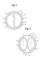
- FIG. 4 does not show an embodiment of the invention.
- the assembly 10 typically will employ a pair of catheters 12 which when assembled together will have an oval or ellipsoid cross-sectional profile 14. While the OD of the assembly may be sufficiently small to allow the assembly to be inserted into an appropriately sized vessel, the oval shape of the assembly presents several problems such as have been described herein above.
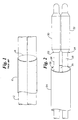
- the present invention avoids the use of an oval shaped catheter assembly by providing an assembly 20 of which at least a portion is substantially circular in cross-sectional profile, such as may be seen in FIG. 2.
- FIG. 2 an embodiment of the invention is shown which includes a catheter assembly, indicated generally at 20, which includes a pair of balloon catheters 22 and 24.
- Each balloon catheter includes a shaft 26 and 28, and an inflatable portion or balloon 30 and 32.
- At least a portion of the catheter 22 and 24 may be contained within a guide catheter 34 which keeps the catheter shafts 26 and 28 in close proximity to one another thereby providing the assembly 20 with a relatively compact profile.
- the guide catheter 34 may be configured to contain the catheters 22 and 24 in the substantially circular lumen 35 which is defined by the guide catheter housing 37.
- the assembly 20 may be configured to have a cross-sectional profile throughout its entire length or a portion thereof.
- the guide catheter is disposed about the catheters 22 and 24 and provides the assembly with a substantially circular shape.
- the catheters 22 and 24 and/or portions thereof may be uniquely configured to provide the desired substantially circular profile, rather than relying exclusively on the circular shape of the housing 37.
- the catheter shafts 26 and 28 may be provided with a D-shaped cross-section having a curved portion 36 and a relatively straight or flat portion 38.
- the unique shape of the shafts 26 and 28 allows them to collectively acquire the substantially circular shape depicted.
- the portion of the assembly 20 corresponding to the catheter shafts 26 and 28 will be provided with a substantially circular cross-sectional profile.
- the D-shaped shafts 26 and 28, positioned in the manner shown, will provide the assembly 20 with the desired rounded profile.
- Figure 4 shows an alternative which does not form part of the present invention. As may be seen in FIG. 4, the shafts 26 and 28 are each provided with an oval shape. When arranged in the manner shown, where the shafts 26 and 28 are held adjacent to one another with the longer axis, indicated by line 40, of each shaft 26 and 28 being substantially parallel, the assembly may be provided with a substantially circular profile.
- oval shaped catheter shafts 26 and 28 do not themselves provide the desired substantially circular profile, when contained within the guide catheter 34, the oval shaped shafts 26 and 28 provide sufficient structural support to the guide catheter 34, that the guide catheter 24 and thus the corresponding portion of the assembly 20 will be substantially circular in profile as shown.
- the present invention is also directed to providing at least a portion of the distal end 50 of an assembly 20 with a substantially circular cross-sectional profile such as may be seen in FIG. 5.
- FIG. 5 a portion of the distal end 50 of a bifurcated catheter assembly 20 is shown.
- the shafts 26 and 28 each respectively have a inflatable portion or balloon 30 and 32 mounted thereon.
- the balloons are typically folded about the shaft to provide a compact profile.
- such individual balloon profiles are round resulting in an oval shaped profile such as may be seen in FIG. 1.
- the balloons 30 and 32 may be folded and positioned in such a manner so as to provide the assembly with the desired substantially circular shaped profile.
- the balloons 30 and 32 are shown prior to deployment. In this configuration the balloons 30 and 32 or at least a portion of each may be held substantially parallel and immediately adjacent to one another.
- the portion of the distal end 50 where the balloons 30 and 32 are immediately adjacent to one another may be characterized as a common portion 52 of the distal end 50.
- the balloons 30 and 32 may be provided with folded configurations which provide the common portion 52 with a substantially circular profile such as is shown.
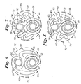
- balloon folding configurations may be utilized to provide the distal end 50 or at least the common portion 52 with the rounded shape desired, three examples of balloon folding techniques are provided herein.
- the first balloon 30 is provided with a pair of wings 60 and 62 which are wrapped partially around the shaft 26 and then extend partially around the second balloon 32.
- the second balloon 32 may have wings 64 and 66 which wrapped in a mutual spiral about the second catheter shaft 28.
- the wings 60 and 62 of the first balloon 30 may be partially wrapped respectively over the wings 64 and 66 of the second balloon 32.
- the second balloon 32 has the same mutually wrapped configuration of wings 64 and 66 as shown in FIG. 6.
- the folds 60 and 62 of the first balloon 30 each comprise an undulating or "zig-zag" shape.
- the wings 60 and 62 respectively extend out to rest upon or contact a wing 64 and 66 of the second balloon 32 in the manner shown.
- the first balloon is equipped with a third balloon fold 63 which is folded atop the shaft 26.
- the remaining folds 60 and 62 are draped over the second balloon 32 in the manner shown.
- the shafts 26 and 28 may have individual profiles which are round, D-shaped, oval or any other configuration desired.
- the assembly 20 may be seen to include a bifurcated stent 70 such as has been previously described.
- the stent 70 also includes a common portion 72 which may be disposed over a portion of both of the balloons 30 and 32, such as may be seen in FIGs 6-8.
- the stent may include one or more arms such as 74 and 76 which are disposed over the distal portions 58 of each balloon 30 and 32.
- the distal portions 58 of the balloons 30 and 32 may also be provided with a substantially-circular cross section even when carrying a stent 70.
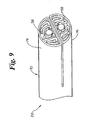
- FIG. 9 an embodiment of the invention is shown where the arms 74 and 76 of the stent 70 are each provided with a D-shaped profile, similar to the D-shaped profile of the catheter shafts depicted in FIG. 3 and described above.
- the balloons 30 and 32 may be respectively folded in such a manner as to provide a the distal portions 58 of each balloon 30 and 32 with a D-shaped or hemispherical profile such is shown in FIG. 9.
- the arms 74 and 76 of the stent as well as the balloons 30 and 32 may be constructed such that in the unexpanded state they have the D-shaped profile shown, but when expanded they may be substantially round or circular in profile.
- the balloons 30 and 32 are configured to have a round profile when in the inflated state. The force exerted by the expanded balloons on the stent arms 74 and 76 will cause the arms 74 and 76 to assume the shape of the respective balloons 30 and 32.
Landscapes
- Health & Medical Sciences (AREA)
- Heart & Thoracic Surgery (AREA)
- Life Sciences & Earth Sciences (AREA)
- Anesthesiology (AREA)
- Child & Adolescent Psychology (AREA)
- Biophysics (AREA)
- Pulmonology (AREA)
- Engineering & Computer Science (AREA)
- Vascular Medicine (AREA)
- Biomedical Technology (AREA)
- Hematology (AREA)
- Animal Behavior & Ethology (AREA)
- General Health & Medical Sciences (AREA)
- Public Health (AREA)
- Veterinary Medicine (AREA)
- Media Introduction/Drainage Providing Device (AREA)
Claims (11)
- Katheteranordnung zur Behandlung eines zweigeteilten Hohlraums, wobei die Anordnung ein proximales Ende und ein distales Ende aufweist, wobei die Anordnung Folgendes umfasst:einen ersten Ballonkatheter (22), der einen ersten Katheterschaft (26) und einen ersten Ballon (30) aufweist, der darauf angebracht ist;einen zweiten Ballonkatheter (24), der einen zweiten Katheterschaft (28) und einen zweiten Ballon (32) aufweist, der darauf angebracht ist;ein Gehäuse (34), das um mindestens einen Abschnitt des ersten Ballonkatheters (22) und mindestens einen Abschnitt des zweiten Ballonkatheters (24) abgeordnet ist; undwobei der erste und zweite Ballonkatheter vom proximalen Ende zum distalen Ende der Anordnung verlaufen, der erste Ballon und der zweite Ballon am distalen Ende der Anordnung angeordnet sind, mindestens ein Abschnitt der Anordnung einen im Wesentlichen zirkulären Querschnitt aufweist, der Abschnitt des ersten Ballonkatheters und der Abschnitt des zweiten Ballonkatheters im Wesentlichen parallel zueinander angeordnet sind, dadurch gekennzeichnet, dassder Abschnitt des ersten Katheterschafts und der Abschnitt des zweiten Katheterschafts im Querschnitt jeweils im Wesentlichen D-förmig sind, wobei der erste Katheterschaft einen ersten gebogenen Abschnitt und einen ersten geraden Abschnitt aufweist und der zweite Katheterschaft einen zweiten gebogenen Abschnitt und einen zweiten abgeflachten Abschnitt aufweist, wobei der erste abgeflachte Abschnitt unmittelbar angrenzend an den zweiten abgeflachten Abschnitt angeordnet ist.
- Katheteranordnung nach Anspruch 1, wobei der mindestens eine Abschnitt der Anordnung mindestens einen Abschnitt des ersten Katheterschafts und mindestens einen Abschnitt des zweiten Katheterschafts umfasst.
- Katheteranordnung nach Anspruch 1 oder 2, wobei der mindestens eine Abschnitt der Anordnung mindestens einen Abschnitt des distalen Endes der Anordnung umfasst, wobei mindestens ein Abschnitt des ersten Ballons und der mindestens eine Abschnitt des zweiten Ballons im Wesentlichen parallel zueinander verlaufen.
- Katheteranordnung nach Anspruch 3, die weiterhin einen zweigeteilten Stent umfasst, wobei der zweigeteilte Stent einen ersten Armbereich, einen zweiten Armbereich und einen gemeinsamen Bereich umfasst, wobei der erste Armbereich um einen distalen Abschnitt des ersten Ballons angeordnet ist, der zweite Armbereich um einen distalen Abschnitt des zweiten Ballons angeordnet ist, der gemeinsame Bereich um den mindestens einen Abschnitt des ersten Ballons und den mindestens einen Abschnitt des zweiten Ballons angeordnet ist, die im Wesentlichen parallel verlaufen, wobei mindestens ein Abschnitt des gemeinsamen Bereichs ein im Wesentlichen zirkuläres Querschnittsprofil aufweist.
- Katheteranordnung nach Anspruch 3, wobei der erste Ballon und der zweite Ballon jeweils auf eine vorher festgelegte Art und Weise gefaltet sind, um den zirkulären Querschnitt des mindestens ein Abschnitt des distalen Endes der Anordnung bereitzustellen.
- Katheteranordnung nach Anspruch 5, wobei der erste Ballon mindestens zwei Ballonfalten aufweist und der zweite Ballon mindestens zwei Ballonfalten aufweist.
- Katheteranordnung nach Anspruch 5, wobei mindestens ein Abschnitt jeder der mindestens zwei Ballonfalten des ersten Ballons zumindest teilweise mindestens einen Abschnitt jeder der mindestens zwei Ballonfalten des zweiten Ballons überlappt.
- Katheteranordnung nach Anspruch 6, wobei jede der mindestens zwei Ballonfalten des ersten Ballons in einer wellenartigen Anordnung gefaltet ist.
- Katheteranordnung nach Anspruch 5, wobei der erste Ballon mindestens drei Falten aufweist und der zweite Ballon mindestens zwei Falten aufweist.
- Katheteranordnung nach Anspruch 4, wobei der erste Armbereich und der zweite Armbereich jeweils ein im Wesentlichen D-förmiges Profil aufweisen.
- Katheteranordnung nach Anspruch 10, wo in dem ersten Armbereich einen ersten gebogenen Abschnitt und einen ersten geraden Abschnitt aufweist und der zweite Armbereich einen zweiten gebogenen Abschnitt und einen zweiten abgeflachten Abschnitt aufweist, wobei der erste abgeflachte Abschnitt unmittelbar angrenzend an den zweiten abgeflachten Abschnitt angeordnet ist.
Applications Claiming Priority (3)
| Application Number | Priority Date | Filing Date | Title |
|---|---|---|---|
| US795862 | 2001-02-28 | ||
| US09/795,862 US6602225B2 (en) | 2001-02-28 | 2001-02-28 | Substantially circular catheter assembly |
| PCT/US2002/004698 WO2002072187A2 (en) | 2001-02-28 | 2002-02-19 | Catheter assembly with substantially circular dual balloons |
Publications (2)
| Publication Number | Publication Date |
|---|---|
| EP1363694A2 EP1363694A2 (de) | 2003-11-26 |
| EP1363694B1 true EP1363694B1 (de) | 2005-06-29 |
Family
ID=25166638
Family Applications (1)
| Application Number | Title | Priority Date | Filing Date |
|---|---|---|---|
| EP02728341A Expired - Lifetime EP1363694B1 (de) | 2001-02-28 | 2002-02-19 | Katheteranordnung mit zwei im wesentlichen zirkuläre ballone |
Country Status (6)
| Country | Link |
|---|---|
| US (1) | US6602225B2 (de) |
| EP (1) | EP1363694B1 (de) |
| AT (1) | ATE298602T1 (de) |
| AU (1) | AU2002258398A1 (de) |
| DE (1) | DE60204854T2 (de) |
| WO (1) | WO2002072187A2 (de) |
Families Citing this family (24)
| Publication number | Priority date | Publication date | Assignee | Title |
|---|---|---|---|---|
| US7655030B2 (en) | 2003-07-18 | 2010-02-02 | Boston Scientific Scimed, Inc. | Catheter balloon systems and methods |
| US20050060027A1 (en) * | 1999-01-13 | 2005-03-17 | Advanced Stent Technologies, Inc. | Catheter balloon systems and methods |
| US7101391B2 (en) * | 2000-09-18 | 2006-09-05 | Inflow Dynamics Inc. | Primarily niobium stent |
| US7488338B2 (en) * | 2001-12-27 | 2009-02-10 | Boston Scientific Scimed, Inc. | Catheter having an improved torque transmitting shaft |
| US7597702B2 (en) | 2003-09-17 | 2009-10-06 | Boston Scientific Scimed, Inc. | Balloon assembly with a torque |
| CA2540815C (en) * | 2003-10-10 | 2011-10-04 | The Cleveland Clinic Foundation | Endoluminal prosthesis with interconnectable modules |
| JP4464972B2 (ja) * | 2003-12-17 | 2010-05-19 | クック・インコーポレイテッド | 腔内人工器官のための相互接続されたレッグ延長部 |
| US20050192626A1 (en) * | 2004-01-30 | 2005-09-01 | Nmt Medical, Inc. | Devices, systems, and methods for closure of cardiac openings |
| US7674284B2 (en) * | 2004-03-31 | 2010-03-09 | Cook Incorporated | Endoluminal graft |
| ATE402729T1 (de) * | 2004-05-21 | 2008-08-15 | Medtronic Vascular Inc | Gefalteter ballon für einen katheter |
| US7686806B2 (en) * | 2005-06-15 | 2010-03-30 | Stryker Spine | Anterior cervical plate |
| JP4562197B2 (ja) * | 2006-09-29 | 2010-10-13 | 朝日インテック株式会社 | バルーンカテーテル組立体 |
| US20090326643A1 (en) * | 2008-06-27 | 2009-12-31 | Boston Scientific Scimed, Inc. | Balloon folding apparatus and method |
| AU2009314119B2 (en) | 2008-11-11 | 2016-03-03 | University Of Florida Research Foundation, Inc. | Method of patterning a surface and articles comprising the same |
| US8292941B2 (en) * | 2009-04-23 | 2012-10-23 | Medtronic Vascular, Inc. | Delivery system for deployment of a one-piece iliac-branch device |
| US8858613B2 (en) | 2010-09-20 | 2014-10-14 | Altura Medical, Inc. | Stent graft delivery systems and associated methods |
| EP2506799A4 (de) | 2009-12-01 | 2014-10-29 | Altura Medical Inc | Modulare endotransplantatvorrichtungen sowie entsprechende systeme und verfahren |
| US9937655B2 (en) | 2011-06-15 | 2018-04-10 | University Of Florida Research Foundation, Inc. | Method of manufacturing catheter for antimicrobial control |
| US9814862B2 (en) | 2011-06-30 | 2017-11-14 | The Spectranetics Corporation | Reentry catheter and method thereof |
| US8956376B2 (en) | 2011-06-30 | 2015-02-17 | The Spectranetics Corporation | Reentry catheter and method thereof |
| US8998936B2 (en) | 2011-06-30 | 2015-04-07 | The Spectranetics Corporation | Reentry catheter and method thereof |
| AU2013299425A1 (en) | 2012-08-10 | 2015-03-19 | Altura Medical, Inc. | Stent delivery systems and associated methods |
| WO2014144809A1 (en) | 2013-03-15 | 2014-09-18 | Altura Medical, Inc. | Endograft device delivery systems and associated methods |
| US11253682B1 (en) * | 2021-06-17 | 2022-02-22 | Shaolong Qu | Divided tip urinary catheter with balloon inflation generated method of urine drainage |
Family Cites Families (10)
| Publication number | Priority date | Publication date | Assignee | Title |
|---|---|---|---|---|
| US5571087A (en) * | 1992-02-10 | 1996-11-05 | Scimed Life Systems, Inc. | Intravascular catheter with distal tip guide wire lumen |
| US5320605A (en) * | 1993-01-22 | 1994-06-14 | Harvinder Sahota | Multi-wire multi-balloon catheter |
| US6039749A (en) * | 1994-02-10 | 2000-03-21 | Endovascular Systems, Inc. | Method and apparatus for deploying non-circular stents and graftstent complexes |
| US5613980A (en) * | 1994-12-22 | 1997-03-25 | Chauhan; Tusharsindhu C. | Bifurcated catheter system and method |
| US5549551A (en) * | 1994-12-22 | 1996-08-27 | Advanced Cardiovascular Systems, Inc. | Adjustable length balloon catheter |
| US5669924A (en) * | 1995-10-26 | 1997-09-23 | Shaknovich; Alexander | Y-shuttle stent assembly for bifurcating vessels and method of using the same |
| US5720735A (en) * | 1997-02-12 | 1998-02-24 | Dorros; Gerald | Bifurcated endovascular catheter |
| WO1999024104A1 (en) * | 1997-11-07 | 1999-05-20 | Ave Connaught | Balloon catheter for repairing bifurcated vessels |
| US6099497A (en) * | 1998-03-05 | 2000-08-08 | Scimed Life Systems, Inc. | Dilatation and stent delivery system for bifurcation lesions |
| US6086557A (en) * | 1998-10-01 | 2000-07-11 | Cardiothoracic Systems, Inc. | Bifurcated venous cannula |
-
2001
- 2001-02-28 US US09/795,862 patent/US6602225B2/en not_active Expired - Lifetime
-
2002
- 2002-02-19 WO PCT/US2002/004698 patent/WO2002072187A2/en not_active Ceased
- 2002-02-19 AU AU2002258398A patent/AU2002258398A1/en not_active Abandoned
- 2002-02-19 DE DE60204854T patent/DE60204854T2/de not_active Expired - Lifetime
- 2002-02-19 EP EP02728341A patent/EP1363694B1/de not_active Expired - Lifetime
- 2002-02-19 AT AT02728341T patent/ATE298602T1/de not_active IP Right Cessation
Also Published As
| Publication number | Publication date |
|---|---|
| AU2002258398A1 (en) | 2002-09-24 |
| WO2002072187A3 (en) | 2003-04-17 |
| WO2002072187A2 (en) | 2002-09-19 |
| DE60204854D1 (de) | 2005-08-04 |
| EP1363694A2 (de) | 2003-11-26 |
| US20020120233A1 (en) | 2002-08-29 |
| DE60204854T2 (de) | 2005-12-08 |
| ATE298602T1 (de) | 2005-07-15 |
| US6602225B2 (en) | 2003-08-05 |
Similar Documents
| Publication | Publication Date | Title |
|---|---|---|
| EP1363694B1 (de) | Katheteranordnung mit zwei im wesentlichen zirkuläre ballone | |
| US6752825B2 (en) | Nested stent apparatus | |
| EP3245985B1 (de) | Ausgabesystem für eine implantierbare medizinische vorrichtung | |
| EP0965311B1 (de) | Vorrichtung zur Behandlung von Stenosen an Verzweigungen | |
| EP0751797B1 (de) | Angioplastievorrichtung | |
| US8636707B2 (en) | Bifurcated stent delivery system | |
| US9050207B2 (en) | Rotating stent delivery system for side branch access and protection and method of using same | |
| JP5635515B2 (ja) | 部分的圧着ステント | |
| US7651525B2 (en) | Intraluminal stent assembly and method of deploying the same | |
| EP1875939A1 (de) | Verpackungsanordnung für einen Katheter | |
| JP5101530B2 (ja) | ステント供給システム | |
| US20090259299A1 (en) | Side Branch Stent Having a Proximal Flexible Material Section | |
| US20220273915A1 (en) | Apparatus and methods for restoring tissue | |
| WO2021151939A1 (en) | Bifurcated balloon expandable stent assembly | |
| WO2001095976A1 (en) | Stent delivery system |
Legal Events
| Date | Code | Title | Description |
|---|---|---|---|
| PUAI | Public reference made under article 153(3) epc to a published international application that has entered the european phase |
Free format text: ORIGINAL CODE: 0009012 |
|
| 17P | Request for examination filed |
Effective date: 20030909 |
|
| AK | Designated contracting states |
Kind code of ref document: A2 Designated state(s): AT BE CH CY DE DK ES FI FR GB GR IE IT LI LU MC NL PT SE TR |
|
| AX | Request for extension of the european patent |
Extension state: AL LT LV MK RO SI |
|
| 17Q | First examination report despatched |
Effective date: 20040421 |
|
| GRAP | Despatch of communication of intention to grant a patent |
Free format text: ORIGINAL CODE: EPIDOSNIGR1 |
|
| GRAS | Grant fee paid |
Free format text: ORIGINAL CODE: EPIDOSNIGR3 |
|
| GRAA | (expected) grant |
Free format text: ORIGINAL CODE: 0009210 |
|
| AK | Designated contracting states |
Kind code of ref document: B1 Designated state(s): AT BE CH CY DE DK ES FI FR GB GR IE IT LI LU MC NL PT SE TR |
|
| PG25 | Lapsed in a contracting state [announced via postgrant information from national office to epo] |
Ref country code: CH Free format text: LAPSE BECAUSE OF FAILURE TO SUBMIT A TRANSLATION OF THE DESCRIPTION OR TO PAY THE FEE WITHIN THE PRESCRIBED TIME-LIMIT Effective date: 20050629 Ref country code: LI Free format text: LAPSE BECAUSE OF FAILURE TO SUBMIT A TRANSLATION OF THE DESCRIPTION OR TO PAY THE FEE WITHIN THE PRESCRIBED TIME-LIMIT Effective date: 20050629 Ref country code: FI Free format text: LAPSE BECAUSE OF FAILURE TO SUBMIT A TRANSLATION OF THE DESCRIPTION OR TO PAY THE FEE WITHIN THE PRESCRIBED TIME-LIMIT Effective date: 20050629 Ref country code: AT Free format text: LAPSE BECAUSE OF FAILURE TO SUBMIT A TRANSLATION OF THE DESCRIPTION OR TO PAY THE FEE WITHIN THE PRESCRIBED TIME-LIMIT Effective date: 20050629 |
|
| REG | Reference to a national code |
Ref country code: GB Ref legal event code: FG4D |
|
| REG | Reference to a national code |
Ref country code: CH Ref legal event code: EP |
|
| REF | Corresponds to: |
Ref document number: 60204854 Country of ref document: DE Date of ref document: 20050804 Kind code of ref document: P |
|
| REG | Reference to a national code |
Ref country code: IE Ref legal event code: FG4D |
|
| PG25 | Lapsed in a contracting state [announced via postgrant information from national office to epo] |
Ref country code: DK Free format text: LAPSE BECAUSE OF FAILURE TO SUBMIT A TRANSLATION OF THE DESCRIPTION OR TO PAY THE FEE WITHIN THE PRESCRIBED TIME-LIMIT Effective date: 20050929 Ref country code: SE Free format text: LAPSE BECAUSE OF FAILURE TO SUBMIT A TRANSLATION OF THE DESCRIPTION OR TO PAY THE FEE WITHIN THE PRESCRIBED TIME-LIMIT Effective date: 20050929 Ref country code: GR Free format text: LAPSE BECAUSE OF FAILURE TO SUBMIT A TRANSLATION OF THE DESCRIPTION OR TO PAY THE FEE WITHIN THE PRESCRIBED TIME-LIMIT Effective date: 20050929 |
|
| PG25 | Lapsed in a contracting state [announced via postgrant information from national office to epo] |
Ref country code: ES Free format text: LAPSE BECAUSE OF FAILURE TO SUBMIT A TRANSLATION OF THE DESCRIPTION OR TO PAY THE FEE WITHIN THE PRESCRIBED TIME-LIMIT Effective date: 20051010 |
|
| PG25 | Lapsed in a contracting state [announced via postgrant information from national office to epo] |
Ref country code: PT Free format text: LAPSE BECAUSE OF FAILURE TO SUBMIT A TRANSLATION OF THE DESCRIPTION OR TO PAY THE FEE WITHIN THE PRESCRIBED TIME-LIMIT Effective date: 20051207 |
|
| REG | Reference to a national code |
Ref country code: CH Ref legal event code: PL |
|
| PG25 | Lapsed in a contracting state [announced via postgrant information from national office to epo] |
Ref country code: LU Free format text: LAPSE BECAUSE OF NON-PAYMENT OF DUE FEES Effective date: 20060228 Ref country code: MC Free format text: LAPSE BECAUSE OF NON-PAYMENT OF DUE FEES Effective date: 20060228 |
|
| ET | Fr: translation filed | ||
| PLBE | No opposition filed within time limit |
Free format text: ORIGINAL CODE: 0009261 |
|
| STAA | Information on the status of an ep patent application or granted ep patent |
Free format text: STATUS: NO OPPOSITION FILED WITHIN TIME LIMIT |
|
| 26N | No opposition filed |
Effective date: 20060330 |
|
| PG25 | Lapsed in a contracting state [announced via postgrant information from national office to epo] |
Ref country code: TR Free format text: LAPSE BECAUSE OF FAILURE TO SUBMIT A TRANSLATION OF THE DESCRIPTION OR TO PAY THE FEE WITHIN THE PRESCRIBED TIME-LIMIT Effective date: 20050629 |
|
| PG25 | Lapsed in a contracting state [announced via postgrant information from national office to epo] |
Ref country code: CY Free format text: LAPSE BECAUSE OF FAILURE TO SUBMIT A TRANSLATION OF THE DESCRIPTION OR TO PAY THE FEE WITHIN THE PRESCRIBED TIME-LIMIT Effective date: 20050629 |
|
| PGFP | Annual fee paid to national office [announced via postgrant information from national office to epo] |
Ref country code: IE Payment date: 20100114 Year of fee payment: 9 |
|
| PGFP | Annual fee paid to national office [announced via postgrant information from national office to epo] |
Ref country code: FR Payment date: 20100222 Year of fee payment: 9 Ref country code: IT Payment date: 20100224 Year of fee payment: 9 |
|
| PGFP | Annual fee paid to national office [announced via postgrant information from national office to epo] |
Ref country code: DE Payment date: 20100226 Year of fee payment: 9 Ref country code: GB Payment date: 20100107 Year of fee payment: 9 |
|
| PGFP | Annual fee paid to national office [announced via postgrant information from national office to epo] |
Ref country code: NL Payment date: 20100208 Year of fee payment: 9 |
|
| PGFP | Annual fee paid to national office [announced via postgrant information from national office to epo] |
Ref country code: BE Payment date: 20100402 Year of fee payment: 9 |
|
| BERE | Be: lapsed |
Owner name: *BOSTON SCIENTIFIC LTD Effective date: 20110228 |
|
| REG | Reference to a national code |
Ref country code: NL Ref legal event code: V1 Effective date: 20110901 |
|
| GBPC | Gb: european patent ceased through non-payment of renewal fee |
Effective date: 20110219 |
|
| REG | Reference to a national code |
Ref country code: FR Ref legal event code: ST Effective date: 20111102 |
|
| REG | Reference to a national code |
Ref country code: IE Ref legal event code: MM4A |
|
| PG25 | Lapsed in a contracting state [announced via postgrant information from national office to epo] |
Ref country code: BE Free format text: LAPSE BECAUSE OF NON-PAYMENT OF DUE FEES Effective date: 20110228 |
|
| PG25 | Lapsed in a contracting state [announced via postgrant information from national office to epo] |
Ref country code: IT Free format text: LAPSE BECAUSE OF NON-PAYMENT OF DUE FEES Effective date: 20110219 Ref country code: NL Free format text: LAPSE BECAUSE OF NON-PAYMENT OF DUE FEES Effective date: 20110901 |
|
| REG | Reference to a national code |
Ref country code: DE Ref legal event code: R119 Ref document number: 60204854 Country of ref document: DE Effective date: 20110901 |
|
| PG25 | Lapsed in a contracting state [announced via postgrant information from national office to epo] |
Ref country code: IE Free format text: LAPSE BECAUSE OF NON-PAYMENT OF DUE FEES Effective date: 20110221 Ref country code: FR Free format text: LAPSE BECAUSE OF NON-PAYMENT OF DUE FEES Effective date: 20110228 |
|
| PG25 | Lapsed in a contracting state [announced via postgrant information from national office to epo] |
Ref country code: GB Free format text: LAPSE BECAUSE OF NON-PAYMENT OF DUE FEES Effective date: 20110219 |
|
| PG25 | Lapsed in a contracting state [announced via postgrant information from national office to epo] |
Ref country code: DE Free format text: LAPSE BECAUSE OF NON-PAYMENT OF DUE FEES Effective date: 20110901 |