EP1363354A1 - Véhicule muni d'un dispositif de transmission de signaux embarqué - Google Patents
Véhicule muni d'un dispositif de transmission de signaux embarqué Download PDFInfo
- Publication number
- EP1363354A1 EP1363354A1 EP03291039A EP03291039A EP1363354A1 EP 1363354 A1 EP1363354 A1 EP 1363354A1 EP 03291039 A EP03291039 A EP 03291039A EP 03291039 A EP03291039 A EP 03291039A EP 1363354 A1 EP1363354 A1 EP 1363354A1
- Authority
- EP
- European Patent Office
- Prior art keywords
- vehicle
- conductive
- wall
- walls
- vehicle according
- Prior art date
- Legal status (The legal status is an assumption and is not a legal conclusion. Google has not performed a legal analysis and makes no representation as to the accuracy of the status listed.)
- Granted
Links
- 238000000034 method Methods 0.000 claims abstract description 20
- 238000001514 detection method Methods 0.000 claims abstract description 18
- 230000008054 signal transmission Effects 0.000 claims abstract description 12
- 239000004020 conductor Substances 0.000 claims abstract description 4
- 238000004804 winding Methods 0.000 claims description 21
- 206010040954 Skin wrinkling Diseases 0.000 claims description 2
- 230000005540 biological transmission Effects 0.000 description 13
- 238000009826 distribution Methods 0.000 description 11
- 230000001965 increasing effect Effects 0.000 description 6
- 239000003990 capacitor Substances 0.000 description 4
- 239000002184 metal Substances 0.000 description 4
- 229910052751 metal Inorganic materials 0.000 description 4
- 238000013475 authorization Methods 0.000 description 3
- 238000005259 measurement Methods 0.000 description 3
- 229910000859 α-Fe Inorganic materials 0.000 description 3
- 229910000831 Steel Inorganic materials 0.000 description 2
- 238000013461 design Methods 0.000 description 2
- 238000009434 installation Methods 0.000 description 2
- 238000005192 partition Methods 0.000 description 2
- 238000003825 pressing Methods 0.000 description 2
- 239000010959 steel Substances 0.000 description 2
- 241000272814 Anser sp. Species 0.000 description 1
- RYGMFSIKBFXOCR-UHFFFAOYSA-N Copper Chemical compound [Cu] RYGMFSIKBFXOCR-UHFFFAOYSA-N 0.000 description 1
- 241001269238 Data Species 0.000 description 1
- 241001644893 Entandrophragma utile Species 0.000 description 1
- 240000008042 Zea mays Species 0.000 description 1
- 210000001015 abdomen Anatomy 0.000 description 1
- 230000000903 blocking effect Effects 0.000 description 1
- 238000004891 communication Methods 0.000 description 1
- 229910052802 copper Inorganic materials 0.000 description 1
- 239000010949 copper Substances 0.000 description 1
- 238000009792 diffusion process Methods 0.000 description 1
- 238000006073 displacement reaction Methods 0.000 description 1
- 230000000694 effects Effects 0.000 description 1
- 230000005684 electric field Effects 0.000 description 1
- 230000005611 electricity Effects 0.000 description 1
- 229940082150 encore Drugs 0.000 description 1
- 230000001939 inductive effect Effects 0.000 description 1
- 230000000116 mitigating effect Effects 0.000 description 1
- 238000012545 processing Methods 0.000 description 1
- 238000000926 separation method Methods 0.000 description 1
- 238000012546 transfer Methods 0.000 description 1
- 230000001960 triggered effect Effects 0.000 description 1
- 238000009827 uniform distribution Methods 0.000 description 1
Images



Classifications
-
- B—PERFORMING OPERATIONS; TRANSPORTING
- B60—VEHICLES IN GENERAL
- B60R—VEHICLES, VEHICLE FITTINGS, OR VEHICLE PARTS, NOT OTHERWISE PROVIDED FOR
- B60R25/00—Fittings or systems for preventing or indicating unauthorised use or theft of vehicles
- B60R25/20—Means to switch the anti-theft system on or off
- B60R25/24—Means to switch the anti-theft system on or off using electronic identifiers containing a code not memorised by the user
- B60R25/245—Means to switch the anti-theft system on or off using electronic identifiers containing a code not memorised by the user where the antenna reception area plays a role
-
- B—PERFORMING OPERATIONS; TRANSPORTING
- B60—VEHICLES IN GENERAL
- B60R—VEHICLES, VEHICLE FITTINGS, OR VEHICLE PARTS, NOT OTHERWISE PROVIDED FOR
- B60R25/00—Fittings or systems for preventing or indicating unauthorised use or theft of vehicles
-
- B—PERFORMING OPERATIONS; TRANSPORTING
- B60—VEHICLES IN GENERAL
- B60R—VEHICLES, VEHICLE FITTINGS, OR VEHICLE PARTS, NOT OTHERWISE PROVIDED FOR
- B60R25/00—Fittings or systems for preventing or indicating unauthorised use or theft of vehicles
- B60R25/01—Fittings or systems for preventing or indicating unauthorised use or theft of vehicles operating on vehicle systems or fittings, e.g. on doors, seats or windscreens
- B60R25/04—Fittings or systems for preventing or indicating unauthorised use or theft of vehicles operating on vehicle systems or fittings, e.g. on doors, seats or windscreens operating on the propulsion system, e.g. engine or drive motor
-
- G—PHYSICS
- G07—CHECKING-DEVICES
- G07C—TIME OR ATTENDANCE REGISTERS; REGISTERING OR INDICATING THE WORKING OF MACHINES; GENERATING RANDOM NUMBERS; VOTING OR LOTTERY APPARATUS; ARRANGEMENTS, SYSTEMS OR APPARATUS FOR CHECKING NOT PROVIDED FOR ELSEWHERE
- G07C9/00—Individual registration on entry or exit
- G07C9/00174—Electronically operated locks; Circuits therefor; Nonmechanical keys therefor, e.g. passive or active electrical keys or other data carriers without mechanical keys
- G07C9/00309—Electronically operated locks; Circuits therefor; Nonmechanical keys therefor, e.g. passive or active electrical keys or other data carriers without mechanical keys operated with bidirectional data transmission between data carrier and locks
-
- H—ELECTRICITY
- H01—ELECTRIC ELEMENTS
- H01Q—ANTENNAS, i.e. RADIO AERIALS
- H01Q1/00—Details of, or arrangements associated with, antennas
- H01Q1/27—Adaptation for use in or on movable bodies
- H01Q1/32—Adaptation for use in or on road or rail vehicles
- H01Q1/3208—Adaptation for use in or on road or rail vehicles characterised by the application wherein the antenna is used
- H01Q1/3233—Adaptation for use in or on road or rail vehicles characterised by the application wherein the antenna is used particular used as part of a sensor or in a security system, e.g. for automotive radar, navigation systems
- H01Q1/3241—Adaptation for use in or on road or rail vehicles characterised by the application wherein the antenna is used particular used as part of a sensor or in a security system, e.g. for automotive radar, navigation systems particular used in keyless entry systems
-
- H—ELECTRICITY
- H01—ELECTRIC ELEMENTS
- H01Q—ANTENNAS, i.e. RADIO AERIALS
- H01Q1/00—Details of, or arrangements associated with, antennas
- H01Q1/27—Adaptation for use in or on movable bodies
- H01Q1/32—Adaptation for use in or on road or rail vehicles
- H01Q1/325—Adaptation for use in or on road or rail vehicles characterised by the location of the antenna on the vehicle
- H01Q1/3291—Adaptation for use in or on road or rail vehicles characterised by the location of the antenna on the vehicle mounted in or on other locations inside the vehicle or vehicle body
-
- H—ELECTRICITY
- H01—ELECTRIC ELEMENTS
- H01Q—ANTENNAS, i.e. RADIO AERIALS
- H01Q1/00—Details of, or arrangements associated with, antennas
- H01Q1/44—Details of, or arrangements associated with, antennas using equipment having another main function to serve additionally as an antenna, e.g. means for giving an antenna an aesthetic aspect
-
- H—ELECTRICITY
- H01—ELECTRIC ELEMENTS
- H01Q—ANTENNAS, i.e. RADIO AERIALS
- H01Q7/00—Loop antennas with a substantially uniform current distribution around the loop and having a directional radiation pattern in a plane perpendicular to the plane of the loop
-
- G—PHYSICS
- G07—CHECKING-DEVICES
- G07C—TIME OR ATTENDANCE REGISTERS; REGISTERING OR INDICATING THE WORKING OF MACHINES; GENERATING RANDOM NUMBERS; VOTING OR LOTTERY APPARATUS; ARRANGEMENTS, SYSTEMS OR APPARATUS FOR CHECKING NOT PROVIDED FOR ELSEWHERE
- G07C9/00—Individual registration on entry or exit
- G07C9/00174—Electronically operated locks; Circuits therefor; Nonmechanical keys therefor, e.g. passive or active electrical keys or other data carriers without mechanical keys
- G07C9/00309—Electronically operated locks; Circuits therefor; Nonmechanical keys therefor, e.g. passive or active electrical keys or other data carriers without mechanical keys operated with bidirectional data transmission between data carrier and locks
- G07C2009/00365—Electronically operated locks; Circuits therefor; Nonmechanical keys therefor, e.g. passive or active electrical keys or other data carriers without mechanical keys operated with bidirectional data transmission between data carrier and locks in combination with a wake-up circuit
- G07C2009/00373—Electronically operated locks; Circuits therefor; Nonmechanical keys therefor, e.g. passive or active electrical keys or other data carriers without mechanical keys operated with bidirectional data transmission between data carrier and locks in combination with a wake-up circuit whereby the wake-up circuit is situated in the lock
-
- G—PHYSICS
- G07—CHECKING-DEVICES
- G07C—TIME OR ATTENDANCE REGISTERS; REGISTERING OR INDICATING THE WORKING OF MACHINES; GENERATING RANDOM NUMBERS; VOTING OR LOTTERY APPARATUS; ARRANGEMENTS, SYSTEMS OR APPARATUS FOR CHECKING NOT PROVIDED FOR ELSEWHERE
- G07C9/00—Individual registration on entry or exit
- G07C9/00174—Electronically operated locks; Circuits therefor; Nonmechanical keys therefor, e.g. passive or active electrical keys or other data carriers without mechanical keys
- G07C2009/00753—Electronically operated locks; Circuits therefor; Nonmechanical keys therefor, e.g. passive or active electrical keys or other data carriers without mechanical keys operated by active electrical keys
- G07C2009/00769—Electronically operated locks; Circuits therefor; Nonmechanical keys therefor, e.g. passive or active electrical keys or other data carriers without mechanical keys operated by active electrical keys with data transmission performed by wireless means
- G07C2009/00793—Electronically operated locks; Circuits therefor; Nonmechanical keys therefor, e.g. passive or active electrical keys or other data carriers without mechanical keys operated by active electrical keys with data transmission performed by wireless means by Hertzian waves
-
- G—PHYSICS
- G07—CHECKING-DEVICES
- G07C—TIME OR ATTENDANCE REGISTERS; REGISTERING OR INDICATING THE WORKING OF MACHINES; GENERATING RANDOM NUMBERS; VOTING OR LOTTERY APPARATUS; ARRANGEMENTS, SYSTEMS OR APPARATUS FOR CHECKING NOT PROVIDED FOR ELSEWHERE
- G07C2209/00—Indexing scheme relating to groups G07C9/00 - G07C9/38
- G07C2209/60—Indexing scheme relating to groups G07C9/00174 - G07C9/00944
- G07C2209/63—Comprising locating means for detecting the position of the data carrier, i.e. within the vehicle or within a certain distance from the vehicle
Definitions
- the present invention relates to vehicles, in particular motor vehicles, of the type having a defined interior space by walls and an on-board signal transmission device for communicating with a portable receiver device to put implement a remote control method.
- the interior space of the vehicle includes any space delimited by walls on at least some of its sides, this space that can be habitable, such as the passenger compartment, or not habitable, like the trunk.
- the interior space of the vehicle can be fully enclosed by walls, including a floor wall, a ceiling wall and side walls or, conversely, be open to one or more sides, for example on the upper side in the case of the passenger compartment convertible vehicle.
- the invention also applies to so-called vehicles "Minivan" in which the trunk and the living space are not separated.
- the expression "hands free” means that it is not necessary to use a mechanical key to perform certain operations.
- the control system hands-free allows a hands-free access process to be implemented to remotely control a device for blocking access to the vehicle, for example a door or tailgate lock, or another hands-free start-up process to order distance a starting member from the vehicle.
- the portable receiving device is an electronic identifier, which is a transceiver intended to be worn by an authorized user of the vehicle and which replaces the mechanical key.
- the communication protocol initialization can be activated by touching or operating the exterior door handle, or by hand presence detection in the vicinity of the outer handle door, for hands-free access; or by pressing a button starting on the dashboard, for hands-free starting. In variant, this initialization can be triggered by pressing a button control of the portable receiving device.
- a field modulated magnetic For connection from the central control unit to the portable receiving device it is common to use a field modulated magnetic, with a carrier frequency located for example between 10 kHz and 20 kHz, or around 125 kHz, around 6 MHz or even around 13 MHz, depending on the bands authorized.
- the vehicle for safety reasons, it is take into account the position of the portable receiving device during different stages of the ordering process. For example, it is preferable to allow the vehicle to start only if the device portable receiver is located inside the vehicle and, conversely, not authorize the condemnation of the doors, respectively of the rag of trunk, only if the portable receiving device is outside the passenger compartment of the vehicle, respectively of its trunk. About the unlocking of locks, this should only be authorized when the user is close enough to the vehicle to be aware of the sequence of operations ordered, in order to avoid implementation accidental or fraudulent work of the ordering process.
- EP 992 408 A discloses a vehicle, in which the device signal transmission includes three transmission units arranged at different points on the vehicle.
- determines the position of the portable receiving device by sending vehicle signals to the portable receiver device from the transmission, with a carrier wave frequency in the band of microwaves, echoing key signals to them from the portable receiving device, and by measuring the elapsed time between the vehicle signal and the key signals received by the different transmission units. For each transmission unit, one maximum allowable distance from the portable receiving device is set according to a certain authorized duration threshold.
- This vehicle has a drawback, in that three units of transmission, which must each include at least one antenna are powered by a signal generator determine the position of the portable receiving device. All this equipment increases the cost of the vehicle.
- Another drawback is the method of determination the position of the portable receiving device relative to the space interior of the vehicle, i.e. the question of whether the device portable receiver is inside or outside said space. This determination is made by imposing the condition that at least two transmitting units receive key signal from receiving device portable so that it is considered inside the space inside. Such a determination method is only possible making this interior space coincide with the intersection of the zones maximum authorized distance defined for each of the transmission, which imposes severe constraints on the placement of transmission units and therefore places constraints on vehicle design, given the size of the transmission that must be placed in the required locations.
- microwaves have the disadvantage of being reflect on the walls of the vehicle, which can cause interference signals by multiple reflection.
- a magnetic antenna is typically consisting of several turns of conductive cable, with possibly a ferrite core to improve efficiency.
- Such an antenna has a certain inductive impedance, which imposes the use a circuit adapted to obtain satisfactory energy transfer from the energy source, and mitigation means to obtain a satisfactory data recognition. All this equipment increases the vehicle cost.
- the present invention aims to provide a vehicle resolving the minus some of the aforementioned drawbacks.
- the invention aims to provide a vehicle to take into account the position of the portable receiving device in areas of any geometry, with an economical and easy signal transmission device to install as possible.
- the invention provides a vehicle of the type above, in which the signal transmission device is provided with a transmitting antenna, characterized in that said antenna emission comprises at least one closed conductive loop for generate a magnetic field, said conductive loop being configured to run along at least one of said walls along a detection zone in which the presence of the receiving device portable should be detected.
- a loop is a closed contour any, the shape of which can be simple, for example in a ring polygonal or oval, or more complicated, for example in rings multiple, eight-shaped, or twisted with bellies multiple.
- the detection zone is located inside the space interior of the vehicle, that is to say that it comprises at least one part, habitable or not, from the interior space of the vehicle located directly above the wall bordered by the conductive loop or between several walls bordered by the conductive loop.
- This conductive loop that runs along one or more walls can generate a magnetic field which the amplitude varies clearly between the detection zone and the rest of the space, in particular the exterior of the vehicle, so as to take into account of the position of the portable receiving device with respect to said zone by simple detection of the field level received by the receiving device portable.
- the realization of the transmitting antenna is easy, inexpensive and easily adapted to the definition of detection zones with complex contours.
- the conductive loop comprises at least a conductive wall of said vehicle, in particular at least one of a floor wall, a roof wall and a side wall of bodywork of said vehicle.
- said conductive loop comprises at at least one conductive cable running along at least one of said walls.
- said or each conductive cable is connected to said conductive wall by an electrical connector in crow's feet so as to diffuse the electric current flowing through said conductive cable in said conductive wall.
- said or each conductive cable extends in a longitudinal or lateral direction of the vehicle along a lower and upper surfaces of said floor wall.
- said conductive loop is configured to surround said area of detection.
- This realization is due to the fact that the magnetic field generated by the conductive loop has a large gradient during the crossing of the loop transversely to the winding axis of said loop. Therefore, this achievement provides a level of significantly different field between the interior space, or the portion of this interior space, which is surrounded by the loop, and the rest of space, especially the exterior of the vehicle.
- the conductive loop is integrally formed by conductive walls of said vehicle connected in shape ring. This characteristic makes it possible to carry out at low cost a conductive loop that completely surrounds the interior space in following its walls.
- said conductive walls include a ceiling wall, a floor wall and two pillars substantially vertical connecting said ceiling and floor walls.
- the vehicle according to the invention comprises several conductive loops surrounding several distinct zones of said interior space.
- a loop surrounds all or part of the vehicle's habitable space and a loop surrounds a space of storage like the trunk of the vehicle or another part of the space Living.
- the different conductive loops can be powered by a single voltage source and several separate relays allowing selective connection each conductive loops at said source as a function of the geometry of the field to generate.
- the transmitting antenna is supplied via a transformer with low reluctance magnetic circuit passing through a primary winding and a winding respectively secondary supplying said conductive loop.
- the secondary winding is formed by said conductive walls connected in the form of a ring, said circuit magnetic being disposed against at least one of said walls conductive.
- the ratio of the number of turns of said primary winding on the number of turns of said winding secondary is between 5 and 200, preferably between 10 and 100.
- a such a transformer is particularly well suited to obtaining a antenna power with high intensity, for example one or a few amps, from the usual sources of electricity vehicle, such as a 12V battery delivering for example one or a few hundred milliamps.
- the conductive loop is connected to at least one amplifier power.
- the conductive loop has two terminals connected respectively to two power amplifiers operating in opposite phase.
- the signal generator is able to generate a signal oscillating at a frequency of the order of 125 kHz.
- the signal transmission device is capable of transmitting by means of said transmitting antenna several successive signals having increasing power levels, so as to cover successively detection areas having increasing sizes for detecting the presence of the portable receiving device.
- the motor vehicle 1 is shown in top view, the roof wall omitted to allow interior living space to be seen 4.
- This habitable interior space 4 is delimited by lateral walls of bodywork 7 and 8, in which the front doors are fitted and rear, a front apron (not shown) which separates it from the engine, a rear wall (not shown) which separates it from the interior space of the trunk 5, and a floor wall 9.
- Vehicle 1 is equipped with a hand control system free with a central unit 2 on board the vehicle and a electronic identifier 3 intended to be worn by an authorized user of the vehicle to implement an access or starting process free hand, according to the known technique.
- central unit 2 includes a generator of electrical signals which is connected, in a manner which will be specified more bottom, to a transmitting antenna 6.
- the transmitting antenna 6 has two conductive cables 11 and 12, provided with insulating sheaths, respectively arranged in shape simple rings around the living space 4 and the trunk space 5.
- the cables 11 and 12 are arranged at the level of the floor wall 9 using, where they exist, the passage of the supply strands of the various components of vehicle 1, such as the rear lights example. These preexisting passages are supplemented, if necessary, to allow cables 11 and 12 to be completely arranged invisible to the occupants of the vehicle, which is preferable from the point of view of ergonomics and appearance.
- the cable 11 has two terminals 11a and 11b located at the middle of the rear transverse side of the living space 4. Between them, the cable 11 runs along the base of the vertical walls delimiting the space habitable 4, namely the side wall 7, the front apron, the side wall 8 and the partition wall with the trunk 5. As a variant, the cable 11 can be placed elsewhere than on the floor wall 9, for example at level of the roof wall of the vehicle, while following the same outline.
- the cable 12 has two terminals 12a and 12b located substantially in the same place as the terminals 11a and 11b. Between these, the cable 12 runs along the base of the vertical walls defining the interior space of the trunk 5, namely the partition wall with the living space 4, a rear part of the side walls 7 and 8 and the rear wall 13 of the body.
- FIG. 3 shows schematically the circuit feed the antenna 6.
- This circuit is integrated into the central unit 2 and powered by the vehicle battery (not shown). he comprises an amplifier 16 whose output is connected to a capacitor 17 mounted in series with a resistor 18. Between the resistor 18 and the ground are mounted in parallel a winding 19 which forms the circuit primary of a current transformer 20 and a second capacitor 21.
- An electrical signal generator circuit (not shown) is also integrated into central unit 2 and connected to the amplifier input 16 to produce the data signal to be transmitted.
- the current transformer 20 comprises, as secondary circuit, a second winding 22 whose terminals 22a and 22b are connected respectively to terminals 11a and 11b of cable 11.
- a ferrite core 23 forms a weak closed magnetic circuit reluctance which crosses the windings 19 and 22.
- the winding 19 has a number N1 of turns and the winding 22 has a N2 number of turns. According to the known technique, the numbers N1 and N2 are chosen according to the desired voltage or current ratio between the primary circuit and the secondary circuit.
- the intensity delivered by the amplifier 16 is of the order of 50 to 500 mA for 5 to 12 V peak voltage and the N1 / N2 ratio is chosen from 10 to 100, to obtain an intensity of the order of 5 A in the cable 11 when transmitting a signal to identifier 3.
- You can choose advantageously N2 1.
- the transformer 20 is produced in the form of a printed circuit.
- the cable 12 is supplied in a similar manner, either by connecting terminals 12a and 12b to terminals 22a and 22b respectively, whereby cables 11 and 12 will be supplied together, either by providing a second identical transformer for supply the cable 12 independently of the cable 11.
- the cables 11 and 12 can also be connected to transformer 20 by two relays (not shown) for connecting and disconnecting independently each of them according to the emitted field geometry desired.
- the cables 11 and 12 can be chosen with a small diameter, for example between 0.6 and 1 mm.
- capacitors 17 and 21 and windings 19 and 22 are chosen so as to adjust the frequency of resonance of the antenna 6 connected to its supply circuit in function of the desired value, for example approximately 125kHz or another authorized frequency.
- the antenna overvoltage coefficient 6 connected to its supply circuit must not be too high, by example less than or equal to 10, to allow good transmission Datas. This overvoltage coefficient can be adjusted by the choice of the value of resistance 18. However, resistance 18 can also be deleted if the intrinsic resistance of the antenna 6 is sufficient.
- FIG. 9 schematically represents a variant of feed circuit for antenna 6.
- This circuit includes a power amplifier 116 at the output of which are connected in series a capacitor 117, a resistor 118 and a terminal 122a which can be connected to terminal 11a of cable 11 to supply it.
- This circuit includes also a ground terminal 122b which can be connected to terminal 11b of the cable 11.
- FIG. 10 schematically shows another variant supply circuit for antenna 6.
- This circuit has two power amplifiers 116a and 116b operating in opposition to phase to supply the cable 11 symmetrically.
- At the exit of the amplifier 116a are connected in series with a capacity 217a, a resistor 218a and a terminal 222a which can be connected to terminal 11a of the cable 11.
- At the output of the amplifier 116b are connected in series a capacity 217b, a resistor 218b and a terminal 222b which can be connected to terminal 11b of cable 11.
- This symmetrical mounting has the advantage cancel the stray electric field.
- the cables 11 and 12 each form a conductive loop can be powered by one of the circuits described above, which do not are not shown in Figure 1, to generate a field magnetic to be received by identifier 3.
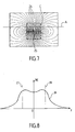
- Figure 7 shows the typical shape of the field lines magnetic 24 generated by a single conductive turn 25 traversed by a uniform electric current.
- Figure 7 corresponds more precisely in the case of a circular turn 25, so that this figure must be understood as having a symmetry of revolution around a vertical axis passing through the middle of the coil 25.
- the conductive loop formed by cable 11 or 12 is not exactly circular in the embodiment shown in figure 1, Figure 7 provides a first approximation of the distribution of magnetic field generated by such a conductive loop.
- such conductive loop generates a magnetic field whose intensity is maximum inside a generally cylindrical zone C, delimited in broken lines in Figure 7, whose axis is perpendicular to the plane containing the loop and whose generating curve corresponds substantially around the loop.
- the field magnetic is oriented substantially perpendicular to the plane containing the loop.
- the loop conductive surrounds a detection zone when said detection zone detection is essentially included in zone C corresponding to said conductive loop.
- zone C corresponding to said loop extends mainly on the interior side of the vehicle with respect to said wall, because this makes a screen which attenuates the magnetic field on the side exterior of the vehicle.
- the field distribution obtained through the vehicle 1 is represented diagrammatically by the curve 26 in FIG. 8.
- the abscissa y represents the displacement in the transverse direction of the vehicle 1, the origin being in the middle of the vehicle .
- the amplitude is represented
- the lines in phantom 27 and 28 respectively represent the location of the side walls 7 and 8. It can be seen that the magnetic field has a maximum and substantially uniform amplitude in the space 4, between the side walls 7 and 8 and has a decrease stiff outside the side walls 7 and 8.
- the field distribution generated by the cable 12 is similar.
- the amplitude of the recess formed by the curve 26 in the middle of the vehicle increases with the width, respectively with the length of the loop 11. If the amplitude of this recess is too large and prevents satisfactory discrimination between the inside and outside of the loop 11 as a function of the amplitude
- the hands-free control system operates from the next way.
- the user wearing the identifier 3 performs an initialization action, for example it activates the handle a front door, which sends an awakening signal to the central unit 2, which reacts to this signal by emitting a first radiofrequency signal from the antenna 6, as indicated by the arrow 10 in FIG. 1, by example by amplitude modulation of a carrier wave at 125 kHz.
- the identifier 3 receives a signal of greater or lesser amplitude.
- identifier 3 When identifier 3 is inside living space 4, it receives a signal maximum amplitude, which is for example greater than 5 mV at the level of the antenna receiving the identifier 3.
- the identifier 3 When the identifier 3 is at outside of the living space 4, it receives a more amplitude signal weak, which is for example less than 2 mV at 0.2 m distance from the vehicle 1.
- the identifier 3 is from the vehicle, the more the amplitude of the received signal is low.
- the identifier 3 is at a position where the execution of the requested command is authorized in detecting the amplitude of the signal received by identifier 3 and comparing this amplitude at a predetermined authorization threshold.
- this threshold is set between 2 and 5 mV at the antenna of identifier 3.
- the identifier 3 can be provided with a logic circuit allowing to measure the amplitude of the received field. When this measure indicates an amplitude above the authorization threshold, identifier 3 decides to continue the control process by sending a signal response to the central processing unit 2, according to the known technique.
- the identifier 3 decides to prohibit the execution of the commands and sends no response signal to central unit 2, this which ends the execution of the command until a new one wake-up signal is produced by a user initialization action.
- the identifier 3 responds to the unit control unit 2 using a signal containing the measured amplitude value by the identifier 3.
- the central unit 2 which decides to whether or not to continue executing the command based on this amplitude value.
- the measurement of the amplitude of the field received explicitly indicates the location of identifier 3.
- the identifier 3 is not provided with means for amplitude measurement of the received field but simply presents a threshold of fixed reception, set analogically, for example between 2 and 5 mV. In this case, when the amplitude of the field at the antenna of the identifier 3 is less than this reception threshold, the identifier 3 does not not receive the first signal 10 and the process is actually terminated. Conversely, when the amplitude of the field at the antenna level identifier 3 is greater than or equal to this threshold, identifier 3 receives the first signal 10 and responds to the central unit with a signal authentication in order to continue executing the command, according to the known technique. We then obtain an implicit indication of the location of the identifier 3.
- the central unit 2 is designed to preferably so as to be able to emit the first signal 10 to several times in response to the initialization action, with a level of power which increases with each iteration until the identifier 3 receives the first signal 10 or a maximum power level is achieved.
- the central unit 2 begins by transmitting for the first time the first signal 10, with a minimum power level. This level minimum is set, depending on the reception threshold of identifier 3, of so that identifier 3 cannot receive this first occurrence of the first signal 10 that being in a detection zone of small size, for example less than 20 cm outside the vehicle.
- Either the identifier 3 receives the first signal 10 and responds to central unit 2 with an authentication signal in order to continue execution of the order; either he does not receive it.
- the unit control unit 2 After a lapse of sufficient time to allow identifier 3 to respond, the unit control unit 2, when it has not received the authentication signal, transmits to again the first signal 10, with an increased power level, of so that the identifier 3 can receive this second occurrence of the first signal when in a larger detection area larger than the first time, for example within 50 cm of the vehicle.
- the process can be repeated several times, for example with three or more separate transmit power levels.
- the central unit can determine in which zone the identifier is located and decide to whether or not to continue executing the command.
- the maximum transmit power is determined to cover exactly one detection zone corresponding to the safety limit beyond which no order execution is authorized.
- the above-mentioned transmission method is not limited neither to a particular type of antenna, nor to a type of receiver particular. It is applicable to any signal transmission device on board a vehicle, regardless of the antenna design resignation.
- the configuration of cables 11 and 12 forming the antenna 6 thus allows, at a very low cost of equipment and installation, take into account the position of identifier 3 in relation to vehicle 1, in particular with respect to living space 4 and by in relation to the space in the safe 5, when the execution of an order is requested, in order to authorize or prohibit this execution.
- the position of the identifier 3 in relation to the living space 4 and the position of the identifier 3 relative to the space of the trunk 5 can be successively evaluated by successively supplying the cable 11 and the cable 12 in the context of the method described above.
- the location of the identifier 3 by relative to the detection zones surrounded by the antenna 6 can be obtained, explicitly or implicitly, with spatial resolution about 0.5 m.
- the cable 11 has a modified contour to avoid surround the location of the driver's seat 14, as shown by the contour 15 in broken lines.
- a third cable, no shown, is then arranged only around the seat 14 in order to hold account of the position of the identifier 3 with respect to this area so specific, for example to authorize an order for start-up.
- the antenna 106 is made differently from the antenna 6 of FIG. 1.
- the antenna 106 comprises a conductive cable 111 which extends along the upper surface or bottom of the floor wall 109 of the vehicle 101, along a line longitudinal median of the vehicle 101, and the wall 109 itself.
- the cable 111 has a terminal 111a located at the level of the wall of separation between the living space 104 and the trunk 105, and a terminal 111b located at the front apron separating the space 104 from the engine.
- Terminal 111b is electrically connected to the floor wall 109 of the vehicle, which is made of conductive metal, typically steel.
- the floor wall 109 carries a second terminal 109a in the vicinity of the terminal 111a of the cable 111.
- the floor wall 109 and the cable 111 thus form a conductive loop which is powered by the unit control unit 102 to emit a magnetic field, similar to antenna 6 of FIG. 1.
- the antenna 106 can be supplied with power by connecting terminal 111a and terminal 109a to the terminals of the circuit of the figure 3 or 9 or 10.
- the intensity induced in the secondary winding 22 flows in one direction through the cable 111, for example forward in the example shown in FIG. 2, and flows in the opposite direction through the floor wall 109, with a substantially uniform distribution, as indicated by arrows 131.
- connection the terminal 111b at the front apron above the wall 109 for example behind the dashboard of vehicle 101.
- Another possibility is to interpose a crowded electrical connector 129 between the terminal 111b and the wall 109.
- a similar connector 130 can also be interposed between the wall 109 and the terminal 109a.
- Leg connectors goose 129 and 130 can be made in good metal plates conductive, like copper, or be formed by bundles of wires in good conductive metal, for example with three or more wires.
- the magnetic field distribution obtained using the transmitting antenna 106 has advantages similar to those of the first embodiment.
- This embodiment is characterized by the realization of a conductive loop partially made up of conductive cable and partially from one or more conductive walls of the vehicle.
- cable 111 extending in the middle of the vehicle
- two can be provided cables parallel to it and extending over the floor wall 109 of so as to follow the passenger compartment on its two edges.
- a cable can also be arranged laterally, like the cable 112 in FIG. 2.
- the cable 112 has a connection terminal 112a located in the trunk 105 at proximity of a connection terminal 109b of the floor wall 109, and a terminal 112b electrically connected to the floor wall 109 of the vehicle.
- the arrow 134 represents the return of the current in the wall of floor when the connection terminals 109b and 112a are supplied.
- the antenna 206 is made differently from the antenna 6 of FIG. 1.
- the antenna 206 is formed directly by the metallic structure of the vehicle 201, as visible in FIG. 4.
- the central unit not shown, supplies power antenna 206 by means of a circuit similar to the circuit of FIG. 3, except for the transformer.
- the transformer 20 was produced in the form of a printed circuit
- the transformer 220 visible in Figure 6, is made against the carcass of the vehicle 201.
- the transformer 220 has a magnetic core 223 which is a rectangular section ferrite bar fixed against a side pillar 233 of vehicle 201, i.e. against the interior surface of the wall side 208 between the front door and the rear door.
- the transformer 220 is formed by the core 233 and by the pillar 233 in this embodiment.
- Winding 219 surrounds a central part of the magnetic core 223.
- the carcass of the vehicle 201 including side pillar 233, roof wall 232, wall pillar opposite side 207, and the floor wall 209, forms a ring conductor which completely surrounds the magnetic core 223. From this done, the vehicle structure fulfills itself the function transformer secondary winding 220.
- the winding 219 can be supplied by the circuit of the FIG. 3, in which case it replaces the winding 19 of FIG. 3, or again by the circuit of figure 9 or 10.
- the magnetic field distribution obtained using the transmitting antenna 206 has advantages similar to those of the first embodiment.
- the cost of producing antenna 206 is weak since the antenna is in fact made up of structural elements pre-existing vehicle which is given a second function.
- the antenna 206 could be made to other locations on vehicle 201, for example around the windshield or around the rear window, the only constraint being to have conductive elements arranged in a ring at the walls of the vehicle 201. Such a ring could also extend in the longitudinal direction of the vehicle, substantially in a vertical plane, to generate a magnetic field generally transverse to vehicle, as in the second embodiment.
Landscapes
- Engineering & Computer Science (AREA)
- Mechanical Engineering (AREA)
- Remote Sensing (AREA)
- Radar, Positioning & Navigation (AREA)
- General Physics & Mathematics (AREA)
- Computer Security & Cryptography (AREA)
- Physics & Mathematics (AREA)
- Computer Networks & Wireless Communication (AREA)
- Lock And Its Accessories (AREA)
- Devices For Checking Fares Or Tickets At Control Points (AREA)
- Near-Field Transmission Systems (AREA)
- Selective Calling Equipment (AREA)
- Arrangements For Transmission Of Measured Signals (AREA)
Abstract
Description
- la figure 1 est une vue de dessus écorchée d'un véhicule selon un premier mode de réalisation n'appartenant pas à l'invention, mais utile à sa compréhension,
- la figure 2 est une vue de dessus écorchée d'un véhicule selon un deuxième mode de réalisation conforme à l'invention,
- la figure 3 est une représentation schématique d'un circuit d'alimentation de l'antenne d'émission des véhicules selon l'invention,
- la figure 4 est une vue en coupe selon la ligne IV-IV de la figure 5 d'un véhicule selon un troisième mode de réalisation conforme à l'invention,
- la figure 5 est une vue latérale du véhicule de la figure 4,
- la figure 6 est une vue partielle du véhicule de la figure 4 en coupe selon la ligne VI-VI,
- la figure 7 représente les lignes du champ magnétique engendré par une spire simple parcourue par un courant électrique,
- la figure 8 représente de manière schématique la distribution de champ magnétique obtenue à l'aide de l'antenne du véhicule selon les différents modes de réalisation de l'invention,
- la figure 9 est une représentation schématique d'un autre circuit d'alimentation de l'antenne d'émission des véhicules selon l'invention,
- la figure 10 est une représentation schématique d'encore un autre circuit d'alimentation de l'antenne d'émission des véhicules selon l'invention.
Claims (11)
- Véhicule (101 ; 201) comportant un espace intérieur (104 ; 204) délimité par des parois (107, 108, 109 ; 207, 208, 209, 232) et un dispositif de transmission de signaux embarqué (102) destiné à communiquer avec un dispositif récepteur portatif (3) pour mettre en oeuvre un procédé de commande à distance, ledit dispositif de transmission de signaux étant muni d'une antenne d'émission (106 ; 206), ladite antenne d'émission comprenant au moins une boucle conductrice fermée (106 ; 206) pour engendrer un champ magnétique (B), ladite boucle conductrice étant configurée de manière à longer au moins une desdites parois le long d'une zone de détection dans laquelle la présence du dispositif récepteur portatif doit être détectée, caractérisé par le fait que ladite boucle conductrice comprend au moins une paroi conductrice (109 ; 207, 208, 209, 232) dudit véhicule.
- Véhicule selon la revendication 1, caractérisé par le fait que ladite au moins une paroi conductrice comprend au moins l'une parmi une paroi de plancher (109 ; 209), une paroi de toit (232) et une paroi latérale de carrosserie (207, 208) dudit véhicule.
- Véhicule selon l'une des revendications 1 à 2, caractérisé par le fait que ladite boucle conductrice comprend au moins un câble conducteur (111) longeant au moins une desdites parois.
- Véhicule selon la revendication 3, caractérisé par le fait que ledit ou chaque câble conducteur (111) est raccordé à ladite paroi conductrice (109) par un connecteur électrique en patte d'oie (129) de manière à diffuser le courant électrique parcourant ledit câble conducteur dans ladite paroi conductrice.
- Véhicule selon la revendication 3 ou 4, caractérisé par le fait que ledit ou chaque câble conducteur (111, 112) s'étend selon une direction longitudinale ou latérale du véhicule (101) le long d'une des surfaces inférieure et supérieure de ladite paroi de plancher.
- Véhicule selon l'une des revendications 1 à 5, caractérisé par le fait que ladite boucle conductrice (206) est configurée de manière à entourer ladite zone de détection (204).
- Véhicule selon l'une des revendications 1 à 6, caractérisé par le fait que ladite boucle conductrice (206) est intégralement formée par des parois conductrices (207, 208, 209, 232) dudit véhicule (201) reliées en forme d'anneau.
- Véhicule selon la revendication 7, caractérisé par le fait que lesdites parois conductrices comprennent une paroi de plafond (232), une paroi de plancher (209), et deux piliers latéraux (233) reliant lesdites parois de plafond et de plancher.
- Véhicule selon la revendication 7 ou 8, caractérisé par le fait qu'il comporte plusieurs boucles conductrices entourant plusieurs zones distinctes dudit espace intérieur.
- Véhicule selon l'une des revendications 1 à 9, caractérisé par le fait que ladite antenne d'émission (106 ; 206) est alimentée par l'intermédiaire d'un transformateur (20 ; 220) comportant un circuit magnétique (23 ; 223, 233) à faible réluctance traversant respectivement un enroulement primaire (19, 219) et un enroulement secondaire (22 ; 206) alimentant ladite boucle conductrice.
- Véhicule selon la revendication 10 prise en combinaison avec la revendication 8, caractérisé par le fait que ledit enroulement secondaire (206) est formé par lesdites parois conductrices (207, 208, 209, 232) reliées en forme d'anneau, ledit circuit magnétique (223) étant disposé contre au moins une (208) desdites parois conductrices.
Applications Claiming Priority (2)
| Application Number | Priority Date | Filing Date | Title |
|---|---|---|---|
| FR0205897A FR2839785B1 (fr) | 2002-05-14 | 2002-05-14 | Vehicule muni d'un dispositif de transmission de signaux |
| FR0205897 | 2002-05-14 |
Publications (2)
| Publication Number | Publication Date |
|---|---|
| EP1363354A1 true EP1363354A1 (fr) | 2003-11-19 |
| EP1363354B1 EP1363354B1 (fr) | 2005-10-26 |
Family
ID=29266099
Family Applications (2)
| Application Number | Title | Priority Date | Filing Date |
|---|---|---|---|
| EP03291039A Expired - Lifetime EP1363354B1 (fr) | 2002-05-14 | 2003-04-29 | Véhicule muni d'un dispositif de transmission de signaux embarqué |
| EP03291038A Expired - Lifetime EP1363353B1 (fr) | 2002-05-14 | 2003-04-29 | Véhicule muni d'un dispositif de transmission de signaux |
Family Applications After (1)
| Application Number | Title | Priority Date | Filing Date |
|---|---|---|---|
| EP03291038A Expired - Lifetime EP1363353B1 (fr) | 2002-05-14 | 2003-04-29 | Véhicule muni d'un dispositif de transmission de signaux |
Country Status (4)
| Country | Link |
|---|---|
| EP (2) | EP1363354B1 (fr) |
| AT (2) | ATE364914T1 (fr) |
| DE (2) | DE60302004T2 (fr) |
| FR (1) | FR2839785B1 (fr) |
Cited By (1)
| Publication number | Priority date | Publication date | Assignee | Title |
|---|---|---|---|---|
| FR2910751A1 (fr) * | 2006-12-22 | 2008-06-27 | Valeo Securite Habitacle Sas | Procede de detection d'un objet d'identification dans un vehicule. |
Families Citing this family (4)
| Publication number | Priority date | Publication date | Assignee | Title |
|---|---|---|---|---|
| DE10355891A1 (de) * | 2003-11-29 | 2005-06-30 | Daimlerchrysler Ag | Verfahren zur Steuerung eines Antennensystems eines Zugangsberechtigungssystems für Kraftfahrzeuge |
| EP1601048A1 (fr) * | 2004-05-28 | 2005-11-30 | Delphi Technologies, Inc. | Dispositif de communication avec une antenne inductive |
| DE102004035562B4 (de) * | 2004-07-22 | 2023-04-13 | HELLA GmbH & Co. KGaA | Antennenanordnung in einem Kraftfahrzeug, zum Beispiel für ein Diebstahlschutzsystem |
| DE102019105600A1 (de) * | 2019-03-06 | 2020-09-10 | Dr. Ing. H.C. F. Porsche Aktiengesellschaft | Kraftfahrzeug |
Citations (5)
| Publication number | Priority date | Publication date | Assignee | Title |
|---|---|---|---|---|
| US4873530A (en) * | 1985-09-30 | 1989-10-10 | Nissan Motor Co., Ltd. | Antenna device in automotive keyless entry system |
| WO1997016331A1 (fr) * | 1995-10-31 | 1997-05-09 | Geosoft-Eastlink (Geolink) | Systeme antivol pour vehicule |
| EP0992408A2 (fr) | 1998-10-10 | 2000-04-12 | DaimlerChrysler AG | Procédé permettant de réaliser l'autorisation d'accès pour un véhicule à moteur |
| FR2786030A1 (fr) * | 1998-11-16 | 2000-05-19 | Valeo Securite Habitacle | Vehicule automobile equipe d'un dispositif identifieur assurant la commande d'organes de manoeuvre du vehicule lorsqu'un identifiant est detecte dans un espace predetermine |
| FR2808125A1 (fr) * | 2000-04-20 | 2001-10-26 | Valeo Electronique | Vehicule automobile equipe d'une antenne exploitee pour un systeme d'acces mains libres |
Family Cites Families (5)
| Publication number | Priority date | Publication date | Assignee | Title |
|---|---|---|---|---|
| US3560983A (en) * | 1967-09-12 | 1971-02-02 | Volkers Research Corp | Omnidirectional loop antenna |
| FR2753570B1 (fr) * | 1996-09-18 | 1998-11-27 | Siemens Automotive Sa | Antenne inductive |
| US6489883B1 (en) * | 1997-04-30 | 2002-12-03 | Matsushita Electric Industrial Co., Ltd. | Non-contact data carrier system |
| FR2810946B3 (fr) * | 2000-07-03 | 2002-04-19 | Valeo Electronique | Vehicule automobile equipe d'un systeme d'acces dit "mains libres" perfectionne pour localiser un badge portatif |
| JP3899505B2 (ja) * | 2000-08-30 | 2007-03-28 | オムロン株式会社 | 無線装置 |
-
2002
- 2002-05-14 FR FR0205897A patent/FR2839785B1/fr not_active Expired - Fee Related
-
2003
- 2003-04-29 EP EP03291039A patent/EP1363354B1/fr not_active Expired - Lifetime
- 2003-04-29 AT AT03291038T patent/ATE364914T1/de not_active IP Right Cessation
- 2003-04-29 AT AT03291039T patent/ATE308126T1/de not_active IP Right Cessation
- 2003-04-29 DE DE60302004T patent/DE60302004T2/de not_active Expired - Lifetime
- 2003-04-29 EP EP03291038A patent/EP1363353B1/fr not_active Expired - Lifetime
- 2003-04-29 DE DE60314332T patent/DE60314332T2/de not_active Expired - Lifetime
Patent Citations (5)
| Publication number | Priority date | Publication date | Assignee | Title |
|---|---|---|---|---|
| US4873530A (en) * | 1985-09-30 | 1989-10-10 | Nissan Motor Co., Ltd. | Antenna device in automotive keyless entry system |
| WO1997016331A1 (fr) * | 1995-10-31 | 1997-05-09 | Geosoft-Eastlink (Geolink) | Systeme antivol pour vehicule |
| EP0992408A2 (fr) | 1998-10-10 | 2000-04-12 | DaimlerChrysler AG | Procédé permettant de réaliser l'autorisation d'accès pour un véhicule à moteur |
| FR2786030A1 (fr) * | 1998-11-16 | 2000-05-19 | Valeo Securite Habitacle | Vehicule automobile equipe d'un dispositif identifieur assurant la commande d'organes de manoeuvre du vehicule lorsqu'un identifiant est detecte dans un espace predetermine |
| FR2808125A1 (fr) * | 2000-04-20 | 2001-10-26 | Valeo Electronique | Vehicule automobile equipe d'une antenne exploitee pour un systeme d'acces mains libres |
Cited By (3)
| Publication number | Priority date | Publication date | Assignee | Title |
|---|---|---|---|---|
| FR2910751A1 (fr) * | 2006-12-22 | 2008-06-27 | Valeo Securite Habitacle Sas | Procede de detection d'un objet d'identification dans un vehicule. |
| WO2008077929A1 (fr) * | 2006-12-22 | 2008-07-03 | Valeo Securite Habitacle | Procede de detection d'un objet d'identification dans un vehicule |
| US8773240B2 (en) | 2006-12-22 | 2014-07-08 | Valeo Securite Habitacle | Method for detecting an identification object in a vehicle |
Also Published As
| Publication number | Publication date |
|---|---|
| EP1363354B1 (fr) | 2005-10-26 |
| DE60314332D1 (de) | 2007-07-26 |
| DE60302004T2 (de) | 2006-07-20 |
| FR2839785B1 (fr) | 2007-01-05 |
| DE60302004D1 (de) | 2005-12-01 |
| DE60314332T2 (de) | 2008-02-21 |
| EP1363353A1 (fr) | 2003-11-19 |
| EP1363353B1 (fr) | 2007-06-13 |
| ATE364914T1 (de) | 2007-07-15 |
| FR2839785A1 (fr) | 2003-11-21 |
| ATE308126T1 (de) | 2005-11-15 |
Similar Documents
| Publication | Publication Date | Title |
|---|---|---|
| FR2781445A1 (fr) | Dispositif de controle d'acces pour vehicule automobile et procede de reglage de la sensibilite de ce dispositif | |
| FR2775642A1 (fr) | Procede d'initialisation d'un systeme antivol pour vehicule automobile | |
| FR2589930A1 (fr) | Systeme de verrouillage pour voiture, commande par un signal radio | |
| FR3071001A1 (fr) | Dispositif de tele-alimentation repeteur de communication sans contact pour une poignee de porte de vehicule automobile | |
| FR3030906A1 (fr) | Unite electronique d'emissions basse frequence a destination d'une unite electronique de roue mobile d'un vehicule et procede de transmission de signaux basse frequence associe | |
| EP1363354B1 (fr) | Véhicule muni d'un dispositif de transmission de signaux embarqué | |
| WO2002020923A1 (fr) | Procede et dispositif de verrouillage automatique d'un vehicule automobile | |
| WO2019238696A1 (fr) | Dispositif de communication en champ proche a haute frequence et de rechargement par induction d'un appareil electronique portable | |
| WO2012080328A1 (fr) | Module electronique de communication pour le verrouillage/deverrouillage d'un ouvrant de vehicule automobile, unite centrale de commande associee et systeme d'acces mains-libres | |
| EP2007609A1 (fr) | Systeme de verrouillage automatique pour vehicule automobile | |
| BE1006005A3 (fr) | Procede et dispositif d'identification d'objets, notamment des vehicules automobiles. | |
| FR2755925A1 (fr) | Equipement de vehicule automobile comprenant un dispositif antivol et un dispositif a telecommande | |
| FR2766016A1 (fr) | Dispositif d'antenne pour systeme antivol de vehicule automobile | |
| FR3143486A1 (fr) | Dispositif d’activation d’une fonction vehicule | |
| EP1601048A1 (fr) | Dispositif de communication avec une antenne inductive | |
| EP1740420B1 (fr) | Dispositif d"identification pour un vehicule automobile equipe d"un systeme d"acces et / ou demarrage dit mains libres | |
| FR2816346A1 (fr) | Procede et dispositif de verrouillage automatique d'un vehicule automobile | |
| EP1478049A1 (fr) | Dispositif de communication embarqué dans un véhicule et identifiant portatif destiné à communiquer avec celui-ci | |
| EP2923350B1 (fr) | Procede et dispositif de transmission de donnees entre un vehicule et un dispositif au sol | |
| WO2006106126A1 (fr) | Dispositif d'antenne radiofrequence a boucles orthogonales | |
| FR2962706A1 (fr) | Detection de badge a distance constante autour d'un vehicule | |
| WO2004079918A2 (fr) | Dispositif d’emission et/ou de reception et systeme de securisation integrant un tel dispositif | |
| WO2007080305A1 (fr) | Coupe-circuit de batterie d'accumulateur commande a distance | |
| EP2115885A1 (fr) | Dispositif d'emission-reception de signaux | |
| EP0596762A1 (fr) | Dispositif antivol de direction pour véhicule automobile, et clé pour un tel dispositif |
Legal Events
| Date | Code | Title | Description |
|---|---|---|---|
| PUAI | Public reference made under article 153(3) epc to a published international application that has entered the european phase |
Free format text: ORIGINAL CODE: 0009012 |
|
| AK | Designated contracting states |
Kind code of ref document: A1 Designated state(s): AT BE BG CH CY CZ DE DK EE ES FI FR GB GR HU IE IT LI LU MC NL PT RO SE SI SK TR |
|
| AX | Request for extension of the european patent |
Extension state: AL LT LV MK |
|
| 17P | Request for examination filed |
Effective date: 20040423 |
|
| AKX | Designation fees paid |
Designated state(s): AT BE BG CH CY CZ DE DK EE ES FI FR GB GR HU IE IT LI LU MC NL PT RO SE SI SK TR |
|
| GRAP | Despatch of communication of intention to grant a patent |
Free format text: ORIGINAL CODE: EPIDOSNIGR1 |
|
| GRAS | Grant fee paid |
Free format text: ORIGINAL CODE: EPIDOSNIGR3 |
|
| GRAA | (expected) grant |
Free format text: ORIGINAL CODE: 0009210 |
|
| AK | Designated contracting states |
Kind code of ref document: B1 Designated state(s): AT BE BG CH CY CZ DE DK EE ES FI FR GB GR HU IE IT LI LU MC NL PT RO SE SI SK TR |
|
| PG25 | Lapsed in a contracting state [announced via postgrant information from national office to epo] |
Ref country code: AT Free format text: LAPSE BECAUSE OF FAILURE TO SUBMIT A TRANSLATION OF THE DESCRIPTION OR TO PAY THE FEE WITHIN THE PRESCRIBED TIME-LIMIT Effective date: 20051026 Ref country code: SK Free format text: LAPSE BECAUSE OF FAILURE TO SUBMIT A TRANSLATION OF THE DESCRIPTION OR TO PAY THE FEE WITHIN THE PRESCRIBED TIME-LIMIT Effective date: 20051026 Ref country code: NL Free format text: LAPSE BECAUSE OF FAILURE TO SUBMIT A TRANSLATION OF THE DESCRIPTION OR TO PAY THE FEE WITHIN THE PRESCRIBED TIME-LIMIT Effective date: 20051026 Ref country code: RO Free format text: LAPSE BECAUSE OF FAILURE TO SUBMIT A TRANSLATION OF THE DESCRIPTION OR TO PAY THE FEE WITHIN THE PRESCRIBED TIME-LIMIT Effective date: 20051026 Ref country code: SI Free format text: LAPSE BECAUSE OF FAILURE TO SUBMIT A TRANSLATION OF THE DESCRIPTION OR TO PAY THE FEE WITHIN THE PRESCRIBED TIME-LIMIT Effective date: 20051026 Ref country code: GB Free format text: LAPSE BECAUSE OF FAILURE TO SUBMIT A TRANSLATION OF THE DESCRIPTION OR TO PAY THE FEE WITHIN THE PRESCRIBED TIME-LIMIT Effective date: 20051026 Ref country code: FI Free format text: LAPSE BECAUSE OF FAILURE TO SUBMIT A TRANSLATION OF THE DESCRIPTION OR TO PAY THE FEE WITHIN THE PRESCRIBED TIME-LIMIT Effective date: 20051026 Ref country code: IE Free format text: LAPSE BECAUSE OF FAILURE TO SUBMIT A TRANSLATION OF THE DESCRIPTION OR TO PAY THE FEE WITHIN THE PRESCRIBED TIME-LIMIT Effective date: 20051026 Ref country code: CZ Free format text: LAPSE BECAUSE OF FAILURE TO SUBMIT A TRANSLATION OF THE DESCRIPTION OR TO PAY THE FEE WITHIN THE PRESCRIBED TIME-LIMIT Effective date: 20051026 |
|
| REG | Reference to a national code |
Ref country code: GB Ref legal event code: FG4D Free format text: NOT ENGLISH |
|
| REG | Reference to a national code |
Ref country code: CH Ref legal event code: EP |
|
| REG | Reference to a national code |
Ref country code: IE Ref legal event code: FG4D Free format text: LANGUAGE OF EP DOCUMENT: FRENCH |
|
| REF | Corresponds to: |
Ref document number: 60302004 Country of ref document: DE Date of ref document: 20051201 Kind code of ref document: P |
|
| PG25 | Lapsed in a contracting state [announced via postgrant information from national office to epo] |
Ref country code: BG Free format text: LAPSE BECAUSE OF FAILURE TO SUBMIT A TRANSLATION OF THE DESCRIPTION OR TO PAY THE FEE WITHIN THE PRESCRIBED TIME-LIMIT Effective date: 20060126 Ref country code: SE Free format text: LAPSE BECAUSE OF FAILURE TO SUBMIT A TRANSLATION OF THE DESCRIPTION OR TO PAY THE FEE WITHIN THE PRESCRIBED TIME-LIMIT Effective date: 20060126 Ref country code: GR Free format text: LAPSE BECAUSE OF FAILURE TO SUBMIT A TRANSLATION OF THE DESCRIPTION OR TO PAY THE FEE WITHIN THE PRESCRIBED TIME-LIMIT Effective date: 20060126 Ref country code: DK Free format text: LAPSE BECAUSE OF FAILURE TO SUBMIT A TRANSLATION OF THE DESCRIPTION OR TO PAY THE FEE WITHIN THE PRESCRIBED TIME-LIMIT Effective date: 20060126 |
|
| PG25 | Lapsed in a contracting state [announced via postgrant information from national office to epo] |
Ref country code: ES Free format text: LAPSE BECAUSE OF FAILURE TO SUBMIT A TRANSLATION OF THE DESCRIPTION OR TO PAY THE FEE WITHIN THE PRESCRIBED TIME-LIMIT Effective date: 20060206 |
|
| PG25 | Lapsed in a contracting state [announced via postgrant information from national office to epo] |
Ref country code: PT Free format text: LAPSE BECAUSE OF FAILURE TO SUBMIT A TRANSLATION OF THE DESCRIPTION OR TO PAY THE FEE WITHIN THE PRESCRIBED TIME-LIMIT Effective date: 20060327 |
|
| NLV1 | Nl: lapsed or annulled due to failure to fulfill the requirements of art. 29p and 29m of the patents act | ||
| PG25 | Lapsed in a contracting state [announced via postgrant information from national office to epo] |
Ref country code: HU Free format text: LAPSE BECAUSE OF FAILURE TO SUBMIT A TRANSLATION OF THE DESCRIPTION OR TO PAY THE FEE WITHIN THE PRESCRIBED TIME-LIMIT Effective date: 20060427 |
|
| PG25 | Lapsed in a contracting state [announced via postgrant information from national office to epo] |
Ref country code: MC Free format text: LAPSE BECAUSE OF NON-PAYMENT OF DUE FEES Effective date: 20060430 Ref country code: BE Free format text: LAPSE BECAUSE OF NON-PAYMENT OF DUE FEES Effective date: 20060430 |
|
| REG | Reference to a national code |
Ref country code: IE Ref legal event code: FD4D |
|
| GBV | Gb: ep patent (uk) treated as always having been void in accordance with gb section 77(7)/1977 [no translation filed] |
Effective date: 20051026 |
|
| PLBE | No opposition filed within time limit |
Free format text: ORIGINAL CODE: 0009261 |
|
| STAA | Information on the status of an ep patent application or granted ep patent |
Free format text: STATUS: NO OPPOSITION FILED WITHIN TIME LIMIT |
|
| 26N | No opposition filed |
Effective date: 20060727 |
|
| REG | Reference to a national code |
Ref country code: CH Ref legal event code: PL |
|
| BERE | Be: lapsed |
Owner name: DELPHI TECHNOLOGIES, INC. Effective date: 20060430 |
|
| PG25 | Lapsed in a contracting state [announced via postgrant information from national office to epo] |
Ref country code: CH Free format text: LAPSE BECAUSE OF NON-PAYMENT OF DUE FEES Effective date: 20070430 Ref country code: LI Free format text: LAPSE BECAUSE OF NON-PAYMENT OF DUE FEES Effective date: 20070430 |
|
| PG25 | Lapsed in a contracting state [announced via postgrant information from national office to epo] |
Ref country code: EE Free format text: LAPSE BECAUSE OF FAILURE TO SUBMIT A TRANSLATION OF THE DESCRIPTION OR TO PAY THE FEE WITHIN THE PRESCRIBED TIME-LIMIT Effective date: 20051026 |
|
| PG25 | Lapsed in a contracting state [announced via postgrant information from national office to epo] |
Ref country code: TR Free format text: LAPSE BECAUSE OF FAILURE TO SUBMIT A TRANSLATION OF THE DESCRIPTION OR TO PAY THE FEE WITHIN THE PRESCRIBED TIME-LIMIT Effective date: 20051026 Ref country code: LU Free format text: LAPSE BECAUSE OF NON-PAYMENT OF DUE FEES Effective date: 20060429 |
|
| PG25 | Lapsed in a contracting state [announced via postgrant information from national office to epo] |
Ref country code: CY Free format text: LAPSE BECAUSE OF FAILURE TO SUBMIT A TRANSLATION OF THE DESCRIPTION OR TO PAY THE FEE WITHIN THE PRESCRIBED TIME-LIMIT Effective date: 20051026 |
|
| REG | Reference to a national code |
Ref country code: FR Ref legal event code: PLFP Year of fee payment: 14 |
|
| REG | Reference to a national code |
Ref country code: FR Ref legal event code: PLFP Year of fee payment: 15 |
|
| REG | Reference to a national code |
Ref country code: FR Ref legal event code: PLFP Year of fee payment: 16 |
|
| REG | Reference to a national code |
Ref country code: DE Ref legal event code: R082 Ref document number: 60302004 Country of ref document: DE Ref country code: DE Ref legal event code: R081 Ref document number: 60302004 Country of ref document: DE Owner name: APTIV TECHNOLOGIES LIMITED, BB Free format text: FORMER OWNER: DELPHI TECHNOLOGIES, INC., TROY, MICH., US |
|
| PGFP | Annual fee paid to national office [announced via postgrant information from national office to epo] |
Ref country code: PL Payment date: 20190516 Year of fee payment: 8 |
|
| PGFP | Annual fee paid to national office [announced via postgrant information from national office to epo] |
Ref country code: FR Payment date: 20190425 Year of fee payment: 17 |
|
| PG25 | Lapsed in a contracting state [announced via postgrant information from national office to epo] |
Ref country code: FR Free format text: LAPSE BECAUSE OF NON-PAYMENT OF DUE FEES Effective date: 20200430 |
|
| PG25 | Lapsed in a contracting state [announced via postgrant information from national office to epo] |
Ref country code: IT Free format text: LAPSE BECAUSE OF NON-PAYMENT OF DUE FEES Effective date: 20200429 |
|
| PGFP | Annual fee paid to national office [announced via postgrant information from national office to epo] |
Ref country code: DE Payment date: 20220422 Year of fee payment: 20 |
|
| REG | Reference to a national code |
Ref country code: DE Ref legal event code: R071 Ref document number: 60302004 Country of ref document: DE |
|
| P01 | Opt-out of the competence of the unified patent court (upc) registered |
Effective date: 20230425 |