EP1363076B1 - Multihole patch for combustor liner of a gas turbine engine - Google Patents
Multihole patch for combustor liner of a gas turbine engine Download PDFInfo
- Publication number
- EP1363076B1 EP1363076B1 EP03252644A EP03252644A EP1363076B1 EP 1363076 B1 EP1363076 B1 EP 1363076B1 EP 03252644 A EP03252644 A EP 03252644A EP 03252644 A EP03252644 A EP 03252644A EP 1363076 B1 EP1363076 B1 EP 1363076B1
- Authority
- EP
- European Patent Office
- Prior art keywords
- cooling
- liner
- combustor
- cooling holes
- multihole
- Prior art date
- Legal status (The legal status is an assumption and is not a legal conclusion. Google has not performed a legal analysis and makes no representation as to the accuracy of the status listed.)
- Expired - Fee Related
Links
Images


Classifications
-
- F—MECHANICAL ENGINEERING; LIGHTING; HEATING; WEAPONS; BLASTING
- F23—COMBUSTION APPARATUS; COMBUSTION PROCESSES
- F23R—GENERATING COMBUSTION PRODUCTS OF HIGH PRESSURE OR HIGH VELOCITY, e.g. GAS-TURBINE COMBUSTION CHAMBERS
- F23R3/00—Continuous combustion chambers using liquid or gaseous fuel
- F23R3/02—Continuous combustion chambers using liquid or gaseous fuel characterised by the air-flow or gas-flow configuration
- F23R3/04—Air inlet arrangements
- F23R3/06—Arrangement of apertures along the flame tube
-
- F—MECHANICAL ENGINEERING; LIGHTING; HEATING; WEAPONS; BLASTING
- F23—COMBUSTION APPARATUS; COMBUSTION PROCESSES
- F23R—GENERATING COMBUSTION PRODUCTS OF HIGH PRESSURE OR HIGH VELOCITY, e.g. GAS-TURBINE COMBUSTION CHAMBERS
- F23R3/00—Continuous combustion chambers using liquid or gaseous fuel
- F23R3/42—Continuous combustion chambers using liquid or gaseous fuel characterised by the arrangement or form of the flame tubes or combustion chambers
- F23R3/50—Combustion chambers comprising an annular flame tube within an annular casing
-
- F—MECHANICAL ENGINEERING; LIGHTING; HEATING; WEAPONS; BLASTING
- F23—COMBUSTION APPARATUS; COMBUSTION PROCESSES
- F23R—GENERATING COMBUSTION PRODUCTS OF HIGH PRESSURE OR HIGH VELOCITY, e.g. GAS-TURBINE COMBUSTION CHAMBERS
- F23R2900/00—Special features of, or arrangements for continuous combustion chambers; Combustion processes therefor
- F23R2900/03042—Film cooled combustion chamber walls or domes
-
- Y—GENERAL TAGGING OF NEW TECHNOLOGICAL DEVELOPMENTS; GENERAL TAGGING OF CROSS-SECTIONAL TECHNOLOGIES SPANNING OVER SEVERAL SECTIONS OF THE IPC; TECHNICAL SUBJECTS COVERED BY FORMER USPC CROSS-REFERENCE ART COLLECTIONS [XRACs] AND DIGESTS
- Y02—TECHNOLOGIES OR APPLICATIONS FOR MITIGATION OR ADAPTATION AGAINST CLIMATE CHANGE
- Y02T—CLIMATE CHANGE MITIGATION TECHNOLOGIES RELATED TO TRANSPORTATION
- Y02T50/00—Aeronautics or air transport
- Y02T50/60—Efficient propulsion technologies, e.g. for aircraft
Definitions
- the present invention relates generally to film cooled combustor liners for use in a gas turbine engine and, in particular, to such combustor liners including a multihole patch of cooling holes formed in regions thereof which experience an undesirable thermal gradient.
- Combustor liners are generally used in the combustion section of a gas turbine engine located between the compressor and turbine sections of the engine, although such liners may also be used in the exhaust sections of aircraft engines that employ augmentors.
- Combustors generally include an exterior casing and an interior combustor where fuel is burned to produce a hot gas at an intensely high temperature (e.g., 3000°F resp. 1649 °C or even higher).
- an intensely high temperature e.g., 3000°F resp. 1649 °C or even higher.
- a heat shield or combustor liner is provided in the interior of the combustor.
- liner designs have been disclosed in the art having different types of cooling schemes.
- One example of liner design includes a plurality of cooling slots formed therein by a plurality of cooling nuggets or the like, where a film of cooling air is provided along the hot side of the liner.
- Another liner design has been developed, as disclosed in U.S. Patent 5,181,379 to Wakeman et al. , U.S. Patent 5,233,828 to Napoli , and U.S. Patent 5,465,572 to Nicoll et al. , where a plurality of cooling holes have been formed in an annular one-piece liner to provide film cooling along the hot side of the liner.
- a combination of multihole cooling and slot-type cooling has been described in U.S.
- Patent 5,483,794 to Nicoll et al. U.S. Patent 5,279,127 to Napoli
- U.S. Patent 5,465,572 to Nicoll et al . and U.S. Patent 4,833,881 to Vdoviak et al .
- each of the aforementioned patents is primarily concerned with various ways in which to provide the desired cooling film for the liner while oftentimes attempting to minimize the amount of cooling air required therefor.
- the designs incorporating both multihole cooling and slot cooling involve a distinct separation (i.e., where the slot cooling is utilized in only a first or upstream portion of the liner and the multihole cooling is utilized in only a second or downstream portion of the liner as in the '881 patent), a single cooling slot being provided at an upstream end of the liner in order to assist in starting the cooling film of an otherwise multihole cooled liner as in the '127 patent, or a plurality of spaced cooling slots being provided upstream of separate multihole patterns extending circumferentially around the liner as in the '572 and '794 patents. None of these patents, however, disclose the use of discrete patches of multiholes being provided to augment the cooling film provided by cooling slots on nuggeted liners.
- U.S. Patent 6,205,789 to Patterson et al discloses a multihole film cooled combustor liner which includes a first group of cooling holes generally disposed therein and a second group of more densely spaced cooling holes incorporated with the first cooling hole group.
- This second group of cooling holes is provided at various locations of the liner where the cooling film is degraded, such as those regions subjected to swirl impingement or located immediately downstream of a large opening.
- the second cooling hole group is defined within certain regions, it must be compatible with the first cooling hole group by maintaining consistent axial spacing and hole size. This limits the flexibility of the pattern to address the specific thermal gradients experienced by the liner.
- an exemplary double annular combustor includes what is known as a co-rotating, no venturi (CONOVEN) swirler in the main dome. While this combustor is able to minimize emissions, it has been found that an extraordinary amount of hot gases impinge on the inner liner thereof. Such hot gas impingement has been found to produce early oxidation of the forward liner panels, which results in reduced life and combustor burn through in severe cases. In order to solve this problem, additional air is required to cool the distressed panel. Additional cooling flow has been gained in machined slot liners by increasing the size and/or number of the cooling holes feeding the cooling slot. This method has been effective in those cases where there is sufficient space to drill the required number/size of the holes for decreasing the panel temperature to an acceptable level, but the required space is not available in every instance.
- CONOVEN co-rotating, no venturi
- a combustor liner to be developed for use with a gas turbine engine combustor which provides additional cooling in discrete regions of the liner as required by the thermal gradients experienced. It would also be desirable for such multihole cooling patches to be utilized with liners having either slot cooling or multihole cooling.
- a liner for a combustor of a gas turbine engine comprising:
- FIG. 1 depicts an exemplary gas turbine engine 10 having in serial flow communication a fan 12, a high pressure compressor 14, and a combustor 16.
- Combustor 16 conventionally generates combustion gases that are discharged therefrom through a high pressure turbine nozzle assembly 18, from which the combustion gases are channeled to a conventional high pressure turbine 20 and, in turn, to a conventional low pressure turbine 22.
- High pressure turbine 20 drives high pressure compressor 14 through a suitable shaft 24, while low pressure turbine 22 drives fan 12 through another suitable shaft 26, all disposed coaxially about a longitudinal or axial centerline axis 28.
- combustor 16 further includes a combustion chamber 30 defined by an outer liner 32, an inner liner 34, and a dome 36 located at an upstream end thereof. It will be seen that a first fuel/air mixer 38 is located within an outer dome 40 and a second fuel/air mixer 42 is located within an inner dome 44 so as to introduce a mixture of fuel and air therein as desired. The mixture of fuel and air is then ignited by an igniter (not shown) and combustion gases are formed which are utilized to drive high pressure turbine 20 and low pressure turbine 22, respectively.
- igniter not shown
- inner liner 34 of the present invention is equally applicable to any type of combustor, including single annular combustors, which utilizes slot cooling.
- inner liner 34 is preferably annular in shape. More specifically, inner liner 34 includes a first end 46 located adjacent to an upstream end of combustor 16, where first end 46 is connected to a cowl 48 and dome 36 via a mechanical connection such as bolt 52 and nut 54, a welded connection, or other similar form of attachment.
- a heat shield 50 may also be connected to cowl 48, dome 36 and inner liner 34. It will be seen that heat shield 50 extends downstream and radially to the inside of an upstream portion of inner liner 34.
- a plurality of cooling slots 56 are preferably provided in inner liner 34, such as by individual nuggets 57, to promote a cooling film along a hot side 58 of inner liner 34.
- Inner liner 34 also includes a second end 60 located adjacent to a downstream end of combustor 16, where second end 60 is preferably connected to a seal assembly 62. In this way, inner liner 34 is able to move axially in accordance with any thermal growth and/or pressure fluctuations experienced.
- panel 0 (identified by reference numeral 64) is located upstream of a first or upstream nugget 65 and a cooling slot 66 provided therein
- panel 1 (identified by reference numeral 68) is located between first nugget 65 and a second nugget 67 (having a cooling slot 70 formed therein) located adjacent thereto, and so forth.
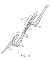
- Thermal barrier coatings 69 and 71 are applied to panels 64 and 68 to assist in overcoming impingement of hot gases, but it has been found that certain discrete regions or areas 72 on inner liner 34 are still subject to distress from oxidation and result in reduced life or potential burn through. Accordingly, the present invention includes a group of cooling holes, otherwise known herein as a multihole patch and identified collectively by reference numeral 74, formed in inner liner 34 at discrete region 72 to augment the cooling film and provide convective bore cooling to discrete region 72. It is preferred that cooling hole group 74 be formed in a pattern (as defined by a dotted boundary 75) approximating a thermal gradient pattern experienced by inner liner 34. As seen in Fig. 3 , pattern 75 is substantially a trapezoid, where cooling hole group 74 includes a plurality of rows 76 from an upstream row 78 to a downstream row 80.
- each cooling hole of group 74 preferably has a size in a range of approximately 0.38-0.89 mm (015-.035 of an inch). Further, it is preferred that the size of cooling holes 84 in downstream row 80 be larger than cooling holes 82 in the other rows. It is even more preferred that the size of cooling holes 82 get progressively larger from upstream row 78 to downstream row 80. Likewise, cooling holes 82 and 84 preferably have the greatest size adjacent to a centerline 86 extending through cooling hole group 74 and progressively decreases in size as each row extends circumferentially therefrom.
- cooling holes 82 and 84 in multihole patch 74 it is preferred that the rows be staggered circumferentially as seen in Fig. 3 .
- such cooling holes are preferably spaced in both the axial and circumferential direction in an amount equal to about 4.0 hole diameters. Since the diameter of cooling holes 82 are approximately 0.38-0.63 mm (015-.025 of an inch) and cooling holes 84 are approximately 0.63-0.89 mm (.025-.035 of an inch), the range of spacing is approximately 3.0-4.0 diameters.
- cooling holes 82 and 84 are preferably oriented at an incidence angle of about 15-25° with respect to inner liner 34.
- a multihole patch 74 is preferably positioned at a location adjacent each such fuel/air mixer 42 having approximately the same amount of offset 87 as described above.
- a second discrete region 88 where a multihole patch 90 having a second configuration has been found to be desirable is in panel 64 upstream of first nugget 65.
- a row 92 of cooling holes 94 is preferably located in second discrete region 88, where a centerline 96 through row 92 is offset from both centerline 89 through each fuel/air mixer 42 and centerline 86 of multihole patch 74 by predetermined amounts 98 and 100, respectively. It will be appreciated that while the size of cooling holes 94 may have approximately the same size throughout row 92, it would be preferable if the size thereof was greatest along centerline 96 and decreased as cooling holes 94 extended circumferentially therefrom. It will also be noted that second discrete region 88, and thus row 92 of cooling holes 94, preferably extends only partially between adjacent cups of combustor 16.
- inner liner 34 for combustor 16 can be accomplished by appropriate modifications by one of ordinary skill in the art without departing from the scope of the invention.
- the concepts described and claimed herein with respect to a slot cooled liner could be utilized in a liner having multihole cooling and still be compatible with the present invention.
- the multihole patch of the present invention could be applied with respect to other discrete regions of distress on inner liner 34, as well as to discrete regions of distress identified on outer liner 32.
Applications Claiming Priority (2)
| Application Number | Priority Date | Filing Date | Title |
|---|---|---|---|
| US10/134,283 US7086232B2 (en) | 2002-04-29 | 2002-04-29 | Multihole patch for combustor liner of a gas turbine engine |
| US134283 | 2002-04-29 |
Publications (3)
| Publication Number | Publication Date |
|---|---|
| EP1363076A2 EP1363076A2 (en) | 2003-11-19 |
| EP1363076A3 EP1363076A3 (en) | 2007-03-14 |
| EP1363076B1 true EP1363076B1 (en) | 2010-10-06 |
Family
ID=29249186
Family Applications (1)
| Application Number | Title | Priority Date | Filing Date |
|---|---|---|---|
| EP03252644A Expired - Fee Related EP1363076B1 (en) | 2002-04-29 | 2003-04-25 | Multihole patch for combustor liner of a gas turbine engine |
Country Status (5)
| Country | Link |
|---|---|
| US (1) | US7086232B2 (ja) |
| EP (1) | EP1363076B1 (ja) |
| JP (1) | JP4597489B2 (ja) |
| CN (1) | CN100529544C (ja) |
| DE (1) | DE60334421D1 (ja) |
Families Citing this family (36)
| Publication number | Priority date | Publication date | Assignee | Title |
|---|---|---|---|---|
| US7007481B2 (en) * | 2003-09-10 | 2006-03-07 | General Electric Company | Thick coated combustor liner |
| US6868675B1 (en) * | 2004-01-09 | 2005-03-22 | Honeywell International Inc. | Apparatus and method for controlling combustor liner carbon formation |
| US7000400B2 (en) * | 2004-03-17 | 2006-02-21 | Honeywell International, Inc. | Temperature variance reduction using variable penetration dilution jets |
| US7509809B2 (en) * | 2005-06-10 | 2009-03-31 | Pratt & Whitney Canada Corp. | Gas turbine engine combustor with improved cooling |
| US20070028595A1 (en) * | 2005-07-25 | 2007-02-08 | Mongia Hukam C | High pressure gas turbine engine having reduced emissions |
| US7631502B2 (en) * | 2005-12-14 | 2009-12-15 | United Technologies Corporation | Local cooling hole pattern |
| DE102006026969A1 (de) * | 2006-06-09 | 2007-12-13 | Rolls-Royce Deutschland Ltd & Co Kg | Gasturbinenbrennkammerwand für eine mager-brennende Gasturbinenbrennkammer |
| US7895841B2 (en) * | 2006-07-14 | 2011-03-01 | General Electric Company | Method and apparatus to facilitate reducing NOx emissions in turbine engines |
| US7669422B2 (en) * | 2006-07-26 | 2010-03-02 | General Electric Company | Combustor liner and method of fabricating same |
| US8312627B2 (en) * | 2006-12-22 | 2012-11-20 | General Electric Company | Methods for repairing combustor liners |
| US20080148565A1 (en) * | 2006-12-22 | 2008-06-26 | Edward John Emilianowicz | Methods for making combustor liner replacement panels |
| US20100031664A1 (en) * | 2006-12-22 | 2010-02-11 | Edward John Emilianowicz | Combustor liner replacement panels |
| FR2914986B1 (fr) * | 2007-04-12 | 2015-04-10 | Saint Gobain Isover | Bruleur a combustion interne |
| US8146364B2 (en) * | 2007-09-14 | 2012-04-03 | Siemens Energy, Inc. | Non-rectangular resonator devices providing enhanced liner cooling for combustion chamber |
| US8205457B2 (en) | 2007-12-27 | 2012-06-26 | General Electric Company | Gas turbine engine combustor and method for delivering purge gas into a combustion chamber of the combustor |
| US20110059321A1 (en) * | 2008-06-23 | 2011-03-10 | General Electric Company | Method of repairing a thermal barrier coating and repaired coating formed thereby |
| US8056343B2 (en) * | 2008-10-01 | 2011-11-15 | General Electric Company | Off center combustor liner |
| US20100107645A1 (en) * | 2008-10-31 | 2010-05-06 | General Electric Company | Combustor liner cooling flow disseminator and related method |
| US20100223931A1 (en) * | 2009-03-04 | 2010-09-09 | General Electric Company | Pattern cooled combustor liner |
| US8307657B2 (en) * | 2009-03-10 | 2012-11-13 | General Electric Company | Combustor liner cooling system |
| US8276253B2 (en) * | 2009-06-03 | 2012-10-02 | General Electric Company | Method and apparatus to remove or install combustion liners |
| US20110162378A1 (en) * | 2010-01-06 | 2011-07-07 | General Electric Company | Tunable transition piece aft frame |
| US8713776B2 (en) | 2010-04-07 | 2014-05-06 | General Electric Company | System and tool for installing combustion liners |
| US20130074471A1 (en) * | 2011-09-22 | 2013-03-28 | General Electric Company | Turbine combustor and method for temperature control and damping a portion of a combustor |
| US9243508B2 (en) * | 2012-03-20 | 2016-01-26 | General Electric Company | System and method for recirculating a hot gas flowing through a gas turbine |
| US20130318991A1 (en) * | 2012-05-31 | 2013-12-05 | General Electric Company | Combustor With Multiple Combustion Zones With Injector Placement for Component Durability |
| GB201315871D0 (en) | 2013-09-06 | 2013-10-23 | Rolls Royce Plc | A combustion chamber arrangement |
| WO2015039074A1 (en) * | 2013-09-16 | 2015-03-19 | United Technologies Corporation | Controlled variation of pressure drop through effusion cooling in a double walled combustor of a gas turbine engine |
| WO2015039075A1 (en) | 2013-09-16 | 2015-03-19 | United Technologies Corporation | Angled combustor liner cooling holes through transverse structure within a gas turbine engine combustor |
| EP4242520A3 (en) | 2013-10-24 | 2023-11-01 | RTX Corporation | Combustor for gas turbine engine with quench jet pattern |
| US10697636B2 (en) * | 2013-12-06 | 2020-06-30 | Raytheon Technologies Corporation | Cooling a combustor heat shield proximate a quench aperture |
| US20160153282A1 (en) * | 2014-07-11 | 2016-06-02 | United Technologies Corporation | Stress Reduction For Film Cooled Gas Turbine Engine Component |
| US10088167B2 (en) | 2015-06-15 | 2018-10-02 | General Electric Company | Combustion flow sleeve lifting tool |
| JP6026028B1 (ja) * | 2016-03-10 | 2016-11-16 | 三菱日立パワーシステムズ株式会社 | 燃焼器用パネル、燃焼器、燃焼装置、ガスタービン、及び燃焼器用パネルの冷却方法 |
| JP2018054210A (ja) * | 2016-09-28 | 2018-04-05 | 株式会社Ihi | 燃焼装置用ライナ |
| US11015529B2 (en) * | 2016-12-23 | 2021-05-25 | General Electric Company | Feature based cooling using in wall contoured cooling passage |
Family Cites Families (22)
| Publication number | Priority date | Publication date | Assignee | Title |
|---|---|---|---|---|
| US4733538A (en) * | 1978-10-02 | 1988-03-29 | General Electric Company | Combustion selective temperature dilution |
| US4833881A (en) | 1984-12-17 | 1989-05-30 | General Electric Company | Gas turbine engine augmentor |
| DE3803086C2 (de) * | 1987-02-06 | 1997-06-26 | Gen Electric | Brennkammer für ein Gasturbinentriebwerk |
| US4896510A (en) * | 1987-02-06 | 1990-01-30 | General Electric Company | Combustor liner cooling arrangement |
| FR2668246B1 (fr) * | 1990-10-17 | 1994-12-09 | Snecma | Chambre de combustion munie d'un dispositif de refroidissement de sa paroi. |
| US5181379A (en) | 1990-11-15 | 1993-01-26 | General Electric Company | Gas turbine engine multi-hole film cooled combustor liner and method of manufacture |
| US5233828A (en) | 1990-11-15 | 1993-08-10 | General Electric Company | Combustor liner with circumferentially angled film cooling holes |
| CA2056592A1 (en) | 1990-12-21 | 1992-06-22 | Phillip D. Napoli | Multi-hole film cooled combustor liner with slotted film starter |
| GB9127505D0 (en) | 1991-03-11 | 2013-12-25 | Gen Electric | Multi-hole film cooled afterburner combustor liner |
| US5241827A (en) * | 1991-05-03 | 1993-09-07 | General Electric Company | Multi-hole film cooled combuster linear with differential cooling |
| JPH06281144A (ja) * | 1993-03-29 | 1994-10-07 | Hitachi Eng Co Ltd | ガスタービン燃焼器 |
| US5363654A (en) | 1993-05-10 | 1994-11-15 | General Electric Company | Recuperative impingement cooling of jet engine components |
| US5460002A (en) | 1993-05-21 | 1995-10-24 | General Electric Company | Catalytically-and aerodynamically-assisted liner for gas turbine combustors |
| US6205789B1 (en) | 1998-11-13 | 2001-03-27 | General Electric Company | Multi-hole film cooled combuster liner |
| US6266961B1 (en) * | 1999-10-14 | 2001-07-31 | General Electric Company | Film cooled combustor liner and method of making the same |
| US6260359B1 (en) * | 1999-11-01 | 2001-07-17 | General Electric Company | Offset dilution combustor liner |
| GB2356924A (en) * | 1999-12-01 | 2001-06-06 | Abb Alstom Power Uk Ltd | Cooling wall structure for combustor |
| US6250082B1 (en) * | 1999-12-03 | 2001-06-26 | General Electric Company | Combustor rear facing step hot side contour method and apparatus |
| US6434821B1 (en) * | 1999-12-06 | 2002-08-20 | General Electric Company | Method of making a combustion chamber liner |
| US6543233B2 (en) * | 2001-02-09 | 2003-04-08 | General Electric Company | Slot cooled combustor liner |
| US6553767B2 (en) * | 2001-06-11 | 2003-04-29 | General Electric Company | Gas turbine combustor liner with asymmetric dilution holes machined from a single piece form |
| US6655146B2 (en) * | 2001-07-31 | 2003-12-02 | General Electric Company | Hybrid film cooled combustor liner |
-
2002
- 2002-04-29 US US10/134,283 patent/US7086232B2/en not_active Expired - Fee Related
-
2003
- 2003-04-25 DE DE60334421T patent/DE60334421D1/de not_active Expired - Lifetime
- 2003-04-25 EP EP03252644A patent/EP1363076B1/en not_active Expired - Fee Related
- 2003-04-28 JP JP2003123044A patent/JP4597489B2/ja not_active Expired - Fee Related
- 2003-04-29 CN CNB03128437XA patent/CN100529544C/zh not_active Expired - Fee Related
Also Published As
| Publication number | Publication date |
|---|---|
| US7086232B2 (en) | 2006-08-08 |
| US20030200752A1 (en) | 2003-10-30 |
| CN100529544C (zh) | 2009-08-19 |
| JP2004003835A (ja) | 2004-01-08 |
| DE60334421D1 (de) | 2010-11-18 |
| EP1363076A2 (en) | 2003-11-19 |
| JP4597489B2 (ja) | 2010-12-15 |
| EP1363076A3 (en) | 2007-03-14 |
| CN1455152A (zh) | 2003-11-12 |
Similar Documents
| Publication | Publication Date | Title |
|---|---|---|
| EP1363076B1 (en) | Multihole patch for combustor liner of a gas turbine engine | |
| JP5374031B2 (ja) | タービンエンジンにおけるNOxエミッションを低減するのを可能にするための装置及びガスタービンエンジン | |
| US5261223A (en) | Multi-hole film cooled combustor liner with rectangular film restarting holes | |
| EP0512670B1 (en) | Multi-hole film cooled combustor liner with preferential cooling | |
| JP4124585B2 (ja) | 選択的に傾斜させた冷却孔を有する燃焼器ライナ | |
| US6568187B1 (en) | Effusion cooled transition duct | |
| EP1096206B1 (en) | Low emissions combustor | |
| EP1001222B1 (en) | Multi-hole film cooled combustor liner | |
| US20080271457A1 (en) | Cooling Holes For Gas Turbine Combustor Having A Non-Uniform Diameter Therethrough | |
| US7506512B2 (en) | Advanced effusion cooling schemes for combustor domes | |
| EP0378505B1 (en) | Combustor fuel nozzle arrangement | |
| JP4677086B2 (ja) | フィルム冷却燃焼器ライナ及びその製造方法 | |
| US5682747A (en) | Gas turbine combustor heat shield of casted super alloy | |
| JPH04332316A (ja) | スロット付きフィルム創始手段を備えた多孔フィルム冷却燃焼器ライナ | |
| US6986253B2 (en) | Methods and apparatus for cooling gas turbine engine combustors | |
| US20100236248A1 (en) | Combustion Liner with Mixing Hole Stub | |
| JP3998494B2 (ja) | 交換可能なアフタバーナ熱シールド | |
| EP3130855B1 (en) | Combustor liner for a gas turbine with a hole arrangement | |
| GB2027868A (en) | Combustor dome assembly | |
| US7578134B2 (en) | Methods and apparatus for assembling gas turbine engines |
Legal Events
| Date | Code | Title | Description |
|---|---|---|---|
| PUAI | Public reference made under article 153(3) epc to a published international application that has entered the european phase |
Free format text: ORIGINAL CODE: 0009012 |
|
| AK | Designated contracting states |
Kind code of ref document: A2 Designated state(s): AT BE BG CH CY CZ DE DK EE ES FI FR GB GR HU IE IT LI LU MC NL PT RO SE SI SK TR |
|
| AX | Request for extension of the european patent |
Extension state: AL LT LV MK |
|
| PUAL | Search report despatched |
Free format text: ORIGINAL CODE: 0009013 |
|
| AK | Designated contracting states |
Kind code of ref document: A3 Designated state(s): AT BE BG CH CY CZ DE DK EE ES FI FR GB GR HU IE IT LI LU MC NL PT RO SE SI SK TR |
|
| AX | Request for extension of the european patent |
Extension state: AL LT LV MK |
|
| 17P | Request for examination filed |
Effective date: 20070914 |
|
| AKX | Designation fees paid |
Designated state(s): DE FR GB |
|
| 17Q | First examination report despatched |
Effective date: 20091111 |
|
| GRAP | Despatch of communication of intention to grant a patent |
Free format text: ORIGINAL CODE: EPIDOSNIGR1 |
|
| GRAS | Grant fee paid |
Free format text: ORIGINAL CODE: EPIDOSNIGR3 |
|
| GRAA | (expected) grant |
Free format text: ORIGINAL CODE: 0009210 |
|
| AK | Designated contracting states |
Kind code of ref document: B1 Designated state(s): DE FR GB |
|
| REG | Reference to a national code |
Ref country code: GB Ref legal event code: FG4D |
|
| REF | Corresponds to: |
Ref document number: 60334421 Country of ref document: DE Date of ref document: 20101118 Kind code of ref document: P |
|
| PLBE | No opposition filed within time limit |
Free format text: ORIGINAL CODE: 0009261 |
|
| STAA | Information on the status of an ep patent application or granted ep patent |
Free format text: STATUS: NO OPPOSITION FILED WITHIN TIME LIMIT |
|
| 26N | No opposition filed |
Effective date: 20110707 |
|
| REG | Reference to a national code |
Ref country code: DE Ref legal event code: R097 Ref document number: 60334421 Country of ref document: DE Effective date: 20110707 |
|
| REG | Reference to a national code |
Ref country code: FR Ref legal event code: PLFP Year of fee payment: 13 |
|
| PGFP | Annual fee paid to national office [announced via postgrant information from national office to epo] |
Ref country code: GB Payment date: 20150427 Year of fee payment: 13 Ref country code: DE Payment date: 20150429 Year of fee payment: 13 |
|
| PGFP | Annual fee paid to national office [announced via postgrant information from national office to epo] |
Ref country code: FR Payment date: 20150417 Year of fee payment: 13 |
|
| REG | Reference to a national code |
Ref country code: DE Ref legal event code: R119 Ref document number: 60334421 Country of ref document: DE |
|
| GBPC | Gb: european patent ceased through non-payment of renewal fee |
Effective date: 20160425 |
|
| REG | Reference to a national code |
Ref country code: FR Ref legal event code: ST Effective date: 20161230 |
|
| PG25 | Lapsed in a contracting state [announced via postgrant information from national office to epo] |
Ref country code: FR Free format text: LAPSE BECAUSE OF NON-PAYMENT OF DUE FEES Effective date: 20160502 Ref country code: GB Free format text: LAPSE BECAUSE OF NON-PAYMENT OF DUE FEES Effective date: 20160425 Ref country code: DE Free format text: LAPSE BECAUSE OF NON-PAYMENT OF DUE FEES Effective date: 20161101 |