EP1363051A2 - Brush seal - Google Patents
Brush seal Download PDFInfo
- Publication number
- EP1363051A2 EP1363051A2 EP03252455A EP03252455A EP1363051A2 EP 1363051 A2 EP1363051 A2 EP 1363051A2 EP 03252455 A EP03252455 A EP 03252455A EP 03252455 A EP03252455 A EP 03252455A EP 1363051 A2 EP1363051 A2 EP 1363051A2
- Authority
- EP
- European Patent Office
- Prior art keywords
- brush seal
- bristle
- features
- retainer
- side plate
- Prior art date
- Legal status (The legal status is an assumption and is not a legal conclusion. Google has not performed a legal analysis and makes no representation as to the accuracy of the status listed.)
- Granted
Links
- 238000000034 method Methods 0.000 claims abstract description 13
- 238000009434 installation Methods 0.000 claims abstract description 6
- 229910045601 alloy Inorganic materials 0.000 description 4
- 239000000956 alloy Substances 0.000 description 4
- 239000012530 fluid Substances 0.000 description 4
- 238000003466 welding Methods 0.000 description 3
- 229910000531 Co alloy Inorganic materials 0.000 description 2
- 229910001026 inconel Inorganic materials 0.000 description 2
- 238000007689 inspection Methods 0.000 description 2
- 238000004519 manufacturing process Methods 0.000 description 2
- 239000000463 material Substances 0.000 description 2
- 239000010935 stainless steel Substances 0.000 description 2
- 229910001220 stainless steel Inorganic materials 0.000 description 2
- 238000007792 addition Methods 0.000 description 1
- 238000012986 modification Methods 0.000 description 1
- 230000004048 modification Effects 0.000 description 1
- 238000007789 sealing Methods 0.000 description 1
Images



Classifications
-
- F—MECHANICAL ENGINEERING; LIGHTING; HEATING; WEAPONS; BLASTING
- F01—MACHINES OR ENGINES IN GENERAL; ENGINE PLANTS IN GENERAL; STEAM ENGINES
- F01D—NON-POSITIVE DISPLACEMENT MACHINES OR ENGINES, e.g. STEAM TURBINES
- F01D11/00—Preventing or minimising internal leakage of working-fluid, e.g. between stages
- F01D11/001—Preventing or minimising internal leakage of working-fluid, e.g. between stages for sealing space between stator blade and rotor
-
- F—MECHANICAL ENGINEERING; LIGHTING; HEATING; WEAPONS; BLASTING
- F01—MACHINES OR ENGINES IN GENERAL; ENGINE PLANTS IN GENERAL; STEAM ENGINES
- F01D—NON-POSITIVE DISPLACEMENT MACHINES OR ENGINES, e.g. STEAM TURBINES
- F01D11/00—Preventing or minimising internal leakage of working-fluid, e.g. between stages
- F01D11/005—Sealing means between non relatively rotating elements
-
- F—MECHANICAL ENGINEERING; LIGHTING; HEATING; WEAPONS; BLASTING
- F16—ENGINEERING ELEMENTS AND UNITS; GENERAL MEASURES FOR PRODUCING AND MAINTAINING EFFECTIVE FUNCTIONING OF MACHINES OR INSTALLATIONS; THERMAL INSULATION IN GENERAL
- F16J—PISTONS; CYLINDERS; SEALINGS
- F16J15/00—Sealings
- F16J15/16—Sealings between relatively-moving surfaces
- F16J15/32—Sealings between relatively-moving surfaces with elastic sealings, e.g. O-rings
- F16J15/3284—Sealings between relatively-moving surfaces with elastic sealings, e.g. O-rings characterised by their structure; Selection of materials
- F16J15/3288—Filamentary structures, e.g. brush seals
-
- F—MECHANICAL ENGINEERING; LIGHTING; HEATING; WEAPONS; BLASTING
- F05—INDEXING SCHEMES RELATING TO ENGINES OR PUMPS IN VARIOUS SUBCLASSES OF CLASSES F01-F04
- F05D—INDEXING SCHEME FOR ASPECTS RELATING TO NON-POSITIVE-DISPLACEMENT MACHINES OR ENGINES, GAS-TURBINES OR JET-PROPULSION PLANTS
- F05D2240/00—Components
- F05D2240/55—Seals
- F05D2240/56—Brush seals
Definitions
- the technician then places the removable retainer 67 against the brush seal 51. Finally, the technician secures the retainer 67 to the engine 50 using suitable fasteners 69 such as rivets. The support 65 and the retainer 67 sandwich the brush seal 51 in proper position within the engine 50.
- the present invention can either can either radially lengthen the retainer 109 similar to the support 109, or the present invention can use a replacement retainer 109 that made to-length.
- the proximal (i.e. radially outer) end of the retainer 109 abuts the bristles 113.
- the distal (i.e. radially inner) end of the retainer is laterally spaced from the bristles 113 to act as the windage cover.
Landscapes
- Engineering & Computer Science (AREA)
- General Engineering & Computer Science (AREA)
- Mechanical Engineering (AREA)
- Sealing Devices (AREA)
- Turbine Rotor Nozzle Sealing (AREA)
Abstract
Description
- This invention relates to a brush seals. Specifically, this invention relates to a brush seal for an apparatus that utilizes features of the apparatus as functioning elements of the brush seal. This enables the brush seal to have fewer parts.
- Brush seals prevent the escape of fluid (i.e. air) through a gap between two parts of an apparatus. One such apparatus that uses brush seals is a gas turbine engine. The placement of the brush seal in the engine typically prevents secondary flow from escaping through a gap between a stationary part (e.g. a diffuser case) and a rotating part (e.g. a turbine shaft). The brush seal can have other uses, such as sealing a gap between stationary parts of the engine.
- The brush seal mounts to a support and a removable retainer on the engine. Specifically, the brush seal mounts against the support and the removable retainer confines the brush seal against the support. The support typically engages a side plate of a conventional brush seal and the retainer typically engages a back plate of a conventional brush seal.
- Of the numerous parts involved in this arrangement of a conventional brush seal, some of the parts have redundancy with other parts. This redundancy could impact the weight, cost and complexity of the brush seal arrangement.
- It is an object of the present invention in a preferred embodiment at least to provide a brush seal with a reduced part count.
- It is a further object of the present invention in a preferred embodiment at least to reduce inventory costs.
- It is a further object of the present invention in a preferred embodiment at least to provide a lighter weight brush seal.
- It is a further object of the present invention in a preferred embodiment at least to provide a reduced cost brush seal.
- It is a further object of the present invention in a preferred embodiment at least to manufacture a brush seal assembly in fewer steps.
- It is a further object of the present invention in a preferred embodiment at least to assemble a brush seal with simpler fixturing.
- It is a further object of the present invention in a preferred embodiment at least to provide a brush seal assembly method that allows easier inspection.
- It is a further object of the present invention in a preferred embodiment at least to provide a brush seal assembly with reusable parts.
- It is a further object of the present invention in a preferred embodiment at least to reduce the cost of replacing a brush on an apparatus.
- From a first aspect, the present invention provides a brush seal for installation in an apparatus having features for securing said brush seal. The brush seal includes: a side plate; a back plate; and a bristle arrangement secured between the plate and back plate. The features of the apparatus act as the side plate and the back plate of the brush seal.
- From a second aspect, the present invention provides a method of installing a brush seal in an apparatus. The method comprises the steps of: providing an apparatus with features for securing the brush seal thereto; providing a bristle arrangement; and securing the bristle arrangement to the features. The features act as a back plate and a side plate for the bristle arrangement.
- From a third aspect, the present invention provides an apparatus having features for securing a brush seal thereto. The improvement comprises the features acting as a back plate and a side plate of the brush seal.
- Other uses and advantages of the present invention will become apparent to those skilled in the art upon reference to the specification and the drawings, in which:
- Figure 1 is a partial cross-sectional view of a conventional multiple stage brush seal installed in an apparatus;
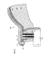
- Figure 2 is a partial cross-sectional view of one embodiment of a brush seal of the present invention installed in an apparatus;
- Figure 3 is a cross-sectional view of the brush seal of Figure 2 before installation in an apparatus;
- Figure 4 is a partial elevational view of one component of the brush seal of Figure 3;
- Figure 5 is a cross-sectional view of the component of Figure 4 taken along line V-V; and
- Figure 6 is a partial cross-sectional view of another embodiment of a brush seal of the present invention installed in an apparatus.
-
- Figure 1 provides a partial cross-sectional view of a
conventional apparatus 50 having abrush seal 51. Theapparatus 50 is preferably a gas turbine engine, but could be any other suitable machine. Thebrush seal 51 prevents secondary fluid flow from escaping through a gap between a first, typically stationary, part 53 (e.g. a diffuser case of a gas turbine engine) and a second, typically rotating, part 55 (e.g. a turbine shaft of a gas turbine engine). - The
brush seal 51 includes a side plate 57 (with an integral windage cover), a middle plate 59 and aback plate 61.Bristle packs 63 reside between theplates plates plates bristle packs 63 are welded together to form an assembly before placement in theengine 50. - The
brush seal 51 removably mounts to theengine 50. Theengine 50 includes asupport 65, such as an annular flange, and aremovable retainer 67 for mounting thebrush seal 51. As a first assembly step, the technician places thebrush seal 51 against thesupport 65 in theengine 50. - The technician then places the
removable retainer 67 against thebrush seal 51. Finally, the technician secures theretainer 67 to theengine 50 usingsuitable fasteners 69 such as rivets. Thesupport 65 and theretainer 67 sandwich thebrush seal 51 in proper position within theengine 50. - During operation, the
bristle packs 63 extend from thediffuser case 53 and engage theturbine shaft 55. In other words, the bristle packs 63 seal a gap between thediffuser case 53 and theturbine shaft 55 to prevent the escape of secondary fluid flow. - Figure 2 provides a partial cross-sectional view of an
apparatus 100 having abrush seal 101 of the present invention. As withapparatus 50, theapparatus 100 could be a gas turbine engine or other suitable machine. Thebrush seal 101 likewise prevents secondary fluid flow from escaping through a gap between a first part 103 (e.g. a diffuser case of a gas turbine engine) and a second part 105 (e.g. a turbine shaft of a gas turbine engine). - The
brush seal 101 removably mounts to theengine 100 using asupport 107, such as an annular flange, and aremovable retainer 109. As with theconventional brush seal 51, theretainer 109 secures to theengine 100 usingsuitable fasteners 111 such as rivets, snap rings (not shown), threaded fasteners (not shown) and retaining rings (not shown). Alternatively, theretainer 109 could be welded or brazed to theengine 100. When fastened to theengine 100, theretainer 109 sandwiches thebrush seal 101 against thesupport 107 for proper positioning of thebrush seal 101 within theengine 100. - Differently than the
conventional brush seal 51, thesupport 107 and theretainer 109 act as the side plate and the back plate of thebrush seal 101 of the present invention. The use of thesupport 107 and theretainer 109 as the side plate and the back plate has clear benefits. For example, thebrush seal 101 has fewer parts than theconventional brush seal 51. With fewer parts, thebrush seal 101 should reduce the weight of theengine 100, lower inventory costs, and have a lower manufacturing cost. Lacking the side plate and the back plate, the present invention can assemble thebrush seal 101 in fewer steps than with theconventional brush seal 51. For example, theconventional brush seal 51 requires the side plate and back plate to undergo a facing operation during assembly. The brush seal of the present invention does not. - Although Figure 2 shows an engine configuration with the
support 107 and theretainer 109 acting as the back plate and side plate, respectively, the engine could have a different configuration (not shown) with thesupport 107 and theretainer 109 acting as the side plate and back plate, respectively. - To act as the side plate and back plate of the brush, the
support 107 and theretainer 109 should have a different shape than thesupport 65 andretainer 67 of the conventional arrangement. Specifically, thesupport 107 and theretainer 109 should be radially lengthened and should approximate the shape of the side plate 57 (with the integral windage cover) and backplate 61 at locations adjacent thebrush seal 101. In an Original Equipment Manufacturer (OEM) situation, thesupport 107 and theretainer 109 could be manufactured to the new shape. In a post-OEM (e.g. repair) situation, thesupport 107 and theretainer 109 could have extra material added thereto such as by welding. - Likewise, the
brush seal 101 is different from theconventional brush seal 51. Figure 3 displaysbrush seal 101 before installation in theengine 100. The brush seal includes bristlearrangements 113 separated by amid plate 115. Notably, thebrush seal 101 lacks a side plate and a back plate. As discussed above, thesupport 107 and theretainer 109 of theengine 100 act as the side plate and back plate when the brush seal is installed in theengine 100. - Figures 4 and 5 show the
bristle arrangement 113 for the brush seal of the present invention. Although the figure only shows an arcuate segment, thebristle arrangement 113 is preferably annular. In an annular configuration, thebristle arrangement 113 can be referred to as a bristle ring. - The
bristle ring 113 includes a plurality ofbristles 117 made from a suitable alloy such as a cobalt alloy. An annular joint 119 secures the bristles together. Preferably, the joint 119 is a weld joint. European Patent Application number 03250864.0 describes in further detail the steps involved in making the bristlering 113. As seen in Figure 4, thebristles 117 are not aligned with a radial line of thebristle ring 113. Rather, thebristles 117 form a lay angle (in the direction of rotation of the turbine shaft 105) with the radial line of thebristle ring 113. - The
mid plate 115 for thebrush seal 101 of the present invention can be identical to themid plate 51 for theconventional brush seal 51. As with the plates of theconventional brush seal 51, themid plate 115 can be made from a suitable alloy, such as Inconel® or 400-series stainless steel. - The technician assembles the
brush seal 101 by first placing one bristlering 113 within a fixture (not shown). The technician then places themid plate 115 into the fixture, followed by thesecond bristle ring 113. The technician then secures another fixture (not shown) to the first fixture for holding the bristle rings 113 andmid plate 115 together temporarily. The fixturing used assemble thebristle ring 113 is simpler than the fixturing used to assemble theconventional brush seal 51. The conventional brush seal fixturing is more complex since the fixturing must accommodate the side plate and the back plate. The fixturing for the present invention does not require these complexities since thebrush seal 101 has neither a side plate nor a back plate. - The technician secures the bristle rings 113 and
mid plate 115 together using a suitable technique such as by welding. The technician can then disconnect the fixturing to reveal the fully assembledbrush seal 101 of the present invention. Lacking the side plate and the back plate, inspection of thebrush seal 101 of the present invention is easier than with conventional brush seals 51. Inspecting theconventional brush seal 51 is more difficult because the side plates and back plate can obscure portions of the weld joint. - Since the
brush seal 101 lacks a side plate and a back plate, the present invention modifies thesupport 107 and theretainer 109 to act as the side plate and the back plate. Specifically, thesupport 107 is radially lengthened. As with theback plate 61 of theconventional brush seal 51, the lengthenedsupport 107 engages a substantial length of thebristles 117 to limit bristle blowover in the flow direction. Thesupport 107 could be lengthened by, for example, welding additional material thereto. - Since the
retainer 109 is removable, the present invention can either can either radially lengthen theretainer 109 similar to thesupport 109, or the present invention can use areplacement retainer 109 that made to-length. As with theside plate 57 of the conventional brush seal, the proximal (i.e. radially outer) end of theretainer 109 abuts thebristles 113. The distal (i.e. radially inner) end of the retainer is laterally spaced from thebristles 113 to act as the windage cover. - Replacement of the
brush seal 101 of the present invention should be less expensive than the replacement of theconventional brush seal 51. When replacing theconventional brush seal 51, the technician removes therivets 69 to release theretainer 67, removes the brush seal 51 (including the side plate, back plate and bristle packs), provides a replacement brush seal (with side plate, back plate and bristle packs) and resecures theretainer 67. When replacing thebrush seal 101 of the present invention, the technician only needs to remove therivets 111 to release theretainer 109, remove thebristle ring 113, replace thebristle ring 113 and reattach theretainer 109. In essence (since the side plate and back plate are engine part not part of the brush seal 101), the present invention reuses the side plate and the back plate of the brush seal. - Although Figure 2 displays a multiple
stage brush seal 101, the present invention could also be used on a single stage brush seal. Figure 6 displays anengine 200 with such a singlestage brush seal 201. In the single stage version, thebrush seal 201 comprises just abristle ring 213. As with the multiple stage version, asupport 207 and aretainer 209 of theengine 200 act as the side plate and the back plate of thebrush seal 201. - The present invention has been described in connection with the preferred embodiments of the various figures. It is to be understood that other similar embodiments may be used or modifications and additions may be made to the described embodiment for performing the same function of the present invention without deviating therefrom. Therefore, the present invention should not be limited to any single embodiment, but rather construed in breadth and scope in accordance with the recitation of the appended claims.
Claims (17)
- A brush seal (101) for installation in an apparatus having features (107,109) for securing said brush seal, the brush seal comprising:wherein said features of said apparatus act as said side plate and said back plate.a side plate;a back plate; anda bristle arrangement (113) secured between said side plate and said back plate;
- The brush seal of claim 1, wherein said bristle arrangement comprises a bristle ring (113).
- The brush seal of claim 2, wherein said bristle ring (113) comprises a plurality of bristles (117) secured together by a joint (119).
- The brush seal of claim 3, wherein said joint (119) comprises a weld joint.
- The brush seal of any preceding claim, wherein said bristle arrangement comprises a plurality of bristle arrangements and further comprising a mid plate (115) located between adjacent bristle arrangements to form a multiple stage brush seal.
- The brush seal of claim 5, wherein said bristle arrangements are secured to said mid plates (115) before installation in said apparatus.
- The brush seal of any preceding claim, wherein said apparatus comprises a gas turbine engine.
- A method of installing a brush seal (101) in an apparatus (100), comprising the steps of:wherein said features act as a back plate and a side plate for said bristle arrangement.providing an apparatus with features (107,109) for securing said brush seal (101) thereto;providing a bristle arrangement (113); andsecuring said bristle arrangement to said features;
- The method of claim 8, wherein said bristle arrangement comprises a bristle ring (113).
- The method of claim 8 or 9, wherein said bristle arrangement providing step comprises providing a plurality of bristle arrangements (113) and a mid plate (115) between adjacent bristle arrangements.
- The method of claim 10, further comprising a step of securing said bristle arrangements (113) to said mid plates (115), wherein said bristle arrangements are secured to said mid plates before said bristle arrangements are secured between said features.
- The method of any of claims 8 to 11, wherein said features comprise a support (107) and a retainer (109).
- The method of claim 12, further comprising a step of lengthening said support (107) before said bristle arrangement securing step.
- The method of claim 12, further comprising either a step of lengthening said retainer (109) before said bristle arrangement securing step or a step of replacing said retainer with a lengthened retainer (109) before said bristle arrangement securing step.
- The method of any of claims 8 to 14, wherein said apparatus comprises a gas turbine engine.
- An apparatus having features (107,109) for securing a brush seal (101) thereto, wherein said features act as a back plate and a side plate of said brush seal.
- The apparatus of claim 16, wherein the apparatus comprises a gas turbine engine.
Applications Claiming Priority (2)
| Application Number | Priority Date | Filing Date | Title |
|---|---|---|---|
| US63463 | 2002-04-25 | ||
| US10/063,463 US20030201608A1 (en) | 2002-04-25 | 2002-04-25 | Brush seal with fewer parts |
Publications (3)
| Publication Number | Publication Date |
|---|---|
| EP1363051A2 true EP1363051A2 (en) | 2003-11-19 |
| EP1363051A3 EP1363051A3 (en) | 2004-03-03 |
| EP1363051B1 EP1363051B1 (en) | 2012-06-13 |
Family
ID=29248084
Family Applications (1)
| Application Number | Title | Priority Date | Filing Date |
|---|---|---|---|
| EP03252455A Expired - Lifetime EP1363051B1 (en) | 2002-04-25 | 2003-04-17 | Brush seal and method of installing a brush seal in an apparatus. |
Country Status (2)
| Country | Link |
|---|---|
| US (1) | US20030201608A1 (en) |
| EP (1) | EP1363051B1 (en) |
Cited By (1)
| Publication number | Priority date | Publication date | Assignee | Title |
|---|---|---|---|---|
| EP1522773A1 (en) * | 2003-10-08 | 2005-04-13 | United Technologies Corporation | Brush seal |
Families Citing this family (12)
| Publication number | Priority date | Publication date | Assignee | Title |
|---|---|---|---|---|
| US7000923B2 (en) * | 2004-01-09 | 2006-02-21 | United Technologies Corporation | Quick build brush seals |
| US7334311B2 (en) * | 2004-11-03 | 2008-02-26 | United Technologies Corporation | Method of forming a nested can brush seal |
| US7226054B2 (en) * | 2004-12-14 | 2007-06-05 | United Technologies Corporation | Clamp lock brush seal assembly |
| GB0619488D0 (en) * | 2006-10-03 | 2006-11-08 | Cross Mfg 1938 Company Ltd | Brush seal assembly |
| US20080136112A1 (en) * | 2006-12-08 | 2008-06-12 | United Technologies Corporation | Brush seal assemblies utilizing a threaded fastening method |
| US8505923B2 (en) * | 2009-08-31 | 2013-08-13 | Sealeze, A Unit of Jason, Inc. | Brush seal with stress and deflection accommodating membrane |
| US10132183B2 (en) * | 2013-03-07 | 2018-11-20 | United Technologies Corporation | Brush seal repair method |
| US9963991B2 (en) * | 2014-10-01 | 2018-05-08 | United Technologies Corporation | Brush seal plate |
| US20170292395A1 (en) * | 2016-04-07 | 2017-10-12 | United Technologies Corporation | Integrated brush seals |
| US11549588B2 (en) * | 2018-04-05 | 2023-01-10 | Raytheon Technologies Corporation | Brush seal with sliding backing plate |
| US11041397B1 (en) * | 2019-12-13 | 2021-06-22 | Raytheon Technologies Corporation | Non-metallic side plate seal assembly for a gas turbine engine |
| DE102021129985A1 (en) * | 2021-11-17 | 2023-05-17 | MTU Aero Engines AG | Brush seal with rub-tolerant back-up ring structure |
Citations (1)
| Publication number | Priority date | Publication date | Assignee | Title |
|---|---|---|---|---|
| EP0992721A1 (en) | 1998-10-08 | 2000-04-12 | ROLLS-ROYCE plc | Improved brush seal |
Family Cites Families (12)
| Publication number | Priority date | Publication date | Assignee | Title |
|---|---|---|---|---|
| US885032A (en) * | 1907-06-24 | 1908-04-21 | Sebastian Ziani De Ferranti | Fluid packing. |
| DE3514382C1 (en) * | 1985-04-20 | 1986-06-12 | Motoren Turbinen Union | Brush seal |
| GB8712681D0 (en) * | 1987-05-29 | 1987-07-01 | Cross Mfg Co 1938 Ltd | Brush seals |
| US5474306A (en) * | 1992-11-19 | 1995-12-12 | General Electric Co. | Woven seal and hybrid cloth-brush seals for turbine applications |
| US6173962B1 (en) * | 1995-12-09 | 2001-01-16 | Rolls Royce Plc | Brush seal |
| DE59710884D1 (en) * | 1996-10-02 | 2003-11-27 | Mtu Aero Engines Gmbh | brush seal |
| DE19641374C1 (en) * | 1996-10-08 | 1997-12-18 | Mtu Muenchen Gmbh | Device for production of brush seals |
| EP0905421B1 (en) * | 1997-09-25 | 2003-10-22 | ALSTOM (Switzerland) Ltd | Brush seal |
| US6257588B1 (en) * | 1998-09-22 | 2001-07-10 | General Electric Company | Brush seal and rotary machine including such brush seal |
| FR2787165B1 (en) * | 1998-12-10 | 2001-01-12 | Snecma | DOUBLE CONTACT BRUSH SEAL |
| US6378873B1 (en) * | 2000-06-02 | 2002-04-30 | General Electric Company | Low flow fluid film seal for hydrogen cooled generators |
| US6460857B1 (en) * | 2000-09-11 | 2002-10-08 | General Electric Company | Brush seal segment end bristle protection and flexibility maintenance device and methods of forming the segment |
-
2002
- 2002-04-25 US US10/063,463 patent/US20030201608A1/en not_active Abandoned
-
2003
- 2003-04-17 EP EP03252455A patent/EP1363051B1/en not_active Expired - Lifetime
Patent Citations (1)
| Publication number | Priority date | Publication date | Assignee | Title |
|---|---|---|---|---|
| EP0992721A1 (en) | 1998-10-08 | 2000-04-12 | ROLLS-ROYCE plc | Improved brush seal |
Cited By (1)
| Publication number | Priority date | Publication date | Assignee | Title |
|---|---|---|---|---|
| EP1522773A1 (en) * | 2003-10-08 | 2005-04-13 | United Technologies Corporation | Brush seal |
Also Published As
| Publication number | Publication date |
|---|---|
| EP1363051A3 (en) | 2004-03-03 |
| EP1363051B1 (en) | 2012-06-13 |
| US20030201608A1 (en) | 2003-10-30 |
Similar Documents
| Publication | Publication Date | Title |
|---|---|---|
| EP1363051B1 (en) | Brush seal and method of installing a brush seal in an apparatus. | |
| EP1347218B1 (en) | Brush seal | |
| EP1672256B1 (en) | Clamp lock and brush seal assembly | |
| US7584620B2 (en) | Support system for transition ducts | |
| EP2204539B1 (en) | Stator assembly for a gas turbine engine | |
| US20080029968A1 (en) | Nested can brush seal | |
| EP1375983A2 (en) | Replaceable brush seal elements | |
| EP1975514A2 (en) | A location ring arrangement | |
| CA2603595C (en) | Heat shield with stress relieving feature | |
| EP1424518A2 (en) | Brush seal with adjustable clearance | |
| EP1347217A2 (en) | Arrangements for brush seals | |
| JP5214280B2 (en) | Turbine nozzle segment and repair method thereof | |
| EP1335157B1 (en) | Bristle arrangement for brush seal, method and assembly for making same, and method of making brush seal | |
| EP1522773A1 (en) | Brush seal | |
| US10634349B2 (en) | Wear pad system for turbine combustion systems and method for coupling wear pad into turbine combustion system | |
| US20190017638A1 (en) | Balking tab to control duct coupling clocking | |
| EP2090753A2 (en) | Sealing assembly for a turbine engine and corresponding operating method | |
| US20240229657A9 (en) | Turbojet engine nozzle ring for an aircraft | |
| EP3379038B1 (en) | Steam turbine |
Legal Events
| Date | Code | Title | Description |
|---|---|---|---|
| PUAI | Public reference made under article 153(3) epc to a published international application that has entered the european phase |
Free format text: ORIGINAL CODE: 0009012 |
|
| AK | Designated contracting states |
Kind code of ref document: A2 Designated state(s): AT BE BG CH CY CZ DE DK EE ES FI FR GB GR HU IE IT LI LU MC NL PT RO SE SI SK TR |
|
| AX | Request for extension of the european patent |
Extension state: AL LT LV MK |
|
| PUAL | Search report despatched |
Free format text: ORIGINAL CODE: 0009013 |
|
| AK | Designated contracting states |
Kind code of ref document: A3 Designated state(s): AT BE BG CH CY CZ DE DK EE ES FI FR GB GR HU IE IT LI LU MC NL PT RO SE SI SK TR |
|
| AX | Request for extension of the european patent |
Extension state: AL LT LV MK |
|
| RIC1 | Information provided on ipc code assigned before grant |
Ipc: 7F 01D 11/00 B Ipc: 7F 16J 15/32 A |
|
| 17P | Request for examination filed |
Effective date: 20040423 |
|
| 17Q | First examination report despatched |
Effective date: 20040611 |
|
| AKX | Designation fees paid |
Designated state(s): DE FR GB |
|
| RTI1 | Title (correction) |
Free format text: BRUSH SEAL AND METHOD OF INSTALLING A BRUSH SEAL IN AN APPARATUS. |
|
| GRAP | Despatch of communication of intention to grant a patent |
Free format text: ORIGINAL CODE: EPIDOSNIGR1 |
|
| GRAS | Grant fee paid |
Free format text: ORIGINAL CODE: EPIDOSNIGR3 |
|
| GRAA | (expected) grant |
Free format text: ORIGINAL CODE: 0009210 |
|
| AK | Designated contracting states |
Kind code of ref document: B1 Designated state(s): DE FR GB |
|
| REG | Reference to a national code |
Ref country code: GB Ref legal event code: FG4D |
|
| REG | Reference to a national code |
Ref country code: DE Ref legal event code: R096 Ref document number: 60341235 Country of ref document: DE Effective date: 20120809 |
|
| PLBE | No opposition filed within time limit |
Free format text: ORIGINAL CODE: 0009261 |
|
| STAA | Information on the status of an ep patent application or granted ep patent |
Free format text: STATUS: NO OPPOSITION FILED WITHIN TIME LIMIT |
|
| 26N | No opposition filed |
Effective date: 20130314 |
|
| REG | Reference to a national code |
Ref country code: DE Ref legal event code: R097 Ref document number: 60341235 Country of ref document: DE Effective date: 20130314 |
|
| GBPC | Gb: european patent ceased through non-payment of renewal fee |
Effective date: 20130417 |
|
| PG25 | Lapsed in a contracting state [announced via postgrant information from national office to epo] |
Ref country code: GB Free format text: LAPSE BECAUSE OF NON-PAYMENT OF DUE FEES Effective date: 20130417 Ref country code: DE Free format text: LAPSE BECAUSE OF NON-PAYMENT OF DUE FEES Effective date: 20131101 |
|
| REG | Reference to a national code |
Ref country code: FR Ref legal event code: ST Effective date: 20131231 |
|
| REG | Reference to a national code |
Ref country code: DE Ref legal event code: R119 Ref document number: 60341235 Country of ref document: DE Effective date: 20131101 |
|
| PG25 | Lapsed in a contracting state [announced via postgrant information from national office to epo] |
Ref country code: FR Free format text: LAPSE BECAUSE OF NON-PAYMENT OF DUE FEES Effective date: 20130430 |